WO2010070892A1 - 発振回路 - Google Patents
発振回路 Download PDFInfo
- Publication number
- WO2010070892A1 WO2010070892A1 PCT/JP2009/006908 JP2009006908W WO2010070892A1 WO 2010070892 A1 WO2010070892 A1 WO 2010070892A1 JP 2009006908 W JP2009006908 W JP 2009006908W WO 2010070892 A1 WO2010070892 A1 WO 2010070892A1
- Authority
- WO
- WIPO (PCT)
- Prior art keywords
- pulse
- oscillation circuit
- vibrator
- unit
- oscillator
- Prior art date
- Legal status (The legal status is an assumption and is not a legal conclusion. Google has not performed a legal analysis and makes no representation as to the accuracy of the status listed.)
- Ceased
Links
Images

Classifications
-
- H—ELECTRICITY
- H03—ELECTRONIC CIRCUITRY
- H03B—GENERATION OF OSCILLATIONS, DIRECTLY OR BY FREQUENCY-CHANGING, BY CIRCUITS EMPLOYING ACTIVE ELEMENTS WHICH OPERATE IN A NON-SWITCHING MANNER; GENERATION OF NOISE BY SUCH CIRCUITS
- H03B5/00—Generation of oscillations using amplifier with regenerative feedback from output to input
- H03B5/30—Generation of oscillations using amplifier with regenerative feedback from output to input with frequency-determining element being electromechanical resonator
-
- G—PHYSICS
- G01—MEASURING; TESTING
- G01F—MEASURING VOLUME, VOLUME FLOW, MASS FLOW OR LIQUID LEVEL; METERING BY VOLUME
- G01F1/00—Measuring the volume flow or mass flow of fluid or fluent solid material wherein the fluid passes through a meter in a continuous flow
- G01F1/66—Measuring the volume flow or mass flow of fluid or fluent solid material wherein the fluid passes through a meter in a continuous flow by measuring frequency, phase shift or propagation time of electromagnetic or other waves, e.g. using ultrasonic flowmeters
- G01F1/667—Arrangements of transducers for ultrasonic flowmeters; Circuits for operating ultrasonic flowmeters
-
- H—ELECTRICITY
- H03—ELECTRONIC CIRCUITRY
- H03B—GENERATION OF OSCILLATIONS, DIRECTLY OR BY FREQUENCY-CHANGING, BY CIRCUITS EMPLOYING ACTIVE ELEMENTS WHICH OPERATE IN A NON-SWITCHING MANNER; GENERATION OF NOISE BY SUCH CIRCUITS
- H03B5/00—Generation of oscillations using amplifier with regenerative feedback from output to input
- H03B5/02—Details
- H03B5/06—Modifications of generator to ensure starting of oscillations
-
- H—ELECTRICITY
- H03—ELECTRONIC CIRCUITRY
- H03K—PULSE TECHNIQUE
- H03K3/00—Circuits for generating electric pulses; Monostable, bistable or multistable circuits
- H03K3/01—Details
- H03K3/014—Modifications of generator to ensure starting of oscillations
-
- H—ELECTRICITY
- H03—ELECTRONIC CIRCUITRY
- H03K—PULSE TECHNIQUE
- H03K3/00—Circuits for generating electric pulses; Monostable, bistable or multistable circuits
- H03K3/02—Generators characterised by the type of circuit or by the means used for producing pulses
- H03K3/027—Generators characterised by the type of circuit or by the means used for producing pulses by the use of logic circuits, with internal or external positive feedback
- H03K3/03—Astable circuits
- H03K3/0307—Stabilisation of output, e.g. using crystal
Definitions
- the present invention relates to an oscillation circuit that shortens the time from driving of an oscillation circuit using a vibrator to stable oscillation.
- an ultrasonic flowmeter using a battery performs intermittent operation within a range where flow measurement accuracy is acceptable.
- the ultrasonic flowmeter determines the flow velocity by measuring the propagation time of ultrasonic waves, and multiplies the cross-sectional area of the piping to calculate the flow rate.
- the ultrasonic wave propagation time can be determined by counting the number of pulses between transmission and reception of ultrasonic waves using pulses of a fixed cycle and multiplying the number of pulses by the pulse cycle. .
- intermittent flow rate measurement it goes without saying that when the flow rate measurement is stopped, power saving can be achieved if this pulse can also be stopped.
- a ceramic vibrator or an oscillation circuit including a quartz vibrator is used as the pulse of a fixed period used for measuring the propagation time of ultrasonic waves.
- the ring oscillator As a method to accelerate the stable operation of the oscillator circuit, using the oscillator circuit unit and the ring oscillator, the ring oscillator generates pulses adjusted to match the oscillation frequency of the vibrator, and becomes the basic oscillator circuit. In some cases, this pulse is given to the unit for a certain period from the start of the start to accelerate the stable operation of the basic oscillation circuit unit (for example, see Patent Document 1).
- the oscillation circuit unit is composed of a vibrator of a quartz vibrator, a capacitor for obtaining reliability of oscillation, a resistor and an amplifier, and is a basis of oscillation.
- the ring oscillator has a current source with a temperature correction function.
- a switching circuit intervenes between the basic oscillation circuit unit and the ring oscillator.
- a method of externally applying a pulse to the oscillation circuit unit at the initial start of the oscillation circuit unit to accelerate the start of the oscillation circuit unit will be referred to as a hot start for the sake of convenience.
- This method is an effective means for accelerating the start of the oscillation circuit unit, but has a problem that the circuit configuration becomes complicated, such as having a ring oscillator having a current source having a temperature correction function.
- an ultrasonic flowmeter including vibration start means that uses a vibrator that generates a pulse for measuring the propagation time of ultrasonic waves in an intermittent operation and accelerates the vibration of the vibrator (for example, Patent Document 2).
- Patent Document 2 describes that the method of Patent Document 1 is effective for intermittent operation of pulses used for measuring the propagation time of ultrasonic waves.
- a ring oscillator or the like having a current source with a temperature correction function is provided in order to accelerate the start of the oscillation circuit unit by applying a pulse to the oscillation circuit unit from the outside at the initial start of the oscillation circuit unit. Therefore, there is a problem that the circuit configuration becomes complicated.
- An oscillation circuit includes an oscillator having a resonance frequency, an amplifier connected to the oscillator, an activation pulse generation unit that generates a pulse having a frequency within a predetermined range from the resonance frequency, and an activation pulse.
- the switching unit includes a switching unit that switches connection and disconnection between the generation unit, the vibrator, and the amplifier, and an operation command unit that issues an operation start command signal to the energizing pulse generating unit.
- the vibrator and the energizing pulse generating unit are connected in a period of one cycle, a half cycle, or a plurality of cycles of the pulse emitted from the energizing pulse generating unit based on the time when the command is issued.
- the energizing pulse generation unit generates an energizing pulse close to the resonance frequency of the vibrator, the allowable frequency range of the energizing pulse becomes large, so there is no need for the temperature correction function. Hot start can be realized by a simple circuit configuration.
- FIG. 1 is a block diagram of an oscillation circuit according to an embodiment of the present invention.
- FIG. 2 is a circuit diagram of a vibrator and an amplifier of the same oscillation circuit.
- FIG. 3 is a voltage waveform diagram of an output pulse Vout of the same oscillation circuit.
- FIG. 4 is a characteristic diagram in which the period change of the output pulse Vout of the same oscillation circuit is plotted.
- FIG. 1 is a block diagram of an oscillation circuit according to an embodiment of the present invention.
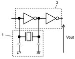
- the oscillation circuit 5 includes a vibrator 1, an amplifier 2, an energizing pulse generating unit 3 for generating an energizing pulse, and a switching unit 4.
- the switching unit 4 switches connection and non-connection of the energizing pulse generating unit 3, the vibrator 1 and the energizing pulse generating unit 3, and the amplifier 2.
- the oscillation circuit 5 further includes an operation command unit (not shown in FIG. 1), and the operation command unit instructs the vibrator 1, the amplifier 2, the energizing pulse generation unit 3, and the switching unit 4 to start operation. It emits.
- the operation command unit is configured by a microcomputer.
- a quartz oscillator or a ceramic oscillator, or a quartz oscillator or a ceramic oscillator to which a capacitor for stably operating them is added is used.
- the ceramic vibrator is more suitable for the present invention than the quartz vibrator because the sharpness of the resonance of the impedance characteristic is slower than that of the quartz vibrator.
- Both oscillators and oscillators use pulses obtained by oscillating at their resonance frequencies for various applications.
- FIG. 2 is a circuit diagram of a vibrator and an amplifier of the oscillation circuit according to the embodiment of this invention.
- FIG. 2 is a circuit diagram showing the vibrator 1 and the amplifier 2 of the oscillation circuit 5 of FIG.
- the vibrator 1 uses, for example, 4 MHz of ceramic oscillator RBRC-G series manufactured by KYOCERA CORPORATION, and the amplifier uses TC74 HCU series and TC74 HC series manufactured by Toshiba Semiconductor Co., Ltd.
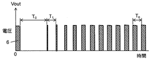
- FIG. 3 is a voltage waveform diagram of the output pulse Vout of the oscillation circuit according to the embodiment of this invention.
- FIG. 3 shows the waveform of the output pulse Vout obtained using the oscillation circuit 5 of FIGS. 1 and 2.
- time 0 base point
- time 0 base point
- an energizing pulse is applied from the energizing pulse generation unit 3 to the vibrator 1 and the amplifier 2.
- the energizing pulse 6 is supplied from the energizing pulse generation unit 3 and in FIG. 3 is a half cycle of a frequency close to the resonance frequency (4 MHz) of the vibrator 1.
- the vibrator 1 When the vibrator 1 is energized by the energizing pulse generation unit 3, the vibration starts and the amplitude of the vibration gradually increases, and after time T0, a pulse of self-oscillation by the vibrator 1 and the amplifier 2 is output .
- the period As can be seen from FIG. 3, the period is close to a constant (4 MHz) at the initial stage of self-sustained pulsation, but the duty (ratio of high time to low time of pulse) is low and gradually approaches 50%.
- the measuring machine timing interval analyzer
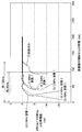
- FIG. 4 is a characteristic diagram in which the abscissa represents time, and the ordinate represents the time difference (difference) with respect to the period (250 ns for the 4 MHz oscillator) in which the pulse finally stabilizes, and the period change of the output pulse Vout of the amplifier 2 is plotted. It is.
- the plurality of characteristic curves use the frequency and wave number of the energizing pulse as parameters.
- “(1) 4 MHz wave number 1” in FIG. 4 is the case where the wave number gives 1 (half period) at the energizing pulse frequency that matches the resonance frequency of the vibrator 1, and the period of the Vout pulse is stable in about 90 ⁇ sec. doing.
- “(2) 4 MHz wave number 3” is the case where the wave number is 3 (2.5 cycles) at the energizing pulse frequency that matches the resonance frequency of the vibrator 1, and the output of the Vout pulse is It is about 90 ⁇ sec until the stabilization of the cycle of the Vout pulse, although it is faster than the above.
- “(3) 3.5 MHz wave number 1” is the case where the wave number gives 1 (half period) at the energizing pulse frequency shifted from the resonance frequency of the vibrator 1 and it takes about 90 ⁇ sec until the period of the Vout pulse becomes stable. It has become.
- “(4) 3.5 MHz wave number 3” is the case where wave number 3 (2.5 cycles) is given at the energizing pulse frequency shifted from the resonance frequency of the vibrator 1, and the output of the Vout pulse is Although it is faster than (3), the stabilization of the cycle of the Vout pulse is about 90 ⁇ sec.
- “(5) 4.5 MHz wave number 1” is the case where the wave number gives 1 (half period) at the energizing pulse frequency shifted from the resonance frequency of the vibrator 1 and it takes about 90 ⁇ sec until the period of the Vout pulse becomes stable. It has become.
- (6) 4.5 MHz wave number 3 is the case where wave number 3 (2.5 periods) is given at the energizing pulse frequency shifted from the resonance frequency of the vibrator 1, and the output of the Vout pulse is Although it is faster than (5), the stabilization of the cycle of the Vout pulse is about 90 ⁇ sec.
- the stabilization of the cycle of the Vout pulse is shortened by 30 ⁇ sec as compared with the case where the activation is not performed. Furthermore, for oscillator 1 (ceramic oscillator) having a resonance frequency of 4 MHz, even if the frequency of the energizing pulse is changed between 3.5 MHz and 4.5 MHz, the period of the Vout pulse changes to 90 ⁇ sec until the stabilization of the period. Absent. When the wave number of the energizing pulse is changed, the output of the Vout pulse appears earlier than that of the wave number of 3 compared to 1. However, it can be seen that the output of the Vout pulse does not change until 90 ⁇ sec until the stabilization of the period of the Vout pulse.
- a 4 MHz oscillator may be a ring oscillator using element delay, or a CR oscillation circuit using a capacitor C and a resistor R.
- the large tolerance of ⁇ 12.5% in either the ring oscillator or the CR oscillator circuit requires little consideration of semiconductor, capacitor, and resistor temperature characteristics and device variations.
- the temperature correction circuit and the frequency adjustment circuit are not required, and the activation pulse generation unit 3 can be realized with a simple configuration.
- external components other than the semiconductor IC can be reduced because they can be used in the semiconductor IC and can be used with little consideration to the large resistance of the temperature characteristic and the variation of the capacitor.
- the activation pulse generation unit 3 sets the pulse frequency of the activation pulse or the pulse width of the activation pulse using a capacitor and a resistor, and a pulse of a frequency within a certain allowable frequency range from the resonance frequency. (Activation pulse) is generated.
- the energizing pulse generator 3 can be designed with a simple circuit configuration.
- the energizing pulse generation unit 3 may set the pulse frequency of the energizing pulse or the pulse width of the energizing pulse using a ring oscillator. As a result, when forming the oscillation circuit 5 on a semiconductor element, it becomes easy.
- the switching unit 4 is in the initial stage of driving the vibrator (one cycle, a half cycle or a period up to a plurality of cycles of the pulse emitted by the energizing pulse generation unit 3 based on the time when the operation command unit issues the operation command).
- the hot start can be realized with an extremely simple circuit configuration without the need for the temperature correction function.
- the ring oscillator configured in the semiconductor IC also has a frequency change due to temperature, since the tolerance is large, it is possible to make a simple circuit without requiring external parts other than the semiconductor IC.
- the simple method of shortening the period from the drive start to the stable oscillation of the oscillation circuit having the oscillator having the above resonance frequency uses the oscillator in the intermittent operation to reduce the power consumption, and the oscillation of the oscillator Is effective as a vibration start means to accelerate the Therefore, the present invention can be applied to an ultrasonic flowmeter which performs pulses in one cycle used to measure the propagation time of ultrasonic waves in intermittent operation.
- the start of stable oscillation of the oscillator can be accelerated, so that the present invention can be applied to applications requiring intermittent operation of the oscillator to reduce power consumption.
- the present invention can be applied even if a vibrator for measuring the propagation time of ultrasonic waves is used by intermittent operation.
Landscapes
- Physics & Mathematics (AREA)
- Chemical & Material Sciences (AREA)
- Crystallography & Structural Chemistry (AREA)
- Electromagnetism (AREA)
- Fluid Mechanics (AREA)
- General Physics & Mathematics (AREA)
- Oscillators With Electromechanical Resonators (AREA)
- Inductance-Capacitance Distribution Constants And Capacitance-Resistance Oscillators (AREA)
Abstract
共振周波数を有する振動子と、振動子に接続されるアンプと、共振周波数から一定の範囲内にある周波数であるパルスを発生させる付勢パルス発生部と、付勢パルス発生部と振動子およびアンプとの接続および非接続を切替える切替え部と、付勢パルス発生部に対して動作開始の指令信号を発する動作指令部とを備え、切替え部は、動作指令部が動作指令を発した時を基点として付勢パルス発生部が発するパルスの1周期、半周期または複数周期までの期間、振動子と付勢パルス発生部とを接続するようにした発振回路。
Description
本発明は、振動子を用いた発振回路の駆動から安定発振までの時間を短縮する発振回路に関する。
電池を用いた機器は、一般に省電力が要求される。例えば、電池を用いた超音波式流量計は省電力化のために、流量計測精度が許容される範囲において断続的な動作をおこなう。超音波式流量計は、超音波の伝播時間測定により流速を求め、これに配管断面積を掛け算することにより流量を算出する。超音波の伝播時間測定には、一定周期のパルスを用いて、超音波の送信から受信までの間にあるパルスの数をカウントして、そのパルスの数にパルスの周期を掛け算して求められる。断続的な流量計測を行う際は、当然ながら流量計測の停止時には、このパルスも停止できれば省電力になる。超音波の伝播時間測定に用いる一定周期のパルスはセラミック振動子または、水晶振動子の振動子を含む発振回路が用いられる。
しかしながら、これらの振動子は動作の開始から安定したパルスの発生までに時間を要するので、流量計測を開始する前から、あらかじめ発振回路をスタートさせておくことが必要となる。このような発振回路のスタートを便宜上、コールドスタートと呼ぶことにする。そしてコールドスタートの期間が長いほど省電力の妨げとなる。
そこで、発振回路の安定動作を早めるための方法として、発振回路部と、リングオシレータとを用い、リングオシレータにより振動子の発振周波数にあうように調整されたパルスを発生させ、基本となる発振回路部にスタート初期からある一定の間、このパルスを与え基本となる発振回路部の安定動作を早めているものがあった(例えば特許文献1参照)。ここで発振回路部は、水晶振動子の振動子と、発振の信頼性を得るためのコンデンサ、抵抗とアンプとからなり発振の基本となる。リングオシレータは、温度補正機能のある電流源を有している。
これには基本となる発振回路部と、リングオシレータとの間には切替え回路が介在する。
このように発振回路部のスタート初期に、外部から発振回路部にパルスを与えて発振回路部のスタートを早める方法を便宜上、ホットスタートと呼ぶことにする。
この方法は、発振回路部のスタートを早める有効な手段であるが、温度補正機能のある電流源を有するリングオシレータを有するなど回路構成が複雑になるという課題がある。
また消費電力低減のために、超音波の伝播時間を計測するパルスを作る振動子を間欠動作により使用し、その振動子の振動を早める振動開始手段を備えた超音波流量計もあった(例えば特許文献2参照)。特許文献2には、特許文献1の方法が超音波の伝播時間計測に用いるパルスの間欠動作に有効であることが記載されている。
しかしながら、上記の構成においては、発振回路部のスタート初期に、外部から発振回路部にパルスを与えて発振回路部のスタートを早めるために、温度補正機能のある電流源を有するリングオシレータなどを有するので、回路構成が複雑になるという課題がある。
本発明の発振回路は、共振周波数を有する振動子と、振動子に接続されるアンプと、共振周波数から一定の範囲内にある周波数であるパルスを発生させる付勢パルス発生部と、付勢パルス発生部と振動子およびアンプとの接続および非接続を切替える切替え部と、付勢パルス発生部に対して動作開始の指令信号を発する動作指令部とを備え、切替え部は、動作指令部が動作指令を発した時を基点として付勢パルス発生部が発するパルスの1周期、半周期または複数周期までの期間、振動子と付勢パルス発生部とを接続するようにした構成である。
このような構成の発振回路は、付勢パルス発生部が振動子の共振周波数に近い付勢パルスを発生させるが、付勢パルスの許容周波数範囲が大きくなるため、温度補正機能の必要もなく極めて簡素な回路構成によりホットスタートを実現できる。
以下、本発明の実施の形態について図面を参照しながら説明する。
(実施の形態)
図1は、本発明の実施の形態の発振回路のブロック図である。図1において発振回路5は、振動子1、アンプ2、付勢パルスを発生させる付勢パルス発生部3、および切替え部4を備えている。ここで切替え部4は、付勢パルス発生部3と、振動子1および付勢パルス発生部3と、アンプ2との接続および非接続を切替える。また、発振回路5は図1に図示していない動作指令部を備え、動作指令部は振動子1、アンプ2、付勢パルス発生部3、および切替え部4に対して動作開始の指令信号を発する。動作指令部は、マイコンで構成される。
図1は、本発明の実施の形態の発振回路のブロック図である。図1において発振回路5は、振動子1、アンプ2、付勢パルスを発生させる付勢パルス発生部3、および切替え部4を備えている。ここで切替え部4は、付勢パルス発生部3と、振動子1および付勢パルス発生部3と、アンプ2との接続および非接続を切替える。また、発振回路5は図1に図示していない動作指令部を備え、動作指令部は振動子1、アンプ2、付勢パルス発生部3、および切替え部4に対して動作開始の指令信号を発する。動作指令部は、マイコンで構成される。
振動子1には水晶振動子またはセラミック振動子、またはそれらを安定に動作させるためのコンデンサが付加された水晶発振器またはセラミック発振器が用いられる。セラミック振動子は、水晶振動子に比べインピーダンス特性の共振の先鋭度が緩やかなので、本発明には水晶振動子よりも適している。何れの振動子、発振器もその共振周波数により発振させて得られるパルスを様々な用途に用いる。
図2は、本発明の実施の形態の発振回路の振動子とアンプとの回路図である。図2は図1の発振回路5の振動子1、アンプ2の部分を示した回路図である。振動子1は例えば京セラ株式会社製のセラミック発振子RBRC-Gシリーズの4MHz用を用い、アンプは株式会社東芝セミコンダクター製TC74HCUシリーズとTC74HCシリーズとを用いている。
図3は、本発明の実施の形態の発振回路の出力パルスVoutの電圧波形図である。図3は、図1および図2の発振回路5を用いて得られる出力パルスVoutの波形を示している。図3において、時間0(基点)は電源があらかじめ供給されスタンバイ状態にあるアンプ2に、動作指令部(図示せず)から動作開始の指令信号が発せられる時である。また、時間0(基点)のタイミングで、付勢パルス発生部3から振動子1、アンプ2に付勢パルスが与えられる。付勢パルス6は付勢パルス発生部3から供給され、図3においては振動子1の共振周波数(4MHz)に近い周波数の半周期分としている。
付勢パルス発生部3により振動子1が付勢されると振動がはじまり、徐々に振動の振幅が大きくなり、時間T0後に振動子1とアンプ2とによる自励発振のパルスが出力されている。図3からわかるように、自励発振の初期において周期は一定(4MHz)に近いが、デューティー(パルスのHighの時間とLowの時間との比)は低く、徐々に50%に近づいている。一定に見える周期も測定機(タイミングインターバルアナライザー)により測定すると、本発明の実施の形態の発振回路の出力パルスVoutの周期変化をプロットした特性図である図4のように変化していることがわかる。
図4は、電源があらかじめ供給されスタンバイ状態にあるアンプ2に動作指令部(図示せず)から動作開始の指令信号が発せられるタイミングを基点(0)とし、そのタイミングで付勢パルス発生部3から振動子1、アンプ2に付勢パルスが与えられる。図4は横軸に時間、縦軸に最終的にパルスが安定する周期(4MHz振動子なので周期は250ns)に対する時間差(差分)をとり、アンプ2の出力パルスVoutの周期変化をプロットした特性図である。複数ある特性カーブは、与える付勢パルスの周波数と波数とをパラメータとしたものである。
図4の「(1)4MHz 波数1」は、振動子1の共振周波数に合った付勢パルス周波数において波数が1(半周期)を与えた場合であり、約90μsecにおいてVoutパルスの周期が安定している。
「(2)4MHz 波数3」は、振動子1の共振周波数に合った付勢パルス周波数において波数が3(2.5周期)を与えた場合であり、Voutパルスの出力が現れるのが(1)に比べて早くなっているが、Voutパルスの周期の安定までは約90μsecとなっている。
「(3)3.5MHz 波数1」は、振動子1の共振周波数からずれた付勢パルス周波数において波数が1(半周期)を与えた場合であり、Voutパルスの周期の安定までは約90μsecとなっている。
「(4)3.5MHz 波数3」は、振動子1の共振周波数からずれた付勢パルス周波数において波数が3(2.5周期)を与えた場合であり、Voutパルスの出力が現れるのが(3)に比べて早くなっているが、Voutパルスの周期の安定までは約90μsecとなっている。
「(5)4.5MHz 波数1」は、振動子1の共振周波数からずれた付勢パルス周波数において波数が1(半周期)を与えた場合であり、Voutパルスの周期の安定までは約90μsecとなっている。
「(6)4.5MHz 波数3」は、振動子1の共振周波数からずれた付勢パルス周波数において波数が3(2.5周期)を与えた場合であり、Voutパルスの出力が現れるのが(5)に比べて早くなっているが、Voutパルスの周期の安定までは約90μsecとなっている。
「(7)自励のみ」は、付勢を行なわない場合であり、Voutパルスの出力が現れるのがもっとも遅く、周期の安定までは約120μsecとなっている。
これらのことからわかるように付勢パルスにより付勢した場合は、付勢しない場合に比べVoutパルスの周期の安定まで30μsec短縮されている。さらに、4MHzの共振周波数を持つ振動子1(セラミック発振器)に対して、3.5MHzから4.5MHzの間において付勢パルスの周波数を変えても、Voutパルスの周期の安定までは90μsecと変わらない。また付勢パルスの波数を変えた場合、波数が3の方が1に比べてVoutパルスの出力が現れるのが早いが、いずれもVoutパルスの周期の安定までは90μsecと変わらないことがわかる。
4MHzの振動子1の共振周波数に対し、3.5MHzと4.5MHzは±12.5%になり、これが付勢パルスの許容周波数範囲にあたる。許容周波数範囲内にある付勢パルスをつくる付勢パルス発生部3の回路構成を考える場合、非常に簡単な構成とすることができる条件となる。例えば半導体ICにより回路を構成する場合、4MHzの発振器は素子の遅延を利用したリングオシレータ、またはコンデンサCと抵抗器RとによるCR発振回路が考えられる。リングオシレータ、またはCR発振回路どちらの場合でも±12.5%の大きな許容値は、半導体、コンデンサ、および抵抗器の温度特性、および素子バラツキをほとんど考慮する必要がない。このため温度補正回路、および周波数調整回路が不要となり、付勢パルス発生部3が簡単な構成により実現できる。特にCR発振回路では、半導体IC内において構成するや温度特性の大きな抵抗、およびコンデンサのバラツキをほとんど考慮することなく使用できるので、半導体IC以外の外付け部品を削減できる。
このように付勢パルス発生部3は、コンデンサと抵抗とを用いて付勢パルスのパルス周波数、または付勢パルスのパルス幅を設定し、共振周波数から一定の許容周波数範囲内にある周波数のパルス(付勢パルス)を発生させる。その結果、簡素な回路構成により付勢パルス発生部3を設計することができる。
また付勢パルス発生部3は、リングオシレータを用いて付勢パルスのパルス周波数、または付勢パルスのパルス幅を設定してもよい。その結果、半導体素子上に発振回路5を構成する際、容易となる。
また、切替え部4は、振動子の駆動初期(前記動作指令部が動作指令を発した時を基点として付勢パルス発生部3が発するパルスの1周期、半周期または複数周期までの期間)において振動子と付勢パルス発生部とを接続するようにすることで、温度補正機能の必要もなく極めて簡素な回路構成によりホットスタートを実現できる。
また、半導体IC内において構成されるリングオシレータも温度による周波数変化があるが、許容値が大きいことから、半導体IC以外の外付け部品を必要とせず、簡素な回路とすることができる。
以上の共振周波数を有する振動子を有する発振回路の駆動開始から安定発振までの期間を短縮する簡素な方法は、消費電力低減のために、振動子を間欠動作において使用し、その振動子の振動を早める振動開始手段として有効である。そのため、超音波の伝播時間を計測するために用いる1周期毎のパルスを間欠動作において行なう超音波流量計にも適用することができる。
以上のように、本発明の発振回路によれば、振動子の安定発振の開始を速められるので、消費電力低減のために振動子の間欠動作が必要な用途に適用が可能である。例えば電池駆動の超音波流量計において、超音波の伝播時間計測を行うための振動子を間欠動作により用いても本発明を適用すれば正確な流量計測が可能になる。
1 振動子
2 アンプ
3 付勢パルス発生部
4 切替え部
5 発振回路
6 付勢パルス
2 アンプ
3 付勢パルス発生部
4 切替え部
5 発振回路
6 付勢パルス
Claims (5)
- 共振周波数を有する振動子と、
前記振動子に接続されるアンプと、
前記共振周波数から一定の範囲内にある周波数であるパルスを発生させる付勢パルス発生部と、
前記付勢パルス発生部と前記振動子および前記アンプとの接続および非接続を切替える切替え部と、
前記付勢パルス発生部に対して動作開始の指令信号を発する動作指令部とを備え、
前記切替え部は、前記動作指令部が動作指令を発した時を基点として前記付勢パルス発生部が発するパルスの1周期、半周期または複数周期までの期間、前記振動子と前記付勢パルス発生部とを接続するようにしたことを特徴とする発振回路。 - 請求項1記載の発振回路であって、
前記振動子はセラミック振動子を用いたことを特徴とする発振回路。 - 請求項1記載の発振回路であって、
前記付勢パルス発生部はコンデンサと抵抗とを用いて前記付勢パルスのパルス周波数または前記付勢パルスのパルス幅を設定したことを特徴とする発振回路。 - 請求項1記載の発振回路であって、
前記付勢パルス発生部はリングオシレータを用いて前記付勢パルスのパルス周波数または前記付勢パルスのパルス幅を設定したことを特徴とする発振回路。 - 請求項1の発振回路を用い、前記発振回路から得られるパルスを超音波の伝播時間計測に用いたことを特徴とする超音波流量計。
Priority Applications (3)
| Application Number | Priority Date | Filing Date | Title |
|---|---|---|---|
| EP09833200.0A EP2369737A4 (en) | 2008-12-18 | 2009-12-16 | Oscillation circuit |
| CN200980151245.1A CN102257725B (zh) | 2008-12-18 | 2009-12-16 | 振荡电路 |
| US13/132,556 US8413523B2 (en) | 2008-12-18 | 2009-12-16 | Oscillation circuit |
Applications Claiming Priority (2)
| Application Number | Priority Date | Filing Date | Title |
|---|---|---|---|
| JP2008322155A JP2010147758A (ja) | 2008-12-18 | 2008-12-18 | 発振回路 |
| JP2008-322155 | 2008-12-18 |
Publications (1)
| Publication Number | Publication Date |
|---|---|
| WO2010070892A1 true WO2010070892A1 (ja) | 2010-06-24 |
Family
ID=42268572
Family Applications (1)
| Application Number | Title | Priority Date | Filing Date |
|---|---|---|---|
| PCT/JP2009/006908 Ceased WO2010070892A1 (ja) | 2008-12-18 | 2009-12-16 | 発振回路 |
Country Status (5)
| Country | Link |
|---|---|
| US (1) | US8413523B2 (ja) |
| EP (1) | EP2369737A4 (ja) |
| JP (1) | JP2010147758A (ja) |
| CN (1) | CN102257725B (ja) |
| WO (1) | WO2010070892A1 (ja) |
Families Citing this family (7)
| Publication number | Priority date | Publication date | Assignee | Title |
|---|---|---|---|---|
| US9161425B2 (en) * | 2011-08-17 | 2015-10-13 | Surefire, Llc | Lighting device control using variable inductor |
| EP2884658A1 (en) | 2013-12-16 | 2015-06-17 | Telefonaktiebolaget L M Ericsson (publ) | Oscillator circuit |
| US9246435B1 (en) | 2015-02-09 | 2016-01-26 | Qualcomm Incorporated | Method to pre-charge crystal oscillators for fast start-up |
| JP6488878B2 (ja) | 2015-05-18 | 2019-03-27 | 富士通株式会社 | 温度補償回路およびレーダ装置 |
| US10135390B2 (en) * | 2015-06-22 | 2018-11-20 | Microchip Technology Incorporated | Periodic kick-starter for a crystal oscillator |
| JP7149810B2 (ja) * | 2018-11-06 | 2022-10-07 | 株式会社日立ハイテク | 自動分析装置 |
| KR20230132223A (ko) | 2022-03-08 | 2023-09-15 | 도레이첨단소재 주식회사 | 불소기 함유 이형필름 및 이의 제조방법 |
Citations (5)
| Publication number | Priority date | Publication date | Assignee | Title |
|---|---|---|---|---|
| JPH11284438A (ja) * | 1998-03-27 | 1999-10-15 | Kinseki Ltd | 圧電発振器 |
| JP2003032039A (ja) * | 2001-07-16 | 2003-01-31 | Toyo Commun Equip Co Ltd | 圧電発振回路 |
| US6819195B1 (en) | 2003-03-07 | 2004-11-16 | Ami Semiconductor, Inc. | Stimulated quick start oscillator |
| US20080081610A1 (en) | 2006-09-29 | 2008-04-03 | Polycom Inc. | Desktop phone with interchangeable wireless handset |
| WO2008081610A1 (ja) * | 2006-12-27 | 2008-07-10 | Panasonic Corporation | 超音波流量計 |
Family Cites Families (12)
| Publication number | Priority date | Publication date | Assignee | Title |
|---|---|---|---|---|
| US4584676A (en) * | 1982-03-15 | 1986-04-22 | Measurement Systems, Inc. | Method of and apparatus for pipe length measurement |
| CH672187A5 (ja) * | 1986-10-23 | 1989-10-31 | Landis & Gyr Gmbh | |
| JPS63113309U (ja) * | 1987-01-16 | 1988-07-21 | ||
| JPS63187412U (ja) * | 1987-05-22 | 1988-11-30 | ||
| JPS644102A (en) * | 1987-06-25 | 1989-01-09 | Nec Corp | Crystal oscillation circuit |
| JPH0575343A (ja) * | 1991-09-17 | 1993-03-26 | Mitsubishi Electric Corp | クロツク信号出力回路 |
| JPH0895539A (ja) * | 1994-09-28 | 1996-04-12 | Nec Corp | プレゼンテーション支援装置 |
| CN1178009A (zh) * | 1996-01-25 | 1998-04-01 | 株式会社爱德万测试 | 延迟时间测定方法及延迟时间测定用脉冲发生装置 |
| JPH09270639A (ja) * | 1996-03-29 | 1997-10-14 | Kinseki Ltd | 発振回路 |
| JP3446602B2 (ja) * | 1998-04-16 | 2003-09-16 | セイコーエプソン株式会社 | 圧電発振器、発振器調整システムおよび発振器調整方法 |
| US6229402B1 (en) * | 1998-05-28 | 2001-05-08 | Canon Kabushiki Kaisha | Driving circuit for vibration type actuator apparatus |
| JP2002016437A (ja) * | 2000-06-28 | 2002-01-18 | Nec Microsystems Ltd | 圧電発振器 |
-
2008
- 2008-12-18 JP JP2008322155A patent/JP2010147758A/ja active Pending
-
2009
- 2009-12-16 CN CN200980151245.1A patent/CN102257725B/zh not_active Expired - Fee Related
- 2009-12-16 EP EP09833200.0A patent/EP2369737A4/en not_active Withdrawn
- 2009-12-16 WO PCT/JP2009/006908 patent/WO2010070892A1/ja not_active Ceased
- 2009-12-16 US US13/132,556 patent/US8413523B2/en not_active Expired - Fee Related
Patent Citations (5)
| Publication number | Priority date | Publication date | Assignee | Title |
|---|---|---|---|---|
| JPH11284438A (ja) * | 1998-03-27 | 1999-10-15 | Kinseki Ltd | 圧電発振器 |
| JP2003032039A (ja) * | 2001-07-16 | 2003-01-31 | Toyo Commun Equip Co Ltd | 圧電発振回路 |
| US6819195B1 (en) | 2003-03-07 | 2004-11-16 | Ami Semiconductor, Inc. | Stimulated quick start oscillator |
| US20080081610A1 (en) | 2006-09-29 | 2008-04-03 | Polycom Inc. | Desktop phone with interchangeable wireless handset |
| WO2008081610A1 (ja) * | 2006-12-27 | 2008-07-10 | Panasonic Corporation | 超音波流量計 |
Non-Patent Citations (1)
| Title |
|---|
| See also references of EP2369737A4 |
Also Published As
| Publication number | Publication date |
|---|---|
| CN102257725A (zh) | 2011-11-23 |
| EP2369737A4 (en) | 2017-05-10 |
| US8413523B2 (en) | 2013-04-09 |
| EP2369737A1 (en) | 2011-09-28 |
| JP2010147758A (ja) | 2010-07-01 |
| CN102257725B (zh) | 2014-05-21 |
| US20110226067A1 (en) | 2011-09-22 |
Similar Documents
| Publication | Publication Date | Title |
|---|---|---|
| WO2010070892A1 (ja) | 発振回路 | |
| US7482888B1 (en) | Fast startup resonant element oscillator | |
| KR101113772B1 (ko) | 초음파 유량계 | |
| TWI313962B (en) | Method and apparatus for a crystal oscillator to achieve fast start-up time, low power and frequency calibration | |
| JP2002248153A (ja) | 超音波美容器 | |
| JP2010087571A (ja) | 発振回路およびその制御方法 | |
| JP2004506370A (ja) | デジタルクロック逓倍回路のための方法および装置 | |
| JP2000334019A (ja) | 超音波美容器 | |
| JP3689982B2 (ja) | 超音波流速計 | |
| JP4649822B2 (ja) | 流体の流れ計測装置 | |
| CN118232909A (zh) | 晶振控制电路及方法 | |
| JP2004336875A (ja) | 超音波モータの駆動装置及び駆動方法 | |
| JPH11341841A (ja) | 振動型アクチュエータの駆動回路 | |
| JPH05212331A (ja) | 超音波デバイス駆動回路 | |
| CN112688669A (zh) | 一种5v驱动的高压脉冲激励电路 | |
| GB2488390A (en) | Object detection | |
| JP4788269B2 (ja) | 圧電発振器 | |
| JP2000304850A (ja) | 超音波センサの送波回路 | |
| JPH01204509A (ja) | 超音波発振器 | |
| JPH1165678A (ja) | 振動機の制御装置及び振動機の制御方法 | |
| UA153337U (uk) | Електромагнітний резонансний вібраційний привід | |
| JPH1052073A (ja) | 超音波モータの駆動回路 | |
| RU2311730C1 (ru) | Генератор импульсов | |
| JP5533051B2 (ja) | 信号発生部付き発振回路 | |
| JPS599077B2 (ja) | 超音波発振器 |
Legal Events
| Date | Code | Title | Description |
|---|---|---|---|
| WWE | Wipo information: entry into national phase |
Ref document number: 200980151245.1 Country of ref document: CN |
|
| 121 | Ep: the epo has been informed by wipo that ep was designated in this application |
Ref document number: 09833200 Country of ref document: EP Kind code of ref document: A1 |
|
| WWE | Wipo information: entry into national phase |
Ref document number: 2009833200 Country of ref document: EP |
|
| WWE | Wipo information: entry into national phase |
Ref document number: 13132556 Country of ref document: US |
|
| NENP | Non-entry into the national phase |
Ref country code: DE |