WO2010071088A1 - アバランシ・フォトダイオード - Google Patents
アバランシ・フォトダイオード Download PDFInfo
- Publication number
- WO2010071088A1 WO2010071088A1 PCT/JP2009/070783 JP2009070783W WO2010071088A1 WO 2010071088 A1 WO2010071088 A1 WO 2010071088A1 JP 2009070783 W JP2009070783 W JP 2009070783W WO 2010071088 A1 WO2010071088 A1 WO 2010071088A1
- Authority
- WO
- WIPO (PCT)
- Prior art keywords
- layer
- electrode
- light absorption
- avalanche multiplication
- avalanche
- Prior art date
- Legal status (The legal status is an assumption and is not a legal conclusion. Google has not performed a legal analysis and makes no representation as to the accuracy of the status listed.)
- Ceased
Links
Images


Classifications
-
- H—ELECTRICITY
- H10—SEMICONDUCTOR DEVICES; ELECTRIC SOLID-STATE DEVICES NOT OTHERWISE PROVIDED FOR
- H10F—INORGANIC SEMICONDUCTOR DEVICES SENSITIVE TO INFRARED RADIATION, LIGHT, ELECTROMAGNETIC RADIATION OF SHORTER WAVELENGTH OR CORPUSCULAR RADIATION
- H10F30/00—Individual radiation-sensitive semiconductor devices in which radiation controls the flow of current through the devices, e.g. photodetectors
- H10F30/20—Individual radiation-sensitive semiconductor devices in which radiation controls the flow of current through the devices, e.g. photodetectors the devices having potential barriers, e.g. phototransistors
- H10F30/21—Individual radiation-sensitive semiconductor devices in which radiation controls the flow of current through the devices, e.g. photodetectors the devices having potential barriers, e.g. phototransistors the devices being sensitive to infrared, visible or ultraviolet radiation
- H10F30/22—Individual radiation-sensitive semiconductor devices in which radiation controls the flow of current through the devices, e.g. photodetectors the devices having potential barriers, e.g. phototransistors the devices being sensitive to infrared, visible or ultraviolet radiation the devices having only one potential barrier, e.g. photodiodes
- H10F30/225—Individual radiation-sensitive semiconductor devices in which radiation controls the flow of current through the devices, e.g. photodetectors the devices having potential barriers, e.g. phototransistors the devices being sensitive to infrared, visible or ultraviolet radiation the devices having only one potential barrier, e.g. photodiodes the potential barrier working in avalanche mode, e.g. avalanche photodiodes
- H10F30/2255—Individual radiation-sensitive semiconductor devices in which radiation controls the flow of current through the devices, e.g. photodetectors the devices having potential barriers, e.g. phototransistors the devices being sensitive to infrared, visible or ultraviolet radiation the devices having only one potential barrier, e.g. photodiodes the potential barrier working in avalanche mode, e.g. avalanche photodiodes in which the active layers form heterostructures, e.g. SAM structures
Definitions
- the present invention relates to an element structure of an electron injection avalanche photodiode (avalanche multiplication diode, hereinafter abbreviated as APD) suitable for ultrahigh-speed operation.
- APD electron injection avalanche photodiode
- APD has been widely introduced as a high sensitivity optical receiving device such as a 10 Gb / s system using a long wavelength band (1.5 micron band).
- a typical APD operating in the long wavelength band is a hole injection type using InP as an avalanche multiplication layer.
- hole injection type APDs have a fabrication process that defines an avalanche multiplication region by Zn thermal diffusion into InP.
- precise control of Zn thermal diffusion is difficult, and the device manufacturing yield is generally poor, which is a major technical problem.
- An electron injection type APD that is advantageous in principle in terms of speeding up and excess noise characteristics is also known.
- An electron injection type APD generally has a structure in which InAlAs is an avalanche multiplication layer.
- the electron injection type APD has a gain bandwidth product (GB product) larger than that of the hole injection type, and has excellent reception sensitivity.
- GB product gain bandwidth product
- guard ring technology for suppressing the edge breakdown around the junction has not reached the perfection level of the hole injection type APD.
- This is an “ion implantation type guard ring structure” normally used in hole injection type APDs, that is, the depth distribution of acceptor ions such as Be is adjusted to reduce the multiplication factor (increase the breakdown voltage). This is because it is difficult to form the structure into an electron injection type APD.
- FIG. 6 shows an example of a conventional electron injection type APD having a buried n-electrode structure, which is a cross-section of a so-called buried n-electrode structure in which a convex portion is provided on a part of the n-electrode disposed on the substrate side (Patent Document). See 1 and 2, 4).
- 6 includes an n electrode layer 31, an n electrode connection layer 32, an avalanche multiplication layer 34, an electric field control layer 35, a band gap gradient layer 36, a low-concentration light absorption layer 37a, a p-type light absorption layer 37b, and a p electrode.
- the layer 38 and the p-electrode 39 are sequentially stacked, and the light absorption portion composed of the low-concentration light absorption layer 37a and the p-type light absorption layer 37b has a mesa shape. Further, an n electrode 40 is disposed on the n electrode layer 31.
- the n-electrode connection layer 32 includes an n-type region 32a and a low doping concentration region surrounding the n-type region 32a.
- the n-type region 32a is a buried n-type region.
- a portion indicated by a broken line is an electric field concentration portion 21 where an electric field is concentrated locally.
- the light absorption part combining the low-concentration light absorption layer 37a and the p-type light absorption layer 37b can maximize the band at the same light receiving sensitivity by optimizing the ratio of the thicknesses of both layers (Patent Literature). 3). That is, it is possible to design an element that maximizes the light absorption rate and maximizes the light receiving sensitivity in the same band.
- This structure is effective for an electron injection type APD, but almost no effect can be expected with a hole injection type APD.
- the APD of FIG. 6 has the advantage that the avalanche region can be confined inside, and the aging of the side surface and the surface of the mesa can be suppressed at the same time.
- an electric field concentration (edge electric field) is likely to occur at the corner of the outer peripheral portion of the n-type region 32a due to the convex shape of the n-type region 32a in the operating state. . Since the electric field lines of the edge electric field spread two-dimensionally, the electric field tends to decrease because the upper side of the avalanche multiplication layer 34 is away from the n-type region 32a.
- the edge electric field is concentrated near the corner of the outer peripheral portion of the n-type region 32a (electric field concentration portion 21), and when the electric field of the electric field concentration portion 21 reaches the avalanche multiplication layer 34, the electric field of the ionization rate is obtained. Since the dependence is steep, the avalanche multiplication layer 34 is liable to cause a phenomenon in which breakdown occurs at a voltage lower than the active region at the center of the element, so-called edge breakdown. When edge breakdown occurs, the avalanche multiplication factor of the active region cannot be made sufficiently large, and the difference between the breakdown voltage and the operating voltage becomes small, so that avalanche excess noise increases. Further, the thicker the low-concentration light absorption layer 37a, the greater the influence of edge breakdown by the electric field concentration portion 21.
- the present invention provides an electron injection APD that can suppress the edge breakdown without controlling the doping profile of the n-type region with high accuracy, while solving the above-mentioned problems based on a buried n-electrode structure. For the purpose.
- a buffer layer having a low ionization rate is inserted between the n-electrode connection layer and the avalanche multiplication layer.
- the APD according to the present invention includes an n electrode layer, an n electrode connection layer, an avalanche multiplication layer, an electric field control layer, a band gap gradient layer, a low concentration light absorption layer, a p-type light absorption layer, and a p electrode layer.
- the n-electrode connection layer is a semiconductor structure having an n-type region arranged inside the outer periphery of the avalanche multiplication layer when viewed from the stacking direction.
- a buffer layer having an ionization rate lower than that of the avalanche multiplication layer is inserted between the n-electrode connection layer and the avalanche multiplication layer, and the p-type light absorption layer includes the p-type light absorption layer.
- a reverse bias is applied between the electrode layer and the n electrode layer, a region that maintains a neutral normal state is formed on the p electrode layer side.
- a region that maintains a neutral normal state is formed on substantially the entire surface on the p electrode layer side, but a region that maintains a neutral normal state does not occur in a specific part even on the p electrode layer side.
- the buffer layer By inserting the buffer layer, even if an edge electric field is generated, the electric field concentration portion is separated from the avalanche multiplication layer, so that edge breakdown can be avoided.
- the present invention can provide an electron injection type APD that can suppress edge breakdown without controlling the doping profile of the n-type region with high accuracy, while being based on a buried n-electrode structure.
- the APD according to the present invention can be formed on a substrate.
- the substrate side is an n-electrode layer
- the APD forms the laminated structure on the substrate with the n-electrode layer as the substrate side, and includes a light-absorbing portion comprising the low-concentration light-absorbing layer and the p-type light-absorbing layer Has a mesa shape, and the n-type region of the n-electrode connection layer is disposed on the inner side of the mesa-shaped outer periphery of the light absorbing portion when viewed from the stacking direction.
- the substrate side can be a p-electrode layer.
- the APD according to the present invention includes an n electrode layer, an n electrode connection layer, an avalanche multiplication layer, an electric field control layer, a band gap gradient layer, a low concentration light absorption layer, a p-type light absorption layer, and a p electrode layer.
- a buffer layer having an ionization rate lower than that of the avalanche multiplication layer is inserted between the n-electrode connection layer and the avalanche multiplication layer, and the p-type
- the light absorption layer has a region that maintains a neutral normal state except for a part on the p electrode layer side when a reverse bias is applied between the p electrode layer and the n electrode layer.
- the stacked structure is formed on the substrate with the p-electrode layer as the substrate side, the n-electrode connection layer and the n-electrode layer form a mesa shape, and the mesa shape is viewed from the stacking direction. And disposed inside the outer periphery of the buffer layer.
- the buffer layer of the APD according to the present invention preferably has a doped portion doped with impurities on at least the avalanche multiplication layer side. If a high-concentration and thin donor doping layer is provided on the avalanche multiplication layer side, an electric field change on the step can be made, and ionization is suppressed by adjusting the donor doping amount so as to suppress an electric field increase due to electric field concentration. It becomes possible.
- the buffer layer and the avalanche multiplication layer of the APD according to the present invention are semiconductors having different compositions, and the buffer layer can have a wider band gap than the avalanche multiplication layer. Since the buffer layer has a large band gap, the ionization rate of the buffer layer can be relatively lowered even if the buffer layer and the avalanche multiplication layer have the same electric field strength. It is also possible to combine the above-described methods of providing a high concentration and thin donor doping.
- the present invention can provide an electron-injection APD that can suppress edge breakdown without controlling the doping profile of the n-type region with high accuracy, while using a buried n-electrode structure as a basis.
- FIG. 1 is a schematic cross-sectional view of an element for explaining an APD according to a first embodiment.
- 1 includes an n electrode layer 31, an n electrode connection layer 32, a buffer layer 33, an avalanche multiplication layer 34, an electric field control layer 35, a band gap inclined layer 36, a low-concentration light absorption layer 37a, a p-type light absorption layer.
- 37b and a p-electrode layer 38 are sequentially stacked, and a light absorption part 37 including at least a low-concentration light absorption layer 37a and a p-type light absorption layer 37b is a mesa-shaped electron injection type APD. Further, in the APD of FIG.
- the n electrode layer 31 is n-InP.
- the n-electrode connection layer 32 includes an n-type region 32a and a lightly doped region 32b, and both are n-InAlAs.
- the buffer layer 33 is InAlAs.
- the buffer layer 33 has a low doping concentration in order to reduce the change in electric field.
- the buffer layer 33 has a doped portion 33a doped with impurity Si on the avalanche multiplication layer 34 side in order to narrow the electric field step.
- the avalanche multiplication layer 34 is kept at a low impurity concentration.
- the impurity concentration of the avalanche multiplication layer 34 is too high, the electric field E of the avalanche multiplication layer 34 changes greatly, and when a constant multiplication factor is obtained, it causes a tunnel current due to nonuniformity of the electric field. For this reason, the doping concentration of the avalanche multiplication layer 34 is kept low so that the change in the electric field is small.
- the avalanche multiplication layer 34 is InAlAs with a low doping concentration.
- the electric field control layer 35 is p-InAlAs.
- the band gap gradient layer 36 is InAlGaAs.
- the low concentration light absorption layer 37a is InGaAs.
- the p-type light absorption layer 37b is p-type doped InGaAs.
- the mesa side wall vicinity of the p-type light absorption layer 37b is a portion that does not become a neutral normal state even at the time of reverse bias.
- the low-concentration light absorption layer 37a side of the p-type light absorption layer 37b is also a portion that does not become a neutral normal state.
- the p electrode layer 38 is p-InAlGaAs.
- an n-electrode layer 31 and a low-concentration layer to be an n-electrode connection layer 32 are epitaxially grown on the substrate 30 using the MO-VPE method or the like. Thereafter, Si is ion-implanted into a portion to be the n-type region 32a, and this portion is used as an n-type region having a buried n-electrode structure. After the activation annealing is performed, the buffer layer 33, the doping portion 33a, and then the p electrode layer 38 are epitaxially grown again.
- Element processing is basically the same as a normal APD manufacturing process, and after forming a double mesa using chemical etching, an n-electrode 40 and a p-electrode 39 are deposited, and wiring separation is performed as necessary.
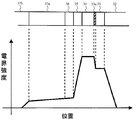
- each layer including the n-type region 32a of the electrode connection layer 32 up to the low-concentration light absorption layer 37a is depleted, and the central portion of the element is in the stacking direction as shown in FIG.
- the electric field strength distribution is
- the step-like electric field change from the buffer layer 33 to the avalanche multiplication layer 34 can be easily formed by adjusting the doping concentration and the layer thickness of the thin doping portion 33 a formed in the buffer layer 33.
- the Si donor concentration is 10 18 cm ⁇ 3 and the thickness is 14 nm
- the step amount of the electric field strength is 200 kV / cm, and the ionization rate of the buffer layer is sufficiently lowered.
- the step amount of the electric field strength is determined by the product of the donor concentration and the thickness, both can be determined as appropriate.
- the electric field concentration portion 21 is generated at the corner of the n-type region 32a.
- the electric field concentration portion 21 is separated from the avalanche multiplication layer 34 by inserting the buffer layer 33, the phenomenon in which breakdown occurs at a voltage lower than that of the active region in the central portion of the element is greatly relieved.
- the buffer layer 33 has a low ionization rate, breakdown does not easily occur even if the electric field concentration portion 21 exists. Therefore, the APD of FIG. 1 can suppress the occurrence of edge breakdown.
- FIG. 3 is a schematic cross-sectional view of an element for explaining the APD of the second embodiment.
- the APD in FIG. 3 is also an electron injection type APD that employs a buried n-electrode structure in the same manner as the APD in FIG.
- the difference between the APD of FIG. 3 and the APD of FIG. 1 is that the buffer layer 33 of the APD of FIG. 3 does not necessarily have the doping portion 33a, and the buffer layer 33 has a composition different from that of the avalanche multiplication layer 34. It is a semiconductor, and the buffer layer 33 has a wider band gap than the avalanche multiplication layer 34.
- the n electrode layer 31 to the buffer layer 33 have the same composition as the APD in FIG.
- the avalanche multiplication layer 34 is InAlGaAs with a low doping concentration.
- the electric field control layer 35 is p-InAlGaAs.
- the band gap inclined layer 36 is an InAlGaAs layer whose composition is adjusted so as to connect the band gap between the electric field control layer 35 and the low concentration light absorption layer 37a, and from the low concentration light absorption layer 37a to the p electrode layer 38, The same composition as APD of 1.
- the APD of FIG. 3 can also be created as described in FIG.
- FIG. 4 is a band diagram of the central portion in the operating state of the APD of FIG.
- an InAlAs buffer layer 33 having a larger band gap than InAlGaAs is inserted between the electrode connection layer 32 and the avalanche multiplication layer 34.
- InAlAs having a larger band gap has a relatively lower ionization rate than InAlGaAs. Therefore, also in the APD of FIG. 3, the buffer layer 33 has a lower ionization rate than the avalanche multiplication layer 34.
- the electric field concentration part 21 where the electric field concentrates is generated at the corner of the n-type region 32a.
- the electric field concentration portion 21 is separated from the avalanche multiplication layer 34 by inserting the buffer layer 33, the phenomenon in which breakdown occurs at a voltage lower than that of the active region in the central portion of the element is greatly relieved.
- the buffer layer 33 has a low ionization rate, breakdown does not easily occur even if the electric field concentration portion 21 exists. Therefore, the APD of FIG. 3 can suppress the occurrence of edge breakdown.
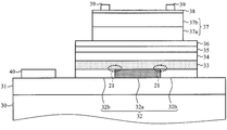
- FIG. 5 is a schematic cross-sectional view of an element for explaining an APD according to a third embodiment.
- 32 and the n-electrode layer 31 are sequentially laminated, and the p-electrode 39 and the n-electrode 40 are formed.
- This structure is roughly equivalent to the semiconductor structure of the second embodiment described above arranged upside down.
- the n-electrode connection layer 32 is not on the substrate side but on the upper side, it is not necessarily formed as a selective n layer by Si ion implantation as in the first and second embodiments. What is necessary is just to decide a shape as a mesa. That is, the n-electrode connection layer 32 can be provided with the same function as the APD having a buried n-electrode structure by being arranged on the inner side of the outer periphery of the mesa below the buffer layer 33.
- the electric field concentration portion 21 where the electric field concentrates is generated at the corner of the n-type region 32.
- the electric field concentration portion 21 is separated from the avalanche multiplication layer 34 by inserting the buffer layer 33, the phenomenon in which breakdown occurs at a voltage lower than that of the active region in the central portion of the element is greatly relieved.
- the buffer layer 33 has a low ionization rate, breakdown does not easily occur even if the electric field concentration portion 21 exists. Therefore, the APD of FIG. 5 can suppress the occurrence of edge breakdown.
- an example of an APD using an avalanche multiplication layer of InAlAs and InAlGaAs and an optical absorption layer of InGaAs has been described.
- the type of semiconductor material is not limited, and an APD formed by a combination of other semiconductor materials. The same effect can be obtained also in.
- Electric field concentration part 30 Substrate 31: n electrode layer 32: n electrode connection layer 32a: n-type region 33: buffer layer 34: avalanche multiplication layer 35: electric field control layer 36: band gap inclined layer 37: light absorption part 37a: low concentration light absorption layer 37b: p-type light absorption layer 38: p electrode layer 39: p electrode 40: n electrode
Landscapes
- Light Receiving Elements (AREA)
Abstract
埋め込みn電極構造のn形領域のドーピングプロファイルを高い精度で制御することなく、エッジブレークダウンを抑制できる構造の埋め込みn電極構造の電子注入形APDを提供することを目的とする。本発明に係るAPDは、n電極接続層32となだれ増倍層34との間にイオン化率の低いバッファ層33を挿入することとした。具体的には、n電極層31、n電極接続層32、バッファ層33、なだれ増倍層34、電界制御層35、バンドギャップ傾斜層36、低濃度光吸収層37a、p形光吸収層37b及びp電極層38が順次積層され、少なくとも低濃度光吸収層37aとp形光吸収層37bからなる光吸収部37がメサ形状をなす電子注入形のAPDである。
Description
本発明は超高速動作に適した電子注入形のアバランシ・フォトダイオード(なだれ増倍形ダイオード、以下、APDと略記する。)の素子構造に関するものである。
APDは、高感度の光受信デバイスとして、長波長帯(1.5ミクロン帯)を使った10Gb/sシステムなど広く導入されている。長波長帯で動作する典型的なAPDは、InPをなだれ増倍層とするホール注入形である。ホール注入形のAPDは、ほとんどの場合、InPへのZn熱拡散によってなだれ増倍領域を規定する製作プロセスをとる。しかし、Zn熱拡散の精密な制御が困難であり、素子製作歩留まりが一般的に悪く大きな技術的課題となっている。
一方、高速化と過剰ノイズ特性の点で原理的に有利な電子注入形のAPDも知られている。電子注入形のAPDは、InAlAsをなだれ増倍層とする構造が一般的である。電子注入形のAPDは、利得帯域幅積(GB積)がホール注入形よりも大きく、受信感度も優れている。
電子注入形のAPDの課題は、接合周辺のエッジブレークダウンを抑制するための、いわゆる「ガードリング技術」がホール注入形のAPDほどの完成度には達していない点である。これは、ホール注入形のAPDで通常用いられる「イオン注入タイプのガードリング構造」、すなわち、Beなどのアクセプタイオンの深さ分布を調整して増倍係数を低減(ブレークダウン電圧を増大)する構造、を電子注入形のAPDに形成するのが難しいためである。
このため、「イオン注入タイプのガードリング構造」に代わる様々な構造が提案されている。例えば、意図的なガードリングを作らずに、吸収層メサの側面にInPを再成長した構造、プレーナ状の光吸収層の面内の一部にp電極層を形成し電界集中を光吸収層側に配置する構造、埋め込みn電極構造などがある。
図6は従来の埋め込みn電極構造の電子注入形APDの例であり、基板側に配置されたn電極の一部に凸部を設けた、いわゆる、埋め込みn電極構造の断面である(特許文献1及び2、4を参照。)。図6のAPDは、n電極層31、n電極接続層32、なだれ増倍層34、電界制御層35、バンドギャップ傾斜層36、低濃度光吸収層37a、p形光吸収層37b、p電極層38、p電極39を順次積層し、低濃度光吸収層37aとp形光吸収層37bからなる光吸収部がメサ形状をなしている。さらにn電極層31にはn電極40が配置される。n電極接続層32は、n形領域32a、及びn形領域32aを取り囲む低ドーピング濃度の領域からなる。n形領域32aが埋め込み形のn形領域である。破線で示した部分は、局所的に電界が集中する電界集中部21である。
低濃度光吸収層37aとp形光吸収層37bを組み合わせた光吸収部は、両層の厚さの比率を最適化することにより、同じ受光感度において帯域を最大にすることができる(特許文献3を参照。)。すなわち、同じ帯域において光吸収率を最大とし、受光感度を最大とする素子を設計することができる。この構造は電子注入形のAPDで効果を発揮するが、ホール注入形のAPDではほとんど効果が望めない。
n形領域32aがメサ形の光吸収部の内側に配置されるので、光吸収部の周辺部の電界を下げることができ、メサの側面表面の電界も低下する。このため、図6のAPDは、なだれ領域を内部に閉じ込めることができ、メサの側面と表面の経時劣化も同時に抑制することができるという利点がある。
一方、埋め込みn電極構造の電子注入形APDは、動作状態において、n形領域32aが凸状であることに起因するn形領域32aの外周部の角に電界集中(エッジ電界)が発生しやすい。エッジ電界の電気力線は2次元的に広がるので、なだれ増倍層34の上部側はn形領域32aから離れているため電界が低下する傾向にある。しかし、n形領域32aの外周部の角付近にはエッジ電界が集中しており(電界集中部21)、電界集中部21の電界がなだれ増倍層34に及んだ場合、イオン化率の電界依存性は急峻であるため、なだれ増倍層34は素子中心部の活性領域よりも低い電圧でブレークダウンが起こる現象、いわゆる、エッジブレークダウンを起こしやすい。エッジブレークダウンが起こると、活性領域のなだれ増倍率が十分に大きく取れず、ブレークダウン電圧と動作電圧の差が小さくなるため、なだれ過剰ノイズが大きくなる。また、低濃度光吸収層37aを厚くするほど、電界集中部21によるエッジブレークダウンの影響は大きくなる。
n形領域32aのドーピングプロファイルを制御することで、原理的には電界集中部21がなだれ増倍層34へ侵入することを抑えることができ、エッジブレークダウンを抑制できることが知られている(特許文献2を参照。)。
しかし、現実のAPD製作においては、様々なプロセス変動があるため、埋め込みn電極構造のn形領域のドーピングプロファイルを高い精度で制御するのは難しく、エッジブレークダウンの発生を抑制したAPDを製造することが困難となるという課題があった。
そこで、本発明は、埋め込みn電極構造を基本としつつ上記の課題を解決し、そのn形領域のドーピングプロファイルを高い精度で制御することなく、エッジブレークダウンを抑制できる電子注入形APDを提供することを目的とする。
上記目的を達成するために、本発明に係るAPDは、n電極接続層となだれ増倍層との間にイオン化率の低いバッファ層を挿入することとした。
具体的には、本発明に係るAPDは、n電極層、n電極接続層、なだれ増倍層、電界制御層、バンドギャップ傾斜層、低濃度光吸収層、p形光吸収層及びp電極層を含む積層構造をなし、前記n電極接続層は、積層方向から見て、前記なだれ増倍層の外周よりも内側に配置されたn形領域を有する半導体構造である。前記積層構造は、前記n電極接続層と前記なだれ増倍層との間に、イオン化率が前記なだれ増倍層よりも低いバッファ層が挿入されており、前記p形光吸収層は、前記p電極層と前記n電極層との間が逆バイアスされたときに、前記p電極層側に中性常態を保つ領域が生ずる。なお、p形光吸収層のうちp電極層側の略全面に中性常態を保つ領域が生ずるが、p電極層側であっても特定の一部には中性常態を保つ領域は生じない。
バッファ層が挿入されることで、エッジ電界が発生しても電界集中部はなだれ増倍層から離れているため、エッジブレークダウンを回避することができる。
従って、本発明は、埋め込みn電極構造を基本としつつ、そのn形領域のドーピングプロファイルを高い精度で制御することなく、エッジブレークダウンを抑制できる電子注入形APDを提供することができる。
本発明に係るAPDは基板上に形成することができる。基板側をn電極層とした場合、APDは、基板上に前記n電極層を前記基板側として前記積層構造を形成し、前記低濃度光吸収層と前記p形光吸収層からなる光吸収部がメサ形状をなし、前記n電極接続層の前記n形領域が、積層方向から見て前記光吸収部のメサ形状の外周よりも内側に配置される。
また、基板側をp電極層とすることもできる。具体的には、本発明に係るAPDは、n電極層、n電極接続層、なだれ増倍層、電界制御層、バンドギャップ傾斜層、低濃度光吸収層、p形光吸収層及びp電極層を含む積層構造であり、前記積層構造は、前記n電極接続層と前記なだれ増倍層との間に、イオン化率が前記なだれ増倍層よりも低いバッファ層が挿入されており、前記p形光吸収層は、前記p電極層と前記n電極層との間が逆バイアスされたときに、前記p電極層側の一部を除き中性常態を保つ領域が生じている。そして、本APDは、基板上に前記p電極層を前記基板側として前記積層構造を形成し、前記n電極接続層及び前記n電極層がメサ形状をなし、前記メサ形状が、積層方向から見て前記バッファ層の外周よりも内側に配置される。
本発明に係るAPDの前記バッファ層は、少なくとも前記なだれ増倍層側に不純物がドーピングされたドーピング部があることが好ましい。前記なだれ増倍層側に高濃度で薄いドナードーピング層を設けると段差上の電界変化を作ることができ、電界集中による電界上昇を抑制すべくドナードーピング量を調整することにより、イオン化を抑制することが可能となる。
本発明に係るAPDの前記バッファ層と前記なだれ増倍層とは異なる組成の半導体であり、前記バッファ層が前記なだれ増倍層より広いバンドギャップとすることができる。バッファ層のバンドギャップが大きいため、バッファ層となだれ増倍層とで電界強度が同程度であっても、バッファ層のイオン化率を相対的に低くすることができる。前述の高濃度で薄いドナードーピングを設ける手法を組み合わせることもできる。
本発明は、埋め込みn電極構造を基本としつつ、そのn形領域のドーピングプロファイルを高い精度で制御することなく、エッジブレークダウンを抑制できる電子注入形APDを提供することができる。
以下、具体的に実施形態を示して本発明を詳細に説明するが、本願の発明は以下の記載に限定して解釈されない。なお、本明細書及び図面において符号が同じ構成要素は、相互に同一のものを示すものとする。
(第1実施形態)
図1は、第1実施形態のAPDを説明する素子断面の模式図である。図1のAPDは、n電極層31、n電極接続層32、バッファ層33、なだれ増倍層34、電界制御層35、バンドギャップ傾斜層36、低濃度光吸収層37a、p形光吸収層37b及びp電極層38が順次積層され、少なくとも低濃度光吸収層37aとp形光吸収層37bからなる光吸収部37がメサ形状をなす電子注入形のAPDである。また、図1のAPDは、n電極接続層32が、積層方向から見て、なだれ増倍層34の外周、及び、光吸収部37のメサの外周よりも内側に配置されたn形領域32aと、積層方向と垂直な方向においてn形領域32aの周囲にドーピング濃度が低い低ドープ領域32bと、をもつ埋め込みn電極構造を採用する。
図1は、第1実施形態のAPDを説明する素子断面の模式図である。図1のAPDは、n電極層31、n電極接続層32、バッファ層33、なだれ増倍層34、電界制御層35、バンドギャップ傾斜層36、低濃度光吸収層37a、p形光吸収層37b及びp電極層38が順次積層され、少なくとも低濃度光吸収層37aとp形光吸収層37bからなる光吸収部37がメサ形状をなす電子注入形のAPDである。また、図1のAPDは、n電極接続層32が、積層方向から見て、なだれ増倍層34の外周、及び、光吸収部37のメサの外周よりも内側に配置されたn形領域32aと、積層方向と垂直な方向においてn形領域32aの周囲にドーピング濃度が低い低ドープ領域32bと、をもつ埋め込みn電極構造を採用する。
n電極層31は、n-InPである。n電極接続層32は、n形領域32aと低ドープ領域32bとからなり、双方ともn-InAlAsである。バッファ層33はInAlAsである。バッファ層33は電界の変化を少なくするため、ドーピング濃度は低くしておく。本実施例では、バッファ層33は、電界段差を狭くするため、なだれ増倍層34側に不純物のSiがドーピングされたドーピング部33aがある。なだれ増倍層34は低不純物濃度に保たれる。なだれ増倍層34の不純物濃度が高すぎると、なだれ増倍層34の電界Eが大きく変化し、一定の増倍係数を得る際に、電界の不均一によるトンネル電流発生の原因となる。このため、電界の変化が少ないようになだれ増倍層34のドーピング濃度は低くしておく。例えば、なだれ増倍層34は、低ドーピング濃度のInAlAsである。
電界制御層35は、p-InAlAsである。バンドギャップ傾斜層36は、InAlGaAsである。低濃度光吸収層37aはInGaAsである。p形光吸収層37bはp形にドーピングしたInGaAsである。また、p形光吸収層37bは、p電極層38とn電極層31との間が逆バイアスされたときに、少なくともp電極層38側の一部を除きほとんどの領域が中性常態となる。例えば、p形光吸収層37bのメサの側壁近傍は、逆バイアス時でも中性常態とならない部分である。また、p形光吸収層37bの低濃度光吸収層37a側も中性常態とならない部分である。p電極層38はp-InAlGaAsである。
図1のAPDを製作するには、まず基板30上に、n電極層31と、n電極接続層32となる低濃度層を、MO-VPE法などを用いてエピタキシャル成長させる。その後、n形領域32aとなる部分にSiをイオン注入し、この部分を埋め込みn電極構造のn形領域とする。活性化アニールを施したあと、再び、バッファ層33、ドーピング部33a、さらに続けて、p電極層38までをエピタキシャル成長させる。素子加工は、基本的には通常のAPDの製作工程と変わらず、化学エッチングを用いてダブルメサを形成した後、n電極40、p電極39を蒸着し、必要に応じて配線分離などを行う。
逆バイアスされた動作状態においては、電極接続層32のn形領域32aを含め、その上部の低濃度光吸収層37aまでの各層は空乏化し、素子の中心部は図2に示す様な積層方向の電界強度分布を持つ。バッファ層33からなだれ増倍層34までの間の段差状の電界変化は、バッファ層33に形成する薄いドーピング部33aのドーピング濃度と層厚を調整することによって容易に形成することができる。例えば、Siドナー濃度を1018cm-3、厚さを14nmとすると、電界強度の段差量は200kV/cmとなり、バッファ層のイオン化率は十分に下がる状態となる。ここで、電界強度の段差量はドナー濃度と厚さの積で決まるので、両者は適宜決めることができる。
この構造においても、n形領域32aの角に、電界集中部21が発生する。しかし、バッファ層33を挿入したことにより、電界集中部21がなだれ増倍層34から離れるため、素子中心部の活性領域よりも低い電圧でブレークダウンが起こる現象は大幅に緩和される。また、バッファ層33はイオン化率が低いため、電界集中部21が存在してもブレークダウンは発生し難い。従って、図1のAPDは、エッジブレークダウンの発生を抑制することが可能である。
(第2実施形態)
図3は、第2実施形態のAPDを説明する素子断面の模式図である。図3のAPDも図1のAPDと同様に埋め込みn電極構造を採用する電子注入形のAPDである。図3のAPDと図1のAPDとの違いは、図3のAPDのバッファ層33にはドーピング部33aが必ずしも形成される必要はなく、バッファ層33となだれ増倍層34とは異なる組成の半導体であり、バッファ層33がなだれ増倍層34より広いバンドギャップであることである。
図3は、第2実施形態のAPDを説明する素子断面の模式図である。図3のAPDも図1のAPDと同様に埋め込みn電極構造を採用する電子注入形のAPDである。図3のAPDと図1のAPDとの違いは、図3のAPDのバッファ層33にはドーピング部33aが必ずしも形成される必要はなく、バッファ層33となだれ増倍層34とは異なる組成の半導体であり、バッファ層33がなだれ増倍層34より広いバンドギャップであることである。
n電極層31からバッファ層33までは、図1のAPDと同じ組成である。なだれ増倍層34は、低ドーピング濃度のInAlGaAsである。電界制御層35は、p-InAlGaAsである。バンドギャップ傾斜層36は、電界制御層35と低濃度光吸収層37aとのバンドギャップをつなぐ様に組成を調整したInAlGaAs層であり、低濃度光吸収層37aからp電極層38までは、図1のAPDと同じ組成である。図3のAPDも図1で説明したように作成することができる。
図4は、図3のAPDの動作状態における中心部分のバンドダイアグラムである。この実施例では、電極接続層32となだれ増倍層34との間に、InAlGaAsよりもバンドギャップの大きなInAlAsのバッファ層33が挿入されている。同じ電界強度であった場合、バンドギャップの大きなInAlAsの方がInAlGaAsよりもイオン化率は相対的に低くなる。このため、図3のAPDもバッファ層33はなだれ増倍層34よりイオン化率が低くなる。
この構造においても、n形領域32aの角に、電界集中する電界集中部21が発生する。しかし、バッファ層33を挿入したことにより、電界集中部21がなだれ増倍層34から離れるため、素子中心部の活性領域よりも低い電圧でブレークダウンが起こる現象は大幅に緩和される。また、バッファ層33はイオン化率が低いため、電界集中部21が存在してもブレークダウンは発生し難い。従って、図3のAPDは、エッジブレークダウンの発生を抑制することが可能である。
(第3実施形態)
図5は第3実施形態のAPDを説明する素子断面の模式図である。基板30の上に、p電極層38、p形光吸収層37b、低濃度光吸収層37a、バンドギャップ傾斜層36、電界制御層35、なだれ増倍層34、バッファ層33、n電極接続層32及びn電極層31が順次積層され、p電極39とn電極40が形成される。この構造は、おおむね、前述の第2の実施例の半導体構造を上下逆に配置したものに相当である。ここでは、n電極接続層32は基板側ではなく上部にあるため、必ずしも、第1、第2の実施例の場合の様なSiイオン注入による選択的なn層として形成する必要はなく、単にメサとして形状を決めれば良い。すなわち、n電極接続層32は、バッファ層33から下のメサの外周よりも内側に配置することにより、埋め込みn電極構造を持つAPDと同様の機能を持たせることができる。
図5は第3実施形態のAPDを説明する素子断面の模式図である。基板30の上に、p電極層38、p形光吸収層37b、低濃度光吸収層37a、バンドギャップ傾斜層36、電界制御層35、なだれ増倍層34、バッファ層33、n電極接続層32及びn電極層31が順次積層され、p電極39とn電極40が形成される。この構造は、おおむね、前述の第2の実施例の半導体構造を上下逆に配置したものに相当である。ここでは、n電極接続層32は基板側ではなく上部にあるため、必ずしも、第1、第2の実施例の場合の様なSiイオン注入による選択的なn層として形成する必要はなく、単にメサとして形状を決めれば良い。すなわち、n電極接続層32は、バッファ層33から下のメサの外周よりも内側に配置することにより、埋め込みn電極構造を持つAPDと同様の機能を持たせることができる。
この構造においても、n形領域32の角に、電界集中する電界集中部21が発生する。しかし、バッファ層33を挿入したことにより、電界集中部21がなだれ増倍層34から離れるため、素子中心部の活性領域よりも低い電圧でブレークダウンが起こる現象は大幅に緩和される。また、バッファ層33はイオン化率が低いため、電界集中部21が存在してもブレークダウンは発生し難い。従って、図5のAPDは、エッジブレークダウンの発生を抑制することが可能である。
なお、実施形態においては、InAlAs及びInAlGaAsをなだれ増倍層、InGaAsを光吸収層とするAPDの例を述べたが、半導体材料の種類を制限するものではなく、他の半導体材料の組み合わせによるAPDにおいても、同様の効果を得ることができる。
21:電界集中部
30:基板
31:n電極層
32:n電極接続層
32a:n形領域
33:バッファ層
34:なだれ増倍層
35:電界制御層
36:バンドギャップ傾斜層
37:光吸収部
37a:低濃度光吸収層
37b:p形光吸収層
38:p電極層
39:p電極
40:n電極
30:基板
31:n電極層
32:n電極接続層
32a:n形領域
33:バッファ層
34:なだれ増倍層
35:電界制御層
36:バンドギャップ傾斜層
37:光吸収部
37a:低濃度光吸収層
37b:p形光吸収層
38:p電極層
39:p電極
40:n電極
Claims (5)
- n電極層、n電極接続層、なだれ増倍層、電界制御層、バンドギャップ傾斜層、低濃度光吸収層、p形光吸収層及びp電極層を順に含む積層構造をなすアバランシ・フォトダイオードであって、
前記n電極接続層は、積層方向から見て、前記なだれ増倍層の外周よりも内側に配置されたn形領域を有し、
前記積層構造は、前記n電極接続層と前記なだれ増倍層との間に、イオン化率が前記なだれ増倍層よりも低いバッファ層が挿入されており、
前記p形光吸収層は、前記p電極層と前記n電極層との間が逆バイアスされたときに、前記p電極層側に中性常態を保つ領域が生ずることを特徴とするアバランシ・フォトダイオード。 - 基板上に前記n電極層を前記基板側として前記積層構造を形成し、前記低濃度光吸収層と前記p形光吸収層からなる光吸収部がメサ形状をなし、前記n電極接続層の前記n形領域が、積層方向から見て前記光吸収部のメサ形状の外周よりも内側に配置されたことを特徴とする請求項1に記載のアバランシ・フォトダイオード。
- n電極層、n電極接続層、なだれ増倍層、電界制御層、バンドギャップ傾斜層、低濃度光吸収層、p形光吸収層及びp電極層を順に含む積層構造を備えるアバランシ・フォトダイオードであって、
前記積層構造は、前記n電極接続層と前記なだれ増倍層との間に、イオン化率が前記なだれ増倍層よりも低いバッファ層が挿入されており、
前記p形光吸収層は、前記p電極層と前記n電極層との間が逆バイアスされたときに、前記p電極層側に中性常態を保つ領域が生じ、
基板上に前記p電極層を前記基板側として前記積層構造を形成し、前記n電極接続層及び前記n電極層がメサ形状をなし、前記メサ形状が、積層方向から見て前記バッファ層の外周よりも内側に配置されることを特徴とするアバランシ・フォトダイオード。 - 前記バッファ層は、少なくとも前記なだれ増倍層側に不純物がドーピングされたドーピング部があることを特徴とする請求項1から3のいずれかに記載のアバランシ・フォトダイオード。
- 前記バッファ層と前記なだれ増倍層とは異なる組成の半導体であり、前記バッファ層のバンドギャップが前記なだれ増倍層のバンドギャップより広いことを特徴とする請求項1から4のいずれかに記載のアバランシ・フォトダイオード。
Priority Applications (3)
| Application Number | Priority Date | Filing Date | Title |
|---|---|---|---|
| US13/133,990 US8575650B2 (en) | 2008-12-17 | 2009-12-11 | Avalanche photodiode |
| EP09833391.7A EP2378567B1 (en) | 2008-12-17 | 2009-12-11 | Avalanche photodiode |
| CN200980150764.6A CN102257640B (zh) | 2008-12-17 | 2009-12-11 | 雪崩光电二极管 |
Applications Claiming Priority (2)
| Application Number | Priority Date | Filing Date | Title |
|---|---|---|---|
| JP2008321298A JP4728386B2 (ja) | 2008-12-17 | 2008-12-17 | アバランシ・フォトダイオード |
| JP2008-321298 | 2008-12-17 |
Publications (1)
| Publication Number | Publication Date |
|---|---|
| WO2010071088A1 true WO2010071088A1 (ja) | 2010-06-24 |
Family
ID=42268759
Family Applications (1)
| Application Number | Title | Priority Date | Filing Date |
|---|---|---|---|
| PCT/JP2009/070783 Ceased WO2010071088A1 (ja) | 2008-12-17 | 2009-12-11 | アバランシ・フォトダイオード |
Country Status (5)
| Country | Link |
|---|---|
| US (1) | US8575650B2 (ja) |
| EP (1) | EP2378567B1 (ja) |
| JP (1) | JP4728386B2 (ja) |
| CN (1) | CN102257640B (ja) |
| WO (1) | WO2010071088A1 (ja) |
Cited By (3)
| Publication number | Priority date | Publication date | Assignee | Title |
|---|---|---|---|---|
| CN103081130A (zh) * | 2010-09-02 | 2013-05-01 | Ntt电子股份有限公司 | 雪崩光电二极管 |
| CN105514186A (zh) * | 2015-12-29 | 2016-04-20 | 中国计量学院 | 一种宽波段探测的光电探测器 |
| CN110611000A (zh) * | 2018-08-02 | 2019-12-24 | 深圳市芯思杰联邦国际科技发展有限公司 | 一种背入式雪崩光电探测器芯片及其制作方法 |
Families Citing this family (18)
| Publication number | Priority date | Publication date | Assignee | Title |
|---|---|---|---|---|
| JP5327892B2 (ja) * | 2010-09-02 | 2013-10-30 | Nttエレクトロニクス株式会社 | アバランシ・フォトダイオード |
| JP5649219B2 (ja) | 2011-01-24 | 2015-01-07 | Nttエレクトロニクス株式会社 | 半導体装置 |
| KR20150012303A (ko) * | 2012-05-17 | 2015-02-03 | 피코메트릭스 엘엘씨 | 평탄 애벌란시 포토다이오드 |
| US20150179863A1 (en) * | 2013-12-20 | 2015-06-25 | The Regents Of The University Of California | Avalanche photodiode utilizing interfacial misfit array |
| JP6130318B2 (ja) * | 2014-03-18 | 2017-05-17 | 日本電信電話株式会社 | アバランシェフォトダイオード |
| JP2016032034A (ja) * | 2014-07-29 | 2016-03-07 | Nttエレクトロニクス株式会社 | アバランシェフォトダイオード |
| JP5844445B2 (ja) * | 2014-09-10 | 2016-01-20 | Nttエレクトロニクス株式会社 | アバランシ・フォトダイオード |
| EP3229279B1 (en) * | 2014-12-05 | 2020-10-28 | Nippon Telegraph and Telephone Corporation | Avalanche photodiode |
| CN108351366A (zh) * | 2016-01-25 | 2018-07-31 | 京瓷株式会社 | 测量传感器用封装体以及测量传感器 |
| US9466751B1 (en) * | 2016-03-04 | 2016-10-11 | National Central University | Avalanche photodiode having electric-field confinement by mesas |
| JP6813690B2 (ja) * | 2017-09-06 | 2021-01-13 | 日本電信電話株式会社 | アバランシェフォトダイオードおよびその製造方法 |
| US11329179B2 (en) * | 2017-09-15 | 2022-05-10 | Mitsubishi Electric Corporation | Semiconductor light-receiving device and method for manufacturing the same |
| US12009450B2 (en) * | 2019-11-18 | 2024-06-11 | Nippon Telegraph And Telephone Corporation | Optical receiving element and manufacturing method therefor |
| EP4064369B1 (en) * | 2019-11-18 | 2025-04-30 | Nippon Telegraph And Telephone Corporation | Avalanche photodiode |
| CN111403540B (zh) * | 2020-01-15 | 2022-02-15 | 华中科技大学 | 一种雪崩光电二极管 |
| TWI728694B (zh) * | 2020-02-12 | 2021-05-21 | 國立中央大學 | 混層複合式充電層累增崩潰光二極體 |
| US11056604B1 (en) * | 2020-02-18 | 2021-07-06 | National Central University | Photodiode of avalanche breakdown having mixed composite charge layer |
| WO2025203206A1 (ja) * | 2024-03-26 | 2025-10-02 | 三菱電機株式会社 | 半導体受光素子、半導体受光素子の製造方法、光回線終端装置、多値強度変調送受信装置、デジタルコヒーレント受信装置、光ファイバ無線システム、spadセンサーシステム、及びライダー装置 |
Citations (8)
| Publication number | Priority date | Publication date | Assignee | Title |
|---|---|---|---|---|
| JPH08181349A (ja) | 1994-12-22 | 1996-07-12 | Nec Corp | 超格子アバランシェフォトダイオード |
| JPH08242016A (ja) * | 1995-02-16 | 1996-09-17 | Hewlett Packard Co <Hp> | フォトダイオードの製造方法 |
| JPH11330536A (ja) * | 1998-05-13 | 1999-11-30 | Nec Corp | 半導体受光素子 |
| JP2000022197A (ja) * | 1998-07-03 | 2000-01-21 | Nec Corp | アバランシェフォトダイオード |
| JP2005086109A (ja) | 2003-09-10 | 2005-03-31 | Ntt Electornics Corp | アバランシ・フォトダイオード |
| JP2005142455A (ja) * | 2003-11-10 | 2005-06-02 | Nippon Telegr & Teleph Corp <Ntt> | アバランシェフォトダイオード |
| JP2005223022A (ja) | 2004-02-03 | 2005-08-18 | Ntt Electornics Corp | アバランシ・フォトダイオード |
| JP2007005697A (ja) | 2005-06-27 | 2007-01-11 | Ntt Electornics Corp | アバランシ・フォトダイオード |
Family Cites Families (7)
| Publication number | Priority date | Publication date | Assignee | Title |
|---|---|---|---|---|
| JPS5654080A (en) * | 1979-10-08 | 1981-05-13 | Kokusai Denshin Denwa Co Ltd <Kdd> | Avalanche photodiode |
| CA2396325C (en) * | 2001-09-06 | 2010-03-30 | Sumitomo Electric Industries, Ltd. | Zn1-xmgxsyse1-y pin photodiode and zn1-xmgxsyse1-y avalanche-photodiode |
| US6891202B2 (en) * | 2001-12-14 | 2005-05-10 | Infinera Corporation | Oxygen-doped Al-containing current blocking layers in active semiconductor devices |
| US7122734B2 (en) * | 2002-10-23 | 2006-10-17 | The Boeing Company | Isoelectronic surfactant suppression of threading dislocations in metamorphic epitaxial layers |
| JP4956944B2 (ja) * | 2005-09-12 | 2012-06-20 | 三菱電機株式会社 | アバランシェフォトダイオード |
| CN102082189B (zh) * | 2006-04-28 | 2012-11-28 | 株式会社半导体能源研究所 | 光电转换元件和光电转换元件制造方法 |
| JP2009252769A (ja) | 2008-04-01 | 2009-10-29 | Nec Corp | 半導体受光素子 |
-
2008
- 2008-12-17 JP JP2008321298A patent/JP4728386B2/ja active Active
-
2009
- 2009-12-11 CN CN200980150764.6A patent/CN102257640B/zh active Active
- 2009-12-11 US US13/133,990 patent/US8575650B2/en active Active
- 2009-12-11 EP EP09833391.7A patent/EP2378567B1/en active Active
- 2009-12-11 WO PCT/JP2009/070783 patent/WO2010071088A1/ja not_active Ceased
Patent Citations (8)
| Publication number | Priority date | Publication date | Assignee | Title |
|---|---|---|---|---|
| JPH08181349A (ja) | 1994-12-22 | 1996-07-12 | Nec Corp | 超格子アバランシェフォトダイオード |
| JPH08242016A (ja) * | 1995-02-16 | 1996-09-17 | Hewlett Packard Co <Hp> | フォトダイオードの製造方法 |
| JPH11330536A (ja) * | 1998-05-13 | 1999-11-30 | Nec Corp | 半導体受光素子 |
| JP2000022197A (ja) * | 1998-07-03 | 2000-01-21 | Nec Corp | アバランシェフォトダイオード |
| JP2005086109A (ja) | 2003-09-10 | 2005-03-31 | Ntt Electornics Corp | アバランシ・フォトダイオード |
| JP2005142455A (ja) * | 2003-11-10 | 2005-06-02 | Nippon Telegr & Teleph Corp <Ntt> | アバランシェフォトダイオード |
| JP2005223022A (ja) | 2004-02-03 | 2005-08-18 | Ntt Electornics Corp | アバランシ・フォトダイオード |
| JP2007005697A (ja) | 2005-06-27 | 2007-01-11 | Ntt Electornics Corp | アバランシ・フォトダイオード |
Non-Patent Citations (2)
| Title |
|---|
| See also references of EP2378567A4 |
| Y. HIROTA ET AL.: "Reliable non-Zn-diffused InP/InGaAs avalanche photodiode with buried n-InP layer operated by electron injection mode", ELECTRONICS LETTERS, vol. 40, no. 21, 14 October 2004 (2004-10-14), pages 1378 - 1379, XP006022776 * |
Cited By (5)
| Publication number | Priority date | Publication date | Assignee | Title |
|---|---|---|---|---|
| CN103081130A (zh) * | 2010-09-02 | 2013-05-01 | Ntt电子股份有限公司 | 雪崩光电二极管 |
| US9006854B2 (en) | 2010-09-02 | 2015-04-14 | Ntt Electronics Corporation | Avalanche photodiode |
| CN103081130B (zh) * | 2010-09-02 | 2016-06-22 | Ntt电子股份有限公司 | 雪崩光电二极管 |
| CN105514186A (zh) * | 2015-12-29 | 2016-04-20 | 中国计量学院 | 一种宽波段探测的光电探测器 |
| CN110611000A (zh) * | 2018-08-02 | 2019-12-24 | 深圳市芯思杰联邦国际科技发展有限公司 | 一种背入式雪崩光电探测器芯片及其制作方法 |
Also Published As
| Publication number | Publication date |
|---|---|
| JP2010147177A (ja) | 2010-07-01 |
| CN102257640B (zh) | 2014-03-12 |
| EP2378567A4 (en) | 2015-08-12 |
| US20110241150A1 (en) | 2011-10-06 |
| EP2378567A1 (en) | 2011-10-19 |
| EP2378567B1 (en) | 2019-06-26 |
| US8575650B2 (en) | 2013-11-05 |
| CN102257640A (zh) | 2011-11-23 |
| JP4728386B2 (ja) | 2011-07-20 |
Similar Documents
| Publication | Publication Date | Title |
|---|---|---|
| JP4728386B2 (ja) | アバランシ・フォトダイオード | |
| JP4234116B2 (ja) | アバランシ・フォトダイオード | |
| JP5631668B2 (ja) | アバランシ・フォトダイオード | |
| US7855400B2 (en) | Semiconductor light detecting element and method for manufacturing the semiconductor light detecting element | |
| US20080121867A1 (en) | Avalanche Photodiode | |
| JP2010135360A (ja) | アバランシェフォトダイオード | |
| US8729602B2 (en) | Avalanche photodiode | |
| CN101312221A (zh) | 半导体受光元件及其制造方法 | |
| JP5649219B2 (ja) | 半導体装置 | |
| JP2009252769A (ja) | 半導体受光素子 | |
| JP2007311720A (ja) | 半導体受光素子 | |
| JP2014239257A (ja) | アバランシ・フォトダイオード | |
| CN111066157A (zh) | 半导体受光元件及其制造方法 | |
| US10658538B2 (en) | Optical detection device | |
| JP5303793B2 (ja) | フォトダイオード | |
| JPH05175540A (ja) | 半導体受光素子 |
Legal Events
| Date | Code | Title | Description |
|---|---|---|---|
| WWE | Wipo information: entry into national phase |
Ref document number: 200980150764.6 Country of ref document: CN |
|
| 121 | Ep: the epo has been informed by wipo that ep was designated in this application |
Ref document number: 09833391 Country of ref document: EP Kind code of ref document: A1 |
|
| WWE | Wipo information: entry into national phase |
Ref document number: 13133990 Country of ref document: US |
|
| NENP | Non-entry into the national phase |
Ref country code: DE |
|
| WWE | Wipo information: entry into national phase |
Ref document number: 2009833391 Country of ref document: EP |