WO2010073293A1 - Système de communication radio et procédé de communication radio - Google Patents
Système de communication radio et procédé de communication radio Download PDFInfo
- Publication number
- WO2010073293A1 WO2010073293A1 PCT/JP2008/003900 JP2008003900W WO2010073293A1 WO 2010073293 A1 WO2010073293 A1 WO 2010073293A1 JP 2008003900 W JP2008003900 W JP 2008003900W WO 2010073293 A1 WO2010073293 A1 WO 2010073293A1
- Authority
- WO
- WIPO (PCT)
- Prior art keywords
- band
- signal
- cell
- antenna
- unit
- Prior art date
- Legal status (The legal status is an assumption and is not a legal conclusion. Google has not performed a legal analysis and makes no representation as to the accuracy of the status listed.)
- Ceased
Links
Images




Classifications
-
- H—ELECTRICITY
- H04—ELECTRIC COMMUNICATION TECHNIQUE
- H04W—WIRELESS COMMUNICATION NETWORKS
- H04W16/00—Network planning, e.g. coverage or traffic planning tools; Network deployment, e.g. resource partitioning or cells structures
- H04W16/02—Resource partitioning among network components, e.g. reuse partitioning
- H04W16/10—Dynamic resource partitioning
Definitions
- each of a plurality of antenna devices arranged geographically dispersed in a cell performs radio communication with a mobile station, and is provided in each cell and connected to each antenna device through a predetermined transmission link.
- the present invention relates to a radio communication system and a radio communication method in which a signal processing device processes an uplink signal and a downlink signal.
- a distributed antenna system includes a plurality of antenna devices (antenna units) that are geographically dispersed in a cell, and a signal processing device (central processing unit) that is connected to each antenna device via an optical fiber cable. It is done.
- each antenna device performs radio communication with a mobile station (user device), and a downlink signal from the signal processing device and an uplink signal from each antenna device are a predetermined transmission link (optical fiber cable). Etc.).
- the coverage of a cell is an aggregate of a relatively narrow range of coverage by each antenna device.
- a mobile station located at a cell boundary transmits both a downlink signal (a signal from a nearby antenna device) in a cell to which the mobile station belongs and a signal from another antenna device in an adjacent cell. Since both signals can be received in a strong signal strength state, downlink inter-cell interference occurs.
- the antenna device located at the cell boundary transmits an uplink signal (a signal from a nearby mobile station) in a cell to which the own device belongs and a signal from a mobile station in another adjacent cell, both signals Since the signal can be received in a strong signal strength state, downlink inter-cell interference occurs.
- an object is to provide a radio including a plurality of antenna devices that are distributed in each cell and perform radio communication with a mobile station, and a signal processing device connected to each of the plurality of antenna devices. In a communication system, it is to reduce inter-cell interference.
- a wireless communication system for achieving the above object is as follows: A plurality of antenna devices that are distributed in each cell and perform wireless communication with a mobile station, and a signal processing device connected to each of the plurality of antenna devices, Proximity antenna devices that are close to each other across cell boundaries and belong to different cells have a filter in which a transmission band that allows transmission without transmitting a downlink signal is set in the system band, The transmission band of each filter of the proximity antenna device is set so as not to overlap.
- the band of the downlink signal from the proximity antenna device that is close to each other across the cell boundary and belongs to different cells does not overlap with the mobile station. Therefore, downlink inter-cell interference for mobile stations near the cell boundary is reduced. Inter-cell interference is similarly reduced in a wireless communication method having the same operation as this wireless communication system.
- a wireless communication system for achieving the above object is as follows: A plurality of antenna devices that are distributed in each cell and perform wireless communication with a mobile station, and a signal processing device connected to each of the plurality of antenna devices, Proximity antenna devices that are close to each other across cell boundaries and belong to different cells have a filter in which a transmission band for transmitting uplink signals without being suppressed is set in the system band, It is set so that the transmission band of each filter of the proximity antenna device does not overlap,
- the signal processing device is a signal included in an uplink signal from a mobile station, and evaluates the signal quality of each band based on a reference signal for each of a plurality of bands dividing the system band, Allocation of uplink signal frequency resources to mobile stations is performed.
- the uplink signal from the mobile station to the proximity antenna apparatus is transmitted to the signal processing apparatus connected to each antenna apparatus in a non-overlapping transmission band.
- the frequency resource of the uplink signal is assigned to the mobile station based on the signal quality of the reference signal included in the uplink signal. Therefore, the setting of the transmission band of each antenna apparatus is reflected in the allocation of uplink frequency resources to mobile stations that perform radio communication with each antenna apparatus.
- uplink inter-cell interference from mobile stations near the cell boundary is reduced. Inter-cell interference is similarly reduced in a wireless communication method having the same operation as this wireless communication system.
- PSD frequency-power spectral density
- CU Central processing unit 10, 11: Encoding modulation unit, 12: Signal multiplexing unit, 13 ... Subcarrier mapping unit, 14 ... IFFT unit, 15 ... CP adding unit, 16 ... Transmission radio unit, 17 ... Optical transmitter, DESCRIPTION OF SYMBOLS 18 ... Optical receiver, 19 ... Reception radio part, 20 ... OFDM demodulation part, 21 ... Pilot signal extraction part, 22 ... Reception quality measurement part, 23 ... Subcarrier allocation part, 24 ... MCS determination part, 25 ... Control information generation 26: CQI extraction unit RAU ... Antenna unit 30 ... Antenna, 31 ... Duplexer, 32 ... Optical receiver, 33, 35 ...
- FIG. 1 is a diagram for explaining a configuration in a unit cell of the wireless communication system of the present embodiment.
- this wireless communication system is abbreviated as a plurality of remote antenna units (hereinafter simply referred to as “antenna units” or RAUs (Remote Antenna Units), which are geographically distributed in a cell.
- RAUs Remote Antenna Units
- RAUn 0, 1, 2,
- CU Central processing unit
- the antenna unit is an embodiment of the antenna device
- the central processing unit is an embodiment of the signal processing device.
- Each antenna unit RAU performs wireless communication with a mobile station (hereinafter abbreviated as MS (Mobile Station) as appropriate) within the signal reach of the unit.
- MS Mobile Station
- the range in which each antenna unit RAU can communicate with the mobile station MS is referred to as a micro cell.
- a single cell is formed by a plurality of microcells covered by each antenna unit RAU.
- Each antenna unit RAU and the central processing unit CU are connected by an optical fiber cable.
- a downlink signal from the central processing unit CU to the mobile station MS is transmitted from the central processing unit CU to the antenna unit RAU via an optical fiber cable, and transmitted from the antenna unit RAU to the mobile station MS as a radio signal.
- An uplink signal from the mobile station MS to the central processing unit CU is transmitted as a radio signal from the mobile station MS to the antenna unit RAU, and transmitted from the antenna unit RAU to the central processing unit CU via an optical fiber cable.
- the central processing unit CU has substantially the same function as a base station, except that it does not have an antenna.
- the communication system of this radio communication system is preferably a multi-carrier transmission system that adaptively controls the downlink or uplink carrier frequency allocated to the mobile station within the system band (band allocated on the system).
- Typical examples of such multicarrier transmission systems include MC-CDMA (Multi-Carrier Code Division Multiple Access), OFDMA (Orthogonal). Frequency Division Multiple Access) method.
- MC-CDMA system is 3GPP (Third Generation) The Partnership Project has been studied.
- the OFDMA scheme is, for example, LTE (Long Term) which is being studied by 3GPP. (Evolution) downlink transmission method.
- any multicarrier transmission scheme can be applied to the wireless communication system of the present embodiment, a case will be described below as an example where the wireless communication system of the present embodiment adopts the OFDMA scheme.
- the OFDMA scheme it is possible to adaptively allocate mobile stations MS (radio resource allocation) to a plurality of subcarriers in the system band.
- the OFDMA scheme is also a scheme with high frequency efficiency because the same system band (frequency) can be reused in a multi-cell environment.
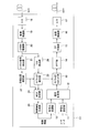
- FIG. 2 is a block diagram showing a main part of the internal configuration of the central processing unit CU.
- FIG. 3 is a block diagram showing a main part of the internal configuration of the antenna unit RAU.
- FIG. 4 is a block diagram showing the main part of the internal configuration of the mobile station MS.
- the central processing unit CU includes coded modulation units 10 and 11, a signal multiplexing unit 12, a subcarrier mapping unit 13, an IFFT unit 14, and a CP adding unit. 15, a transmission radio unit 16, an optical transmitter 17, an optical receiver 18, a reception radio unit 19, an OFDM demodulation unit 20, a pilot signal extraction unit 21, a reception quality measurement unit 22, a subcarrier allocation unit 23, an MCS determination unit 24, A control information generation unit 25 and a CQI extraction unit 26 are provided.
- the encoding modulation unit 10 performs predetermined error correction encoding on the control information including the bit data sequence, and further uses a predetermined modulation multilevel modulation scheme (for example, BPSK modulation, QPSK modulation) to generate a symbol data sequence. Generate a signal.
- a predetermined modulation multilevel modulation scheme for example, BPSK modulation, QPSK modulation
- Generate a signal as the coding rate and the modulation multi-level number when performing error correction coding, preset fixed values are used.
- control information is transmitted using a low coding rate by BPSK modulation or QPSK modulation because high-quality transmission is required.
- the encoding modulation unit 11 performs predetermined error correction encoding on user data composed of a bit data sequence, and further uses symbol data using a predetermined modulation multi-level modulation scheme (for example, QPSK, 16QAM, 64QAM modulation).
- a predetermined modulation multi-level modulation scheme for example, QPSK, 16QAM, 64QAM modulation.
- a series signal is generated and output to the signal multiplexer 12.
- the signal multiplexing unit 12 multiplexes the inputs from the encoding modulation unit 10 and the encoding modulation unit 11 and outputs the multiplexed data as a frequency data block to the subcarrier mapping unit 13.
- the subcarrier mapping unit 13 maps the frequency data block that is the output of the signal multiplexing unit 12 to a specific subcarrier (hereinafter referred to as subcarrier mapping), and outputs it to the IFFT unit 14. At this time, the subcarrier mapping unit 13 performs mapping using the subcarrier allocation information (number of subcarriers, subcarrier number, etc.) from the subcarrier allocation unit 23.
- An IFFT (Inverse Fast Fourier Transform) unit 14 performs an inverse fast Fourier transform on the output of the subcarrier mapping unit 13 and outputs the result to the CP adding unit 15.
- the CP adding unit 15 adds CP (Cyclic) to the transmission data input from the IFFT unit 14.
- a guard interval using Prefix) is inserted and output to the transmission radio unit 16.
- the transmission radio unit 16 outputs the transmission data from the CP adding unit 65 to the optical transmitter 17 by up-converting the baseband frequency to the radio frequency.
- the optical transmitter 17 optically modulates the radio signal (downlink signal) from the transmission radio unit 16 to convert it into an optical signal, and transmits it to each antenna unit RAU0 to RAUn through the optical fiber cable OC1.
- the optical receiver 18 receives an optical signal (a signal in which a radio signal is optical intensity modulated) transmitted from each of the antenna units RAU0 to RAUn through the optical fiber cable OC2, and uses the optical signal as an original radio signal (uplink signal). ).
- the reception radio unit 19 performs amplification processing, band limitation processing, and frequency conversion processing on the radio signal, and outputs the result as a complex baseband signal including an in-phase signal and a quadrature-phase signal.
- the OFDM demodulator 20 performs OFDM demodulation on each input baseband signal. That is, after time and frequency synchronization processing, GI (Guard Interval) removal, FFT (Fast Fourier Transform) processing, and serial-parallel conversion processing are performed.
- GI Guard Interval
- FFT Fast Fourier Transform
- the pilot signal extraction unit 21 extracts the pilot signal transmitted from the mobile station from the reception signal input from the OFDM demodulation unit 20 and outputs the pilot signal to the reception quality measurement unit 22.
- the CQI extraction unit 26 extracts channel quality information (CQI: Channel Quality Information) transmitted from the mobile station from the received signal input from the OFDM demodulation unit 20 and outputs the channel quality information (CQI) to the subcarrier allocation unit 23.
- CQI Channel Quality Information
- the reception quality measurement unit 22 measures the reception quality for each subcarrier based on the output of the pilot signal extraction unit 21. Specifically, the reception quality measurement unit 22 measures the reception quality for each subcarrier using the pilot signal from the pilot signal extraction unit 21 and outputs it to the subcarrier allocation unit 23. As this reception quality, CIR (Carrier to Interferer Ratio) or SIR (Signal to Interferer Ratio), SNR (Signal Use any measured value such as Noise Ratio).
- the subcarrier allocation unit 23 allocates uplink subcarriers from each mobile station using the reception quality for each subcarrier measured by the reception quality measurement unit 22 (allocates frequency resources). Specifically, the subcarrier allocation unit 23 sets the number of subcarriers, the subcarrier number, and the like as the subcarrier allocation information. Here, subcarriers with high reception quality from each mobile station are assigned to each mobile station. Then, the subcarrier allocation unit 23 outputs uplink subcarrier allocation information from each mobile station to the subcarrier mapping unit 13 and the MCS determination unit 24.
- the subcarrier allocation unit 23 allocates downlink subcarriers to each mobile station (allocates frequency resources) using the CQI of each subcarrier extracted by the CQI extraction unit 26. Specifically, the subcarrier allocation unit 23 sets the number of subcarriers, the subcarrier number, and the like as the subcarrier allocation information. Here, subcarriers with good CQI (higher quality) from each mobile station are assigned to each mobile station. Then, the subcarrier allocation unit 23 outputs the subcarrier allocation information for the downlink to each mobile station to the subcarrier mapping unit 13 and the MCS determination unit 24.
- the MCS determination unit 24 Based on the subcarrier allocation information from the subcarrier allocation unit 23 and the information on the reception quality of each subcarrier, the MCS determination unit 24 performs modulation modulation for each subcarrier or for each subcarrier block in which a plurality of subcarriers are set. MCS (Modulation and Coding Schemes) information such as the number of values and code rate is adaptively selected and output to the control information generation unit 25.
- the control information generation unit 25 generates a control signal including MCS information and subcarrier allocation information, and outputs the control signal to the encoding modulation unit 10 as control information.
- FIG. 3 shows only the internal configuration of antenna unit RAU0 among the plurality of antenna units RAU0 to RAUn, but other antenna units have the same configuration.
- the antenna unit RAU0 includes an antenna 30, a duplexer 31, an optical receiver 32, an amplifier 33 (for downlink signal), a filter 34 (for downlink signal), an amplifier 35 (for uplink signal), A filter 36 (for uplink signal) and an optical transmitter 37 are provided.
- the duplexer 31 (DPX) is provided to share the antenna 30 in the transmission / reception system.
- the optical receiver 32 receives an optical signal transmitted from the central processing unit CU through the optical fiber cable OC1 (a signal obtained by modulating a radio intensity of the radio signal), and demodulates the optical signal into an original radio signal.
- the filter 34 is set so that a band through which the radio signal (downlink signal) amplified by the amplifier 33 is transmitted is a predetermined transmission band that is a part of the system band.
- the radio signal received by the antenna 30 from the mobile station is amplified by the amplifier 35 and then input to the filter 36.
- the filter 36 is set so that the band that transmits the input radio signal (uplink signal) without being suppressed is a predetermined transmission band that is a part of the system band.
- the optical transmitter 37 converts the radio signal transmitted through the filter 36 into an optical signal by modulating the optical intensity, and outputs the optical signal to the central processing unit CU through the optical fiber cable OC2.
- the filters 34 and 36 are known BPFs (Band Pass Filters) and can be configured as digital filters or analog filters.
- the mobile station MS includes an antenna 50, a duplexer 51, a reception radio unit 52, an OFDM demodulation unit 53, a control information extraction unit 54, a demodulation / decoding unit 55, Carrier allocation information extraction unit 56, pilot signal extraction unit 57, MCS information extraction unit 58, CQI measurement unit 59, encoding modulation unit 60, encoding modulation unit 61, signal multiplexing unit 62, subcarrier mapping unit 63, IFFT unit 64 , A CP adding unit 65, a transmission radio unit 66, and a pilot signal generating unit 67.
- the duplexer 51 (DPX) is provided to share the antenna 50 in the transmission / reception system.
- the encoding / modulation unit 60 performs predetermined error correction coding on user data consisting of a bit data sequence, and further uses a predetermined modulation multi-level modulation scheme (for example, QPSK, 16QAM, 64QAM modulation) to generate symbols.
- a data series signal is generated and output to the signal multiplexing unit 62.
- the MCS information Modulation and Coding Schemes
- the MCS information extraction unit that extracts MCS information from a control signal transmitted from the central processing unit CU. 58 based on the output of 58. This setting enables adaptive modulation according to the propagation path condition.
- the encoding modulation unit 61 performs predetermined error correction encoding on the control information including the bit data sequence, and further uses a predetermined modulation multilevel modulation scheme (for example, BPSK modulation, QPSK modulation) to generate a symbol data sequence. Generate a signal.
- a predetermined modulation multilevel modulation scheme for example, BPSK modulation, QPSK modulation
- the coding rate and the modulation multi-level number used for error correction coding are fixed in advance.
- control information since control information requires high-quality transmission, it is transmitted using a low coding rate by BPSK modulation or QPSK modulation.
- the signal multiplexing unit 62 multiplexes the inputs from the encoding modulation units 60 and 61 and outputs the multiplexed data as a frequency data block to the subcarrier mapping unit 63.
- the subcarrier mapping unit 63 maps the frequency data block, which is the output of the signal multiplexing unit 62, to a specific subcarrier (hereinafter referred to as subcarrier mapping), and outputs it to the IFFT unit 64. At this time, the subcarrier mapping unit 63 performs mapping using the subcarrier allocation information (number of subcarriers, subcarrier number, etc.) extracted by the subcarrier allocation information extraction unit 56.
- the IFFT unit 64 performs inverse fast Fourier transform on the output of the subcarrier mapping unit 63 and outputs the result to the CP adding unit 65.
- CP adding section 65 inserts a guard interval using CP (Cyclic Prefix) into the transmission data input from IFFT section 64 and outputs the result to transmission radio section 66.
- the transmission radio unit 66 radiates the transmission data from the CP adding unit 65 from the antenna 50 to the space by up-converting the baseband frequency to the radio frequency.
- the reception radio unit 52 performs amplification processing, band limitation processing, and frequency conversion processing on the radio signal received by the antenna 50, and forms a complex baseband signal composed of an in-phase signal and a quadrature-phase signal. Output.
- the OFDM demodulator 53 performs OFDM demodulation on each input baseband signal. That is, after time and frequency synchronization processing, GI (Guard Interval) removal, FFT (Fast Fourier Transform) processing, and serial-parallel conversion processing are performed.
- GI Guard Interval
- FFT Fast Fourier Transform
- the control information extraction unit 54 extracts control information from the central processing unit CU from the received signal input from the OFDM demodulation unit 53 and outputs the control information to the demodulation and decoding unit 55.
- This control signal includes subcarrier allocation information, pilot signals, and MCS information.
- the subcarrier allocation information extraction unit 56, pilot signal extraction unit 57, and MCS information extraction unit 58 are subcarrier allocation information, pilot signal, and MCS, respectively, from the control information demodulated and decoded by the demodulation and decoding unit 55. Extract information.
- CQI measurement section 59 measures channel quality information (CQI) of each subcarrier based on the output of pilot signal extraction section 57. Specifically, CQI measurement unit 59 measures the CQI for each subcarrier using the pilot signal from pilot signal extraction unit 57 and outputs the CQI to signal multiplexing unit 62. CIR (Carrier based on pilot signal) as CQI to Interferer Ratio), SIR (Signal to Interferer Ratio), SNR (Signal to Noise) Any measured value such as Ratio) can be applied.
- the CQI of each subcarrier represents downlink signal quality for the mobile station.
- the CQI of each subcarrier is transmitted to the central processing unit CU, and is used for downlink subcarrier allocation to each mobile station.
- the pilot signal generator 67 generates a pilot signal that is a signal sequence that is known in advance for the central processing unit CU, and outputs the pilot signal to the signal multiplexer 62.
- the signal sequence used for the pilot signal is set based on the output of the pilot signal extraction unit 57.
- the antenna of the micro cell near the cell boundary or close to the cell boundary.
- the characteristics of the unit filter 34 (for downlink signals) are such that the transmission band transmitted without suppressing the downlink signal is different from the transmission bands of other antenna units belonging to different cells that are close to each other across the cell boundary. It is set not to overlap.
- the characteristics of the filter 36 (for uplink signal) of the antenna unit of the microcell in the vicinity of the cell boundary or in the vicinity of the cell boundary among the antenna units RAU0 to RAUn in the cell can suppress the uplink signal.
- the transmission band to be transmitted is set so as not to overlap with the transmission bands of other antenna units that are close to each other and belong to different cells across the cell boundary. That is, the filter characteristics of the proximity antenna units are set so as not to overlap.
- the filter characteristics are set in order to reduce inter-cell interference between the antenna unit and the mobile station at the cell boundary.
- interference is generally planned to be avoided by appropriate scheduling or the like.
- setting of a filter for interference of the communication link in the same cell is planned. Is not considered. For example, there is no restriction on the filter characteristics of antenna units that are close together in the same cell.
- filter setting FS1 a setting for suppressing (not completely blocking) a band other than the transmission band
- filter setting FS2 a setting for completely blocking a band other than the transmission band
- the filter 34 for downlink signal
- the filter setting FS2 the transmission power of a signal in a band other than the transmission band decreases in the antenna unit.
- the reach of is limited. That is, since radio waves do not reach the vicinity of the cell boundary, inter-cell interference (interference between downlink signals for each mobile station) is reduced unless the above-described transmission band overlap setting is made.
- the filter 36 for the uplink signal
- the filter setting FS1 a setting that does not completely cut off the band other than the transmission band
- the filter setting FS2 setting for completely blocking bands other than the transmission band
- the filter characteristics of the filter 34 (for downlink signal) and the filter 36 (for uplink signal) can be set separately according to the downlink band and the uplink band specified in the system, respectively. Further, a filter may be provided substantially only in either the downlink or the uplink (that is, either one is set to transmit all bands).
- FIG. 5 is a diagram illustrating the relationship between frequency and power spectral density (PSD) as a filter characteristic.
- FIG. 5A is a characteristic that transmits the entire system band (hereinafter referred to as a full band transmission characteristic)
- FIG. I s a characteristic of transmitting only the band F1 without being suppressed in the system band (hereinafter referred to as F1 band transmission characteristic)
- F1 band transmission characteristic a characteristic of transmitting only the band F2 of the system band without being suppressed
- F2 a characteristic of transmitting only the band F2 of the system band without being suppressed
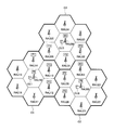
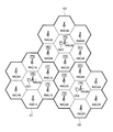
- FIG. 6 to 7 are diagrams showing the characteristics of the antenna unit RAU in three mutually adjacent cells C1 to C3. F0 to F3 described together with the antenna unit have filter characteristics of the antenna unit shown in FIG. a) to (d).
- the cell C1 is provided with a central processing unit CU1 and a plurality of antenna units RAU10 to RAU16.
- the central processing unit CU1 and each antenna unit are connected by an optical fiber cable (not shown).
- the cell C2 is provided with a central processing unit CU2 and a plurality of antenna units RAU20 to RAU26, and the central processing unit CU2 and each antenna unit are connected by an optical fiber cable (not shown).
- the cell C3 is provided with a central processing unit CU3 and a plurality of antenna units RAU30 to RAU36, and the central processing unit CU3 and each antenna unit are connected by an optical fiber cable (not shown).
- FIG. 6 is an example in which the filter characteristics of each antenna unit are set such that the filter characteristics of the antenna units existing at the cell boundary of the same cell are the same and the filter characteristics are different between different cells.
- the antenna units RAU12 to 14 belonging to the cell C1 are all set to the F1 band transmission characteristics
- the antenna units RAU24 to 26 belonging to the cell C2 are all set to the F2 band transmission characteristics
- 32 to 36 are all set to F3 band transmission characteristics.
- the transmission band of the proximity antenna unit of the adjacent micro cell across the cell boundary does not overlap (the above requirement A).
- the antenna units RAU 10, 20, and 30 at the center of each cell do not need to consider inter-cell interference, so there is no limitation on the filter characteristics (requirement B above), and here the full-band transmission characteristics are used.
- 7 and 8 are examples in which the filter characteristics of each antenna unit are set when the filter characteristics of the antenna units existing at the cell boundary of the same cell can be different for each microcell.
- the filter characteristic of the antenna unit RAU13 belonging to the cell C1 is the F1 band transmission characteristic
- the filter characteristic of the antenna unit RAU31 adjacent to the antenna unit RAU13 across the cell boundary is the F3 band transmission characteristic.
- the filter characteristics of the antenna unit RAU13 belonging to the cell C1 and the antenna unit RAU25 of the other cell C2 adjacent to the antenna unit RAU31 belonging to the cell C3 across the cell boundary are F2 band transmission characteristics.
- the antenna unit RAU14 of the cell C1 has the F3 band transmission characteristic as a filter characteristic different from the antenna unit RAU36 (F2 band transmission characteristic) that is adjacent to each other across the cell boundary.
- the antenna unit RAU14 has a filter characteristic that is different from the antenna unit RAU13 (F1 band transmission characteristic) that is adjacent in the same cell.
- the filter characteristics of other antenna units are set.
- the antenna units RAU 10, 20, and 30 at the center of each cell do not need to consider inter-cell interference, so there is no limitation on the filter characteristics (requirement B above), and here the full-band transmission characteristics are used.
- the filter characteristic of the antenna unit RAU13 belonging to the cell C1 is the F1 band transmission characteristic
- the filter characteristic of the antenna unit RAU31 adjacent to the antenna unit RAU13 across the cell boundary is the F2 band transmission characteristic.
- the filter characteristics of the antenna unit RAU13 belonging to the cell C1 and the antenna unit RAU25 of another cell C2 adjacent to the antenna unit RAU31 belonging to the cell C3 across the cell boundary are F3 band transmission characteristics.
- the antenna unit RAU14 of the cell C1 has the F2 band transmission characteristic as a filter characteristic different from the antenna unit RAU36 (F3 band transmission characteristic) that is adjacent to each other across the cell boundary.
- the antenna unit RAU14 has a filter characteristic that is different from the antenna unit RAU13 (F1 band transmission characteristic) that is adjacent in the same cell.
- the filter characteristics of other antenna units are set.
- the antenna units RAU 10, 20, and 30 at the center of each cell do not need to consider inter-cell interference, so there is no limitation on the filter characteristics (requirement B above), and here the full-band transmission characteristics are used.
- the antenna unit filters (for downlink signals and uplink signals) do not need to be provided for all antenna units in the cell, and are located near the cell boundary where they are severely positioned against inter-cell interference. It is only necessary to provide the antenna unit. Further, even when the filter is provided for all antenna units in the cell, it can be set so that the transmission band becomes wider as the distance from the cell boundary increases. This is because an antenna unit closer to the center of the cell is more advantageous for inter-cell interference.
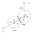
- FIG. 9 is a diagram illustrating communication between an antenna unit of a micro cell adjacent between cells and a mobile station.
- RAU 13 and RAU 31 (see FIG. 6 or FIG. 7) as an example of antenna units of microcells adjacent between cells, and central processing units CU1 and CU3 connected to each antenna unit by an optical fiber cable, Mobile stations MS1 and MS3 that perform wireless communication with each antenna unit are shown. Further, as shown in the figure, the filter characteristics of the antenna units RAU13 and RAU31 are an F1 band transmission characteristic and an F3 band transmission characteristic, respectively. In the following description, it is assumed that the higher the CQI value as quality information, the better (higher quality).
- the antenna unit RAU13 demodulates the optical signal transmitted from the central processing unit CU1 into an original radio signal, and performs filtering of F1 band transmission characteristics on the radio signal. Apply.
- the mobile station MS1 extracts a pilot signal included in each subcarrier and measures the CQI of each subcarrier.
- the CQI of the subcarrier corresponding to the band F1 becomes high, and the band F1 The CQI of the subcarriers in the bands other than is low.
- the CQI of each subcarrier measured by the mobile station MS1 is mapped to the uplink signal together with the pilot signal of each subcarrier and fed back to the central processing unit CU1.
- the central processing unit CU1 the CQI of each subcarrier is extracted based on the uplink signal from the mobile station MS1, and this CQI is reflected in the assignment of the downlink subcarrier to the mobile station MS1 (frequency resource assignment). Is done. In the example shown in FIG. 9, the CQI of the subcarrier corresponding to the band F1 is high, and the CQI of the subcarrier in the band other than the band F1 is low. For this reason, the central processing unit CU1 allocates subcarriers corresponding to the band F1 to the downlink addressed to the mobile station MS1.
- a subcarrier corresponding to the band F3 is assigned to the downlink addressed to the mobile station MS3. Accordingly, the subcarrier frequencies of the downlink signals for mobile stations MS1 and MS3 existing in different adjacent cells are separated from each other, and interference is avoided.
- inter-cell interference is suppressed even if frequency resources are not allocated on the central processing unit CU side. That is, in FIG. 9, the received signals of the mobile stations MS1 and MS3 are not related to the frequency resource allocation in the central processing unit CU because the bands other than the bands F1 and F3 are suppressed or blocked, respectively. , Downlink signal interference to the mobile stations MS1 and MS3 is suppressed. However, it is preferable to assign frequency resources by the central processing unit CU in order to reliably avoid interference because the subcarriers assigned to the mobile stations MS1 and MS3 are reliably distinguished.
- the mobile station MS1 maps the pilot signal of each subcarrier together with the CQI of each subcarrier to the uplink signal. Based on this pilot signal, the central processing unit CU1 measures (evaluates) the reception quality of each subcarrier of the uplink signal from the mobile station MS1. That is, the central processing unit CU1 extracts the pilot signal of each subcarrier from the uplink signal from the mobile station MS1, and based on this pilot signal, the reception quality (for example, signal power to interference power ratio) of each subcarrier. SIR) is measured.
- the reception quality for example, signal power to interference power ratio
- the measurement result of the reception quality of each subcarrier is reflected in the subcarrier allocation (frequency resource allocation) to the uplink from the mobile station MS1.
- the reception quality of subcarriers corresponding to the band F1 is high, and the reception quality of subcarriers in bands other than the band F1 is low.
- the central processing unit CU1 allocates subcarriers corresponding to the band F1 to the uplink from the mobile station MS1.
- the central processing unit CU3 allocates a subcarrier corresponding to the band F3 for the uplink from the mobile station MS3. Therefore, the subcarrier frequencies of the uplink signals from mobile stations MS1 and MS3 existing in different adjacent cells to each antenna unit are separated from each other, and interference is avoided.
- the filter characteristics of the filters (for uplink signals) of the antenna units RAU13 and RAU31 are preferably FS2 characteristics (setting for completely blocking bands other than the transmission band) as described above. Thereby, the inter-cell interference in the uplink from the mobile stations MS1 and MS3 is further reduced.
Landscapes
- Engineering & Computer Science (AREA)
- Computer Networks & Wireless Communication (AREA)
- Signal Processing (AREA)
- Mobile Radio Communication Systems (AREA)
Abstract
L'invention concerne un système de communication radio comprenant : une pluralité de dispositifs d'antennes distribués dans des cellules respectives pour réaliser une communication radio avec une station mobile ; et un dispositif de traitement de signaux connecté à chacun des dispositifs d'antennes. Des dispositifs d'antennes adjacents positionnés pour prendre en sandwich une frontière de cellule et appartenant à des cellules différentes ont des filtres ayant chacun une bande de transmission définie pour transmettre un signal de liaison descendante dans la bande de système sans supprimer le signal. Les bandes de transmission des filtres respectifs des dispositifs d'antennes adjacents sont définies de sorte que les bandes ne se recouvrent pas. Par conséquent, les bandes des signaux de liaison descendante provenant des dispositifs d'antennes adjacents vers une station mobile ne se recouvrent pas. Cela réduit les interférences intercellulaires de la liaison de flux descendant pour la station mobile dans le voisinage de la frontière de cellule.
Priority Applications (1)
| Application Number | Priority Date | Filing Date | Title |
|---|---|---|---|
| PCT/JP2008/003900 WO2010073293A1 (fr) | 2008-12-22 | 2008-12-22 | Système de communication radio et procédé de communication radio |
Applications Claiming Priority (1)
| Application Number | Priority Date | Filing Date | Title |
|---|---|---|---|
| PCT/JP2008/003900 WO2010073293A1 (fr) | 2008-12-22 | 2008-12-22 | Système de communication radio et procédé de communication radio |
Publications (1)
| Publication Number | Publication Date |
|---|---|
| WO2010073293A1 true WO2010073293A1 (fr) | 2010-07-01 |
Family
ID=42286965
Family Applications (1)
| Application Number | Title | Priority Date | Filing Date |
|---|---|---|---|
| PCT/JP2008/003900 Ceased WO2010073293A1 (fr) | 2008-12-22 | 2008-12-22 | Système de communication radio et procédé de communication radio |
Country Status (1)
| Country | Link |
|---|---|
| WO (1) | WO2010073293A1 (fr) |
Cited By (3)
| Publication number | Priority date | Publication date | Assignee | Title |
|---|---|---|---|---|
| JP2012065280A (ja) * | 2010-09-17 | 2012-03-29 | Mitsubishi Electric Corp | 無線通信システム、基地局および群ゲートウェイ |
| JP2012253496A (ja) * | 2011-06-01 | 2012-12-20 | Nippon Telegr & Teleph Corp <Ntt> | 無線通信システム及びセル・アンテナ配備パターン最適化装置及びプログラム |
| JP2014503136A (ja) * | 2010-11-22 | 2014-02-06 | サムスン エレクトロニクス カンパニー リミテッド | セルラー移動通信システムのアンテナ割り当て装置及び方法 |
Citations (4)
| Publication number | Priority date | Publication date | Assignee | Title |
|---|---|---|---|---|
| JPS6336624A (ja) * | 1985-07-31 | 1988-02-17 | ルーセント テクノロジーズ インコーポレイテッド | デジタル無線伝送系 |
| JPH09261726A (ja) * | 1996-03-22 | 1997-10-03 | Canon Inc | 無線通信システム |
| JP2001285244A (ja) * | 2000-03-30 | 2001-10-12 | Matsushita Electric Ind Co Ltd | Ofdm送信システム |
| JP2008523647A (ja) * | 2005-06-29 | 2008-07-03 | 株式会社東芝 | 無線通信システム |
-
2008
- 2008-12-22 WO PCT/JP2008/003900 patent/WO2010073293A1/fr not_active Ceased
Patent Citations (4)
| Publication number | Priority date | Publication date | Assignee | Title |
|---|---|---|---|---|
| JPS6336624A (ja) * | 1985-07-31 | 1988-02-17 | ルーセント テクノロジーズ インコーポレイテッド | デジタル無線伝送系 |
| JPH09261726A (ja) * | 1996-03-22 | 1997-10-03 | Canon Inc | 無線通信システム |
| JP2001285244A (ja) * | 2000-03-30 | 2001-10-12 | Matsushita Electric Ind Co Ltd | Ofdm送信システム |
| JP2008523647A (ja) * | 2005-06-29 | 2008-07-03 | 株式会社東芝 | 無線通信システム |
Cited By (4)
| Publication number | Priority date | Publication date | Assignee | Title |
|---|---|---|---|---|
| JP2012065280A (ja) * | 2010-09-17 | 2012-03-29 | Mitsubishi Electric Corp | 無線通信システム、基地局および群ゲートウェイ |
| JP2014503136A (ja) * | 2010-11-22 | 2014-02-06 | サムスン エレクトロニクス カンパニー リミテッド | セルラー移動通信システムのアンテナ割り当て装置及び方法 |
| US9484998B2 (en) | 2010-11-22 | 2016-11-01 | Samsung Electronics Co., Ltd | Antenna allocation apparatus and method for cellular mobile communication system |
| JP2012253496A (ja) * | 2011-06-01 | 2012-12-20 | Nippon Telegr & Teleph Corp <Ntt> | 無線通信システム及びセル・アンテナ配備パターン最適化装置及びプログラム |
Similar Documents
| Publication | Publication Date | Title |
|---|---|---|
| US9681479B2 (en) | Device-to-device communication management using macrocell communication resources | |
| US20210345379A1 (en) | Base Station Apparatus, Mobile Station Apparatus, Method for Mapping a Response Signal, and Method for Determining a Response Signal Resource | |
| CN107197524B (zh) | 用于发送窄带物联网用户设备上行数据的方法及装置 | |
| EP1408710B1 (fr) | Appareil et procédé d'allocation de ressources d'une cellule virtuelle dans un système de communication mobile OFDM | |
| CA2770993C (fr) | Procede et appareil d'allocation d'une ressource de canal de commande d'un nud de relais dans une sous-trame de liaison de raccordement | |
| CN104038329B (zh) | 异构无线通信网络中的控制和数据信令 | |
| US7978662B2 (en) | Method and apparatus for transmitting/receiving downlink data for UE in soft handover region in an OFDM system | |
| KR101790040B1 (ko) | 무선 통신 시스템에서 전용 기준 신호를 위한 제어 채널 전송 방법 및 장치 | |
| US8868122B2 (en) | User apparatus, base station apparatus and communication control method | |
| CN116134934A (zh) | 具有降低的控制开销的多小区调度 | |
| US9591628B2 (en) | Base station apparatus and communication control method | |
| US8761275B2 (en) | Wireless communication apparatus and method for wireless communication | |
| US9439181B2 (en) | Radio communication system, radio base station apparatus, user terminal, and radio communication method | |
| EP2966893A1 (fr) | Station de base sans fil, terminal utilisateur, et procédé de communication sans fil | |
| WO2014192305A1 (fr) | Système de communication, stations de base, et procédé de contrôle de communications | |
| US20090285174A1 (en) | Communication terminal apparatus, control station, and multicarrier communication method | |
| JP5083253B2 (ja) | 無線送信装置、無線受信装置および送信方法 | |
| JP5187403B2 (ja) | 無線通信システム、基地局、リレー局、移動局 | |
| JP5131227B2 (ja) | 無線送信装置、無線受信装置および送信方法 | |
| WO2010073293A1 (fr) | Système de communication radio et procédé de communication radio | |
| KR20070034905A (ko) | 광대역 무선 접속 통신 시스템에서 주파수 자원 운용 장치및 방법 | |
| JP2008042861A (ja) | 通信システム、端末装置、基地局、及び通信方法 | |
| JP2014232991A (ja) | 通信システム、基地局、及び通信制御方法 | |
| CN113940040B (zh) | 通信装置 | |
| JP2014232996A (ja) | 通信システム、基地局、及び通信制御方法 |
Legal Events
| Date | Code | Title | Description |
|---|---|---|---|
| 121 | Ep: the epo has been informed by wipo that ep was designated in this application |
Ref document number: 08879092 Country of ref document: EP Kind code of ref document: A1 |
|
| NENP | Non-entry into the national phase |
Ref country code: DE |
|
| 122 | Ep: pct application non-entry in european phase |
Ref document number: 08879092 Country of ref document: EP Kind code of ref document: A1 |
|
| NENP | Non-entry into the national phase |
Ref country code: JP |