WO2010077008A2 - Procede d'etalonnage d'un instrument destine a un systeme de navigation medicale - Google Patents
Procede d'etalonnage d'un instrument destine a un systeme de navigation medicale Download PDFInfo
- Publication number
- WO2010077008A2 WO2010077008A2 PCT/KR2009/007712 KR2009007712W WO2010077008A2 WO 2010077008 A2 WO2010077008 A2 WO 2010077008A2 KR 2009007712 W KR2009007712 W KR 2009007712W WO 2010077008 A2 WO2010077008 A2 WO 2010077008A2
- Authority
- WO
- WIPO (PCT)
- Prior art keywords
- tool
- indicator
- magnetic sensor
- end point
- surgical navigation
- Prior art date
- Legal status (The legal status is an assumption and is not a legal conclusion. Google has not performed a legal analysis and makes no representation as to the accuracy of the status listed.)
- Ceased
Links
Images




Classifications
-
- A—HUMAN NECESSITIES
- A61—MEDICAL OR VETERINARY SCIENCE; HYGIENE
- A61B—DIAGNOSIS; SURGERY; IDENTIFICATION
- A61B17/00—Surgical instruments, devices or methods
-
- A—HUMAN NECESSITIES
- A61—MEDICAL OR VETERINARY SCIENCE; HYGIENE
- A61B—DIAGNOSIS; SURGERY; IDENTIFICATION
- A61B34/00—Computer-aided surgery; Manipulators or robots specially adapted for use in surgery
- A61B34/20—Surgical navigation systems; Devices for tracking or guiding surgical instruments, e.g. for frameless stereotaxis
-
- A—HUMAN NECESSITIES
- A61—MEDICAL OR VETERINARY SCIENCE; HYGIENE
- A61B—DIAGNOSIS; SURGERY; IDENTIFICATION
- A61B17/00—Surgical instruments, devices or methods
- A61B2017/00681—Aspects not otherwise provided for
- A61B2017/00725—Calibration or performance testing
-
- A—HUMAN NECESSITIES
- A61—MEDICAL OR VETERINARY SCIENCE; HYGIENE
- A61B—DIAGNOSIS; SURGERY; IDENTIFICATION
- A61B34/00—Computer-aided surgery; Manipulators or robots specially adapted for use in surgery
- A61B34/20—Surgical navigation systems; Devices for tracking or guiding surgical instruments, e.g. for frameless stereotaxis
- A61B2034/2046—Tracking techniques
- A61B2034/2051—Electromagnetic tracking systems
-
- A—HUMAN NECESSITIES
- A61—MEDICAL OR VETERINARY SCIENCE; HYGIENE
- A61B—DIAGNOSIS; SURGERY; IDENTIFICATION
- A61B34/00—Computer-aided surgery; Manipulators or robots specially adapted for use in surgery
- A61B34/20—Surgical navigation systems; Devices for tracking or guiding surgical instruments, e.g. for frameless stereotaxis
- A61B2034/2068—Surgical navigation systems; Devices for tracking or guiding surgical instruments, e.g. for frameless stereotaxis using pointers, e.g. pointers having reference marks for determining coordinates of body points
- A61B2034/207—Divots for calibration
Definitions
- the present disclosure relates to a method for calibrating a surgical navigation apparatus as a whole, and more particularly, to a method for calibrating a surgical navigation apparatus using a magnetic field to calibrate a surgical tool used in a surgical navigation apparatus. will be.
- FIG. 1 is a view for explaining an example of a method for calibrating a surgical navigation apparatus tool described in US Pat. No. 5,921,992, which includes infrared reflectors 21, 22, 23, 24 recognizable by the infrared camera 1.
- the tube 25 has a direction axis indicated by a dotted line 30, and has an end point indicated by 29 at its end, and the end point 29 and the direction axis 30 of the tube 25 are infrared reflectors 21, 22, 23, Relative to 24).
- the information collected by the infrared camera 1 is sent to the surgical navigation device 6, which is a computer, processed by the surgical navigation device 6, and displayed on the monitor 7.
- the surgical navigation apparatus 6 stores an image acquired through an MRI or CT apparatus, etc. prior to surgery, and refers to a device for displaying an area of interest among the images through the monitor 7 during surgery. At this time, the region of interest is recognized by the surgical navigation device 6, or a tool used for treating the affected part is a surgical tool or a tool 28.
- the instrument 28 may be referred to the infrared reflectors 32, 33, 34 of the instrument 28 or the coordinate system they form.
- Information about the direction 27 and its end point (corresponding to the end point 29) that the device has, and the position and the direction information about the infrared reflectors 21, 22, 23 and 24 or the coordinate system that they form It can be easily obtained by inserting the tool 28 to the end point 29 of the known tube 25.
- the tool 28 is inserted into the tube 25 and guided so that the end point of the tool 28 coincides with the endpoint 29 so that the direction 27 of the tool 28 coincides with the direction axis 30. do. Since the coordinates of the end point 29 and the direction axis 30 are already known, the coordinates of the direction 27 and the end point of the tool 28 are also known to the surgical navigation apparatus 6 through the infrared camera 1. .
- an infrared camera 1 that is, an optical sensor
- an infrared camera in case of being covered by a doctor or surgical device even in a field of view 8 of the infrared camera 1)
- the infrared reflector 21, 22, 23, 24
- the infrared reflector 32, 33, 34
- the surgical navigation device (6) is not working properly. This may be especially the case, for example, in dental surgery where surgery is performed in the mouth.
- FIG. 2 is a view conceptually explaining the meaning of the instrument calibration in the surgical navigation device.
- the surgical navigation device 6 includes the infrared reflectors 21, 22, 23, and 24 in one coordinate system (X1, Y1, Z1). ), And the infrared reflectors 32, 33, 34 are recognized as one coordinate system (X2, Y2, Z2).
- Tool calibration can be understood as the operation of indicating the direction 27 of the tool 28 and the end point (corresponding to the end point 29) of the tool with respect to the coordinate systems X2, Y2 and Z2.
- the relationship between 27 and the end point can be easily seen by placing the tool 28 at the end point 29 of the tube 25. That is, since the relationship between the end point 29 and the direction 30 of the tube 25 with respect to the coordinate system X1, Y1, Z1 is known, a linear transformation T is performed on the coordinate system X2, Y2, Z2. It is possible to express the relationship between the end point and the direction 27 of the tool 28 with respect to
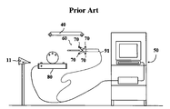
- FIG. 3 and 4 are views showing an example of a surgical navigation device and a tool described in US Patent No. 6,235,038, the surgical navigation device 50 is an operating table 80 equipped with a magnetic field generator in addition to the infrared camera 40 ),
- the tool 60 also has a magnetic sensor 90 (see FIG. 4) in addition to the infrared reflector 70, the magnetic sensor 90 consisting of a coil 92.
- the magnetic field generated by the magnetic field generator provided on the operating table 80 is sensed by the magnetic sensor 90, and is transmitted to the surgical navigation device 50 through the wireline 91. In the case of using such a magnetic sensor, it is possible to detect the tool 60 in the magnetic field irrespective of the doctor's disturbance.
- Reference numeral 11 denotes a reference frame.
- an instrument having a second magnetic sensor is provided using a calibrator having a first magnetic sensor, a first indicator, and a second indicator.
- a method of calibrating a surgical navigation device tool for recognizing a surgical navigation device comprising: a first step of associating a first magnetic sensor with a first indicator using the tool and a first indicator; And a second step of associating the tool located on the second indicator with the first indicator using the tool and the second indicator.
- a method of calibrating a tool for a surgical navigation device is provided. .
- the first indicator may be formed on one side (eg, the upper surface) of the calibrator itself, or may be formed on one side and three grooves so that the plane is recognizable, and the second indicator has a direction axis and an end point. It may consist of a hole or tube.
- FIG. 2 conceptually illustrates the meaning of instrument calibration in a surgical navigation device
- FIG 3 and 4 is a view showing an example of a surgical navigation apparatus and tools described in US Patent No. 6,235,038,
- FIG. 5 is a view showing an example of a calibrator according to the present disclosure.
- 6 and 7 illustrate an example of a method for calibrating a tool for surgical navigation apparatus in accordance with the present disclosure.
- FIG. 5 is a diagram illustrating an example of a calibrator according to the present disclosure.
- the calibrator 100 includes an upper surface 110, and is used for position recognition of the calibrator 100, and includes a magnetic sensor for calibrator having a coil 210. 200.
- the upper surface 110 is formed with a tool guide 116 of one hole or tube having three grooves 111, 112 and 113, an end point 114 and a direction axis 115, and three grooves 111, 112 and 113 and an end point ( 114) and the positional relationship (or coordinate relationship) of the direction axis 115 are known.
- the difference between using an optical sensor and a magnetic sensor is that in the case of an optical sensor (see FIG. 1), the infrared reflectors 21, 22, 23, 24 and the end point 29 and the direction of the tube 25 are oriented.
- the relationship between the axis 30 can be known in advance. That is, since the infrared reflectors 21, 22, 23, and 24 also exist on the base 20 so that they can be measured, the relationship between them can be known in advance.
- the magnetic sensor 200 having the coil 210 it is difficult to specify the positional relationship in advance due to the characteristics of the magnetic sensor.
- the present disclosure provides a calibration method that removes this limitation.
- the end points 114 of the grooves 111, 112, 113 and the tool guide 116 with respect to the coordinate axes X1, Y1, and Z1 formed by the magnetic sensor 200 for the calibrator.
- the relationship of the direction axis 115 is unknown.
- the positional relationship between the grooves 111, 112 and 113 and the end point 114 / direction axis 115 of the tool guide 116 is already known. Since this is information necessary for the manufacturing process of the braces 100, it is natural.
- the relationship between the coordinate axis (X1, Y1, Z1) and the coordinate axis (X2, Y2, Z2), that is, the linear transformation (T) is the surgical navigation device is a magnetic sensor for the calibrator 200 and a magnetic sensor for tools 310 to be described later; (See Fig. 6).
- the plane formed by the grooves 111, 112, and 113 in the straightener 100 and the direction axis 115 are orthogonal to each other, and the position of the grooves 111, 112, and 113 and the end point 114, that is, the distance relationship is given.
- the plane and the direction axis 115 do not necessarily have to be orthogonal, and it is sufficient to know the relationship with each other.
- FIGS. 6 and 7 are diagrams illustrating an example of a method for calibrating a tool for surgical navigation apparatus according to the present disclosure.
- the tool 300 having the magnetic sensor 310, the end point 320 and the direction 330 pointed by the tool 300 is inserted into the groove 111 of the calibrator 100. Rotate as indicated by the arrow. This is called pivoting, and the surgical navigation apparatus may specify the groove 111 from the magnetic sensor 310 or the coordinate systems X2, Y2, and Z2 that are pivoted, and also the coordinate system of the magnetic sensor 200. It can be recognized as a point for (X1, Y1, Z1). This pivoting is also performed for the grooves 112 and 113.
- the positional relationship of the end point 320 with respect to the coordinate system X2, Y2, Z2 can be determined by pivoting on the groove 111, the positional relationship of the grooves 112,113 with respect to the coordinate system X1, Y1, Z1. Can be recognized by simply placing the end point 320 in the grooves 112 and 113. Through this pivoting, information about the grooves 111, 112, and 113 can be obtained, and from this, the plane (or plane equation) formed by the grooves 111, 112, and 113 can be displayed with respect to the coordinate systems X1, Y1, and Z1.
- a plane can be obtained means that a direction perpendicular to the plane can be obtained, and thus the direction axis 115 of the tool guide 116 (see FIG. 5) perpendicular to the plane formed by the grooves 111, 112, and 113 is referred to. ) Is available.
- the end point 320 of the tool 300 is fixed to one point of the upper surface 110 (see FIG. 5) of the calibrator 100 (a slight error may occur).
- the position of the end point 320 with respect to the coordinate system X2, Y2, Z2 can be determined, and the tool 300 is then moved along the upper surface 110 (for example, by drawing an X letter to form a plane).
- the upper surface 110 can be recognized with respect to the coordinate system X1, Y1, Z1. In this case, the upper surface 110 can be utilized as a plane.
- the surgical navigation device is a relationship between the coordinate system (X1, Y1, Z1; posture of the magnetic sensor 200) and the coordinate system (X2, Y2, Z2; posture of the magnetic sensor 310), that is, linear transformation (T1). Can be identified.
- the direction 330 of the tool 300 becomes the direction of the direction axis 115, and the direction axis 115 with respect to the coordinate system X1, Y1, and Z1 is known to the surgical navigation apparatus, and thus, the linear transformation (T1).
- the direction 330 can be represented with respect to the coordinate systems X2, Y2 and Z2.
- the endpoint 320 is determined by the linear transformation T1. It can be expressed as (X2, Y2, Z2).
- the surgical navigation apparatus can recognize the end point 320 and the direction 330 of the tool 300 as values for the coordinate systems X2, Y2, and Z2 (the posture of the magnetic sensor 310).
- a method of calibrating a tool for surgical navigation apparatus that can calibrate a surgical tool using a magnetic sensor.
- a method of calibrating a tool for surgical navigation apparatus that is capable of calibrating a surgical tool (for example, a dental drill) having a detachable endpoint and having a magnetic sensor.
- a surgical tool for example, a dental drill
- the calibration is performed in a state where the end point is removed, and then the calibration is performed again in a state where the end point is attached, whereby the length of the detachable tool part can be determined.
Landscapes
- Health & Medical Sciences (AREA)
- Surgery (AREA)
- Life Sciences & Earth Sciences (AREA)
- Engineering & Computer Science (AREA)
- Molecular Biology (AREA)
- Biomedical Technology (AREA)
- Heart & Thoracic Surgery (AREA)
- Medical Informatics (AREA)
- Nuclear Medicine, Radiotherapy & Molecular Imaging (AREA)
- Animal Behavior & Ethology (AREA)
- General Health & Medical Sciences (AREA)
- Public Health (AREA)
- Veterinary Medicine (AREA)
- Robotics (AREA)
- Dental Tools And Instruments Or Auxiliary Dental Instruments (AREA)
- Magnetic Resonance Imaging Apparatus (AREA)
- Surgical Instruments (AREA)
Abstract
L'invention concerne un procédé permettant d'étalonner un instrument destiné à un système de navigation médicale, le système pouvant ainsi reconnaître l'instrument doté d'un second capteur magnétique utilisant un étalonneur doté d'un premier capteur magnétique, un premier marqueur de repère, et un second marqueur de repère, ledit procédé consistant: en premier lieu à associer le premier capteur magnétique au premier marqueur de repère à l'aide de l'instrument et le premier marqueur de repère; et en second lieu à associer l'instrument placé sur le second marqueur de repère au premier marqueur de repère à l'aide de l'instrument et du second marqueur de repère.
Applications Claiming Priority (2)
| Application Number | Priority Date | Filing Date | Title |
|---|---|---|---|
| KR10-2008-0138603 | 2008-12-31 | ||
| KR1020080138603A KR100996826B1 (ko) | 2008-12-31 | 2008-12-31 | 수술용 항법 장치용 도구의 교정 방법 |
Publications (2)
| Publication Number | Publication Date |
|---|---|
| WO2010077008A2 true WO2010077008A2 (fr) | 2010-07-08 |
| WO2010077008A3 WO2010077008A3 (fr) | 2010-10-07 |
Family
ID=42310333
Family Applications (1)
| Application Number | Title | Priority Date | Filing Date |
|---|---|---|---|
| PCT/KR2009/007712 Ceased WO2010077008A2 (fr) | 2008-12-31 | 2009-12-23 | Procede d'etalonnage d'un instrument destine a un systeme de navigation medicale |
Country Status (2)
| Country | Link |
|---|---|
| KR (1) | KR100996826B1 (fr) |
| WO (1) | WO2010077008A2 (fr) |
Cited By (8)
| Publication number | Priority date | Publication date | Assignee | Title |
|---|---|---|---|---|
| WO2011025708A3 (fr) * | 2009-08-31 | 2011-06-30 | Medtronic, Inc. | Système de localisation combiné |
| US9008757B2 (en) | 2012-09-26 | 2015-04-14 | Stryker Corporation | Navigation system including optical and non-optical sensors |
| EP3315089A1 (fr) * | 2016-10-25 | 2018-05-02 | Biosense Webster (Israel) Ltd. | Enregistrement de tête à l'aide d'une pince de préhension personnalisée |
| WO2019090703A1 (fr) * | 2017-11-10 | 2019-05-16 | 唐佩福 | Dispositif d'étalonnage |
| WO2020261003A1 (fr) * | 2019-06-26 | 2020-12-30 | DePuy Synthes Products, Inc. | Étalonnage d'instrument |
| CN116077179A (zh) * | 2021-11-08 | 2023-05-09 | 北京天智航医疗科技股份有限公司 | 手术器械注册的方法、电子设备及计算机可读存储介质 |
| CN116972730A (zh) * | 2023-05-06 | 2023-10-31 | 广东花至美容科技有限公司 | 人脸区域定位方法、装置及可穿戴设备、美护系统 |
| CN116999165A (zh) * | 2023-09-14 | 2023-11-07 | 春风化雨(苏州)智能医疗科技有限公司 | 用于骨科手术机器人电磁定位导航的参考架和其校准方法 |
Families Citing this family (2)
| Publication number | Priority date | Publication date | Assignee | Title |
|---|---|---|---|---|
| KR102145767B1 (ko) * | 2019-02-25 | 2020-08-19 | 재단법인 오송첨단의료산업진흥재단 | 수술항법 장치 평가용 팬텀 |
| KR102258825B1 (ko) * | 2019-04-29 | 2021-05-31 | (주)레벨소프트 | 위치가 추적되는 의료용 기구를 검측하는 장치 및 방법 |
Family Cites Families (5)
| Publication number | Priority date | Publication date | Assignee | Title |
|---|---|---|---|---|
| JPH0871086A (ja) * | 1994-09-06 | 1996-03-19 | Shimadzu Corp | 手術器具の位置表示装置 |
| US6611141B1 (en) | 1998-12-23 | 2003-08-26 | Howmedica Leibinger Inc | Hybrid 3-D probe tracked by multiple sensors |
| US6497134B1 (en) | 2000-03-15 | 2002-12-24 | Image Guided Technologies, Inc. | Calibration of an instrument |
| US8082020B2 (en) * | 2006-08-07 | 2011-12-20 | Biosense Webster, Inc. | Distortion-immune position tracking using redundant magnetic field measurements |
| KR100880403B1 (ko) | 2007-04-27 | 2009-01-23 | 주식회사 사이버메드 | 수술용 항법 장치의 작동 방법 |
-
2008
- 2008-12-31 KR KR1020080138603A patent/KR100996826B1/ko active Active
-
2009
- 2009-12-23 WO PCT/KR2009/007712 patent/WO2010077008A2/fr not_active Ceased
Cited By (16)
| Publication number | Priority date | Publication date | Assignee | Title |
|---|---|---|---|---|
| WO2011025708A3 (fr) * | 2009-08-31 | 2011-06-30 | Medtronic, Inc. | Système de localisation combiné |
| US11529198B2 (en) | 2012-09-26 | 2022-12-20 | Stryker Corporation | Optical and non-optical sensor tracking of objects for a robotic cutting system |
| US9008757B2 (en) | 2012-09-26 | 2015-04-14 | Stryker Corporation | Navigation system including optical and non-optical sensors |
| US9271804B2 (en) | 2012-09-26 | 2016-03-01 | Stryker Corporation | Method for tracking objects using optical and non-optical sensors |
| US9687307B2 (en) | 2012-09-26 | 2017-06-27 | Stryker Corporation | Navigation system and method for tracking objects using optical and non-optical sensors |
| US12144565B2 (en) | 2012-09-26 | 2024-11-19 | Stryker Corporation | Optical and non-optical sensor tracking of a robotically controlled instrument |
| US10575906B2 (en) | 2012-09-26 | 2020-03-03 | Stryker Corporation | Navigation system and method for tracking objects using optical and non-optical sensors |
| EP3315089A1 (fr) * | 2016-10-25 | 2018-05-02 | Biosense Webster (Israel) Ltd. | Enregistrement de tête à l'aide d'une pince de préhension personnalisée |
| WO2019090703A1 (fr) * | 2017-11-10 | 2019-05-16 | 唐佩福 | Dispositif d'étalonnage |
| WO2020261003A1 (fr) * | 2019-06-26 | 2020-12-30 | DePuy Synthes Products, Inc. | Étalonnage d'instrument |
| US11839434B2 (en) | 2019-06-26 | 2023-12-12 | DePuy Synthes Products, Inc. | Instrument calibration |
| US12402957B2 (en) | 2019-06-26 | 2025-09-02 | DePuy Synthes Products, Inc. | Instrument calibration |
| CN116077179A (zh) * | 2021-11-08 | 2023-05-09 | 北京天智航医疗科技股份有限公司 | 手术器械注册的方法、电子设备及计算机可读存储介质 |
| CN116972730A (zh) * | 2023-05-06 | 2023-10-31 | 广东花至美容科技有限公司 | 人脸区域定位方法、装置及可穿戴设备、美护系统 |
| CN116999165A (zh) * | 2023-09-14 | 2023-11-07 | 春风化雨(苏州)智能医疗科技有限公司 | 用于骨科手术机器人电磁定位导航的参考架和其校准方法 |
| WO2025055941A1 (fr) * | 2023-09-14 | 2025-03-20 | 春风化雨(苏州)智能医疗科技有限公司 | Référentiel de navigation de positionnement électromagnétique d'un robot de chirurgie orthopédique et son procédé d'étalonnage |
Also Published As
| Publication number | Publication date |
|---|---|
| WO2010077008A3 (fr) | 2010-10-07 |
| KR100996826B1 (ko) | 2010-11-26 |
| KR20100079991A (ko) | 2010-07-08 |
Similar Documents
| Publication | Publication Date | Title |
|---|---|---|
| KR100996826B1 (ko) | 수술용 항법 장치용 도구의 교정 방법 | |
| JP4757142B2 (ja) | 撮影環境校正方法及び情報処理装置 | |
| EP2335553A1 (fr) | Système d'équipement médical et procédé d'étalonnage de l'instrument médical | |
| US9572539B2 (en) | Device and method for determining the position of an instrument in relation to medical images | |
| JP5146692B2 (ja) | 光学的位置測定ならびに剛性または半可撓性の針の標的への誘導のためのシステム | |
| JP2010522573A5 (ja) | 光学的位置測定ならびに剛性または半可撓性の針の標的への誘導のためのシステム | |
| JP5137033B2 (ja) | 手術支援情報表示装置、手術支援情報表示方法及び手術支援情報表示プログラム | |
| KR101491922B1 (ko) | 하이브리드 내비게이션 시스템 및 그의 위치 추적 방법 | |
| US10702343B2 (en) | Medical instrumentation including a navigation system | |
| US11540706B2 (en) | Method of using a manually-operated light plane generating module to make accurate measurements of the dimensions of an object seen in an image taken by an endoscopic camera | |
| US10846883B2 (en) | Method for calibrating objects in a reference coordinate system and method for tracking objects | |
| JP5561458B2 (ja) | 手術支援システム | |
| US12183038B2 (en) | Camera calibration using fiducial markers on surgical tools | |
| CN113349929B (zh) | 用于髓内钉远端锁定孔的空间定位系统 | |
| US20250185885A1 (en) | Visualization system comprising an observation apparatus and an endoscope | |
| CN111265299B (zh) | 基于光纤形状传感的手术导航系统 | |
| US20230252681A1 (en) | Method of medical calibration | |
| JP2006187385A (ja) | 内視鏡装置及びその接触位置取得方法 | |
| WO2010061293A2 (fr) | Système et procédé pour mesurer des objets vus à travers une caméra | |
| KR101367366B1 (ko) | 영상 유도 수술을 위한 수술 도구를 보정하는 방법 및 도구 | |
| KR101544712B1 (ko) | 수술용 항법 시스템의 교정 방법 | |
| JP5213201B2 (ja) | 体内挿入器具の種類を識別可能な手術支援システム | |
| WO2017170488A1 (fr) | Système de mesure de position d'axe optique, procédé de mesure de position d'axe optique, programme de mesure de position d'axe optique et dispositif de mesure de position d'axe optique | |
| US20170339393A1 (en) | Method for registering a patient coordinate system using an image data coordinate system | |
| JPH09166410A (ja) | 位置計測装置 |
Legal Events
| Date | Code | Title | Description |
|---|---|---|---|
| 121 | Ep: the epo has been informed by wipo that ep was designated in this application |
Ref document number: 09836329 Country of ref document: EP Kind code of ref document: A2 |
|
| NENP | Non-entry into the national phase |
Ref country code: DE |
|
| 122 | Ep: pct application non-entry in european phase |
Ref document number: 09836329 Country of ref document: EP Kind code of ref document: A2 |