WO2010084940A1 - 可動子及びリニアモータ - Google Patents
可動子及びリニアモータ Download PDFInfo
- Publication number
- WO2010084940A1 WO2010084940A1 PCT/JP2010/050761 JP2010050761W WO2010084940A1 WO 2010084940 A1 WO2010084940 A1 WO 2010084940A1 JP 2010050761 W JP2010050761 W JP 2010050761W WO 2010084940 A1 WO2010084940 A1 WO 2010084940A1
- Authority
- WO
- WIPO (PCT)
- Prior art keywords
- flat
- inner yoke
- magnetized
- magnets
- yoke
- Prior art date
- Legal status (The legal status is an assumption and is not a legal conclusion. Google has not performed a legal analysis and makes no representation as to the accuracy of the status listed.)
- Ceased
Links
Images


Classifications
-
- H—ELECTRICITY
- H02—GENERATION; CONVERSION OR DISTRIBUTION OF ELECTRIC POWER
- H02K—DYNAMO-ELECTRIC MACHINES
- H02K41/00—Propulsion systems in which a rigid body is moved along a path due to dynamo-electric interaction between the body and a magnetic field travelling along the path
- H02K41/02—Linear motors; Sectional motors
-
- H—ELECTRICITY
- H02—GENERATION; CONVERSION OR DISTRIBUTION OF ELECTRIC POWER
- H02K—DYNAMO-ELECTRIC MACHINES
- H02K1/00—Details of the magnetic circuit
- H02K1/06—Details of the magnetic circuit characterised by the shape, form or construction
- H02K1/22—Rotating parts of the magnetic circuit
- H02K1/27—Rotor cores with permanent magnets
- H02K1/2706—Inner rotors
- H02K1/272—Inner rotors the magnetisation axis of the magnets being perpendicular to the rotor axis
- H02K1/274—Inner rotors the magnetisation axis of the magnets being perpendicular to the rotor axis the rotor consisting of two or more circumferentially positioned magnets
- H02K1/2753—Inner rotors the magnetisation axis of the magnets being perpendicular to the rotor axis the rotor consisting of two or more circumferentially positioned magnets the rotor consisting of magnets or groups of magnets arranged with alternating polarity
- H02K1/278—Surface mounted magnets; Inset magnets
-
- H—ELECTRICITY
- H02—GENERATION; CONVERSION OR DISTRIBUTION OF ELECTRIC POWER
- H02K—DYNAMO-ELECTRIC MACHINES
- H02K41/00—Propulsion systems in which a rigid body is moved along a path due to dynamo-electric interaction between the body and a magnetic field travelling along the path
- H02K41/02—Linear motors; Sectional motors
- H02K41/03—Synchronous motors; Motors moving step by step; Reluctance motors
- H02K41/031—Synchronous motors; Motors moving step by step; Reluctance motors of the permanent magnet type
-
- H—ELECTRICITY
- H02—GENERATION; CONVERSION OR DISTRIBUTION OF ELECTRIC POWER
- H02K—DYNAMO-ELECTRIC MACHINES
- H02K1/00—Details of the magnetic circuit
- H02K1/06—Details of the magnetic circuit characterised by the shape, form or construction
- H02K1/12—Stationary parts of the magnetic circuit
- H02K1/14—Stator cores with salient poles
- H02K1/146—Stator cores with salient poles consisting of a generally annular yoke with salient poles
-
- H—ELECTRICITY
- H02—GENERATION; CONVERSION OR DISTRIBUTION OF ELECTRIC POWER
- H02K—DYNAMO-ELECTRIC MACHINES
- H02K2207/00—Specific aspects not provided for in the other groups of this subclass relating to arrangements for handling mechanical energy
- H02K2207/03—Tubular motors, i.e. rotary motors mounted inside a tube, e.g. for blinds
-
- H—ELECTRICITY
- H02—GENERATION; CONVERSION OR DISTRIBUTION OF ELECTRIC POWER
- H02K—DYNAMO-ELECTRIC MACHINES
- H02K2213/00—Specific aspects, not otherwise provided for and not covered by codes H02K2201/00 - H02K2211/00
- H02K2213/03—Machines characterised by numerical values, ranges, mathematical expressions or similar information
-
- H—ELECTRICITY
- H02—GENERATION; CONVERSION OR DISTRIBUTION OF ELECTRIC POWER
- H02K—DYNAMO-ELECTRIC MACHINES
- H02K29/00—Motors or generators having non-mechanical commutating devices, e.g. discharge tubes or semiconductor devices
- H02K29/03—Motors or generators having non-mechanical commutating devices, e.g. discharge tubes or semiconductor devices with a magnetic circuit specially adapted for avoiding torque ripples or self-starting problems
-
- H—ELECTRICITY
- H02—GENERATION; CONVERSION OR DISTRIBUTION OF ELECTRIC POWER
- H02K—DYNAMO-ELECTRIC MACHINES
- H02K7/00—Arrangements for handling mechanical energy structurally associated with dynamo-electric machines, e.g. structural association with mechanical driving motors or auxiliary dynamo-electric machines
- H02K7/08—Structural association with bearings
Definitions
- the present invention relates to a mover in which a plurality of flat permanent magnets are provided on the outer surface of a rectangular inner yoke, and a linear motor formed by combining the mover and an armature (stator).
- linear motors have a faster response than ball screws, but because the mass of the mover is large, sufficient thrust can be secured, but the required response speed cannot be achieved.
- the structure of the linear motor suitable for high speed is a movable magnet type.
- the magnetic pole pitch is large, the amount of magnetic flux that wraps around the inner yoke on the back of the magnet increases, and the volume of the inner yoke increases and the mover becomes heavy.
- the magnetic pole pitch is reduced, the armature side winding structure becomes complicated, and it becomes difficult to realize a smaller and higher output linear motor.
- weight reduction is further desired, and high rigidity of the mover is also required to realize high-speed operation.
- the present invention has been made in view of such circumstances, and an object of the present invention is to provide a mover that generates a large amount of magnetic flux, is lightweight, and has high rigidity.
- Another object of the present invention is to provide a mover that can move smoothly with little thrust ripple.
- Still another object of the present invention is to provide a linear motor that has a structure in which magnetic saturation is unlikely to occur, can achieve high-speed response, and can increase the conversion efficiency of the motor to achieve high power density.
- Still another object of the present invention is to provide a linear motor that can reduce thrust ripple and / or detent force, perform smooth movement, and improve position accuracy.
- Still another object of the present invention is to provide a two-phase drive linear motor capable of moving the mover as smoothly as the three-phase drive.
- the mover according to the present invention is a mover of a linear motor in which a plurality of plate-like permanent magnets are provided on the outer surface of an inner yoke made of a rectangular cylindrical soft magnetic material.
- the flat magnets magnetized in the direction perpendicular to the outer surface of the inner yoke and the flat magnets magnetized in the axial direction of the inner yoke are alternately connected in the axial direction of the inner yoke on the outer surfaces of the inner yokes.
- the flat magnets magnetized in the perpendicular direction are a first flat magnet magnetized in a direction from the inner side to the outer side of the inner yoke and a second flat plate magnetized in a direction from the outer side to the inner side of the inner yoke.
- the flat magnets magnetized in the axial direction are adjacent to the first flat magnets adjacent to the second flat magnets. It is magnetized in a direction toward the plate-shaped magnet, wherein the installation position of the plurality of plate-like permanent magnets in between the outer surface of said inner yoke is excursion.
- a flat magnet magnetized in a direction perpendicular to the outer surface from the inner side to the outer side on each outer surface of the inner yoke made of a rectangular cylindrical soft magnetic material, the axial direction of the inner yoke Are arranged in the axial direction of the inner yoke in this order: a flat magnet magnetized in a direction perpendicular to the outer surface from the outside to the inside, a flat magnet magnetized in the axial direction of the inner yoke, and so on.
- the installation positions of these flat magnets are deviated between the outer surfaces of the inner yoke.
- a flat plate magnet magnetized in the axial direction is provided between two flat magnets magnetized in the direction perpendicular to the outer surface, the magnetic flux generated in the inner yoke inside the mover is reduced.
- the thickness of the inner yoke can be reduced and the weight can be reduced.
- flat magnets can be divided and installed on each outer surface of the inner yoke, so that the degree of freedom of manufacture is very high compared to cylindrical movers, and high-performance magnets can be used. To improve rigidity.
- the magnet installation position between the outer surfaces is deviated in the axial direction (movement direction), thrust ripple and / or detent force is reduced, and cogging is suppressed and smooth movement is possible.
- the mover according to the present invention has a dimension that is 1 ⁇ 4 or less of the total length of one of the first plate magnets, one of the second plate magnets, and two of the plate magnets magnetized in the axial direction. Only the installation positions of the plurality of plate-like permanent magnets between the outer surfaces of the inner yoke are offset in the axial direction.
- the installation positions of the plurality of flat magnets between the outer surfaces are shifted by a dimension equal to or less than 1/4 of the field period of a set of four flat magnets. Ranked). If it is not deviated, a large thrust ripple is generated and smooth movement becomes difficult, which may hinder accurate positioning. However, if the field period of a set of four flat magnets is deviated more than 1/4, both the S and N poles of the mover magnet face the magnetic poles of the same armature. , S and N may reverse and sufficient thrust may not be obtained. Therefore, the field period is shifted (deviation) by 1 ⁇ 4 or less, the thrust ripple is reduced, and smooth linear movement is realized.
- the mover of the present invention may have a configuration in which the flat magnet magnetized in the axial direction of the inner yoke is removed from the above configuration. That is, in this modified example, the first flat plate magnet magnetized in the direction perpendicular to the outer surface from the inner side to the outer side and the outer surface from the outer side to the inner side are formed on each outer surface of the inner yoke made of a rectangular cylindrical soft magnetic material. The second flat magnets magnetized in the direction perpendicular to the side surfaces are alternately arranged in the axial direction of the inner yoke, and the installation positions of these flat magnets are deviated between the outer surfaces of the inner yoke.
- the installation position of these flat magnets between the outer surfaces of the inner yokes in the axial direction is less than 1/4 of the total length of one first flat magnet and one second flat magnet. Deviation. Even in such a modification, the same effect as the above-described configuration example in which a plurality of sets of four flat magnets are provided is achieved.
- the mover according to the present invention is a mover of a linear motor in which a plurality of plate-like permanent magnets are provided on the outer surface of the four surfaces of a square cylindrical soft magnetic inner yoke.
- a magnet a flat magnet magnetized in a direction perpendicular to the outer surface of the inner yoke and a flat magnet magnetized in the axial direction of the inner yoke are arranged in the axial direction of the inner yoke on the outer surfaces of the inner yokes.
- the plate-like magnets that are alternately arranged and magnetized in the perpendicular direction are magnetized in the direction from the inside to the outside of the inner yoke and the direction from the inside to the inside of the inner yoke.
- the second flat magnets are alternately arranged in the axial direction of the inner yoke, and the flat magnets magnetized in the axial direction are adjacent to the adjacent second flat magnets.
- the magnet is magnetized in a direction toward the first flat magnet, and the installation positions of the plurality of flat permanent magnets on the outer surface of one of the two adjacent surfaces of the inner yoke and the other adjacent one of the inner yokes
- the installation positions of the plurality of plate-like permanent magnets on the two outer surfaces are one of the first plate-like magnets, one of the second plate-like magnets, and two of the plate-like magnets magnetized in the axial direction. It is characterized by being displaced by 1 ⁇ 4 of the total length of.
- the first flat plate magnet magnetized in the direction perpendicular to the outer surface from the inner side to the outer side is formed on each outer surface of the inner yoke made of the rectangular cylindrical soft magnetic material.
- the arrangement position of a plurality of flat magnets (magnets facing one winding line of the armature) on the outer surface of one adjacent two surfaces of the inner yoke and the other two adjacent surfaces of the inner yoke Of the plurality of flat magnets (magnets facing the other armature winding of the armature) on the outer surface of the magnet is magnetized in the direction of one first flat magnet, one second flat magnet, and the axial direction.
- Total of two flat magnets Are excursion only of length 1/4 (90 degrees in electrical angle). Therefore, by applying a driving current whose phase is shifted by 90 degrees to each winding line of the armature, thrust is continuously generated in the mover, and smooth movement in two-phase driving is realized.
- the mover according to the present invention is characterized in that a linear guide rail that supports itself is provided at a corner portion of the outer surface of the inner yoke so as to extend in the axial direction of the inner yoke.
- a linear guide rail is provided at the corner of the outer surface of the inner yoke so as to extend in the axial direction, thereby supporting itself. Therefore, since the mover is pressed from the lateral direction by this linear guide rail, flexural vibration, resonance vibration, and the like can be suppressed, and high-speed linear movement without backlash is possible.
- the linear motor according to the present invention includes a plate-like magnet magnetized in a direction perpendicular to the outer surface of the inner yoke as a plurality of plate-like permanent magnets on the outer surface of a rectangular tube-shaped inner magnetic yoke.
- the flat magnets magnetized in the axial direction of the inner yoke are alternately linked in the axial direction of the inner yoke on the outer surfaces of the inner yokes, and the flat magnets magnetized in the perpendicular direction are connected to the inner yoke.
- the first flat magnets magnetized in the direction from the inside to the outside and the second flat magnets magnetized in the direction from the outside to the inside of the inner yoke are alternately arranged in the axial direction of the inner yoke,
- the plate magnet magnetized in the axial direction is magnetized in a direction from the adjacent second plate magnet to the adjacent first plate magnet, and the inner yoke
- a mover in which the installation positions of the plurality of plate-like permanent magnets between the side surfaces are deviated is a square-shaped opening, a yoke disposed outside the opening, and the yoke to the opening.
- the linear motor according to the present invention is a first flat magnet magnetized in the direction from the inside to the outside of the inner yoke as a plurality of flat permanent magnets on the outer surface of the inner yoke made of a rectangular cylindrical soft magnetic material. And second flat magnets magnetized in the direction from the outside to the inside of the inner yoke are alternately arranged in the axial direction of the inner yoke on the outer surfaces of the inner yoke, and the outer surface of the inner yoke.
- a mover in which the installation positions of the plurality of plate-like permanent magnets are displaced in the meantime, a square-shaped opening, a yoke disposed outside the opening, and the yoke toward the opening A first single-pole unit made of a soft magnetic body having a core portion extending in the direction, a square-shaped opening, a yoke portion arranged outside the opening, and a core portion of the first single-pole unit. 9 And a second single-pole unit made of soft magnetic material having a core portion extending in a direction from the yoke portion toward the opening, and alternately overlapping the first single unit.
- the soft magnetic body has a square opening, a yoke disposed outside the opening, and a core extending from the yoke toward the opening.
- One single-pole unit and a second single-pole unit made of a soft magnetic material having a configuration obtained by rotating the first single-pole unit by 90 degrees are alternately stacked, and rolled together on the core of one single-pole unit.
- the armature provided with a wire is configured to have the above-described mover penetrated. Since the weight of the mover can be reduced, the response speed of the mover is increased. In addition, the wire structure in the armature is simple and the size can be reduced. In addition, since the magnet installation position between the outer surfaces of the mover is deviated in the axial direction (movement direction), the thrust ripple and / or detent force is reduced, enabling high-speed and stable movement of the mover. It is.
- the linear motor according to the present invention is a flat plate magnetized in a direction perpendicular to the outer surface of the inner yoke as a plurality of flat permanent magnets on the outer surface of the four surfaces of the inner yoke made of a rectangular cylindrical soft magnetic material.
- Magnets and flat magnets magnetized in the axial direction of the inner yoke are alternately linked in the axial direction of the inner yoke on the respective outer surfaces of the inner yokes, and the flat magnets magnetized in the perpendicular direction are: First flat magnets magnetized in a direction from the inner side to the outer side of the inner yoke and second flat magnets magnetized in a direction from the outer side to the inner side of the inner yoke are alternately arranged in the axial direction of the inner yoke.
- the axially magnetized flat magnet is magnetized in a direction from the adjacent second flat magnet to the adjacent first flat magnet, and the inner magnet Installation positions of the plurality of flat plate-like permanent magnets on the outer surface of one of the two adjacent surfaces of the inner yoke, and installation of the plurality of plate-like permanent magnets on the outer surface of the other two surfaces of the inner yoke adjacent to each other The position is displaced by a quarter of the total length of the first flat magnet, the second flat magnet, and the two flat magnets magnetized in the axial direction.
- a first single-pole unit made of a soft magnetic body having a rectangular opening, a yoke part disposed outside the opening, and a core part extending from the yoke part toward the opening.
- Second magnetic pole made of a soft magnetic material having a core portion extended to Knits are alternately stacked, and a first winding line and a second winding line are applied to two locations of the plurality of core portions of the first single-pole unit or the plurality of core portions of the second single-pole unit.
- the plurality of plate-like permanent magnets on the outer surface of the one of the two surfaces on the opening of the first single-pole unit and the opening of the second single-pole unit of an armature serve as the first winding line.
- the plurality of plate-like permanent magnets that face each other on the outer surface of the other two surfaces are penetrated so as to face the second winding line, and the first winding line and the second winding line In addition, currents having a phase difference of 90 degrees in electrical angle are applied.
- the installation position of the plate-like magnet of the mover facing one winding line of the armature and the installation position of the plate-like magnet of the mover facing the other winding line of the armature is deviated by 1/4 of the field period (90 degrees of electrical angle). Therefore, by driving a driving current (for example, sine wave current and cosine wave current) that is 90 degrees out of phase through each winding of the armature, thrust is continuously generated in the mover in one core unit. In addition, smooth movement with two-phase driving can be performed.
- a driving current for example, sine wave current and cosine wave current
- the installation positions of the plurality of flat permanent magnets are deviated between the outer surfaces of the one two surfaces, and the plurality of the plurality of plate-shaped permanent magnets are disposed between the outer surfaces of the other two surfaces.
- the installation position of the flat permanent magnets is deviated.
- the deviation relationship between the installation position of the flat magnet facing the one winding line and the installation position of the flat magnet opposing the other winding line is maintained,
- the installation position of the flat magnet is displaced between the outer surfaces of the two surfaces, and the installation position of the flat magnet is displaced between the outer surfaces of the other two surfaces.
- the linear motor according to the present invention is characterized in that an interval between the adjacent first single pole unit and the second single pole unit is adjusted.
- the thrust ripple in the two-phase drive system is adjusted by adjusting the distance between the first single-pole unit and the second single-pole unit in the armature (space between the magnetic pole teeth (teeth)). Reduce harmonic order components of detent force.
- the inner yoke has a rectangular cylindrical shape
- the opening has a rectangular shape
- the first single-pole unit and the second single-pole unit have a rectangular shape
- the first single-pole unit has a rectangular shape.
- the direction of the side of the polar unit and the second single-pole unit and the direction of the side of the opening form an angle of 45 degrees.
- the quadrangular cylindrical mover is passed through the quadrangular openings of the quadrangular first single-pole unit and the second single-pole unit of the armature.
- the directions of the sides of these openings are inclined 45 degrees with respect to the directions of the sides of the single-pole unit and the second single-pole unit. Therefore, the flow of magnetic flux in the armature becomes smooth, and magnetic saturation hardly occurs.
- the core portion can be configured effectively even if the armature is downsized.
- the linear motor according to the present invention is soft magnetic so that core portions of the first single-pole unit and the second single-pole unit do not contact each other between the first single-pole unit and the second single-pole unit. It is characterized by sandwiching a body spacer.
- a frame-shaped spacer is provided between the first single-pole unit and the second single-pole unit. Therefore, non-contact (avoidance of magnetic short-circuit) between the core portion of the first single pole unit and the core portion of the second single pole unit is realized with a simple configuration. In addition, the distance between the first single pole unit and the second single pole unit can be easily adjusted.
- the periodic direction is the x direction
- the periodic direction is the x direction
- the magnetic flux density of A 1 at the position x is B 1 (x)
- the magnetic flux density of A 2 is B 2 ( x)
- B 1 (x) B 1 (x + 2 ⁇ 1 )
- B 2 (x) B 2 (x + 2 ⁇ 2 )
- ⁇ 1 ⁇ 2
- - ⁇ / 4 ⁇ d ⁇ / 4 - ⁇ / 2 ⁇ d ⁇ / 2.
- the magnetic flux generated in the inner yoke of the mover can be reduced, the thickness of the inner yoke can be reduced, and the weight of the linear motor can be reduced.
- the magnet can be provided separately on the outer surface of the inner yoke, the selectivity of the usable magnet is increased, and the rigidity of the mover can be improved. Therefore, a high-speed linear motor can be realized.
- the installation position of the flat magnet between the outer surfaces is offset in the axial direction (movement direction), so thrust ripple and / or detent force can be reduced, and smooth movement of the mover is realized. And a linear motor with improved position accuracy can be realized.
- the arrangement of the plate-like magnets on the two adjacent outer surfaces of the square cylindrical inner yoke (the two surfaces facing one armature line of the armature) and the other two adjacent inner yokes With the arrangement of the flat magnets on the outer surface (the two surfaces facing the other armature line of the armature), the length of the pair of flat magnets is 1 ⁇ 4 ( ⁇ / when the field period is ⁇ ) (4, the electrical angle is 90 degrees), and the driving current is different by 90 degrees between the one winding line and the other winding line of the armature. Therefore, it is possible to provide a linear motor that is shorter than a three-phase drive type linear motor.
- two-phase driving is performed by adjusting the arrangement of the respective plate-like magnets between one two outer surfaces and between the other two outer surfaces and / or the spacing between the magnetic pole teeth in the armature.
- the problems (large thrust ripple and detent force) of the linear motor of the type can be improved, and smooth movement similar to that of the three-phase drive type linear motor can be realized.
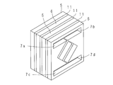
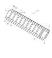
- FIG. 1 is a perspective view showing the configuration of the mover according to the first embodiment of the present invention.
- the mover 1 includes four types of flat-plate magnets 3a, 3b, 3c, and 3d in this order on the outer surface of an inner yoke 2 made of a rectangular cylindrical soft magnetic material in the axial direction of the inner yoke 2 (of the mover 1).
- white arrows indicate the magnetization directions of the respective flat magnets 3a, 3b, 3c, and 3d.
- the flat magnet (first flat magnet) 3a is a flat permanent magnet that is perpendicular to the outer surface of the inner yoke 2 and is magnetized in the direction from the inner side toward the outer side.
- the flat magnet (second flat magnet) 3c is a flat permanent magnet that is perpendicular to the outer surface of the inner yoke 2 and is magnetized in the direction from the outer side to the inner side. Therefore, the magnetization directions of the flat magnet 3 a and the flat magnet 3 c are perpendicular to the outer surface of the inner yoke 2 and are opposite to each other.
- the flat magnets 3b and 3d are flat permanent magnets magnetized in the axial direction of the inner yoke 2 (longitudinal direction of the outer surface) and from the adjacent flat magnet 3c toward the adjacent flat magnet 3a. It is. Therefore, the magnetization directions of the flat magnet 3b and the flat magnet 3d are the axial directions of the inner yoke 2 and opposite to each other.
- the installation position of these flat magnets 3a, 3b, 3c, 3d between the outer surfaces of the inner yoke 2 is 1 / of the total length of the four types of flat magnets 3a, 3b, 3c, 3d. It is displaced by a dimension of 4 or less.
- the installation positions of these flat magnets 3a, 3b, 3c, and 3d between the two opposing outer surfaces are the same on the four outer surfaces of the square cylindrical inner yoke 2.
- the installation positions of these flat magnets 3a, 3b, 3c, 3d between two adjacent outer surfaces are deviated by the length of the flat magnet 3b or 3d.
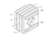
- FIGS. 2A to 2C and 3A and 3B are perspective views showing the configuration of the armature used in the linear motor according to the present invention, in which FIGS. 2A to 3C and 3A are partial configuration diagrams, and FIG. It is a block diagram.
- the armature 4 is a first monopolar unit in which the square plate-like first monopolar units 5 shown in FIG. 2A and the square plate-like second monopolar units 6 shown in FIG. A frame-shaped spacer unit 11 as shown in FIG. 2C is inserted between the fifth and second single-pole units 6 (see FIG. 3A).
- the first single pole unit 5 is formed of a soft magnetic material, and has a square opening 5a through which the mover 1 passes, and a yoke 5b as a frame disposed outside the opening 5a. And a core portion 5c extending from the yoke portion 5b toward the opening portion 5a.
- the direction of the side of the square plate-shaped first single-pole unit 5 and the direction of the side of the opening 5a form an angle of 45 degrees.
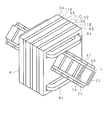
- the second single-pole unit 6 is made of a soft magnetic material, and has a square opening 6a through which the mover 1 passes, and a yoke part as a frame disposed outside the opening 6a. 6b and a core portion 6c extending from the yoke portion 6b toward the opening 6a.
- the direction of the side of the square plate-like second single-pole unit 6 and the direction of the side of the opening 6a form an angle of 45 degrees.
- the second single-pole unit 6 is configured by rotating the first single-pole unit 5 by 90 degrees
- the yoke portion 5b and the yoke portion 6b are in contact with each other, but the core portion 5c and the core portion 6c are in contact with each other. However, there is a gap between them to avoid a magnetic short circuit.
- the core portion 5c in the first single-pole unit 5 (the upper core portion 5c in FIG. 2A) is collectively collected.
- the winding wire 8a is wound, and the other core portion 5c (see FIG. 2A) in the first monopolar unit 5 passes through the common gap portions 7c and 7d of the first monopolar unit 5 and the second monopolar unit 6.
- Winding wire 8b is collectively wound around the lower core portion 5c). Then, the two wires 8a and 8b are connected so that the energization directions of the wire 8a and the wire 8b are reversed (see FIG. 3B).
- FIG. 4 is a perspective view showing the configuration of the linear motor 10 according to the present invention
- FIG. 5 is a partially broken perspective view showing the configuration of the linear motor 10.
- the armature 4 functions as a stator. Then, by applying a current in the reverse direction to the winding wires 8a and 8b, the mover 1 penetrating through the hollow portion 9 of the armature 4 performs a reciprocating linear motion with respect to the armature 4 (stator).
- FIG. 6 is a cross-sectional view showing the energized state and magnetomotive force in the armature 4.
- ⁇ flow from the back of the paper to the front
- ⁇ flow from the front to the back of the paper
- the white arrow indicates the direction of the magnetomotive force applied to the core portions 5c and 6c by energization of the coil.
- each single-pole unit has a uniform thickness by inserting the spacer unit 11 composed of only a frame-shaped yoke between adjacent single-pole units, The core parts of the unit are prevented from contacting each other.
- there is no need to make the core part thinner than the yoke part in each single pole unit no extra processing is required, and a single pole unit having a uniform thickness as a whole. Since it can be used, the manufacturing process can be simplified.
- each single-pole unit when the thickness of the core part is made thinner than the thickness of the yoke part and the two single-pole units are overlapped, the core parts of both single-pole units do not contact each other. It may be configured. In this example, the spacer unit 11 as described above is unnecessary.
- mover 1 is made into the square shape (square in the said example), a magnet can be divided
- the installation positions of the flat magnets 3a, 3b, 3c, 3d between the adjacent outer surfaces of the inner yoke 2 of the mover 1 are deviated in the axial direction of the inner yoke 2 (moving direction of the mover 1). . Therefore, the effect can be improved in reducing thrust ripple and / or detent force, and the mover 1 can realize smooth linear movement by eliminating cogging.
- the directions of the sides of the openings 5a and 6a of the single-pole units 5 and 6 are inclined by 45 degrees with respect to the directions of the sides of the main bodies of the first single-pole unit 5 and the second single-pole unit 6. Therefore, the flow of magnetic flux in the armature 4 becomes smooth and magnetic saturation hardly occurs.
- a total of 20 plate-like magnets 3a, 3b, 3c, and 3d are sequentially connected to each outer surface of the inner yoke 2, but this is only an example.
- the number may be any number.
- two sets of the first single pole unit 5 and the second single pole unit 6 are alternately arranged, this is an example, and the number of sets may be any number.
- the shape of the inner yoke 2 is a quadrangular cylinder, but this is an example, and may be another polygonal cylinder such as an octagonal cylinder.
- the winding lines 8a and 8b are collectively applied to the core portion 5c of the first single pole unit 5, but the core portions 6c of the second single pole unit 6 are collectively bundled. You may make it give a line.
- the installation positions of the flat magnets 3a, 3b, 3c, 3d on the two opposite outer surfaces are the same on the four outer surfaces of the square cylindrical inner yoke 2, and two adjacent two
- the installation positions of the flat magnets 3a, 3b, 3c, 3d between the outer side surfaces are deviated, the installation positions of the flat magnets 3a, 3b, 3c, 3d between the four outer surfaces of the inner yoke 2 are configured. It may be configured so that all are different by slightly deviating. However, even in such a configuration example, the maximum deviation amount is set to 1 ⁇ 4 or less of the length of a set of four flat magnets 3a, 3b, 3c, and 3d.
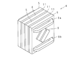
- FIG. 7 is perspective views showing configurations of the mover 21, the armature 4, and the linear motor 30 according to the second embodiment, respectively.
- FIGS. 7, 8A-C, and 9 are perspective views showing configurations of the mover 21, the armature 4, and the linear motor 30 according to the second embodiment, respectively.
- FIGS. 7, 8A-C, and 9 the same parts as those in FIGS. 1, 2A-C, 3A, and B are denoted by the same reference numerals, and description thereof is omitted.
- linear guide rails 12 are provided extending in the axial direction at two corners of the outer surface of the inner yoke 2. Further, notches for passing the linear guide rails 12 may be provided in the openings of the first single-pole unit 5 and the second single-pole unit 6 constituting the armature 4.
- the armature 4 of the single-phase unit is provided by providing the mover support frame 14 shown in FIG. 8B provided with the linear guide slider 13 on the front and back surfaces of the main body shown in FIG. Configure (see FIG. 8C). Then, the mover 1 shown in FIG. 7 is passed through the armature 4 shown in FIG. 8C to form a single-phase drive linear motor (unit for single phase) 30 (see FIG. 9).
- the linear guide rail 12 supports the mover 21 by pressing it from the lateral direction. Therefore, the rigidity can be further increased. Further, the linear guide rail 12 can suppress vibrations such as flexural vibration and resonance vibration. Therefore, even if it is moved at a high speed, a large vibration does not occur, and a stable high-speed linear movement without rattling can be realized.
- FIG. 10 is a perspective view showing the configuration of the mover according to the third embodiment.
- the mover 31 according to the third embodiment is configured by excluding the plate-like magnets 3b and 3d magnetized in the axial direction of the mover from the mover 1 (see FIG. 1) according to the first embodiment. ing. That is, the mover 31 has two types of flat magnets 3a and 3c arranged in this order on the outer surface of the inner yoke 2 made of a rectangular cylindrical soft magnetic body in the axial direction of the inner yoke 2 (the moving direction of the mover 31). ) Are alternately installed.
- FIG. 10 is a perspective view showing the configuration of the mover according to the third embodiment.
- the mover 31 according to the third embodiment is configured by excluding the plate-like magnets 3b and 3d magnetized in the axial direction of the mover from the mover 1 (see FIG. 1) according to the first embodiment. ing. That is, the mover 31 has two types of flat magnets 3a and 3c arranged
- the flat magnet (first flat magnet) 3a is a flat permanent magnet that is perpendicular to the outer surface of the inner yoke 2 and is magnetized in the direction from the inner side toward the outer side.
- the flat magnet (second flat magnet) 3c is a flat permanent magnet that is perpendicular to the outer surface of the inner yoke 2 and is magnetized in the direction from the outer side to the inner side. Therefore, the magnetization directions of the flat magnet 3 a and the flat magnet 3 c are perpendicular to the outer surface of the inner yoke 2 and are opposite to each other.
- the installation position of these flat magnets 3a and 3c between the outer surfaces of the inner yoke 2 is deviated by a dimension of 1/4 or less of the total length of the two types of flat magnets 3a and 3c. ing.
- the installation positions of these flat magnets 3a and 3c are the same between the two outer surfaces facing each other on the four outer surfaces of the square cylindrical inner yoke 2, but two adjacent surfaces are adjacent to each other.
- the installation positions of these flat magnets 3a, 3c between the two outer surfaces are deviated.
- the configuration of the armature according to the third embodiment is the same as the configuration of the armature 4 according to the above-described first embodiment (see FIGS. 2A to 2C and FIGS. 3A and B).
- the armature 4 functions as a stator and is passed through the hollow portion 9 of the armature 4 by flowing a current in the reverse direction to the winding wires 8a and 8b.
- the movable element 31 reciprocates linearly with respect to the armature 4 (stator).
- the installation positions of the flat magnets 3a and 3c between the adjacent outer surfaces of the inner yoke 2 of the mover 31 are deviated in the axial direction of the inner yoke 2 (moving direction of the mover 31). Therefore, it is possible to improve the effect of reducing the thrust ripple and / or the detent force, the cogging is eliminated, and the smooth linear movement of the mover 31 is realized.
- the structure which connected the total of ten flat magnets 3a and 3c in order of 5 sets each this is an example and the number may be arbitrary numbers.
- the shape of the inner yoke 2 is a rectangular cylinder, this is an example, and may be another polygonal cylinder such as an octagonal cylinder.
- the installation positions of the flat magnets 3a and 3c on the two outer surfaces facing each other are the same, and the flat magnets 3a and 3c between the two outer surfaces adjacent to each other are the same.
- the installation position is deviated, the installation positions of the flat magnets 3a and 3c between the four outer surfaces of the inner yoke 2 may be slightly deviated so that they are all different.
- the maximum deviation amount is set to 1 ⁇ 4 or less of the length of a set of two flat magnets 3a and 3c.
- two-phase driving is performed by one core unit.
- three-phase driving is used, so that three armatures are arranged in a straight line and the mover is passed through them. Therefore, there is a drawback that the total length of the constructed linear motor is long.
- two-phase driving is performed by a single core unit, and the overall length, which is a problem of the three-phase separation independent type, is greatly improved. .
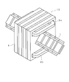
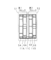
- FIG. 11 is a perspective view showing the configuration of the mover according to the fourth embodiment of the present invention.
- the mover 41 includes four types of flat-plate magnets 3a, 3b, 3c, 3d in this order on the four outer side surfaces 2a, 2b, 2c, 2d of the inner yoke 2 made of a rectangular cylindrical soft magnetic material. It is configured to be alternately installed in two axial directions (moving direction of the mover 41). In FIG. 11, white arrows indicate the magnetization directions of the respective plate magnets 3a, 3b, 3c, 3d.
- the flat magnet (first flat magnet) 3a is a flat permanent magnet that is perpendicular to the outer surface of the inner yoke 2 and is magnetized in the direction from the inner side toward the outer side.
- the flat magnet (second flat magnet) 3c is a flat permanent magnet that is perpendicular to the outer surface of the inner yoke 2 and is magnetized in the direction from the outer side to the inner side. Therefore, the magnetization directions of the flat magnet 3 a and the flat magnet 3 c are perpendicular to the outer surface of the inner yoke 2 and are opposite to each other.
- the flat magnets 3b and 3d are flat permanent magnets magnetized in the axial direction of the inner yoke 2 (longitudinal direction of the outer surface) and from the adjacent flat magnet 3c toward the adjacent flat magnet 3a. It is. Therefore, the magnetization directions of the flat magnet 3b and the flat magnet 3d are the axial directions of the inner yoke 2 and opposite to each other.
- the installation position of the flat magnets 3a, 3b, 3c, 3d in 2d is a dimension that is a quarter of the total length of the four types of flat magnets 3a, 3b, 3c, 3d (the field period is ⁇ ⁇ / 4, and the electrical angle is 90 degrees).
- the configuration of the armature according to the fourth embodiment is the same as the configuration of the armature 4 according to the first embodiment described above (see FIGS. 2A to 2C and FIGS. 3A and B). Omitted.
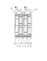
- FIG. 12 is a perspective view showing the configuration of the linear motor 50 according to the fourth embodiment
- FIG. 13 is a partially broken perspective view showing the configuration of the linear motor 50.
- These units are alternately arranged in the order of the first single-pole unit 5A, the spacer unit 11A, the second single-pole unit 6A, the spacer unit 11C, the first single-pole unit 5B, the spacer unit 11B, and the second single-pole unit 6B.
- the armature 4 is configured.
- the above-described mover 41 shown in FIG. 11 is passed through the hollow portion 9 formed by connecting the openings 5a and 6a of the armature 4 (see FIG. 3B), so that 2 according to the fourth embodiment.
- a phase-driven linear motor 50 is configured.
- the outer side surfaces 2a and 2b adjacent to each other on the upper side of the inner yoke 2 in the mover 41 are opposed to the upper core portion 5c (the upper side line 8a as the first side line) in the first single pole unit 5.
- the adjacent outer surfaces 2c and 2d on the lower side of the inner yoke 2 are opposed to the lower core portion 5c (the lower winding line 8b as the second winding line) in the first single-pole unit 5.
- the mover 41 is passed through the hollow portion 9 of the armature 4.
- a sinusoidal current is passed through the winding line 8a and a cosine wave current is passed through the winding line 8b so that the energization phase is 90 degrees different between the winding line 8a and the winding line 8b.
- the armature 4 functions as a stator. By passing currents that are 90 degrees out of phase in the winding wires 8a and 8b, a thrust can be continuously generated in the mover 41 penetrating through the hollow portion 9 of the armature 4, so that the mover 41 is armature. Reciprocating linear motion is performed with respect to 4 (stator). At this time, since the peak of thrust is alternately obtained by the upper core portion 5c and the lower core portion 5c of the armature 4, continuous thrust is obtained by one core unit, and linearity of two-phase driving is obtained.
- the motor 50 can be realized.
- this fourth embodiment also has the same advantages as described above in the first and third embodiments. That is, since the spacer unit 11 is inserted between the adjacent single-pole units, the thickness of the core portion in each single-pole unit does not need to be thinner than the thickness of the yoke portion, and no extra processing is required. Since a single-pole unit having a uniform thickness as a whole can be used, the manufacturing process can be simplified.
- the inner yoke is large, and the mass of the mover becomes heavy, and high-speed response is difficult.
- the inner yoke 2 is hollow. Moreover, since the magnetic flux generated inside can be reduced and the thickness of the rectangular inner yoke 2 can be reduced, the weight of the mover 41 can be reduced. Therefore, the response speed of the mover 41 can be increased.
- the armature 4 according to the fourth embodiment is provided with the winding wires 8a and 8b all together without applying the winding wires for each pole, so even if the magnetic pole pitch is small Since the wire structure is simple without being complicated, it is easy to reduce the size.
- the cross-sectional shape of the mover 41 is a quadrangle
- the magnet can be divided into four surfaces and a flat magnet can be used. Therefore, compared to a cylindrical linear motor, the degree of freedom of manufacture including selection of the magnet to be used is extremely high, and the mover 41 having excellent rigidity can be easily manufactured.
- the directions of the sides of the openings 5a and 6a of the single-pole units 5 and 6 are inclined by 45 degrees with respect to the directions of the sides of the main bodies of the first single-pole unit 5 and the second single-pole unit 6. Therefore, the flow of magnetic flux in the armature 4 becomes smooth and magnetic saturation hardly occurs.
- a sinusoidal current is passed through the winding line 8a and a cosine wave current is passed through the winding line 8b, but this is an example, and the winding line 8a and the winding line 8b are 90 degrees out of phase different in electrical angle.
- a current may be passed.
- the current waveform applied to the winding line 8a and the winding line 8b may be a rectangular wave shape or a trapezoidal wave shape having a 90 ° phase difference in electrical angle.
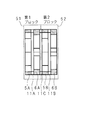
- FIG. 14 is a cross-sectional view of a standard armature 4.
- the armature 4 is configured by being alternately arranged and integrated in the order of 6B.
- the three spacer units 11A, 11B, and 11C have the same thickness, and the first single-pole unit 5A, the second single-pole unit 6A, the first single-pole unit 5B, and the second single-pole unit. 6B are equally arranged.
- a set of the first single pole unit 5A, the spacer unit 11A, and the second single pole unit 6A is referred to as a first block 51, and a set of the first single pole unit 5B, the spacer unit 11B, and the second single pole unit 6B. Is referred to as a second block 52.
- FIG. 15 is a cross-sectional view of the armature 4 for explaining a method for reducing the second-order and sixth-order harmonic components.
- the electrical angle is expanded by 90 degrees from the uniform arrangement of the single-pole units as shown in FIG. That is, when the distance between the first block 51 and the second block 52 (the distance between the second single-pole unit 6A and the first single-pole unit 5B) is an electrical angle of 90 degrees (the field period is ⁇ ), the length ⁇ / 4) and widened between the first single-pole unit 5A and the second single-pole unit 6A and between the first single-pole unit 5B and the second single-pole unit 6B.
- Such a configuration can be easily achieved by increasing the thickness of the spacer unit 11C (by using a thicker spacer unit 11C) as compared to the example shown in FIG.
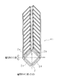
- FIG. 16 is a perspective view of the mover 41 for explaining a technique for reducing the fourth-order harmonic component.
- the flat magnets 3a, 3b, 3c, 3d are deviated from the installation positions of the flat magnets 3a, 3b, 3c, 3d by an electrical angle of 45 degrees (length ⁇ / 8), and the flat magnets 3a, 3b, 3c, 3d on the lower outer surface 2c are displaced. Similarly to the installation position, the installation position of the flat magnets 3a, 3b, 3c, 3d on the lower outer surface 2d is deviated by an electrical angle of 45 degrees (length ⁇ / 8).
- FIG. 17 is a cross-sectional view of the armature 4 for explaining a technique for reducing the eighth-order harmonic component.
- the first single pole unit 5A and the second single pole without changing the positions of the center of gravity of the first block 51 and the second block 52 after adjusting the thickness of the spacer unit 11C as shown in FIG.
- the space between the units 6A and between the first single-pole unit 5B and the second single-pole unit 6B is increased by an electrical angle of 22.5 degrees (length ⁇ / 16), respectively (see white arrows). .
- Such a configuration can be easily achieved by increasing the thickness of the spacer units 11A and 11B (by using thicker spacer units 11A and 11B).
- first reduction method is merely an example, and the method of reducing each harmonic component of thrust ripple and detent force is not limited to this, and other methods may be used. Another method for reducing each harmonic component will be described below.
- the second and sixth harmonic components of thrust ripple and detent force are reduced by adjusting the magnet arrangement of the mover, and the fourth harmonic component is used to adjust the spacing between both blocks of the armature.
- the eighth harmonic component is reduced by adjusting the distance between the first single pole unit and the second single pole unit in each block.
- the second and sixth harmonic components of thrust ripple and detent force are reduced by adjusting the spacing between both blocks of the armature, and the fourth harmonic component is the first single pole in each block. It is reduced by adjusting the distance between the unit and the second single-pole unit, and the eighth-order harmonic component is reduced by adjusting the magnet arrangement of the mover.
- the flat magnets 3b and 3d magnetized in the axial direction of the mover may not be provided.
- the mover has two types of flat magnets 3a and 3c in this order in the axial direction of the inner yoke 2 (movement of the mover) on each outer side surface 2a-2d of the inner yoke 2 made of a rectangular cylindrical soft magnetic material.
- the installation positions of the flat magnets 3a and 3c are 1/4 dimension of the length of the two types of flat magnets 3a and 3c ( ⁇ / 4 when the field period is ⁇ , 90 in electrical angle) Degree).
- the outer surface 2a on the upper side of the inner yoke 2 is reduced in the same manner as in the fourth embodiment described above. While maintaining the state where the electrical angle between the installation position of the flat magnets 3a and 3c in 2b and the installation position of the flat magnets 3a and 3c in the lower outer surfaces 2c and 2d is shifted by 90 degrees, the upper side The installation position of the flat magnets 3a and 3c on the upper outer surface 2b as well as the installation position of the flat magnets 3a and 3c on the outer side surface 2a is a predetermined electrical angle (90 degrees and 4th order for the second and sixth orders).
- the installation position of Electrical angle component (secondary and 90 degrees for the 6 th, 45 degrees for 4-order, 22.5 degrees for 8-order) is offset.
- the linear guide rail 12 (see FIG. 5) is extended to two corners of the outer surface of the inner yoke 2 in the mover 41. 7), and further, a notch for passing the linear guide rail 12 may be provided in the opening of the first single-pole unit 5 and the second single-pole unit 6 constituting the armature 4.
- a mover 1 used for a linear motor a mover including a square cylindrical inner yoke and a flat permanent magnet as shown in FIG. 1 was produced.
- the inner yoke 2 to be used is a square tube made of pure iron, the outer shape is 22 mm square, and the inner shape is 18 mm square.
- the flat magnet 3a is a permanent magnet having a length of 10 mm, a width of 22 mm, and a height of 4 mm, and is magnetized in the height direction from the inner side (moving direction axis center) to the outer side of the mover 1.
- the magnetization directions of the flat magnet 3a and the flat magnet 3c are in the height direction (the direction perpendicular to the outer surface of the inner yoke 2), but the directions are opposite to each other (the white arrow in FIG. 1). reference).
- the flat magnet 3b is a permanent magnet having a length of 2 mm, a width of 22 mm, and a height of 4 mm, and is magnetized in the length direction from the flat magnet 3c of the mover 1 toward the flat magnet 3a.
- the magnetization directions of the flat magnet 3b and the flat magnet 3d are in the length direction (moving direction of the mover 1), but the directions are opposite to each other (see white arrows in FIG. 1).
- the installation positions of these flat magnets 3a, 3b, 3c, 3d are shifted by the length (2 mm) of the flat magnet 3b or 3d between the outer surfaces of the adjacent inner yokes 2.
- an armature 4 was produced. Sixteen pieces of armature material having a shape as shown in FIG. 18A are cut out from a 0.5 mm-thick silicon steel plate, and the sixteen pieces thus cut out are stacked and bonded together to form a first single-pole unit 5 having a thickness of 8 mm, 1 single pole unit 6 was produced (refer to Drawing 2A and B). Further, eight armature materials having a shape as shown in FIG. 18B were cut out from a 0.5 mm-thick silicon steel plate, and these eight cut-out pieces were stacked and bonded to produce a spacer unit 11 having a thickness of 4 mm. (See FIG. 2C).
- Each unit produced in this way is divided into the first single-pole unit 5, the spacer unit 11, the second single-pole unit 6, the spacer unit 11, the first single-pole unit 5, the spacer unit 11, and the second single-pole unit 6.
- a unit for a single phase was constructed by superimposing in order (see FIG. 3A).
- a polyimide tape is spread on the gaps at the four corners where the winding lines for the armature core are to be secured, and on that Lead wires were struck 100 times in two places (see FIG. 3B). And it connected in series so that the direction of the current would be reversed when energized.
- the mover 1 was inserted (see FIG. 4) and fixed to the test bench so that the mover 1 could move in the longitudinal direction without contacting the armature 4.
- One end of a pair of drive coils wound on three armatures 4 was connected, and the other end was connected to a motor controller using a star connection that connected three-phase power supplies U, V, and W phases. Further, an optical linear scale was bonded to the tip of the mover 1 and a linear encoder was attached to the test bench fixed side so that the position of the mover 1 was read. The position signal detected by the linear encoder is output to the motor controller to control the position of the mover 1.
- the horizontal axis in FIG. 19 is the effective value of the drive current per one armature phase ⁇ the number of coil turns.
- the maximum thrust exceeding 700 N is obtained. Since the mass of the mover 1 was 1.1 kg, the thrust / mover mass ratio was 637 N / kg.
- the mass of the mover In the conventional linear motor (Japanese Patent Laid-Open No. 2002-359962) in another system that can obtain a thrust of 700 N, the mass of the mover is required to be 3 kg or more, so the thrust / mover mass ratio is 233 N / kg or less. is there.
- the mass of the mover can be reduced to about 1/3 in order to obtain the same thrust as compared with the conventional linear motor.
- the present invention can provide a linear motor that is very effective for high-speed processing in a processing machine or the like.
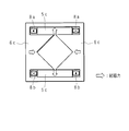
- 20A, 20B, and 20C are a top view, a side view, and a cross-sectional view, respectively, showing a state in which the armature 41 is passed through the armature 4.
- FIG. 1 the linear guide rail 12, the linear guide slider 13, and the mover support frame 14 described in the second embodiment are provided.
- a mover including a square cylindrical inner yoke and a flat permanent magnet as shown in FIG. 11 was produced.
- the inner yoke 2 to be used is a square tube made of pure iron, the outer shape is 32 mm square, and the inner shape is 26 mm square.
- Each of the four outer surfaces 2a-2d of the inner yoke 2 has a set of four types of flat magnets 3a, 3b, 3c, 3d in the axial direction of the inner yoke 2 (moving direction of the mover 1). They were bonded together.
- the flat magnet 3a is a permanent magnet having a length of 10 mm, a width of 25 mm, and a height of 4 mm, and is magnetized in the height direction from the inner side (moving direction axis center) to the outer side of the mover 41.
- the permanent magnet is 10 mm long, 25 mm wide and 4 mm high and is magnetized in the height direction from the outside to the inside of the mover 41.
- the magnetization directions of the flat magnet 3a and the flat magnet 3c are in the height direction (the direction perpendicular to the outer surface of the inner yoke 2), but the directions are opposite to each other (the white arrow in FIG. 11). reference).
- the flat magnet 3b is a permanent magnet having a length of 2 mm, a width of 25 mm, and a height of 4 mm, and is magnetized in the length direction from the flat magnet 3c of the mover 41 toward the flat magnet 3a.
- the magnetization directions of the flat magnet 3b and the flat magnet 3d are in the length direction (moving direction of the mover 41), but the directions are opposite to each other (see white arrows in FIG. 11).
- the installation positions of the magnets 3a, 3b, 3c, and 3d are deviated by 6 mm in the moving direction (axial direction) of the mover 41.
- the total length of the four types of flat magnets 3a, 3b, 3c, 3d is 24 mm, and the deviation of 6 mm is 1/4 of the magnet arrangement period 24 mm, which is the field period ( ⁇ ). This corresponds to the deviation of the dimension ( ⁇ / 4: electrical angle of 90 degrees).
- the installation positions of the flat magnets 3a, 3b, 3c, 3d on the upper outer surface 2a and the installation positions of the flat magnets 3a, 3b, 3c, 3d on the upper outer surface 2b are the same as those of the mover 41.
- the position of the flat magnets 3a, 3b, 3c, 3d on the lower outer surface 2c and the flat magnets 3a, 3b, 3c, similarly on the lower outer surface 2d are shifted by 3 mm in the moving direction.
- the installation position of 3d is deviated by 3 mm in the moving direction of the mover 41.
- This deviation of 3 mm corresponds to the deviation of the electrical angle of 45 degrees (dimension ⁇ / 8 of 1/8 of the field period ( ⁇ ) of 24 mm) described with reference to FIG.
- the movable element 41 having a length of 141 mm, a width of 25 mm, and a height of 4 mm was produced.
- an armature 4 was produced.
- An armature material having a shape as shown in FIG. 21A is cut out from a 0.5 mm-thick silicon steel plate, and these 20 cut-out pieces are stacked and bonded together to form a first single-pole unit 5 (5A, 5B) having a thickness of 10 mm. ),
- the first single-pole unit 6 (6A, 6B) was produced.
- an armature material having a shape as shown in FIG. 21B is cut out from a silicon steel plate having a thickness of 0.5 mm, and the seven pieces that are cut out are stacked and bonded together to form two spacer units 11 (spacers having a thickness of 3.5 mm).
- the units 11A and 11B) were manufactured, and the 13 pieces cut out were stacked and bonded to each other to prepare one spacer unit 11 (spacer unit 11C) having a thickness of 6.5 mm.
- Each unit produced in this way is divided into the first single-pole unit 5A, the spacer unit 11A, the second single-pole unit 6A, the spacer unit 11C, the first single-pole unit 5B, the spacer unit 11B, and the second single-pole unit 6B.
- a core unit having a length of 80 mm, a width of 80 mm, and a height of 53.5 mm ( 10 mm ⁇ 4 + 3.5 mm ⁇ 2 + 6.5 mm ⁇ 1) was formed by superposing them in order.
- the thickness of each of the spacer units 11A, 11B, and 11C has been described with reference to FIGS. 15 and 17 in order to reduce the second, sixth, and eighth harmonic components of thrust ripple and detent force. It is set as appropriate in order to adjust the interval between the magnetic pole teeth.
- FIG. 22 shows a cross-sectional view of the core unit by this first reduction method.
- the thickness of the basic spacer unit is set to 2 mm
- the thickness of the spacer units 11A and 11B is set to 3.5 mm
- the thickness of the spacer unit 11C is set to 6.5 mm.
- a winding tape 8a and a winding wire 8b of the drive coil are coated with polyimide tape in the gap portions at the four corners in the portions where the armature core winding wires are to be provided for insulation, and 2 conductors are placed thereon. I hit the spot 100 times.
- a driving current having a sine waveform and a driving current having a cosine waveform are applied to the winding line 8a and the winding line 8b, respectively.
- a thrust of about 160 N is obtained in a range where the thrust and the drive current are proportional, and a maximum thrust of 200 N or more is obtained.
- such excellent characteristics are achieved with an armature having a total length of only 65 mm.
- the length of the armature having a total length of about 150 mm is necessary, and in the fourth embodiment, the length can be reduced to half or less. Since the linear motor according to the fourth embodiment can be reduced in size and space as described above, it is an optimum linear motor for use in an overlapping manner like the XYZ triaxial drive stage. .
- the second and sixth harmonic components of thrust ripple and detent force are reduced by adjusting the magnet arrangement of the mover 41, and the fourth harmonic component is reduced in both blocks 51 of the armature 4.
- 52 is adjusted by adjusting the interval between the first and second single-pole units 5A and 5B in the block 51 and the first single-pole unit 6A in the block 52. , It is reduced by adjusting the interval between the second single-pole units 6B.
- the installation positions of the flat magnets 3a, 3b, 3c, 3d on the adjacent outer surfaces 2a, 2b on the upper side of the inner yoke 2, and the flat magnets 3a, 3b on the adjacent outer surfaces 2c, 2d on the lower side of the inner yoke 2 , 3c, and 3d are displaced by 6 mm ( ⁇ / 4: electrical angle of 90 degrees) in the moving direction (axial direction) of the mover 41, and a flat magnet on the upper outer surface 2a
- the installation position of 3a, 3b, 3c, 3d and the installation position of the flat magnets 3a, 3b, 3c, 3d on the upper outer surface 2b are 6 mm ( ⁇ / 4: electrical angle) in the moving direction of the mover 41.
- FIG. 24 shows a cross-sectional view of the core unit by the second reduction method.
- ⁇ / 8 electric angle 45
- the distance between the first single-pole unit 5A, 6A and the second single-pole unit 5B, 6B in each of the blocks 51, 52 in order to reduce the eighth-order harmonic component by 3 mm corresponding to the degree) (Magnetic tooth spacing) is increased by 1.5 mm corresponding to ⁇ / 16 (electrical angle 22.5 degrees).
- the interval between the magnetic pole teeth is uniformly increased by 1.5 mm.
- the thickness of each of the spacer units 11A, 11B, and 11C is 3.5 mm
- the second and sixth harmonic components of thrust ripple and detent force are reduced by adjusting the distance between the blocks 51 and 52 of the armature 4, and the fourth harmonic component is reduced in the block 51. Reduced by adjusting the distance between the first single-pole unit 5A and the second single-pole unit 5B and the distance between the first single-pole unit 6A and the second single-pole unit 6B in the block 52, and the eighth harmonic component Is reduced by adjusting the magnet arrangement of the mover 41.
- FIG. 25 shows a cross-sectional view of the core unit by the third reduction method.
- the interval between the magnetic pole teeth is uniformly increased by 3 mm.
- the thickness of each spacer unit 11A, 11B, 11C is 5 mm
- the installation positions of the flat magnets 3a, 3b, 3c, 3d on the adjacent outer surfaces 2a, 2b on the upper side of the inner yoke 2 and the flat magnets 3a on the adjacent outer surfaces 2c, 2d on the lower side of the inner yoke 2 are set.
- 3b, 3c, and 3d are displaced by 6 mm ( ⁇ / 4: electrical angle of 90 degrees) in the moving direction (axial direction) of the mover 41, and a flat plate on the upper outer surface 2a.
- the installation position of the magnets 3a, 3b, 3c, 3d and the installation position of the flat magnets 3a, 3b, 3c, 3d on the upper outer surface 2b are 1.5 mm ( ⁇ / 16: electrical angle 22.5 degrees), and the installation positions of the flat magnets 3a, 3b, 3c, 3d on the lower outer surface 2c, and the flat magnets 3a, 3a on the lower outer surface 2d, 3b, 3c, 3d installation positions Is displaced by 1.5 mm ( ⁇ / 16: electrical angle 22.5 degrees) in the moving direction of the mover 41.
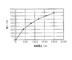
- Example according to the fifth embodiment Two armature drive coils manufactured in the same manner as in the above-described fourth embodiment are connected to a two-phase drive motor controller, and a position sensor is attached to the tip of the mover to provide a two-phase drive motor. A position signal was input to the controller, and the thrust characteristics of the linear motor were measured. The measurement results are shown in FIG.
- the horizontal axis of FIG. 26 is the effective value of the drive current ⁇ the number of turns of the coil.
- a thrust of about 140 N is obtained in a range where the thrust and the drive current are proportional.
- the numerical value of this thrust is a little lower than the example according to the fourth embodiment (about 160 N) because the flat magnet magnetized in the axial direction of the mover is not provided.
- the length can be shortened, and the size and the space can be reduced.
Landscapes
- Engineering & Computer Science (AREA)
- Power Engineering (AREA)
- Physics & Mathematics (AREA)
- Chemical & Material Sciences (AREA)
- Combustion & Propulsion (AREA)
- Electromagnetism (AREA)
- Linear Motors (AREA)
Abstract
Description
図1は、本発明の第1実施の形態に係る可動子の構成を示す斜視図である。可動子1は、四角筒状の軟質磁性体製のインナーヨーク2の各外側面に、4種類の平板状磁石3a,3b,3c,3dをこの順にインナーヨーク2の軸方向(可動子1の移動方向)に交互に設置させた構成をなしている。図1において、白抜矢符は各平板状磁石3a,3b,3c,3dの磁化方向を示している。平板状磁石(第1平板状磁石)3aは、インナーヨーク2の外側面に垂直であって内側から外側に向かう方向に磁化した平板状の永久磁石である。一方、平板状磁石(第2平板状磁石)3cは、インナーヨーク2の外側面に垂直であって外側から内側に向かう方向に磁化した平板状の永久磁石である。よって、平板状磁石3aと平板状磁石3cとの磁化方向は、インナーヨーク2の外側面に垂直な方向であって逆向きになる。
図7、図8A-C、図9はそれぞれ、第2実施の形態に係る可動子21,電機子4,リニアモータ30の構成を示す斜視図である。これらの図7、図8A-C、図9において、図1、図2A-C、図3A,Bと同一部分には同一番号を付して、それらの説明を省略する。
第3実施の形態は、上述した第1実施の形態の変形例である。図10は、第3実施の形態に係る可動子の構成を示す斜視図である。この第3実施の形態に係る可動子31は、第1実施の形態に係る可動子1(図1参照)から可動子の軸方向に磁化された平板状磁石3b,3dを除いた構成をなしている。即ち、可動子31は、四角筒状の軟質磁性体製のインナーヨーク2の各外側面に、2種類の平板状磁石3a,3cをこの順にインナーヨーク2の軸方向(可動子31の移動方向)に交互に設置させた構成をなしている。図10において、白抜矢符は各平板状磁石3a,3cの磁化方向を示している。平板状磁石(第1平板状磁石)3aは、インナーヨーク2の外側面に垂直であって内側から外側に向かう方向に磁化した平板状の永久磁石である。一方、平板状磁石(第2平板状磁石)3cは、インナーヨーク2の外側面に垂直であって外側から内側に向かう方向に磁化した平板状の永久磁石である。よって、平板状磁石3aと平板状磁石3cとの磁化方向は、インナーヨーク2の外側面に垂直な方向であって逆向きになる。
第4実施の形態は、2相駆動を一つのコアユニットで行うようにしたものである。上述した第1または第3実施の形態では3相駆動であるため、3個の電機子を直線状に配置して、それらに可動子を貫通させるようにした構成となっている。したがって、構成されるリニアモータの全長が長いという難点がある。以下に説明する第4実施の形態は、2相駆動を一つのコアユニットで行うように構成して、3相分離独立型の問題点であった全長が長いことを大幅に改良したものである。
図14は、標準的な電機子4の断面図である。上述したように(図12,13参照)、第1単極ユニット5A、スペーサユニット11A、第2単極ユニット6A、スペーサユニット11C、第1単極ユニット5B、スペーサユニット11B、第2単極ユニット6Bの順に交互に配列して一体化して電機子4は構成されている。図14の例では、3枚のスペーサユニット11A,11B,11Cは同一の厚さであり、第1単極ユニット5A、第2単極ユニット6A、第1単極ユニット5B、第2単極ユニット6Bは均等に配置されている。なお、第1単極ユニット5A、スペーサユニット11A及び第2単極ユニット6Aの一組を第1ブロック51と称し、第1単極ユニット5B、スペーサユニット11B及び第2単極ユニット6Bの一組を第2ブロック52と称する。
図16は、4次の高調波成分を低減するための手法を説明するための可動子41の斜視図である。インナーヨーク2の上側の外側面2a,2bにおける平板状磁石3a,3b,3c,3dの設置位置と下側の外側面2c,2dにおける平板状磁石3a,3b,3c,3dの設置位置との電気角90度(長さλ/4)分偏位させた状態を維持したままで、上側の外側面2aにおける平板状磁石3a,3b,3c,3dの設置位置と同じく上側の外側面2bにおける平板状磁石3a,3b,3c,3dの設置位置とを電気角45度(長さλ/8)分偏位させると共に、下側の外側面2cにおける平板状磁石3a,3b,3c,3dの設置位置と同じく下側の外側面2dにおける平板状磁石3a,3b,3c,3dの設置位置とを電気角45度(長さλ/8)分偏位させる。
図17は、8次の高調波成分を低減するための手法を説明するための電機子4の断面図である。上述した図15に示したようなスペーサユニット11Cの厚さの調整を行った後の第1ブロック51及び第2ブロック52の重心位置を変えずに、第1単極ユニット5Aと第2単極ユニット6Aとの間、及び第1単極ユニット5Bと第2単極ユニット6Bとの間をそれぞれ電気角22.5度(長さλ/16)分だけ広げている(白抜矢符参照)。このような構成は、スペーサユニット11A,11Bの厚さを厚くすることにより(より厚いスペーサユニット11A,11Bを用いることにより)容易に達成できる。
この手法では、推力リプル、ディテント力の2次及び6次の高調波成分を可動子の磁石配列の調整にて低減させ、4次の高調波成分を電機子の両ブロック間の間隔の調整にて低減させ、8次の高調波成分を各ブロック内における第1単極ユニット、第2単極ユニット間の間隔の調整にて低減させるようにする。
この手法では、推力リプル、ディテント力の2次及び6次の高調波成分を電機子の両ブロック間の間隔の調整にて低減させ、4次の高調波成分を各ブロック内における第1単極ユニット、第2単極ユニット間の間隔の調整にて低減させ、8次の高調波成分を可動子の磁石配列の調整にて低減させるようにする。
第4実施の形態において、第3実施の形態と同様に、可動子の軸方向に磁化された平板状磁石3b,3dを設けない構成としても良い。
まず、リニアモータに用いる可動子1として、図1に示すような四角筒状のインナーヨークと平板状の永久磁石とを含んだ可動子を作製した。使用するインナーヨーク2は、純鉄製の四角筒状であり、その外側形状は22mm角、内側形状は18mm角である。
一つのコアユニットにて2相駆動を行う第4実施の形態の実施例について説明する。図20A、20B、20Cはそれぞれ、可動子41を電機子4に貫通させた状態を示す上面図、側面図、断面図である。この実施例では、第2実施の形態で説明したリニアガイドレール12、リニアガイドスライダ13及び可動子支持フレーム14を備えている。
この第2低減手法では、推力リプル、ディテント力の2次及び6次の高調波成分を可動子41の磁石配列の調整にて低減させ、4次の高調波成分を電機子4の両ブロック51,52間の間隔の調整にて低減させ、8次の高調波成分をブロック51内における第1単極ユニット5A,第2単極ユニット5B間の間隔及びブロック52内における第1単極ユニット6A,第2単極ユニット6B間の間隔の調整にて低減させる。
この手法では、推力リプル、ディテント力の2次及び6次の高調波成分を電機子4の両ブロック51,52間の間隔の調整にて低減させ、4次の高調波成分をブロック51内における第1単極ユニット5A,第2単極ユニット5B間の間隔及びブロック52内における第1単極ユニット6A,第2単極ユニット6B間の間隔の調整にて低減させ、8次の高調波成分を可動子41の磁石配列の調整にて低減させる。
前述した第4実施の形態による実施例と同様に作製した電機子の2個の駆動コイルを2相駆動用モータコントローラに接続し、可動子の先端に位置センサを取り付けて、2相駆動用モータコントローラに位置信号を入力させ、リニアモータの推力特性を測定した。その測定結果を図26に示す。図26の横軸は、駆動電流の実効値×コイルの捲き数である。
2 インナーヨーク
2a,2b,2c,2d 外側面
3a 平板状磁石(インナーヨークの外側面に垂直に内側から外側へ磁化した磁石:第1平板状磁石)
3b 平板状磁石(インナーヨークの軸方向に磁化した磁石)
3c 平板状磁石(インナーヨークの外側面に垂直に外側から内側へ磁化した磁石:第2平板状磁石)
3d 平板状磁石(インナーヨークの軸方向に磁化した磁石)
4 電機子
5,5A,5B 第1単極ユニット
6,6A,6B 第2単極ユニット
5a,6a 開口部
5b,6b ヨーク部
5c,6c コア部
7a,7b,7c,7d 隙間部分
8a,8b 捲き線
9 中空部
10,30,50 リニアモータ
11,11A,11B,11C スペーサユニット
12 リニアガイドレール
13 リニアガイドスライダ
14 可動子支持フレーム
Claims (11)
- 角筒状の軟質磁性体製のインナーヨークの外側面に複数の平板状の永久磁石を設けたリニアモータの可動子において、
前記複数の平板状の永久磁石として、前記インナーヨークの外側面に垂直な方向に磁化した平板状磁石と前記インナーヨークの軸方向に磁化した平板状磁石とを前記インナーヨークのそれぞれの外側面で前記インナーヨークの軸方向に交互に連ねており、前記垂直な方向に磁化した平板状磁石は、前記インナーヨークの内側から外側に向かう向きに磁化した第1平板状磁石と前記インナーヨークの外側から内側に向かう向きに磁化した第2平板状磁石とが前記インナーヨークの軸方向に交互に配されており、前記軸方向に磁化した平板状磁石は、隣り合う前記第2平板状磁石から隣り合う前記第1平板状磁石に向かう向きに磁化しており、前記インナーヨークの外側面間における前記複数の平板状の永久磁石の設置位置が偏位していることを特徴とする可動子。 - 一つの前記第1平板状磁石、一つの前記第2平板状磁石、及び軸方向に磁化した二つの前記平板状磁石の合計の長さの1/4以下の寸法だけ、前記インナーヨークの外側面間における前記複数の平板状の永久磁石の設置位置が軸方向に偏位していることを特徴とする請求項1記載の可動子。
- 四角筒状の軟質磁性体製のインナーヨークの4面の外側面に複数の平板状の永久磁石を設けたリニアモータの可動子において、
前記複数の平板状の永久磁石として、前記インナーヨークの外側面に垂直な方向に磁化した平板状磁石と前記インナーヨークの軸方向に磁化した平板状磁石とを前記インナーヨークのそれぞれの外側面で前記インナーヨークの軸方向に交互に連ねており、前記垂直な方向に磁化した平板状磁石は、前記インナーヨークの内側から外側に向かう向きに磁化した第1平板状磁石と前記インナーヨークの外側から内側に向かう向きに磁化した第2平板状磁石とが前記インナーヨークの軸方向に交互に配されており、前記軸方向に磁化した平板状磁石は、隣り合う前記第2平板状磁石から隣り合う前記第1平板状磁石に向かう向きに磁化しており、前記インナーヨークの隣り合う一方の2面の外側面における前記複数の平板状の永久磁石の設置位置と、前記インナーヨークの隣り合う他方の2面の外側面における前記複数の平板状の永久磁石の設置位置とが、一つの前記第1平板状磁石、一つの前記第2平板状磁石、及び軸方向に磁化した二つの前記平板状磁石の合計の長さの1/4だけ偏位していることを特徴とする可動子。 - 前記インナーヨークの外側面の隅部に、自身を支持するリニアガイドレールを前記インナーヨークの軸方向に延在させて設けてあることを特徴とする請求項1乃至3の何れかに記載の可動子。
- 角筒状の軟質磁性体製のインナーヨークの外側面に複数の平板状の永久磁石として、前記インナーヨークの外側面に垂直な方向に磁化した平板状磁石と前記インナーヨークの軸方向に磁化した平板状磁石とを前記インナーヨークのそれぞれの外側面で前記インナーヨークの軸方向に交互に連ねており、前記垂直な方向に磁化した平板状磁石は、前記インナーヨークの内側から外側に向かう向きに磁化した第1平板状磁石と前記インナーヨークの外側から内側に向かう向きに磁化した第2平板状磁石とが前記インナーヨークの軸方向に交互に配されており、前記軸方向に磁化した平板状磁石は、隣り合う前記第2平板状磁石から隣り合う前記第1平板状磁石に向かう向きに磁化しており、前記インナーヨークの外側面間における前記複数の平板状の永久磁石の設置位置が偏位している可動子を、
角形状の開口部、該開口部の外側に配置したヨーク部、及び該ヨーク部から前記開口部に向かう方向に延設させたコア部を有する軟質磁性体製の第1単極ユニットと、角形状の開口部、該開口部の外側に配置したヨーク部、及び前記第1単極ユニットのコア部を90度回転させた位置に設けられ、該ヨーク部から前記開口部に向かう方向に延設させたコア部を有する軟質磁性体製の第2単極ユニットとを交互に重ねてなり、前記第1単極ユニットの複数のコア部及び/または前記第2単極ユニットの複数のコア部に捲き線を施してある電機子の前記第1単極ユニットの開口部及び前記第2単極ユニットの開口部に貫通させてあることを特徴とするリニアモータ。 - 角筒状の軟質磁性体製のインナーヨークの外側面に複数の平板状の永久磁石として、前記インナーヨークの内側から外側に向かう向きに磁化した第1平板状磁石と前記インナーヨークの外側から内側に向かう向きに磁化した第2平板状磁石とが前記インナーヨークのそれぞれの外側面で前記インナーヨークの軸方向に交互に配されており、前記インナーヨークの外側面間における前記複数の平板状の永久磁石の設置位置が偏位している可動子を、
角形状の開口部、該開口部の外側に配置したヨーク部、及び該ヨーク部から前記開口部に向かう方向に延設させたコア部を有する軟質磁性体製の第1単極ユニットと、角形状の開口部、該開口部の外側に配置したヨーク部、及び前記第1単極ユニットのコア部を90度回転させた位置に設けられ、該ヨーク部から前記開口部に向かう方向に延設させたコア部を有する軟質磁性体製の第2単極ユニットとを交互に重ねてなり、前記第1単極ユニットの複数のコア部及び/または前記第2単極ユニットの複数のコア部に捲き線を施してある電機子の前記第1単極ユニットの開口部及び前記第2単極ユニットの開口部に貫通させてあることを特徴とするリニアモータ。 - 四角筒状の軟質磁性体製のインナーヨークの4面の外側面に複数の平板状の永久磁石として、前記インナーヨークの外側面に垂直な方向に磁化した平板状磁石と前記インナーヨークの軸方向に磁化した平板状磁石とを前記インナーヨークのそれぞれの外側面で前記インナーヨークの軸方向に交互に連ねており、前記垂直な方向に磁化した平板状磁石は、前記インナーヨークの内側から外側に向かう向きに磁化した第1平板状磁石と前記インナーヨークの外側から内側に向かう向きに磁化した第2平板状磁石とが前記インナーヨークの軸方向に交互に配されており、前記軸方向に磁化した平板状磁石は、隣り合う前記第2平板状磁石から隣り合う前記第1平板状磁石に向かう向きに磁化しており、前記インナーヨークの隣り合う一方の2面の外側面における前記複数の平板状の永久磁石の設置位置と、前記インナーヨークの隣り合う他方の2面の外側面における前記複数の平板状の永久磁石の設置位置とが、一つの前記第1平板状磁石、一つの前記第2平板状磁石、及び軸方向に磁化した二つの前記平板状磁石の合計の長さの1/4だけ偏位している可動子を、
角形状の開口部、該開口部の外側に配置したヨーク部、及び該ヨーク部から前記開口部に向かう方向に延設させたコア部を有する軟質磁性体製の第1単極ユニットと、角形状の開口部、該開口部の外側に配置したヨーク部、及び前記第1単極ユニットのコア部を90度回転させた位置に設けられ、該ヨーク部から前記開口部に向かう方向に延設させたコア部を有する軟質磁性体製の第2単極ユニットとを交互に重ねてなり、前記第1単極ユニットの複数のコア部または前記第2単極ユニットの複数のコア部の2箇所に第1の捲き線及び第2の捲き線を施してある電機子の前記第1単極ユニットの開口部及び前記第2単極ユニットの開口部に、前記一方の2面の外側面における前記複数の平板状の永久磁石が前記第1の捲き線に対向し、前記他方の2面の外側面における前記複数の平板状の永久磁石が前記第2の捲き線に対向するように貫通させてあり、
前記第1の捲き線と前記第2の捲き線とに電気角で90度位相が異なる電流を印加すべくなしてあることを特徴とするリニアモータ。 - 前記一方の2面の外側面間同士で前記複数の平板状の永久磁石の設置位置が偏位しており、前記他方の2面の外側面間同士で前記複数の平板状の永久磁石の設置位置が偏位していることを特徴とする請求項7記載のリニアモータ。
- 隣り合う前記第1単極ユニットと前記第2単極ユニットとの間隔を調整してあることを特徴とする請求項7記載のリニアモータ。
- 前記インナーヨークは四角筒状であって、前記開口部は四角形状であり、前記第1単極ユニット及び第2単極ユニットは四角形状であり、前記第1単極ユニット及び第2単極ユニットの辺の方向と前記開口部の辺の方向とが45度の角度をなしていることを特徴とする請求項5乃至9の何れかに記載のリニアモータ。
- 重なり合う前記第1単極ユニットと前記第2単極ユニットとの間に、前記第1単極ユニット及び第2単極ユニットのコア部同士が接触しないように軟質磁性体製のスペーサを挟んでいることを特徴とする請求項5乃至10の何れかに記載のリニアモータ。
Priority Applications (5)
| Application Number | Priority Date | Filing Date | Title |
|---|---|---|---|
| US13/145,938 US8723376B2 (en) | 2009-01-23 | 2010-01-22 | Mover and linear motor |
| JP2010547524A JP5510338B2 (ja) | 2009-01-23 | 2010-01-22 | リニアモータ |
| CN201080005348.XA CN102292900B (zh) | 2009-01-23 | 2010-01-22 | 动子及线性马达 |
| EP10733547.3A EP2390991B1 (en) | 2009-01-23 | 2010-01-22 | Mover and linear motor |
| US14/217,979 US9071124B2 (en) | 2009-01-23 | 2014-03-18 | Mover and linear motor |
Applications Claiming Priority (2)
| Application Number | Priority Date | Filing Date | Title |
|---|---|---|---|
| JP2009013259 | 2009-01-23 | ||
| JP2009-013259 | 2009-01-23 |
Related Child Applications (2)
| Application Number | Title | Priority Date | Filing Date |
|---|---|---|---|
| US13/145,938 A-371-Of-International US8723376B2 (en) | 2009-01-23 | 2010-01-22 | Mover and linear motor |
| US14/217,979 Division US9071124B2 (en) | 2009-01-23 | 2014-03-18 | Mover and linear motor |
Publications (1)
| Publication Number | Publication Date |
|---|---|
| WO2010084940A1 true WO2010084940A1 (ja) | 2010-07-29 |
Family
ID=42355992
Family Applications (1)
| Application Number | Title | Priority Date | Filing Date |
|---|---|---|---|
| PCT/JP2010/050761 Ceased WO2010084940A1 (ja) | 2009-01-23 | 2010-01-22 | 可動子及びリニアモータ |
Country Status (7)
| Country | Link |
|---|---|
| US (2) | US8723376B2 (ja) |
| EP (1) | EP2390991B1 (ja) |
| JP (1) | JP5510338B2 (ja) |
| KR (1) | KR101652842B1 (ja) |
| CN (1) | CN102292900B (ja) |
| TW (1) | TWI460966B (ja) |
| WO (1) | WO2010084940A1 (ja) |
Cited By (2)
| Publication number | Priority date | Publication date | Assignee | Title |
|---|---|---|---|---|
| WO2015146874A1 (ja) * | 2014-03-28 | 2015-10-01 | 日立金属株式会社 | アクチュエータ、可動子及び電機子 |
| JP2017147800A (ja) * | 2016-02-16 | 2017-08-24 | 株式会社日立製作所 | リニアモータおよび遮断装置 |
Families Citing this family (20)
| Publication number | Priority date | Publication date | Assignee | Title |
|---|---|---|---|---|
| TWI500241B (zh) * | 2012-02-16 | 2015-09-11 | Hitachi Metals Ltd | 線性馬達 |
| DE102012204916A1 (de) | 2012-03-27 | 2013-10-02 | Beckhoff Automation Gmbh | Statorvorrichtung für einen Linearmotor und lineares Transportsystem |
| DE102012204917A1 (de) | 2012-03-27 | 2013-10-02 | Beckhoff Automation Gmbh | Positionserfassungsvorrichtung und Verfahren zum Erfassen einer Position eines beweglichen Elements einer Antriebsvorrichtung |
| DE102012204919A1 (de) * | 2012-03-27 | 2013-10-02 | Beckhoff Automation Gmbh | Statorvorrichtung für einen linearmotor und lineares transportsystem |
| TWI487250B (zh) * | 2013-04-08 | 2015-06-01 | Delta Electronics Inc | 軸式線性馬達 |
| CA2831197A1 (en) * | 2013-10-28 | 2015-04-28 | Patrick Mcfadden | Electric linear actuator |
| JP6353771B2 (ja) * | 2014-11-25 | 2018-07-04 | 株式会社日立製作所 | リニアモータ及びリニアモータを搭載した圧縮機 |
| US10651718B2 (en) | 2015-07-20 | 2020-05-12 | Motx Ltd. | Transverse flux linear motor |
| US10811950B2 (en) * | 2015-08-07 | 2020-10-20 | Hitachi, Ltd. | Linear motor and device provided with linear motor |
| CN106961200B (zh) * | 2016-01-11 | 2023-07-18 | 珠海格力节能环保制冷技术研究中心有限公司 | 一种直线电机及压缩机 |
| TWI664795B (zh) * | 2017-03-24 | 2019-07-01 | 日商日立金屬股份有限公司 | Linear motor |
| CN107425629B (zh) * | 2017-05-27 | 2020-01-10 | 南京航空航天大学 | 一种永磁电机转子 |
| JP6885214B2 (ja) * | 2017-06-21 | 2021-06-09 | 株式会社デンソー | モータ制御装置及びモータシステム |
| CN109510428A (zh) * | 2018-10-17 | 2019-03-22 | 南方电机科技有限公司 | 一种线性电机及自动化设备 |
| IL295867B2 (en) * | 2020-02-27 | 2025-07-01 | Motx Ltd | A contactless electrical power transmitter and a driving device with which |
| JP7335854B2 (ja) * | 2020-06-15 | 2023-08-30 | 株式会社神戸製鋼所 | 直動電動機 |
| JP7491138B2 (ja) * | 2020-08-21 | 2024-05-28 | 富士電機株式会社 | 永久磁石界磁、製造方法、リニアモータ |
| JP7540937B2 (ja) * | 2020-12-01 | 2024-08-27 | 株式会社神戸製鋼所 | 磁場発生装置及び電動機 |
| CN114221514B (zh) * | 2021-12-10 | 2024-04-12 | 沈阳工业大学 | 一种多边形永磁直线电动机 |
| CN115051525B (zh) * | 2022-06-30 | 2025-04-04 | 瑞声光电科技(常州)有限公司 | 线性振动马达 |
Citations (5)
| Publication number | Priority date | Publication date | Assignee | Title |
|---|---|---|---|---|
| JP2002142439A (ja) * | 2000-11-06 | 2002-05-17 | Hitachi Ltd | リニアモータとその製造方法 |
| JP2003070226A (ja) * | 2001-08-23 | 2003-03-07 | Shin Etsu Chem Co Ltd | リニア同期モータ |
| JP2003274630A (ja) * | 2002-03-13 | 2003-09-26 | Shin Etsu Chem Co Ltd | リニアモータ |
| JP2005287185A (ja) * | 2004-03-30 | 2005-10-13 | Hitachi Ltd | リニアモータ |
| JP2008228545A (ja) * | 2007-03-16 | 2008-09-25 | Jtekt Corp | 可動磁石型リニアモータ |
Family Cites Families (35)
| Publication number | Priority date | Publication date | Assignee | Title |
|---|---|---|---|---|
| US4760294A (en) | 1982-09-13 | 1988-07-26 | Hansen Thomas C | Linear motor with independently controlled coils |
| US4945268A (en) * | 1987-12-26 | 1990-07-31 | Hitachi, Ltd. | Permanent magnet type linear pulse motor |
| US4945269A (en) * | 1989-01-26 | 1990-07-31 | Science Applications International Corporation | Reciprocating electromagnetic actuator |
| JP3220537B2 (ja) * | 1992-12-21 | 2001-10-22 | オリエンタルモーター株式会社 | リニアパルスモータ |
| JPH08275495A (ja) | 1995-03-31 | 1996-10-18 | Minolta Co Ltd | リニアモータ |
| JP4434383B2 (ja) | 1999-10-20 | 2010-03-17 | 株式会社安川電機 | リニアモータ |
| JP3862927B2 (ja) | 2000-03-31 | 2006-12-27 | 山洋電気株式会社 | シリンダ型リニア同期モータ |
| JP3861593B2 (ja) * | 2000-12-11 | 2006-12-20 | 株式会社日立製作所 | リニアモータ |
| JP2002325421A (ja) * | 2001-02-23 | 2002-11-08 | Canon Inc | リニアモータ、およびこれを用いたステージ装置、露光装置ならびにデバイス製造方法 |
| JP3717436B2 (ja) | 2001-03-30 | 2005-11-16 | 山洋電気株式会社 | シリンダ型リニア同期モータ |
| JP4788986B2 (ja) * | 2001-05-10 | 2011-10-05 | Smc株式会社 | リニアモータ |
| JP4647145B2 (ja) | 2001-07-10 | 2011-03-09 | 山洋電気株式会社 | シリンダ型リニア同期モータ |
| EP1300932B1 (en) * | 2001-10-05 | 2013-12-18 | Canon Kabushiki Kaisha | Linear motor, stage apparatus, and exposure apparatus |
| KR100440389B1 (ko) * | 2001-12-26 | 2004-07-14 | 한국전기연구원 | 2상 횡자속형 영구자석 여자 선형 전동기 |
| JP3616058B2 (ja) * | 2002-01-25 | 2005-02-02 | 山崎 恒彦 | リニアモータ |
| JP3846781B2 (ja) | 2002-02-18 | 2006-11-15 | 株式会社日立製作所 | リニアアクチュエータ |
| JP2004153896A (ja) * | 2002-10-29 | 2004-05-27 | Fuji Electric Fa Components & Systems Co Ltd | リニアアクチュエータ |
| TWM243846U (en) * | 2003-03-26 | 2004-09-11 | C Tek Technology Corp | Stator structure improvement of linear motor |
| KR100518780B1 (ko) * | 2003-07-16 | 2005-10-06 | 학교법인 한양학원 | 선형 엑츄에이터를 위한 가동자 |
| JP4603316B2 (ja) | 2003-08-27 | 2010-12-22 | 山洋電気株式会社 | シリンダ型リニアモータ用可動子 |
| JP4089597B2 (ja) * | 2003-11-18 | 2008-05-28 | 株式会社日立製作所 | リニアモータ及びxyステージ |
| JP4522106B2 (ja) | 2004-02-04 | 2010-08-11 | 山洋電気株式会社 | リニアモータ |
| JP4551684B2 (ja) | 2004-03-31 | 2010-09-29 | 山洋電気株式会社 | シリンダ型リニアモータ |
| JP4264021B2 (ja) | 2004-04-05 | 2009-05-13 | 山洋電気株式会社 | シリンダ形リニア同期モータ |
| JP2006034017A (ja) * | 2004-07-16 | 2006-02-02 | Shin Etsu Chem Co Ltd | 工作機械用リニアモータ |
| KR101181044B1 (ko) * | 2005-10-21 | 2012-09-07 | 가부시키가이샤 야스카와덴키 | 원통형 리니어 모터 |
| JP4925720B2 (ja) | 2006-05-18 | 2012-05-09 | 山洋電気株式会社 | リニアモータ用可動子 |
| JP5194472B2 (ja) * | 2007-02-09 | 2013-05-08 | 株式会社ジェイテクト | リニアモータおよびそれを備えた工具移動装置 |
| JP2008220020A (ja) | 2007-03-02 | 2008-09-18 | Jtekt Corp | 可動磁石型リニアモータ |
| JP5292707B2 (ja) | 2007-03-06 | 2013-09-18 | 株式会社ジェイテクト | 可動磁石型リニアモータ |
| US7830046B2 (en) * | 2007-03-16 | 2010-11-09 | Nikon Corporation | Damper for a stage assembly |
| JP5390109B2 (ja) | 2007-04-05 | 2014-01-15 | 株式会社ワコー技研 | リニアモータの原点設定方法 |
| JP5434917B2 (ja) * | 2008-11-18 | 2014-03-05 | 日立金属株式会社 | 電機子及びリニアモータ |
| JP5484861B2 (ja) * | 2009-01-07 | 2014-05-07 | 山洋電気株式会社 | リニアモータ |
| JP5525408B2 (ja) * | 2009-11-09 | 2014-06-18 | 山洋電気株式会社 | 電気機械装置 |
-
2010
- 2010-01-21 TW TW099101590A patent/TWI460966B/zh not_active IP Right Cessation
- 2010-01-22 US US13/145,938 patent/US8723376B2/en not_active Expired - Fee Related
- 2010-01-22 CN CN201080005348.XA patent/CN102292900B/zh not_active Expired - Fee Related
- 2010-01-22 WO PCT/JP2010/050761 patent/WO2010084940A1/ja not_active Ceased
- 2010-01-22 KR KR1020117017534A patent/KR101652842B1/ko not_active Expired - Fee Related
- 2010-01-22 EP EP10733547.3A patent/EP2390991B1/en not_active Not-in-force
- 2010-01-22 JP JP2010547524A patent/JP5510338B2/ja active Active
-
2014
- 2014-03-18 US US14/217,979 patent/US9071124B2/en not_active Expired - Fee Related
Patent Citations (5)
| Publication number | Priority date | Publication date | Assignee | Title |
|---|---|---|---|---|
| JP2002142439A (ja) * | 2000-11-06 | 2002-05-17 | Hitachi Ltd | リニアモータとその製造方法 |
| JP2003070226A (ja) * | 2001-08-23 | 2003-03-07 | Shin Etsu Chem Co Ltd | リニア同期モータ |
| JP2003274630A (ja) * | 2002-03-13 | 2003-09-26 | Shin Etsu Chem Co Ltd | リニアモータ |
| JP2005287185A (ja) * | 2004-03-30 | 2005-10-13 | Hitachi Ltd | リニアモータ |
| JP2008228545A (ja) * | 2007-03-16 | 2008-09-25 | Jtekt Corp | 可動磁石型リニアモータ |
Non-Patent Citations (1)
| Title |
|---|
| See also references of EP2390991A4 * |
Cited By (4)
| Publication number | Priority date | Publication date | Assignee | Title |
|---|---|---|---|---|
| WO2015146874A1 (ja) * | 2014-03-28 | 2015-10-01 | 日立金属株式会社 | アクチュエータ、可動子及び電機子 |
| GB2539618A (en) * | 2014-03-28 | 2016-12-21 | Hitachi Metals Ltd | Actuator, moving element, and armature |
| GB2539618B (en) * | 2014-03-28 | 2021-02-10 | Hitachi Metals Ltd | Actuator, mover, and armature |
| JP2017147800A (ja) * | 2016-02-16 | 2017-08-24 | 株式会社日立製作所 | リニアモータおよび遮断装置 |
Also Published As
| Publication number | Publication date |
|---|---|
| CN102292900A (zh) | 2011-12-21 |
| KR101652842B1 (ko) | 2016-09-09 |
| EP2390991A4 (en) | 2017-08-09 |
| KR20110107352A (ko) | 2011-09-30 |
| EP2390991A1 (en) | 2011-11-30 |
| US20110278958A1 (en) | 2011-11-17 |
| EP2390991B1 (en) | 2018-09-26 |
| JP5510338B2 (ja) | 2014-06-04 |
| CN102292900B (zh) | 2014-01-01 |
| TWI460966B (zh) | 2014-11-11 |
| US8723376B2 (en) | 2014-05-13 |
| TW201041274A (en) | 2010-11-16 |
| US20140225459A1 (en) | 2014-08-14 |
| JPWO2010084940A1 (ja) | 2012-07-19 |
| US9071124B2 (en) | 2015-06-30 |
Similar Documents
| Publication | Publication Date | Title |
|---|---|---|
| JP5510338B2 (ja) | リニアモータ | |
| KR101657276B1 (ko) | 가동자, 전기자 및 리니어모터 | |
| TWI519043B (zh) | 線性馬達 | |
| JP5018945B2 (ja) | マルチヘッド形コア付きリニアモータ | |
| JP5511713B2 (ja) | リニアモータ | |
| JP2000262034A (ja) | シリンダ型リニア同期モータ | |
| JP5018910B2 (ja) | マルチヘッド形コアレスリニアモータ | |
| JP2010098880A (ja) | 円筒形リニアモータ | |
| JP4577491B2 (ja) | ムービングコイル形リニアモータ | |
| JP2017118803A (ja) | リニアモータ及び電機子 | |
| JP2002101636A (ja) | リニアモータ | |
| JP2014107981A (ja) | リニアモータ | |
| JP2004056864A (ja) | リニアモータ | |
| JP5540482B2 (ja) | アクチュエータ | |
| JP2012060756A (ja) | リニアモータ | |
| JP2011193553A (ja) | 2自由度コアレスリニアモータ | |
| JPWO2015146874A1 (ja) | アクチュエータ、可動子及び電機子 | |
| JP2001045736A (ja) | リニアモータ | |
| JP2022071365A (ja) | 磁石列ユニットおよび電磁装置 | |
| JP2012060853A (ja) | 2自由度アクチュエータ | |
| JP2000134903A (ja) | モータおよびステージ装置 | |
| JP2016067162A (ja) | リニアモータ | |
| JP2012152103A (ja) | マルチヘッド形コアレスリニアモータ |
Legal Events
| Date | Code | Title | Description |
|---|---|---|---|
| WWE | Wipo information: entry into national phase |
Ref document number: 201080005348.X Country of ref document: CN |
|
| 121 | Ep: the epo has been informed by wipo that ep was designated in this application |
Ref document number: 10733547 Country of ref document: EP Kind code of ref document: A1 |
|
| ENP | Entry into the national phase |
Ref document number: 2010547524 Country of ref document: JP Kind code of ref document: A |
|
| WWE | Wipo information: entry into national phase |
Ref document number: 13145938 Country of ref document: US |
|
| NENP | Non-entry into the national phase |
Ref country code: DE |
|
| ENP | Entry into the national phase |
Ref document number: 20117017534 Country of ref document: KR Kind code of ref document: A |
|
| WWE | Wipo information: entry into national phase |
Ref document number: 2010733547 Country of ref document: EP |