WO2010092967A1 - 車両用ディスクブレーキのキャリパボディ - Google Patents
車両用ディスクブレーキのキャリパボディ Download PDFInfo
- Publication number
- WO2010092967A1 WO2010092967A1 PCT/JP2010/051925 JP2010051925W WO2010092967A1 WO 2010092967 A1 WO2010092967 A1 WO 2010092967A1 JP 2010051925 W JP2010051925 W JP 2010051925W WO 2010092967 A1 WO2010092967 A1 WO 2010092967A1
- Authority
- WO
- WIPO (PCT)
- Prior art keywords
- disk
- hole
- brake system
- cylinder
- caliper body
- Prior art date
- Legal status (The legal status is an assumption and is not a legal conclusion. Google has not performed a legal analysis and makes no representation as to the accuracy of the status listed.)
- Ceased
Links
Images


Classifications
-
- F—MECHANICAL ENGINEERING; LIGHTING; HEATING; WEAPONS; BLASTING
- F16—ENGINEERING ELEMENTS AND UNITS; GENERAL MEASURES FOR PRODUCING AND MAINTAINING EFFECTIVE FUNCTIONING OF MACHINES OR INSTALLATIONS; THERMAL INSULATION IN GENERAL
- F16D—COUPLINGS FOR TRANSMITTING ROTATION; CLUTCHES; BRAKES
- F16D55/00—Brakes with substantially-radial braking surfaces pressed together in axial direction, e.g. disc brakes
- F16D55/02—Brakes with substantially-radial braking surfaces pressed together in axial direction, e.g. disc brakes with axially-movable discs or pads pressed against axially-located rotating members
- F16D55/22—Brakes with substantially-radial braking surfaces pressed together in axial direction, e.g. disc brakes with axially-movable discs or pads pressed against axially-located rotating members by clamping an axially-located rotating disc between movable braking members, e.g. movable brake discs or brake pads
- F16D55/224—Brakes with substantially-radial braking surfaces pressed together in axial direction, e.g. disc brakes with axially-movable discs or pads pressed against axially-located rotating members by clamping an axially-located rotating disc between movable braking members, e.g. movable brake discs or brake pads with a common actuating member for the braking members
- F16D55/225—Brakes with substantially-radial braking surfaces pressed together in axial direction, e.g. disc brakes with axially-movable discs or pads pressed against axially-located rotating members by clamping an axially-located rotating disc between movable braking members, e.g. movable brake discs or brake pads with a common actuating member for the braking members the braking members being brake pads
- F16D55/226—Brakes with substantially-radial braking surfaces pressed together in axial direction, e.g. disc brakes with axially-movable discs or pads pressed against axially-located rotating members by clamping an axially-located rotating disc between movable braking members, e.g. movable brake discs or brake pads with a common actuating member for the braking members the braking members being brake pads in which the common actuating member is moved axially, e.g. floating caliper disc brakes
- F16D55/2265—Brakes with substantially-radial braking surfaces pressed together in axial direction, e.g. disc brakes with axially-movable discs or pads pressed against axially-located rotating members by clamping an axially-located rotating disc between movable braking members, e.g. movable brake discs or brake pads with a common actuating member for the braking members the braking members being brake pads in which the common actuating member is moved axially, e.g. floating caliper disc brakes the axial movement being guided by one or more pins engaging bores in the brake support or the brake housing
- F16D55/227—Brakes with substantially-radial braking surfaces pressed together in axial direction, e.g. disc brakes with axially-movable discs or pads pressed against axially-located rotating members by clamping an axially-located rotating disc between movable braking members, e.g. movable brake discs or brake pads with a common actuating member for the braking members the braking members being brake pads in which the common actuating member is moved axially, e.g. floating caliper disc brakes the axial movement being guided by one or more pins engaging bores in the brake support or the brake housing by two or more pins
-
- F—MECHANICAL ENGINEERING; LIGHTING; HEATING; WEAPONS; BLASTING
- F16—ENGINEERING ELEMENTS AND UNITS; GENERAL MEASURES FOR PRODUCING AND MAINTAINING EFFECTIVE FUNCTIONING OF MACHINES OR INSTALLATIONS; THERMAL INSULATION IN GENERAL
- F16D—COUPLINGS FOR TRANSMITTING ROTATION; CLUTCHES; BRAKES
- F16D55/00—Brakes with substantially-radial braking surfaces pressed together in axial direction, e.g. disc brakes
- F16D2055/0004—Parts or details of disc brakes
- F16D2055/0016—Brake calipers
-
- F—MECHANICAL ENGINEERING; LIGHTING; HEATING; WEAPONS; BLASTING
- F16—ENGINEERING ELEMENTS AND UNITS; GENERAL MEASURES FOR PRODUCING AND MAINTAINING EFFECTIVE FUNCTIONING OF MACHINES OR INSTALLATIONS; THERMAL INSULATION IN GENERAL
- F16D—COUPLINGS FOR TRANSMITTING ROTATION; CLUTCHES; BRAKES
- F16D55/00—Brakes with substantially-radial braking surfaces pressed together in axial direction, e.g. disc brakes
- F16D2055/0075—Constructional features of axially engaged brakes
- F16D2055/0091—Plural actuators arranged side by side on the same side of the rotor
-
- F—MECHANICAL ENGINEERING; LIGHTING; HEATING; WEAPONS; BLASTING
- F16—ENGINEERING ELEMENTS AND UNITS; GENERAL MEASURES FOR PRODUCING AND MAINTAINING EFFECTIVE FUNCTIONING OF MACHINES OR INSTALLATIONS; THERMAL INSULATION IN GENERAL
- F16D—COUPLINGS FOR TRANSMITTING ROTATION; CLUTCHES; BRAKES
- F16D2121/00—Type of actuator operation force
- F16D2121/02—Fluid pressure
-
- F—MECHANICAL ENGINEERING; LIGHTING; HEATING; WEAPONS; BLASTING
- F16—ENGINEERING ELEMENTS AND UNITS; GENERAL MEASURES FOR PRODUCING AND MAINTAINING EFFECTIVE FUNCTIONING OF MACHINES OR INSTALLATIONS; THERMAL INSULATION IN GENERAL
- F16D—COUPLINGS FOR TRANSMITTING ROTATION; CLUTCHES; BRAKES
- F16D2123/00—Multiple operation forces
-
- F—MECHANICAL ENGINEERING; LIGHTING; HEATING; WEAPONS; BLASTING
- F16—ENGINEERING ELEMENTS AND UNITS; GENERAL MEASURES FOR PRODUCING AND MAINTAINING EFFECTIVE FUNCTIONING OF MACHINES OR INSTALLATIONS; THERMAL INSULATION IN GENERAL
- F16D—COUPLINGS FOR TRANSMITTING ROTATION; CLUTCHES; BRAKES
- F16D2125/00—Components of actuators
- F16D2125/02—Fluid-pressure mechanisms
- F16D2125/16—Devices for bleeding or filling
Definitions
- the present invention relates to a caliper body for a vehicle disc brake mounted on a vehicle such as a four-wheeled vehicle or a motorcycle, and more specifically, a plurality of cylinder holes provided in an action part are divided into two hydraulic systems.
- the present invention relates to a caliper body for a two-system pin slide type vehicle disc brake.
- the plurality of cylinder holes are arranged side by side in the circumferential direction of the disk, and at least any two cylinder holes are cylinder holes for the first brake system.
- the other cylinder holes are used as second brake system cylinder holes, and at least one second brake system cylinder hole is disposed between the two first brake system cylinder holes.
- a cylinder hole for one brake system is formed in the deep bottom, a cylinder hole for the second brake system in the center is formed in the shallow bottom, and a communication passage for communicating the two cylinder holes for the first brake system is formed at the bottom of the shallow cylinder hole.
- a first fluid passage for supplying hydraulic fluid to the piston inserted into the first brake system cylinder hole and a second fluid passage for supplying hydraulic fluid to the piston inserted into the second brake system cylinder hole are provided. Some are formed by drilling in a straight line (for example, see Patent Document 2).
- the bleeder hole is provided at one end that opens to the outer surface of the caliper body through the liquid passage in a straight line through the inner end of the cylinder hole on both sides in the disk radial direction, When releasing air in a state, the air releasing property in the cylinder hole was not good.
- an object of the present invention is to provide a caliper body for a two-system disc brake for a vehicle that can reduce the size of the caliper body and improve the air bleeding performance with a simple structure.
- a caliper body of a vehicle disc brake has three or more cylinder holes arranged in parallel in the circumferential direction of the disc in an action portion disposed on a side portion of the disc rotor.
- the cylinder holes for the first brake system are the cylinder holes for the first brake system
- the other cylinder holes are the cylinder holes for the second brake system
- at least one cylinder hole for the second brake system is the two cylinder holes for the first brake system.
- the plurality of first brake system cylinder holes are communicated with each other by a communication path, and the piston inserted into the first brake system cylinder hole is moved by the hydraulic fluid supplied through the first liquid path.
- the piston is inserted into the second brake system cylinder hole and operated with the hydraulic fluid supplied through the second fluid passage, and the first fluid
- the caliper body of a two-system vehicle disc brake having a first union hole and a first bleeder hole opened in the road and a second union hole and a second bleeder hole opened in the second liquid passage
- the passage and the first bleeder hole are formed in a straight line on the outer side in the disk radial direction with respect to a virtual line connecting the inner ends in the disk radial direction of the plurality of first brake system cylinder holes in a straight line
- the system cylinder hole is provided on the outer side in the disk radial direction than the communication path.
- the caliper body is supported by a caliper bracket attached to the vehicle body so as to be movable in the disk axial direction through a pair of sliding pins provided on the disk delivery side and the disk inner peripheral side when the vehicle moves forward.
- the disk inner peripheral sliding pin is an imaginary line that linearly connects the inner ends in the disk radial direction of the cylinder portion having the plurality of first brake system cylinder holes in the cross section of the sliding pin. It is preferable to be arranged on the outer side in the radial direction of the disk with respect to the position passing through or the virtual line.
- two cylinders are arranged on the disk inlet side and the disk outlet side when the vehicle moves forward by arranging three cylinder holes in the disk circumferential direction in the action part arranged on the side of the disk rotor.
- the first brake system cylinder hole, the central cylinder hole as the second brake system cylinder hole, the two first brake system cylinder holes communicated with each other through a communication path, and the first brake system cylinder
- the piston inserted into the hole is operated by the hydraulic fluid supplied through the first fluid passage, and the piston inserted into the second brake system cylinder hole is supplied through the second fluid passage.
- a two-system system in which a first union hole and a first bleeder hole are opened in the first liquid passage, and a second union hole and a second bleeder hole are opened in the second liquid passage.
- the caliper body of the dual-purpose disc brake includes the action portion arranged on one side portion of the disc rotor, a reaction portion arranged on the other side portion of the disc rotor, the reaction portion and the action. And a bridge portion that connects the outer periphery of the disk rotor, and the communication path and the first bleeder hole are inner ends in the disk radial direction of the two first brake system cylinder holes.
- the second brake system cylinder hole is formed in a straight line on the outer side in the disk radial direction than the imaginary line connected in a straight line, and the second brake system cylinder hole is provided on the outer side in the disk radial direction with respect to the communication path.
- the communication path and the first bleeder hole are formed in a straight line, the number of processing steps can be reduced and the cost can be reduced.
- the communication path is disposed on the outer side in the disk radial direction than the imaginary line that linearly connects the inner ends in the disk radial direction of the first brake system cylinder hole, and the second brake system cylinder hole has a disk rotor radius beyond the communication path.
- the sliding pin provided on the inner side in the circumferential direction of the disc for attaching the caliper body to the caliper bracket has a disc radius of a cylinder portion provided with the plurality of first brake system cylinder holes in the cross section of the sliding pin.
- the caliper body can be reduced in size by being disposed at a position where an imaginary line connecting the inner ends in the direction of a straight line passes or on the outer side in the disk radial direction than this.
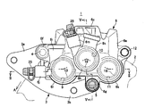
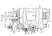
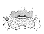
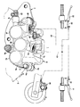
- FIG. 1 is a front view of a vehicle disc brake showing an embodiment of the present invention. It is a top view of the disk brake for vehicles similarly.
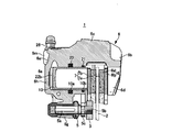
- FIG. 5 is a VV cross-sectional view of FIG. 3.
- FIG. 6 is a sectional view taken along line VI-VI in FIG. 4. It is a system diagram of a brake device.
- the disc brake 1 is used for a front brake of a motorcycle, and includes a caliper bracket 3 fixed to a vehicle body on one side of the disc rotor 2, and a pair of sliding pins 4 and 5 on the caliper bracket 3. And a pair of friction pads 7 and 8 disposed opposite to both sides of the disk rotor 2.
- An arrow A indicates the direction of rotation of the disc rotor 2 that rotates integrally with the front wheels when the vehicle moves forward, and the disk unloading side and the disk loading side described below are those when the vehicle moves forward.
- the caliper body 6 includes an action portion 6a and a reaction portion 6b disposed on both sides of the disc rotor 2, and a bridge portion 6c that connects the action portion 6a and the reaction portion 6b across the outer periphery of the disc rotor 2.
- the three cylinder holes 9, 10, 11 formed in the action portion 6a are divided into two hydraulic systems and are configured as a three-pot two-system system.
- the cylinder holes 9, 10, and 11 are arranged in parallel in the action portion 6a so as to open the disk rotor side, and four reaction force claws 6d are formed in the reaction portion 6b.
- Guide arms 6e and 6e of the hanger pins 12 that suspend the friction pads 7 and 8 project from the disk rotor return side of the action part 6a and the reaction part 6b. On the side, mounting arms 6f and 6g of the sliding pins 4 and 5 are extended.
- the cylinder holes 9, 10, and 11 are formed such that the cylinder hole 9 on the disk delivery side and the cylinder hole 11 on the disk introduction side are formed on the inner side in the disk radial direction, and the central cylinder hole 10 is formed on the outer side in the disk radial direction. That is, the length L1 from the center P1 of the disc rotor 2 to the center axis C1 of the cylinder hole 9 and the length dimension L2 from the center P1 to the center axis C2 of the cylinder hole 11 are larger than the center hole P10 from the center P1.
- the length dimension L3 to the central axis C3 is longer.
- the central cylinder hole 10 and the disk hole 11 on the disk feed side are formed with a small diameter
- the cylinder hole 9 on the disk feed side is formed with a large diameter
- the cylinder hole 9 on the disk feed side and the disk feed side are formed.
- the central cylinder hole 10 is formed deeper than the cylinder hole 9 on the disk delivery side and the cylinder hole 11 on the disk introduction side at the same depth as the cylinder hole 11.
- a cylinder for the first brake system has a large-diameter cylinder hole 9 formed on the inner side in the disk radial direction on the disk outlet side and a small-diameter cylinder hole 11 formed on the inner side in the disk radial direction on the disk inlet side.
- the cylinder hole 10 is a cylinder hole for the second brake system.
- the cylinder hole bottom side of the caliper body 6 is formed so that the central cylinder hole 10 is formed outside the other cylinder holes 9 and 11 in the disk radial direction and deeper than the other cylinder holes 9 and 11.
- a stepped shape having a protruding portion 6h on the outer side in the disk radial direction of the center portion is formed.
- a large-diameter piston 13 is inserted into the cylinder hole 9 on the disk delivery side via a piston seal 14 and a dust seal 15, and the cylinder hole 11 on the disk entry side has a small diameter and the same length as the piston 13.
- the piston 16 is inserted through the piston seal 17 and the dust seal 18.
- a piston 19 having a small diameter and longer than the pistons 13 and 16 is inserted into the central cylinder hole 10 via a piston seal 20 and a dust seal 21.
- the piston seals 14, 17, 20 and the dust seals 15, 18, 21 are mounted in piston seal grooves 9a, 10a, 11a and dust seal grooves 9b, 10b, 11b formed in the cylinder holes 9, 10, 11, respectively.
- the piston seal groove 10a of the central cylinder hole 10 is formed on the side opposite to the disk rotor than the piston seal grooves 9a, 11a of the other two cylinder holes 9, 11, and is adjacent to the disk circumferential direction.
- 10a and piston seal grooves 10a and 11a are formed so as to be displaced in the disk axial direction and overlap in the disk circumferential direction.
- the dust seal grooves 9b, 10b, and 11b are formed shallower than the piston seal grooves 9a, 10a, and 11a, and are formed on the opening side of the cylinder holes 9, 10, and 11, respectively.
- Hydraulic pressure chambers 22a, 22b, and 22c are defined between the pistons 13, 19, and 16 and the cylinder holes 9, 10, and 11, respectively, and the disk delivery side that serves as the cylinder hole for the first brake system.
- the hydraulic chambers 22 a and 22 c defined between the cylinder holes 9 and 11 on the inlet side and the pistons 13 and 16 are communicated with each other by a communication passage 23 a of the first liquid passage 23.
- a first union boss 6i protrudes outside the acting portion 6a in the radial direction of the disk and on the disk delivery side, and a first bleeder boss 6j projects on the inner side of the disk in the radial direction of the disk.
- a second union boss portion 6k and a second bleeder boss portion 6m protrude from the outer side in the disk radial direction and at the center in the disk circumferential direction.
- the first liquid passage 23 is formed in the first union boss part 6i and communicates with the cylinder hole 9 on the disk delivery side, and is formed in the first bleeder boss part 6j and is provided on the disk delivery side cylinder.
- a first bleeder hole 6o communicating with the hole 9 and a straight hole formed from the first bleeder hole 6o, passing through the inner side of the central cylinder hole 10 in the disk radial direction, and the cylinder hole 9 and the disk on the disk delivery side
- the communication passage 23a is connected to the cylinder hole 11 on the entry side in a straight line.
- the second liquid passage 24 is formed in the second union boss portion 6k and communicates with the central cylinder hole 10 and is formed in the second bleeder boss portion 6m and communicates with the central cylinder hole 10. And a second bleeder hole 6q. Further, bleeder screws 25 and 26 are screwed into the first bleeder hole 6o and the second bleeder hole 6q, respectively.
- the communication passage 23a of the first liquid passage 23 is located on the outer side in the disk radial direction with respect to the imaginary line IL1 that linearly connects the disk radial inner ends of the cylinder hole 9 on the disk delivery side and the cylinder hole 11 on the disk delivery side.
- the communication path 23a and the first bleeder hole 6o are formed in a straight line.
- the processing of the communication path 23a and the first bleeder hole 6o is performed by drilling from the opening of the first bleeder hole 6o through the cylinder hole 13 to the disk delivery side surface of the cylinder hole 11, thereby One bleeder hole 6o is drilled at a time, and further, a female thread part for screwing the bleeder screw 25 into the opening of the first part bleeder hole 6o is threaded. Further, the central cylinder hole 10 is disposed outside the first liquid passage 23 in the disk radial direction.
- the caliper bracket 3 is a plate-like member that is attached to the bottom case.
- a second mounting portion 3b is provided, and the sliding pins 4 and 5 project in parallel with the disk shaft on the working portion side of the first mounting portion 3a and the second mounting portion 3b.
- the sliding pin 4 on the disk delivery side is inserted into the insertion hole formed in the mounting arm 6f on the disk delivery side, and the sliding pin 4 on the inner circumference side of the disk is attached to the mounting arm 6g on the inner circumference side of the disk.
- the caliper body 6 is inserted through the formed insertion holes, and supported by the slide pins 4 so as to be movable in the disk axial direction.
- the sliding pin 4 on the disk delivery side has a male thread portion inserted through the caliper bracket through-hole from the working portion side of the caliper bracket 3, and the flange portion 4a is brought into contact with the side of the caliper bracket acting portion.
- the sleeve nut 4 b is screwed onto the male thread portion protruding from the reaction portion to the side of the reaction portion, and the caliper bracket 3 is sandwiched between the sleeve nut 4 b and the flange portion 4 a of the slide pin 4. It protrudes in parallel to the disk axis on the working part side.
- the sliding pin 5 on the inner circumference side of the disk is formed between a shaft portion 5a inserted into the insertion hole of the mounting arm 6g, a male screw 5b used for attachment to the caliper bracket 3, and the male screw 5b and the shaft portion 5a. And a hexagonal nut 5c.
- the male screw 5 b is screwed into the female screw hole of the caliper bracket 3 from the action part side, and the nut 5 c is brought into contact with the action part side surface of the caliper bracket 3, so that the slide pin 5 acts on the caliper bracket 3. It protrudes in parallel to the disk axis on the part side.
- the sliding pin 5 attached in this way has a cylinder hole 9 on the disk delivery side and a cylinder hole 11 on the disk delivery side inside the cross section of the sliding pin 5.
- the cylinder portions 6r and 6s are arranged at positions where an imaginary line IL2 that connects the inner ends in the disk radial direction in a straight line passes.
- a hanger pin 12 is laid across the outside of the disk rotor 2 in parallel with the disk shaft.
- the hanger pin 12 suspends the disk insertion side of the friction pads 7 and 8, and the friction.
- the disk delivery sides of the pads 7 and 8 are supported by a caliper bracket 3 and a sleeve nut 4b, respectively.
- the friction pads 7 and 8 are configured by fixing linings 7a and 8a that are in sliding contact with the side surface of the disk rotor 2 to one side surface of the back plates 7b and 8b. Arm portions 7c and 8c each having a pin insertion hole project therefrom. Torque transmission arms 7d and 8d are provided on the disk delivery side of the back plates 7b and 8b, and a semicircular bifurcated piece 8e is provided at the tip of the torque transmission arm 8d on the reaction portion side.
- the friction pad 7 on the working part side is suspended by inserting the hanger pin 12 through the hanger pin insertion hole on the disk insertion side, and supports the torque transmission arm 7d on the disk delivery side with the caliper bracket 3 to provide a piston 13.
- the friction pad 8 on the reaction portion side is suspended by the hanger pin 12 being inserted into the hanger pin insertion hole on the disk insertion side, and the sleeve nut is formed by the bifurcated piece 8e at the tip of the torque transmission arm 8d on the disk supply side.
- 4b is disposed between the reaction force claw 6d and the other side surface of the disk rotor 2 so as to be movable in the disk axial direction.
- the two fluid passages 23, 24 communicate with a known hydraulic master cylinder via a brake hose (not shown) connected to each union hole 6n, 6p.
- the first fluid passage 23 is connected to a first fluid pressure master cylinder 32 that generates fluid pressure by operating the brake lever 31 of the front wheel brake, and the second fluid passage 24 is operated by operating the brake lever 33 of the rear wheel brake. It is connected to a second hydraulic master cylinder 34 that generates hydraulic pressure.
- the hydraulic pressure generated in the first hydraulic master cylinder 32 is introduced into the hydraulic chambers 22a and 22c by the first hydraulic passage 23, and the pistons 13 and 16 are inserted into the cylinder holes 9 and 11 respectively.
- the front wheel is braked by moving forward toward the disc rotor.
- the hydraulic pressure generated in the second hydraulic master cylinder 34 is introduced into the hydraulic chamber 22b by the second hydraulic passage 24, and the piston 19 moves the cylinder hole 10 through the disc rotor.
- the front wheel is braked by moving forward, and the rear wheel disc brake 35 is operated to brake the rear wheel.
- the processing of the communication passage 23a and the first bleeder hole 6o is performed by drilling from the opening of the first bleeder hole 6o to the disk delivery side surface of the cylinder hole 11 through the cylinder hole 13.
- the communication passage 23a and the first bleeder hole 6o can be drilled at a time, and then the internal thread portion can be processed at the opening of the first part bleeder hole 6o. Reduction can be achieved.
- the communication path 23a is formed linearly on the outer side in the disk radial direction with respect to the imaginary line IL1 that linearly connects the disk radial inner ends of the cylinder hole 9 on the disk delivery side and the cylinder hole 11 on the disk delivery side.
- the caliper body 6 can be reduced in size without impairing the air venting performance in the inside 13.
- the sliding pin 5 on the inner circumferential side of the disk has a cylinder in the caliper body 6 that has a cylinder hole 9 on the disk delivery side and a cylinder hole 11 on the disk delivery side inside the cross section of the sliding pin 5. Since the imaginary line IL2 that connects the inner ends in the disk radial direction of the portions 6r and 6s in a straight line is disposed, the mounting arm of the sliding pin 5 projects greatly inward in the disk radial direction as in the prior art.
- the caliper body 6 can be further reduced in size.
- the disk inner circumferential side sliding pin includes a disk hole on the disk feeding side and a cylinder hole on the disk feeding side. You may arrange
- the present invention is not limited to the one provided with three cylinder holes in the action portion, and can also be applied to one provided with four or more cylinder holes.
- the diameter and depth of the cylinder hole are arbitrary, and each union hole and the second bleeder hole may be appropriately formed according to the shape of the cylinder hole or caliper body.
- the hydraulic master cylinder may be one that generates hydraulic pressure by operating a brake pedal, and pulls connecting means such as a wire by operating a brake operator to generate hydraulic pressure in the hydraulic master cylinder. Things can be used.
Landscapes
- Engineering & Computer Science (AREA)
- General Engineering & Computer Science (AREA)
- Mechanical Engineering (AREA)
- Braking Arrangements (AREA)
Abstract
Description
Claims (3)
- ディスクロータの側部に配置する作用部に、3個以上のシリンダ孔をディスク周方向に並設し、少なくとも何れか2個のシリンダ孔を第1ブレーキ系統用シリンダ孔とし、その他のシリンダ孔を第2ブレーキ系統用シリンダ孔とし、少なくとも1個の第2ブレーキ系統用シリンダ孔を2個の第1ブレーキ系統用シリンダ孔の間に配置し、複数の第1ブレーキ系統用シリンダ孔を連通路によって連通し、前記第1ブレーキ系統用シリンダ孔に挿入されたピストンを、第1液通路を介して供給される作動液によって作動させ、前記第2ブレーキ系統用シリンダ孔に挿入されたピストンを、第2液通路を介して供給される作動液にて作動させると共に、前記第1液通路に第1ユニオン孔と第1ブリーダ孔とを開口し、前記第2液通路に第2ユニオン孔と第2ブリーダ孔とを開口した2系統式の車両用ディスクブレーキのキャリパボディにおいて、前記連通路と前記第1ブリーダ孔とは、前記複数の第1ブレーキ系統用シリンダ孔のディスク半径方向内端を直線状に繋ぐ仮想線よりもディスク半径方向外側に一直線状に形成され、前記第2ブレーキ系統用シリンダ孔は、前記連通路よりもディスク半径方向外側に設けられることを特徴とする車両用ディスクブレーキのキャリパボディ。
- 前記キャリパボディは、車体に取り付けたキャリパブラケットに、車両前進時におけるディスク回出側とディスク内周側とに設けられた一対の摺動ピンを介してディスク軸方向へ移動可能に支持され、ディスク内周側の摺動ピンは、該摺動ピンの断面内を、内部に前記複数の第1ブレーキ系統用シリンダ孔を備えたシリンダ部のディスク半径方向内端を直線状に繋ぐ仮想線が通る位置もしくは該仮想線よりもディスク半径方向外側に配置されることを特徴とする請求項1記載の車両用ディスクブレーキのキャリパボディ。
- ディスクロータの側部に配置する作用部に、3個のシリンダ孔をディスク周方向に並設し、車両前進時におけるディスク回入側とディスク回出側とに配置される2個のシリンダ孔を第1ブレーキ系統用シリンダ孔とし、中央のシリンダ孔を第2ブレーキ系統用シリンダ孔とし、前記2個の第1ブレーキ系統用シリンダ孔を連通路によって連通し、前記第1ブレーキ系統用シリンダ孔に挿入されたピストンを、第1液通路を介して供給される作動液によって作動させ、前記第2ブレーキ系統用シリンダ孔に挿入されたピストンを、第2液通路を介して供給される作動液にて作動させると共に、前記第1液通路に第1ユニオン孔と第1ブリーダ孔とを開口し、前記第2液通路に第2ユニオン孔と第2ブリーダ孔とを開口した2系統式の車両用ディスクブレーキのキャリパボディにおいて、該キャリパボディは、前記ディスクロータの一側部に配置される前記作用部と、前記ディスクロータの他側部に配置される反作用部と、該反作用部と前記作用部とを前記ディスクロータの外周を跨いで連結するブリッジ部とで構成され、前記連通路と前記第1ブリーダ孔とは、前記2個の第1ブレーキ系統用シリンダ孔のディスク半径方向内端を直線状に繋ぐ仮想線よりもディスク半径方向外側に一直線状に形成され、前記第2ブレーキ系統用シリンダ孔は、前記連通路よりもディスク半径方向外側に設けられることを特徴とする車両用ディスクブレーキのキャリパボディ。
Priority Applications (5)
| Application Number | Priority Date | Filing Date | Title |
|---|---|---|---|
| US13/201,376 US8733515B2 (en) | 2009-02-12 | 2010-02-10 | Caliper body for disc brake for vehicle |
| EP10741244.7A EP2397718B1 (en) | 2009-02-12 | 2010-02-10 | Caliper body for disc brake for vehicle |
| BRPI1007760A BRPI1007760B8 (pt) | 2009-02-12 | 2010-02-10 | corpo de pinça para um freio a disco para um veículo |
| CN201080007585XA CN102317641B (zh) | 2009-02-12 | 2010-02-10 | 车辆用盘式制动器的钳体 |
| ES10741244.7T ES2643227T3 (es) | 2009-02-12 | 2010-02-10 | Cuerpo de pinza para freno de disco para vehículo |
Applications Claiming Priority (2)
| Application Number | Priority Date | Filing Date | Title |
|---|---|---|---|
| JP2009029348A JP4892571B2 (ja) | 2009-02-12 | 2009-02-12 | 車両用ディスクブレーキのキャリパボディ |
| JP2009-029348 | 2009-02-12 |
Publications (1)
| Publication Number | Publication Date |
|---|---|
| WO2010092967A1 true WO2010092967A1 (ja) | 2010-08-19 |
Family
ID=42561809
Family Applications (1)
| Application Number | Title | Priority Date | Filing Date |
|---|---|---|---|
| PCT/JP2010/051925 Ceased WO2010092967A1 (ja) | 2009-02-12 | 2010-02-10 | 車両用ディスクブレーキのキャリパボディ |
Country Status (8)
| Country | Link |
|---|---|
| US (1) | US8733515B2 (ja) |
| EP (1) | EP2397718B1 (ja) |
| JP (1) | JP4892571B2 (ja) |
| CN (1) | CN102317641B (ja) |
| BR (1) | BRPI1007760B8 (ja) |
| ES (1) | ES2643227T3 (ja) |
| TW (1) | TWI399494B (ja) |
| WO (1) | WO2010092967A1 (ja) |
Cited By (1)
| Publication number | Priority date | Publication date | Assignee | Title |
|---|---|---|---|---|
| TWI879861B (zh) * | 2020-03-30 | 2025-04-11 | 日商日立安斯泰莫股份有限公司 | 車輛用碟式煞車之卡鉗本體安裝構造 |
Families Citing this family (13)
| Publication number | Priority date | Publication date | Assignee | Title |
|---|---|---|---|---|
| JP5960176B2 (ja) * | 2014-02-18 | 2016-08-02 | 日信工業株式会社 | 車両用ディスクブレーキのキャリパボディ及びその製造方法 |
| CN104943802A (zh) * | 2014-03-28 | 2015-09-30 | 光阳工业股份有限公司 | 碟式刹车卡钳装置 |
| TWI551788B (zh) * | 2014-07-28 | 2016-10-01 | Kwang Yang Motor Co | Disc Brake Calipers |
| CN105314044B (zh) * | 2014-07-30 | 2018-11-02 | 光阳工业股份有限公司 | 碟式刹车卡钳装置 |
| ES2868825T3 (es) * | 2016-05-06 | 2021-10-22 | Nissin Kogyo Kk | Freno de disco para vehículos |
| EP3473881B1 (en) | 2016-06-20 | 2021-10-06 | Hitachi Astemo, Ltd. | Caliper body for vehicle disc brake |
| US10539199B2 (en) * | 2017-01-20 | 2020-01-21 | Akebono Brake Industry Co., Ltd | Multi-piston caliper |
| JP6871829B2 (ja) * | 2017-09-06 | 2021-05-12 | 曙ブレーキ工業株式会社 | 対向ピストン型ディスクブレーキ用キャリパ |
| DE102019219811A1 (de) * | 2019-12-17 | 2021-06-17 | Shimano Inc. | Scheibenbremssattel |
| TWI735298B (zh) * | 2020-07-29 | 2021-08-01 | 國立屏東科技大學 | 前後碟剎機車之剎車系統 |
| EP4253176B1 (en) * | 2020-11-27 | 2026-03-25 | Astemo, Ltd. | Caliper body of disc brake for vehicle |
| GB2614226B (en) * | 2021-09-14 | 2026-03-18 | Ap Racing Ltd | Braking system |
| CN114278683B (zh) * | 2021-12-31 | 2024-11-22 | 武汉万向汽车制动器有限公司 | 低动态需液量铝质制动钳 |
Citations (7)
| Publication number | Priority date | Publication date | Assignee | Title |
|---|---|---|---|---|
| JPH047739U (ja) * | 1990-05-10 | 1992-01-23 | ||
| JPH0579071U (ja) | 1992-03-31 | 1993-10-26 | 日信工業株式会社 | 車両用ディスクブレーキのキャリパボディ |
| JPH1030660A (ja) * | 1996-07-16 | 1998-02-03 | Nissin Kogyo Kk | 液圧式車両用ディスクブレーキのピストン対向型キャリパボディ |
| JP2003148524A (ja) * | 2001-11-14 | 2003-05-21 | Nissin Kogyo Co Ltd | 車両用ディスクブレーキのキャリパボディ |
| JP2003166566A (ja) * | 2001-11-29 | 2003-06-13 | Nissin Kogyo Co Ltd | 車両用ディスクブレーキのキャリパボディ |
| JP2006153264A (ja) | 2004-10-26 | 2006-06-15 | Nissin Kogyo Co Ltd | 車両用ディスクブレーキのキャリパボディ |
| JP2008240862A (ja) * | 2007-03-27 | 2008-10-09 | Honda Motor Co Ltd | 車両用ディスクブレーキ |
Family Cites Families (7)
| Publication number | Priority date | Publication date | Assignee | Title |
|---|---|---|---|---|
| US3734248A (en) * | 1971-12-01 | 1973-05-22 | C Fay | Floating caliper assembly for distribution of brake shoe thrust in dual hydraulic brake system |
| US5363943A (en) * | 1991-10-15 | 1994-11-15 | Honda Giken Kogyo Kabushiki Kaisha | Disk brake apparatus for vehicle |
| CN2729419Y (zh) * | 2004-06-09 | 2005-09-28 | 陈利祥 | 汽车液压拳式浮钳型双活塞盘式制动器 |
| JP4713318B2 (ja) * | 2005-11-28 | 2011-06-29 | 日信工業株式会社 | 車両用ディスクブレーキのキャリパボディ |
| GB2451690B (en) | 2007-08-10 | 2009-08-05 | Ap Racing Ltd | A disc brake caliper body and a disc brake caliper comprising such a body |
| JP4988637B2 (ja) * | 2008-03-27 | 2012-08-01 | 本田技研工業株式会社 | ディスクブレーキ装置 |
| TWM343636U (en) | 2008-03-31 | 2008-11-01 | Jian-Hua Chen | Structural improvement of a caliper |
-
2009
- 2009-02-12 JP JP2009029348A patent/JP4892571B2/ja active Active
-
2010
- 2010-02-10 EP EP10741244.7A patent/EP2397718B1/en active Active
- 2010-02-10 BR BRPI1007760A patent/BRPI1007760B8/pt active IP Right Grant
- 2010-02-10 CN CN201080007585XA patent/CN102317641B/zh active Active
- 2010-02-10 WO PCT/JP2010/051925 patent/WO2010092967A1/ja not_active Ceased
- 2010-02-10 ES ES10741244.7T patent/ES2643227T3/es active Active
- 2010-02-10 US US13/201,376 patent/US8733515B2/en active Active
- 2010-02-12 TW TW099104677A patent/TWI399494B/zh active
Patent Citations (7)
| Publication number | Priority date | Publication date | Assignee | Title |
|---|---|---|---|---|
| JPH047739U (ja) * | 1990-05-10 | 1992-01-23 | ||
| JPH0579071U (ja) | 1992-03-31 | 1993-10-26 | 日信工業株式会社 | 車両用ディスクブレーキのキャリパボディ |
| JPH1030660A (ja) * | 1996-07-16 | 1998-02-03 | Nissin Kogyo Kk | 液圧式車両用ディスクブレーキのピストン対向型キャリパボディ |
| JP2003148524A (ja) * | 2001-11-14 | 2003-05-21 | Nissin Kogyo Co Ltd | 車両用ディスクブレーキのキャリパボディ |
| JP2003166566A (ja) * | 2001-11-29 | 2003-06-13 | Nissin Kogyo Co Ltd | 車両用ディスクブレーキのキャリパボディ |
| JP2006153264A (ja) | 2004-10-26 | 2006-06-15 | Nissin Kogyo Co Ltd | 車両用ディスクブレーキのキャリパボディ |
| JP2008240862A (ja) * | 2007-03-27 | 2008-10-09 | Honda Motor Co Ltd | 車両用ディスクブレーキ |
Non-Patent Citations (1)
| Title |
|---|
| See also references of EP2397718A4 * |
Cited By (1)
| Publication number | Priority date | Publication date | Assignee | Title |
|---|---|---|---|---|
| TWI879861B (zh) * | 2020-03-30 | 2025-04-11 | 日商日立安斯泰莫股份有限公司 | 車輛用碟式煞車之卡鉗本體安裝構造 |
Also Published As
| Publication number | Publication date |
|---|---|
| US20110290600A1 (en) | 2011-12-01 |
| BRPI1007760A2 (pt) | 2016-02-23 |
| US8733515B2 (en) | 2014-05-27 |
| EP2397718A1 (en) | 2011-12-21 |
| BRPI1007760B1 (pt) | 2020-08-18 |
| EP2397718A4 (en) | 2016-03-30 |
| JP2010185502A (ja) | 2010-08-26 |
| TWI399494B (zh) | 2013-06-21 |
| JP4892571B2 (ja) | 2012-03-07 |
| EP2397718B1 (en) | 2017-06-28 |
| CN102317641B (zh) | 2013-07-17 |
| TW201033494A (en) | 2010-09-16 |
| BRPI1007760B8 (pt) | 2020-09-01 |
| CN102317641A (zh) | 2012-01-11 |
| ES2643227T3 (es) | 2017-11-21 |
Similar Documents
| Publication | Publication Date | Title |
|---|---|---|
| JP4892571B2 (ja) | 車両用ディスクブレーキのキャリパボディ | |
| CN103133567B (zh) | 盘式制动器 | |
| US7937940B2 (en) | Master cylinder comprising a resupply-promoting seal | |
| CN101725649A (zh) | 钳盘式制动器 | |
| JP2015152130A (ja) | 車両用ディスクブレーキのキャリパボディ | |
| JP2010185501A (ja) | 車両用ディスクブレーキ | |
| EP3473881B1 (en) | Caliper body for vehicle disc brake | |
| JP2010185500A (ja) | 車両用ディスクブレーキのキャリパボディ | |
| JP4474474B2 (ja) | ピンスライド型車両用ディスクブレーキ | |
| CN113775678B (zh) | 电子钳式制动器及其操作方法 | |
| JP2009264506A (ja) | 車両用ディスクブレーキ | |
| JP2010185503A (ja) | 車両用ディスクブレーキのキャリパボディ | |
| JPWO2019003707A1 (ja) | キャリパボディおよびディスクブレーキ | |
| JP4836918B2 (ja) | 車両用ディスクブレーキのキャリパボディ | |
| JP4169685B2 (ja) | 車両用ディスクブレーキのキャリパボディ | |
| JP2006105326A (ja) | 車両用ディスクブレーキ | |
| JP4713318B2 (ja) | 車両用ディスクブレーキのキャリパボディ | |
| JP4726918B2 (ja) | 車両用ディスクブレーキのキャリパボディ | |
| JPH10218067A (ja) | バーハンドル車両用二系統式ディスクブレーキ装置 | |
| CN221068043U (zh) | 车辆制动器、制动系统和车辆 | |
| JP2013123968A (ja) | 自動二輪車用ブレーキ装置 | |
| CN104246271B (zh) | 盘式制动器 | |
| JPS62377B2 (ja) | ||
| JP2013155799A (ja) | 車両用ディスクブレーキ | |
| JPH10218068A (ja) | バーハンドル車両用二系統式ディスクブレーキ装置 |
Legal Events
| Date | Code | Title | Description |
|---|---|---|---|
| WWE | Wipo information: entry into national phase |
Ref document number: 201080007585.X Country of ref document: CN |
|
| 121 | Ep: the epo has been informed by wipo that ep was designated in this application |
Ref document number: 10741244 Country of ref document: EP Kind code of ref document: A1 |
|
| REEP | Request for entry into the european phase |
Ref document number: 2010741244 Country of ref document: EP |
|
| WWE | Wipo information: entry into national phase |
Ref document number: 2010741244 Country of ref document: EP |
|
| WWE | Wipo information: entry into national phase |
Ref document number: 5992/DELNP/2011 Country of ref document: IN |
|
| NENP | Non-entry into the national phase |
Ref country code: DE |
|
| WWE | Wipo information: entry into national phase |
Ref document number: 13201376 Country of ref document: US |
|
| REG | Reference to national code |
Ref country code: BR Ref legal event code: B01A Ref document number: PI1007760 Country of ref document: BR |
|
| ENP | Entry into the national phase |
Ref document number: PI1007760 Country of ref document: BR Kind code of ref document: A2 Effective date: 20110809 |