WO2010095565A1 - インクジェット記録装置 - Google Patents
インクジェット記録装置 Download PDFInfo
- Publication number
- WO2010095565A1 WO2010095565A1 PCT/JP2010/052044 JP2010052044W WO2010095565A1 WO 2010095565 A1 WO2010095565 A1 WO 2010095565A1 JP 2010052044 W JP2010052044 W JP 2010052044W WO 2010095565 A1 WO2010095565 A1 WO 2010095565A1
- Authority
- WO
- WIPO (PCT)
- Prior art keywords
- nozzle
- ink
- recording head
- scanning direction
- recording
- Prior art date
- Legal status (The legal status is an assumption and is not a legal conclusion. Google has not performed a legal analysis and makes no representation as to the accuracy of the status listed.)
- Ceased
Links
Images


Classifications
-
- B—PERFORMING OPERATIONS; TRANSPORTING
- B41—PRINTING; LINING MACHINES; TYPEWRITERS; STAMPS
- B41J—TYPEWRITERS; SELECTIVE PRINTING MECHANISMS, i.e. MECHANISMS PRINTING OTHERWISE THAN FROM A FORME; CORRECTION OF TYPOGRAPHICAL ERRORS
- B41J2/00—Typewriters or selective printing mechanisms characterised by the printing or marking process for which they are designed
- B41J2/005—Typewriters or selective printing mechanisms characterised by the printing or marking process for which they are designed characterised by bringing liquid or particles selectively into contact with a printing material
- B41J2/01—Ink jet
- B41J2/21—Ink jet for multi-colour printing
- B41J2/2132—Print quality control characterised by dot disposition, e.g. for reducing white stripes or banding
-
- B—PERFORMING OPERATIONS; TRANSPORTING
- B41—PRINTING; LINING MACHINES; TYPEWRITERS; STAMPS
- B41J—TYPEWRITERS; SELECTIVE PRINTING MECHANISMS, i.e. MECHANISMS PRINTING OTHERWISE THAN FROM A FORME; CORRECTION OF TYPOGRAPHICAL ERRORS
- B41J2/00—Typewriters or selective printing mechanisms characterised by the printing or marking process for which they are designed
- B41J2/005—Typewriters or selective printing mechanisms characterised by the printing or marking process for which they are designed characterised by bringing liquid or particles selectively into contact with a printing material
- B41J2/01—Ink jet
- B41J2/135—Nozzles
- B41J2/145—Arrangement thereof
Definitions
- the present invention relates to an ink jet recording apparatus, and more particularly, to an ink jet recording apparatus using a recording head in which staggered nozzles are driven in multiple phases.
- a recording head As an image recording apparatus capable of recording an image not only on a normal base material such as paper or fabric but also on a base material having a low ink absorbability such as a resin film (hereinafter referred to as a recording medium), a recording head An ink jet recording apparatus has been developed in which ink is ejected from a nozzle provided on one end face (that is, a so-called nozzle face) and landed on a substrate, and the technique is currently applied in various technical fields.
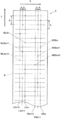
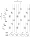
- a recording head used in the ink jet recording apparatus a recording head in which nozzles are arranged in a line on the nozzle surface is often used, but in recent years, as shown in a plan view of FIG.
- a print head having nozzle rows 3m, 3m + 1, and 3m + 2 composed of three rows in which the nozzles N are staggered in the main scanning direction X indicated by the arrow X in the figure at a predetermined interval is often used.
- FIG. 24 there is a recording medium S below the recording head H, that is, in the rear side in the figure, and the surface of the recording head H facing the recording medium S is a nozzle surface P, and each nozzle N is Is formed.
- the arrangement of the nozzles N in which the nozzle positions of the adjacent nozzles N are shifted in the main scanning direction X is referred to as a staggered arrangement.
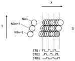
- the nozzles N3m + 1 and N3m + 2 are also arranged in a row in the sub-scanning direction Y.
- the interval p between the nozzles N3m, N3m + 1, and N3m + 2 is usually 1/3 or 2/3 of the pixel pitch L of the recording medium S. That is, it is formed to be L / 3 or 2L / 3. Further, the interval q in the sub-scanning direction Y between adjacent nozzles N is usually formed to be the same as the pixel pitch L.
- the nozzle row formed with +1 is referred to as nozzle row 3m + 1
- the nozzle row formed with the nozzles N3m + 2 with the nozzle number represented by 3m + 2 is referred to as nozzle row 3m + 2.
- the staggered nozzles N are normally driven in multiple phases.
- each nozzle N3m, N3m + 1 is provided in the recording head H arranged in a staggered manner for each of the three nozzles N as shown in FIG. 24, each nozzle N3m, N3m + 1 is provided.
- N3m + 2 is driven in three phases.
- Conventional three-phase driving of the nozzles N3m, N3m + 1, and N3m + 2 is performed as follows.
- the strobe pulse is switched from STB1 to STB2 and applied to each nozzle N3m + 1 of the nozzle array 3m + 1.
- the drive pulse is applied, ink is ejected to the recording medium S from each nozzle N3m + 1 of the nozzle row 3m + 1 to which the strobe pulse STB2 is applied.
- the nozzle N3m + 1 is located behind the nozzle N3m by L / 3 in the movement direction of the recording head H in the main scanning direction X, the ink ejected from each nozzle N3m + 1 is the recording medium S.
- the ink landed in the sub-scanning direction Y of the ink ejected from each nozzle N3m is landed.
- the strobe pulse is switched from STB2 to STB3 and applied to each nozzle N3m + 2 of the nozzle array 3m + 2.
- a drive pulse is applied in this state, ink is ejected from the nozzles N3m + 2 of the nozzle array 3m + 2 to the recording medium S, and the ink ejected from the nozzles N3m + 2
- the ink ejected from each nozzle N3m + 1 is landed at a position adjacent to the sub-scanning direction Y of the landed ink.
- the strobe pulse is switched in the order of STB 1 ⁇ STB 2 ⁇ STB 3 to switch the drive phase, whereby the ink ejected from each nozzle N 3 m to N 3 m + 2 extends in the sub-scanning direction Y on the recording medium S. Can be landed in a straight line.
- the nozzle N for ejecting ink is switched in order from the nozzle N3m at the forefront in the moving direction of the recording head H in the main scanning direction X to the nozzles N3m + 1 and N3m + 2 on the rear side.
- the method of switching the phase is called the rank phase.
- each nozzle N3m in the nozzle row 3m moves in the main scanning direction X by the pixel pitch L from the position where ink was first ejected. Come in position.
- a strobe pulse is switched from STB3 to STB1 and a drive pulse is applied to each nozzle N3m in the nozzle array 3m
- each nozzle N3m in the nozzle array 3m starts from the position where ink was first ejected.
- Ink is ejected at a position shifted in the main scanning direction X by the pitch L. Therefore, the ink is landed at a position adjacent to the position where the ink is first ejected from each nozzle N3m of the nozzle array 3m and landed on the recording medium S.
- the strobe pulse is switched from STB1 to STB2 and STB3 in order and extends on the recording medium S in the sub-scanning direction Y.
- the ink is landed in a straight line, and the ink is further landed in a straight line at a position adjacent to the main scanning direction X of the ink straight line.
- the ink is landed on each pixel of the recording medium S in such a manner that the operation of landing the ink on the recording medium S in a straight line extending in the sub-scanning direction Y is repeated.
- an image was recorded on the recording medium S.
- the strobe pulse is switched in the order of STB1, STB2, and STB3, and the nozzle N for ejecting ink is set to the recording head.
- the nozzle N3m at the forefront of the movement direction of H is switched in order from the nozzles N3m + 1 and N3m + 2 on the rear side.
- the recording head H when the recording head H performs image recording while moving to the left in the figure, the recording head H Since the nozzle N on the foremost side in the moving direction replaces the nozzle N3m + 2, the nozzle N that ejects ink is switched in order from the nozzle N3m + 2 on the foremost side in the moving direction of the recording head H to the nozzles N3m + 1 and N3m on the rear side.
- the strobe pulse is switched in the order of STB3 ⁇ STB2 ⁇ STB1.
- the moving speed of the recording head H in the main scanning direction X is doubled so that ink is ejected from the same nozzle N every other pixel.
- another recording head H * having a staggered nozzle M is provided in parallel with the recording head H in the main scanning direction X.
- a staggered nozzle M is provided in parallel with the nozzle N in the main scanning direction X on the recording head H provided with the arranged nozzles N.
- the nozzle M is also driven to discharge in the opposite phase.
- the ink is ejected from the nozzle M and landed on the gap portion of the ink ejected from the nozzle N and landed on the recording medium S, and the image is recorded on the recording medium S.
- the strobe pulses STB1 to STB3 when the pulse widths of the strobe pulses STB1 to STB3 (the time interval at which the pulses are at the high level) are shown in FIG. Although it is described as if it has become twice the width, this is because the moving speed of the recording head H has doubled, and the pulse widths of the strobe pulses STB1 to STB3 do not change.
- the ink jet recording apparatus is a line head system, and an image is recorded by ejecting ink to all pixels of the recording medium while the recording medium moves once relative to the recording head. Is the premise. That is, image recording must be performed in a so-called one pass.
- each nozzle of the recording head is driven to discharge in the opposite phase, and the moving speed of the recording head relative to the recording medium is doubled from the conventional moving speed, so that ink is discharged from the nozzle N every other pixel and landed.
- another recording head having a staggered nozzle M is arranged in parallel with the recording head H in the main scanning direction X, or a staggered nozzle is provided. It has become necessary to provide a staggered nozzle M in parallel with the nozzle N in the main scanning direction X on the recording head H provided with N.
- the recording head H having the staggered nozzles N and the recording head having the staggered nozzles M are provided separately, the cost increases by the newly provided recording head. Further, the adjustment operation of the positions of the nozzles N and M of each recording head becomes complicated, and various problems such as the necessity of appropriately adjusting the discharge timing of the nozzles N and M arise. In addition, when both the staggered nozzles N and M are provided in the recording head H, there is a problem that such a dedicated recording head must be newly manufactured.
- the present invention has been made in view of the above problems, and in a serial head type ink jet recording apparatus using a recording head in which nozzles are staggered, a streak pattern is generated in an image on a recording medium.
- An object of the present invention is to provide an ink jet recording apparatus capable of improving the image quality of a recorded image.
- an ink jet recording apparatus is: A recording head having three nozzle rows in which a plurality of nozzles are staggered at L / 3 intervals in the main scanning direction when driven at a driving phase of three phases and a pixel pitch is L; Each nozzle row of the recording head is driven to discharge in order from the last nozzle row in the relative movement direction of the recording head to the recording medium to the front nozzle row, and the discharge frequency for each nozzle row of the recording head is set to f.
- the recording head includes two sets of nozzle rows each including the three rows, and the two nozzle rows are arranged in parallel in the main scanning direction.
- the interval in the sub-scanning direction between adjacent nozzles in the same nozzle row set is set to be twice the pixel pitch, and the nozzles in one set of nozzle rows are in the other set. It is characterized in that it is provided by being shifted by one pixel pitch in the sub-scanning direction with respect to the nozzles in the nozzle row.
- the recording head includes two sets of nozzle rows each including the three rows, and the two sets of nozzle rows are arranged in parallel in the main scanning direction.
- the interval in the sub-scanning direction between adjacent nozzles in the same nozzle row set is set to 4 times the pixel pitch, and the nozzles in one set of nozzle rows are in the other set. It is characterized by being provided with a shift of two pixel pitches in the sub-scanning direction with respect to the nozzles of the nozzle row.
- the control unit is configured to perform a single scan in the main scanning direction of the recording head. With respect to the ink ejection operation from each nozzle for each ejection cycle to be performed, a discharge cycle for ejecting ink from each nozzle and a ejection cycle for not ejecting ink from each nozzle are provided.
- the ink that has not been ejected from the nozzle should naturally land. Since the ink ejected from another normal nozzle is landed and filled in the pixel position adjacent to the pixel position, the portion where the ink is not ejected in the image recorded on the recording medium continues in the main scanning direction. Arrangement is prevented, and a phenomenon in which a streak-like pattern appears in the image is avoided. For this reason, it is possible to suppress deterioration in image quality and improve image quality.
- an image can be recorded on the recording medium by one scanning of the recording head (so-called one pass).
- the recording method of the present invention an image is recorded on the recording medium.
- the recording head needs to be scanned twice (so-called two passes), since the moving speed of the recording head in the main scanning direction is twice the conventional moving speed, the time required for image recording is the conventional recording method. It is not much different from the case of. That is, according to the first aspect of the present invention, it is possible to avoid the phenomenon of streak-like patterns in an image, which could not be avoided by the conventional recording technique, in the same recording time as that of the conventional recording technique. Is possible.
- the recording head includes two sets of three nozzle rows, and the two nozzle rows are arranged in parallel in the main scanning direction, and are adjacent to each other in the same nozzle row set.
- the interval between the nozzles in the sub-scanning direction is set to twice the pixel pitch, and the nozzles in one set of nozzle rows are one pixel pitch in the sub-scanning direction with respect to the nozzles in the other set of nozzle rows.
- the recording head includes two sets of three nozzle rows, and the two nozzle rows are arranged in parallel in the main scanning direction and are adjacent to each other in the same nozzle row set.
- the interval between the nozzles in the sub-scanning direction is set to four times the pixel pitch, and the nozzles in one set of nozzle rows are two pixel pitches in the sub-scanning direction with respect to the nozzles in the other set of nozzle rows.
- the ink is discharged from the nozzle N.
- Multiple pixel positions in the area between non-ejected pixel positions are filled with multiple inks ejected from different normal nozzles, so that pixel positions where no ink is ejected diffusely in the image
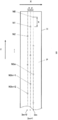
- FIG. 1 is a schematic perspective view illustrating an overall configuration of an ink jet recording apparatus.
- FIG. 4 is an enlarged view of a carriage portion including a recording head.
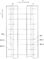
- FIG. 3 is a plan view illustrating a configuration of a recording head.
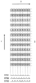
- FIG. 6 is a diagram illustrating pixel positions and strobe pulses where ink is landed when ink is ejected by a conventional recording method in the first embodiment.
- It is a schematic perspective view which shows the structure containing the head drive circuit of a carriage upper part.
- It is a figure which shows the structure of a head drive circuit.
- It is a figure which shows the example of the drive waveform of a nozzle drive signal.
- It is a block diagram which shows the control structure of an inkjet recording device.
- FIG. 1 is a schematic perspective view illustrating an overall configuration of an ink jet recording apparatus.
- FIG. 4 is an enlarged view of a carriage portion including a recording head.
- FIG. 3 is a plan view
- FIG. 4 is a diagram illustrating pixel positions and the like where ink is landed when ink is ejected from an ink column on the right side of the recording head by the recording method of the present invention in the first embodiment.
- FIG. 3 is a diagram illustrating pixel positions and the like where ink is landed when ink is ejected from the left and right ink columns of the recording head by the recording method of the present invention in the first embodiment.
- FIG. 11 is a diagram illustrating a pixel position in FIG. 10 and a pixel position where ink is landed by scanning in the opposite direction of the recording head. It is a figure which shows the pixel position in the image in which ink is not discharged from a nozzle in 1st Embodiment.
- FIG. 10 is a diagram illustrating pixel positions and strobe pulses where ink is landed when ink is ejected by a conventional recording method in the second embodiment.
- FIG. 10 is a diagram illustrating a pixel position where ink is landed when ink is ejected from an ink column on the right side of a recording head by the recording method of the present invention in a second embodiment.
- FIG. 10 is a diagram illustrating pixel positions and the like where ink is landed when ink is ejected from the left and right ink columns of the recording head by the recording method of the present invention in the second embodiment.
- FIG. 19 is a diagram illustrating a pixel position in FIG. 18 and a pixel position where ink is landed by scanning in the opposite direction of the recording head.
- FIG. 10 is a diagram illustrating pixel positions and the like where ink is landed when ink is ejected from an ink column on the right side of a recording head by the recording method of the present invention in a third embodiment.
- FIG. 10 is a diagram illustrating pixel positions and the like where ink is landed when ink is ejected from the left and right ink columns of a recording head by the recording method of the present invention in a third embodiment.
- FIG. 22 is a diagram illustrating a pixel position in FIG. 21 and a pixel position where ink is landed by scanning in the opposite direction of the recording head. It is a figure which shows the pixel position in the image in which an ink is not discharged from a nozzle in 3rd Embodiment.
- FIG. 10 is a diagram illustrating pixel positions and the like where ink is landed when ink is ejected from an ink column on the right side of a recording head by the recording method of the present invention in a third embodiment.
- FIG. 3 is a plan view showing a configuration of a general recording head having nozzle rows composed of three rows arranged in a staggered manner.
- FIG. 25 is a diagram illustrating pixel positions and strobe pulses where ink is landed when ink is ejected by the conventional recording method using the recording head of FIG. 24.
- FIG. 26 is a diagram illustrating pixel positions in an image where ink is not ejected from nozzles when ink is ejected by the conventional recording method of FIG. 25.
- FIG. 25 is a diagram illustrating pixel positions where ink is landed when ink is ejected from the recording head of FIG. 24 by the recording method described in Patent Document 2.
- FIG. 25 is a diagram illustrating pixel positions where ink is landed when ink is ejected from the recording head of FIG. 24 by the recording method described in Patent Document 2.
- FIG. 3 is a plan view showing a configuration in which two recording heads are arranged in parallel in the main scanning direction.
- FIG. 3 is a plan view showing a configuration in which a staggered nozzle array is arranged in parallel in the main scanning direction on one recording head.
- FIG. 30 is a diagram illustrating pixel positions where ink is landed when ink is ejected using the recording head of FIG. 28 or FIG. 29.
- the ink jet recording apparatus 1 As shown in FIG. 1, the ink jet recording apparatus 1 according to the first embodiment mainly includes a transport unit 2, a main scanning unit 3, and a computer 4.
- FIG. 2 is an enlarged view of a carriage 32 portion including a recording head 5 described later in the internal structure of the main scanning unit 3.
- a driving roller 21 extending in the main scanning direction X and a driven roller are rotatably supported on the upper portion of the transport unit 2, and the driving roller 21 is rotationally driven on one end side of the driving roller 21.
- a drive motor 22 is attached.
- An endless conveying belt 23 is stretched between the driving roller 21 and the driven roller. The conveying belt 23 circulates between the driving roller 21 and the driven roller when the driving roller 21 rotates.
- the drive motor 22 rotates the drive roller 21 by a predetermined amount to move the recording medium S in the transport direction when the recording head 5 finishes one scan in the main scanning direction X according to the control of the control means 9 described later.
- the driving roller 21 is rotated again by a predetermined amount to convey the recording medium S in the conveying direction Z.
- the recording medium S is repeatedly conveyed by a predetermined distance and stopped so that the recording medium S is intermittently conveyed.
- the conveyance direction Z of the recording medium S is set to be parallel to the sub-scanning direction Y orthogonal to the main scanning direction X. Further, it is not necessary to configure the recording medium S to be transported by the transport belt 23.
- the recording medium S may be configured to move on a flat platen in the transport direction Z (sub-scanning direction Y). Is possible.
- the recording medium S can be made of resin film, metal, or the like in addition to paper and fabric, and is not particularly limited.
- the main scanning unit 3 is disposed above the conveyance belt 23 of the conveyance unit 2. Inside the main scanning unit 3, a rod-shaped carriage rail 31 is disposed so as to extend in the main scanning direction X. On the carriage rail 31, a substantially casing-shaped carriage 32 is arranged in the main scanning direction X. It is supported so that it can reciprocate. The carriage 32 is moved and scanned in the main scanning direction X along the carriage rail 31 by driving of a scanning drive mechanism including a motor (not shown).
- a surface P (hereinafter referred to as a plurality of nozzles N) that discharges ink of each color such as yellow (Y), magenta (M), cyan (C), black (K) and the like when recording an image.
- a plurality of recording heads 5 arranged on the nozzle surface P) are mounted, and ink droplets of each color are ejected from the nozzles N of the recording heads 5 to the recording medium S on the transport belt 23. It is like that.
- the carriage 32 accommodated piping (not shown) for supplying ink from an ink tank 81 to be described later to the recording head 5, wiring (not shown) for transmitting an electric signal and power for driving the recording head 5 and the like.
- a cable bear 33 is connected.
- one end side of the main scanning unit 3 in the main scanning direction X is a maintenance unit 6 for performing maintenance of the recording head 5, and the main scanning unit 3, the nozzles of the recording head 5 during the non-recording operation are arranged so that the nozzles N of the recording head 5 are dried during the non-recording operation and ink discharge from the nozzles N is not defective.
- the nozzle moisturizing unit 7 is used to cap and moisturize the surface P.
- an ink rack 8 including an ink tank 81 for storing each color ink to be supplied to each recording head 5 is disposed behind the main scanning unit 3. Ink is supplied from each ink tank 81 to each recording head 5 via the above-described piping, an ink supply pipe (not shown), or the like.
- the main scanning unit 3 image processing for converting image data of an image to be recorded on a recording medium S input from an external device (not shown) into data corresponding to each nozzle N of the recording head 5.
- the computer 4 is arranged, and data and the like are serially transferred from the computer 4 to a head driving circuit (not shown) that drives the recording head 5 through the wiring described above.
- the computer 4 is configured by a general-purpose computer in which a CPU (Central Processing Unit), a ROM (Read Only Memory), a RAM (Random Access Memory), an input / output interface, and the like (not shown) are connected to a bus. ing.
- a plurality of nozzles N3m, N3m + 1, N3m + 2 as shown in FIG. 24 are arranged in a staggered arrangement in the main scanning direction X at L / 3 intervals.
- an existing recording head as shown in FIG. 3 is used as the recording head 5.
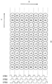
- the recording head 5 is driven for each driving phase composed of three phases, and a plurality of nozzles N are arranged in three rows staggered in the main scanning direction X at L / 3 intervals (L is a pixel pitch). Two sets of nozzle rows are arranged in parallel in the main scanning direction X of the recording head 5.
- the right set of nozzle rows in the figure is represented as R3m, R3m + 1, R3m + 2, and the nozzles belonging to the nozzle rows R3m, R3m + 1, R3m + 2 are represented as nozzles NR3m, NR3m + 1, and NR3m + 2, respectively.
- the left nozzle set is represented as L3m, L3m + 1, L3m + 2, and the nozzles belonging to the nozzle rows L3m, L3m + 1, L3m + 2 are represented as nozzles NL3m, NL3m + 1, and NL3m + 2, respectively.
- a total of 512 nozzles N are formed, with an even number of 256 nozzles for each of the left and right groups.
- the recording head 5 is used to record an image on the recording medium S at a resolution of 360 dpi.
- the pixel pitch L is 70.5 ⁇ m, so that the three nozzle arrays on the left and right are connected to each other.
- the interval p is set to 23.5 ⁇ m, which is 1/3 of the interval p.
- the interval between the corresponding nozzle rows on the left and right that is, the interval between the nozzle row R3m and the nozzle row L3m, the nozzle row R3m + 1 and the nozzle row L3m + 1, and the nozzle row R3m + 2 and the nozzle row L3m + 2 is 1. .44 mm.
- the ejection frequency (that is, the ejection frequency for each nozzle N) f of each nozzle row of the recording head 5 of the present embodiment is set as appropriate, for example, about 6.7 kHz.
- the interval q in the sub-scanning direction Y between adjacent nozzles N in the same nozzle row set is set to twice the pixel pitch L, that is, 141 ⁇ m.
- the nozzles N are provided by being shifted by one pixel pitch L in the sub-scanning direction Y.
- the recording head 5 is moved and scanned in the main scanning direction X at a moving speed of L ⁇ f, and the nozzles NR3m, NR3m + 1, NR3m + 2 and the nozzles NL3m, NL3m + of the recording head 5 of this embodiment. 1 and NL3m + 2 are each driven to discharge in order as shown in FIG. 25 (that is, each nozzle row of the recording head 5 is moved relative to the recording medium S in the relative movement direction of the recording head 5 (main scanning direction X ) In the main scanning direction X of the recording head 5, as shown in FIG.
- the ink ejected from the nozzles NR3m to NR3m + 2 and the nozzles NL3m to NL3m + 2 does not land on the same position on the recording medium S, but landers at different positions.
- the recording head 5 of the present embodiment structurally appears to be similar to the recording head H used in the ink jet recording apparatus described in Patent Document 2 shown in FIG. 29, but its function is Unlike the recording head H shown in FIG. 29, a plurality of nozzle rows N3m, N3m + 1, N3m + 2 shown in FIG. 24 are arranged in a staggered arrangement in the main scanning direction X at L / 3 intervals. It functions in the same manner as the recording head H having 3m, 3m + 1, and 3m + 2.
- the recording head 5 of the present embodiment can perform scanning once (that is, in one pass) when the ejection driving is performed by the conventional three-phase driving as described above. ) It is possible to record an image on the recording medium S by landing ink on each pixel of the recording medium S.
- the cable bear 33 is connected to the upper portion of the carriage 32 shown in FIG. 2 as described above.
- the ink supply pipe 36 is connected via a joint 35.
- the ink supply pipes 36 are connected to the recording heads 5 (not shown in FIG. 5), and the inks of the respective colors supplied from the ink tank 81 (see FIG. 1) are respectively connected to the pipes 34 and the ink supply pipes 36. Is supplied to each recording head 5 via the.
- each piping 34 is accommodated in a resin tube 37 for each predetermined number, and the piping 34 and the wiring 38 are partitioned in the cable bear 33 so that they do not rub against each other.
- a partition wall 39 is provided.
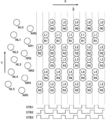
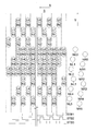
- the wiring 38 is connected to the head drive circuit 51 via the connector 40 or the like, and transmits data or the like serially transferred from the computer 4 to the head drive circuit 51.
- the head drive circuit 51 includes a shift register 52, a latch circuit 53, a level shifter circuit 56, a drive waveform generator 57, and the like.
- the head drive circuit 51 temporarily shifts the data d1, d2,. The data are sequentially stored in the register 52.
- the latch circuit 53 When the data d1, d2,..., Dn are accumulated in the shift register 52, when the latch signal LAT is input to the latch circuit 53, the latch circuit 53 receives the data d1 from the shift register 52 at that timing. , D2,..., Dn, and processing such as changing the order of each data as necessary is appropriately performed. Further, the next series of data is sequentially stored in the empty shift register 52.
- the data d1, d2,..., Dn output from the latch circuit 53 are transmitted to the comparator 54, sequentially output from the comparator 54 in accordance with the strobe clock STBCLK, and data d1, d2 output from the comparator 54. ,..., Dn are sent to the AND circuits 55, respectively.
- the AND circuit 55 when either the data d output from the comparison unit 54 or the strobe pulses STB1, STB2, STB3 is ON, the data d is input from the AND circuit 55 to which the ON strobe pulse STB is input to the level shifter circuit 56. Is sent.
- the strobe pulse STB2 when the strobe pulse STB1 is at a high level, the strobe pulse STB2 is high from the nozzles NR3m and NL3m (see FIG. 3). Ink is ejected from the nozzles NR3m + 1 and NL3m + 1 when the level is high, and from the nozzles NR3m + 2 and NL3m + 2 when the strobe pulse STB3 is at the high level. Yes.
- the strobe pulses STB1, STB2, and STB3 are switched in the order phase or the opposite phase, so that the nozzles NR3m, NR3m + 1, NR3m + 2 and the nozzles NL3m, NL3m + 1, NL3m + of the recording head 5 are switched. 2 is driven three-phase in the order phase or opposite phase.
- the level shifter circuit 56 sends the data d1, d2,..., Dn to the drive waveform generator 57 in accordance with the upper and lower voltages, and the drive waveform generator 57 uses the data d1, d2,. For example, nozzle drive signals D1, D2,..., Dn having drive waveforms as shown in FIG. 7 are generated, and the nozzle drive signals D1, D2,. , Dn are sequentially transmitted.
- each nozzle N of the recording head 5 is driven in three phases, and when the nozzle drive signal D is applied in a state where the high level strobe pulse STB is applied, the nozzle N is illustrated.
- the piezo elements that are not deformed are deformed according to the drive waveform of the nozzle drive signal D, and ink is ejected from the nozzles N, respectively.
- FIG. 8 is a block diagram showing a control configuration of the ink jet recording apparatus according to the present embodiment.
- the ink jet recording apparatus 1 includes a control unit 9.
- the control means 9 can be configured in the computer 4 described above, but can also be configured by a general-purpose computer separate from the computer 4 or a microcomputer having a dedicated processor.
- the control unit 9 controls the operation of each functional unit of the apparatus.
- the control unit 9 drives the scanning drive mechanism 10 to move the carriage 32 (see FIGS. 1 and 2) along the carriage rail 31 in the main scanning direction.
- the driving motor 22 is driven in accordance with the scanning in the main scanning direction X of each recording head 5 that is scanned above the recording medium S as the carriage 32 moves, and the conveying belt is moved.
- the recording medium S is intermittently transported by intermittently moving 23 in the transport direction Z (sub-scanning direction Y).
- control unit 9 appropriately drives a pump 11 provided in the ink supply system so as to supply ink from the ink tank 81 to each recording head 5 via the pipe 34 and the ink supply pipe 36.
- control means 9 is provided with input means (not shown) such as a mouse, a keyboard, and a touch panel, so that the ejection frequency f for each nozzle row of the recording head 5 can be set. Yes.
- control means 9 controls the computer 4 so that each head N corresponding to each nozzle N of each recording head 5 which the head driving circuit 51 is in charge of, as shown in FIG. Data d1, d2,... Are serially transferred at a predetermined timing.
- the control means 9 scans the recording head 5 in the main scanning direction X at a moving speed of L ⁇ f as in the conventional recording method, and the nozzle rows R3m, R3m + 1, R3m + 2 of the recording head 5 and The driving phase of each nozzle N in the nozzle rows L3m, L3m + 1, and L3m + 2 is switched according to the rank phase, or the moving speed of the recording head 5 is doubled, that is, 2 ⁇ L ⁇ f in the main scanning direction X To which the nozzles R3m, R3m + 1, R3m + 2 and the nozzles N of the nozzle rows L3m, L3m + 1, L3m + 2 are switched in the opposite phase. It can be specified via.
- the control unit 9 sets the moving speed in the main scanning direction X of the carriage 32 on which the recording head 5 is mounted to the scanning drive mechanism 10 to L ⁇ f. Further, with respect to the head drive circuit 51, the nozzle rows R3m to R3m + 2 and the nozzle rows L3m to L3m + 2 of the recording head 5 are moved forward with respect to the recording medium S relative to the recording medium 5 (main scanning direction X). The nozzles are set so as to be driven in order from the nozzle row to the rear nozzle row (that is, so as to drive in the order phase).
- the recording head 5 shown in FIG.
- the strobe pulse STB applied to each nozzle N is switched in the order of STB1, STB2, and STB3, and the recording head 5 scans in the direction opposite to the main scanning direction X.
- the strobe pulse STB applied to each nozzle N is switched in the order of STB3 ⁇ STB2 ⁇ STB1.
- the recording head 5 moves and scans in the main scanning direction X at a moving speed of L ⁇ f, and the nozzle rows R3m to R3m + 2 of the recording head 5 and As shown in FIG. 4, ink is ejected from the nozzles NR3m to NR3m + 2 and NL3m to NL3m + 2 of the nozzle array L3m to L3m + 2 at the pixel positions of the recording medium S corresponding to the nozzles N, respectively. Ink is successively ejected to pixels adjacent in the main scanning direction X, and an image is recorded on the recording medium S.
- the control means 9 sets the moving speed in the main scanning direction X of the carriage 32 on which the recording head 5 is mounted to the scanning drive mechanism 10 by 2 ⁇ .
- L ⁇ f, and the nozzle array R3m to R3m + 2 and the nozzle array L3m to L3m + 2 of the recording head 5 with respect to the head drive circuit 51 are moved relative to the recording medium S in the direction of relative movement of the recording head 5 ( It is set so that ejection driving is performed in order from the last nozzle row in the main scanning direction X) to the front nozzle row (that is, ejection driving is performed in reverse phase).
- the nozzle rows R3m to R3m + 2 and the nozzle rows L3m to L3m + 2 of the recording head 5 are driven to discharge in opposite phases
- the recording head 5 shown in FIG. 3 is scanned once in the main scanning direction X
- the strobe pulse STB applied to each nozzle N is switched in the order of STB3 ⁇ STB2 ⁇ STB1
- the recording head 5 is scanned in a direction opposite to the main scanning direction X, for example,
- the strobe pulse STB applied to each nozzle N is switched in the order of STB1, STB2, and STB3.
- the nozzles NR3m, NR3m + 1, and NR3m + 2 of the nozzle rows R3m, R3m + 1, and R3m + 2 of the recording head 5 are respectively shown in FIG.
- Ink is ejected to the corresponding pixel positions of the recording medium S every other pixel in the main scanning direction X.
- each nozzle NR3m, NR3m + 1, NR3m + 2 has the interval q between the adjacent nozzles N in the sub-scanning direction Y set to twice the pixel pitch L, the sub-scanning direction Y
- ink is ejected every other pixel.
- ink is ejected from the nozzles NL3m, NL3m + 1, and NL3m + 2 of the nozzle rows L3m, L3m + 1, and L3m + 2 of the recording head 5, but the nozzles NL3m, NL3m + 1, and NL3m + 2 are also ejected.
- nozzles NL3m, NL3m + 1, and NL3m + 2 are also ejected.
- ink is ejected to pixel positions adjacent to the sub-scanning direction Y of the pixel positions from which ink was ejected from the nozzles NR3m, NR3m + 1, and NR3m + 2.
- the recording head 5 is moved in the main scanning direction X without transporting the recording medium S in the transport direction Z (sub-scanning direction Y).
- the ink ejected from each nozzle N is the same position in the sub-scanning direction on the recording medium S as in the case shown in FIG. Discharged.
- the nozzle N extends in the main scanning direction X at a position corresponding to the nozzle N in the image recorded on the recording medium S. It will be in the state where the line-like pattern entered.
- the control means 9 drives the drive motor 22 to move the recording medium S in the transport direction Z (sub-scanning direction Y).
- the ink is landed on the recording medium S by the previous scanning of the recording head 5 in the next scanning of the recording head 5 in the opposite direction of the main scanning direction X.
- Ink is ejected from each nozzle to a pixel position other than the pixel position.
- the control unit 9 moves the recording medium S in the sub-scanning direction.
- Y for example, upward direction in the figure
- the pixel pitch is moved by, for example, a distance of 6 times, and stopped, and in the next scan in the direction opposite to the main scanning direction X of the recording head 5, as shown in FIG.
- Ink is ejected from each nozzle to a pixel position adjacent to the pixel position where ink has landed on the recording medium S in the previous scan of the head 5. Note that how many pixel pitches the recording medium S is moved in the sub-scanning direction Y is appropriately set.
- W1 is the interval in the sub-scanning direction Y between adjacent nozzles N in the recording head, and specifically, for example, the interval between NL0 and NR0.
- W1 number of nozzles ⁇ W2 / W3, where W3 is the number of multipasses.
- W2 is 1 times the pixel pitch
- the number of nozzles is 12, and the number of multipasses W3 is 2, as will be described later. Therefore, the movement distance W1 is equal to the pixel pitch. 6 times.
- the ink ejected from the same nozzle N of the recording head 5 does not land at least on adjacent pixel positions on the recording medium S. For this reason, even when there is a nozzle N that does not normally eject ink due to a lack of nozzle in a part of the nozzle N, as shown in FIG. Since the ink ejected from another normal nozzle N is landed and filled in the pixel position adjacent to the pixel position, the portion where the ink is not ejected in the image recorded on the recording medium S is in the main scanning direction X. It is prevented that the images are continuously arranged, and a phenomenon in which a streak-like pattern appears in the image is avoided, so that deterioration in image quality can be suppressed.
- the recording head 5 is scanned in the main scanning direction X at a moving speed of 2 ⁇ L ⁇ f, and the nozzle arrays R3m to R3m + 2 and the nozzle arrays L3m to L3m + of the recording head 5 are scanned.
- the nozzles 2 are ejected in the opposite phase, the pixel positions of the ink ejected from the nozzles N of the recording head 5 and landed on the recording medium S are scattered pixel positions as shown in FIGS. 10 and 11, for example. become. Therefore, it is necessary to appropriately rearrange the data arrangement order when serially transferring each data corresponding to each nozzle N of the recording head 5 from the computer 4 to the head driving circuit 51.
- the image recorded on the recording medium S is a pixel row represented by inks L3, L0, L3, L0, L3, L0,... Extending in the main scanning direction X.
- Each pixel position of an image recorded on the recording medium S is represented by coordinates (x, y).
- data corresponding to a nozzle N that ejects ink at a pixel position represented by coordinates (x, y) is represented by d (x, y).
- the computer 4 stores, in the RAM, each data d (x, y) obtained by converting image data of an image to be recorded on the recording medium S input from an external device (not shown) into a form corresponding to each nozzle N of the recording head 5. expand.
- each data d (x, y) obtained by converting image data of an image to be recorded on the recording medium S input from an external device (not shown) into a form corresponding to each nozzle N of the recording head 5. expand.
- the computer 4 applies 0, 0, 0, respectively to the nozzles NR0, NR1, NR2, NR3, NR4, NR5,.
- Each data of d (0, 1), 0, 0,.
- the computer 4 sequentially associates each data of 0, 0, 0, d (0, 0), 0, 0,... With the nozzles NL0, NL1, NL2, NL3, NL4, NL5,. Arrange. Each data is concatenated and arranged in the form of 0, 0, 0, d (0, 1), 0, 0,..., 0, 0, 0, d (0, 0), 0, 0,. . Note that data having a value of 0 is so-called dummy data and represents that ink is not ejected.
- the ink ejected from the nozzles NR0, NR1,..., NL0, NL1,... In the next ejection cycle lands on the pixel positions of R0, R1,..., L0, L1,. 4 represents nozzles NR0, NR1, NR2, NR3, NR4, NR5,..., 0, 0, 0, d (2, 1), d (1, 3), d (0, 5),.
- ... Are sequentially associated and connected.
- the computer 4 stores data d (x, y) corresponding to each pixel position of the recording medium S on which ink ejected from the nozzles NR0, NR1,..., NL0, NL1,. ), Or when there is no data at the corresponding pixel position, each data is arranged in association with dummy data 0, a data string in an appropriate arrangement order is created, and serially transferred to the head drive circuit 51.
- the creation of the data string may be performed in advance before the recording operation is started, or may be configured to be performed in parallel with the recording operation.
- control means 9 and the processing in the computer 4 as described above are not processing specific to the recording head 5 shown in FIG. 3, but a general recording head as shown in FIG. The same can be done when H is used.
- the recording heads 5 and H are provided in the serial head type ink jet recording apparatus using the recording head 5 and the recording head H in which the nozzles N are staggered.
- the nozzles of the recording head 5 and H are moved by scanning at a moving speed (2 ⁇ L ⁇ f) that is twice the conventional moving speed (L ⁇ f).
- the ejection drive is performed sequentially from the last nozzle row in the relative movement direction (main scanning direction X) to the front nozzle row. That is, ejection driving is performed in the opposite phase.
- the recording medium S is moved by a predetermined distance of the pixel pitch L in the sub-scanning direction Y with respect to the recording heads 5 and H. Then, the next scanning is performed, and the ink is ejected from each nozzle N to a pixel position other than the pixel position where the ink has landed on the recording medium S in the previous scanning of the recording heads 5 and H.
- the inkjet recording apparatus described in Patent Document 2 is used.
- an image can be recorded on the recording medium S by one scan (so-called one pass) of the recording heads 5 and H, but the book shown in FIG.
- two scans in order to record an image on the recording medium S, two scans (so-called two passes) of the recording heads 5 and H are required.
- the moving speed of the recording heads 5 and H in the main scanning direction X is twice the conventional moving speed, the time required for image recording is not much different from that in the conventional recording method. That is, according to the present invention, it is possible to avoid the streak-like pattern mixing phenomenon in the image, which could not be avoided by the conventional recording method, in the same recording time as that of the conventional recording method.
- the interval between the corresponding nozzle rows on the left and right that is, the interval between the nozzle row R3m and the nozzle row L3m is set to 1.44 mm.
- this interval corresponds to about 20.4 pixels.
- the discharge timings of the nozzle rows R3m to R3m + 2 and the nozzle rows L3m to L3m + 2 are set.
- ink is ejected from each nozzle N at independent ejection timings without synchronizing the ejection timings of the nozzle rows R3m to R3m + 2 and the nozzle rows L3m to L3m + 2. It can be configured as follows.
- the nozzle rows R3m to R3m + 2 and the nozzle rows L3m to L3m + 2 may not be configured to be driven to discharge at independent discharge timings.
- the ink discharged from each nozzle N of the nozzle rows R3m to R3m + 2 is adjusted by adjusting the discharge frequency (that is, the discharge frequency for each nozzle N) f for each nozzle row of the recording head 5.
- the landing positions on the recording medium S of the ink ejected from the nozzles N of the nozzle rows L3m to L3m + 2 can be aligned in the sub-scanning direction Y.
- the moving speed (2 ⁇ L ⁇ f) of the recording head 5 also changes in accordance with the change in the ejection frequency f.
- the recording head 5 (see FIG. 3) is driven for each driving phase consisting of three phases, and a plurality of nozzles N are staggered in the main scanning direction X at L / 3 intervals (L is a pixel pitch).
- L is a pixel pitch
- two nozzle groups each having three columns are arranged in parallel in the main scanning direction X of the recording head 5 in the same manner as in the first embodiment, and the nozzle N is 256 for each of the left and right groups.
- the recording head 5 is used to record an image on the recording medium S with a resolution of 720 dpi, that is, a resolution twice that of the first embodiment. It is like that.
- the pixel pitch L is 35.3 ⁇ m
- the interval p between the three right and left nozzle columns is set to 1/3 of 1/3 ⁇ m.
- the interval between the corresponding nozzle rows on the left and right that is, the interval between the nozzle row R3m and the nozzle row L3m is 1.44 mm
- the ejection frequency for each nozzle row (that is, the ejection frequency for each nozzle N) f is
- the point set to about 6.7 kHz is the same as that of the first embodiment.
- the interval q in the sub-scanning direction Y between adjacent nozzles N in the same nozzle row set is set to four times the pixel pitch L, and the left and right nozzle rows In the set, the nozzles N are provided with a shift of 2 pixel pitches L in the sub-scanning direction Y. This is also different from the first embodiment.
- the recording head 5 is moved and scanned in the main scanning direction X at a moving speed of L ⁇ f, and the nozzles NR3m, NR3m + 1, NR3m + 2 and the nozzles NL3m, NL3m + of the recording head 5 of this embodiment. 1 and NL3m + 2 are ejected in the order phase as shown in FIG. 25, and then ejected in the conventional three-phase drive as shown in FIG. 25, the main scanning direction of the recording head 5 as shown in FIG.
- Ink discharged from the nozzles N of the nozzles NR3m to NR3m + 2 and the nozzles NL3m to NL3m + 2 in one scan to X is landed every other pixel in the sub-scanning direction Y.
- the recording head 5 when the recording head 5 is driven to discharge by the conventional three-phase driving as described above, the recording head 5 is scanned twice (that is, in two passes). ) Ink is landed on each pixel of the recording medium S to record an image on the recording medium S.
- the control means 9 determines the moving speed in the main scanning direction X of the carriage 32 on which the recording head 5 is mounted with respect to the scanning drive mechanism 10.
- 2 ⁇ L ⁇ f is set, and the nozzle array R3m to R3m + 2 and the nozzle array L3m to L3m + 2 of the recording head 5 are moved relative to the recording medium S with respect to the head driving circuit 51. It is set so that ejection driving is performed in order from the last nozzle row in the direction (main scanning direction X) to the front nozzle row (that is, ejection driving is performed in reverse phase).
- the recording head 5 moves at a moving speed of 2 ⁇ L ⁇ f in the main scanning direction X.
- the nozzles NR3m, NR3m + 1, NR3m + 2 of the nozzle rows R3m, R3m + 1, R3m + 2 of the recording head 5 respectively scan the corresponding recording medium S as shown in FIG. Ink is ejected at every other pixel position in the main scanning direction X.
- each nozzle NR3m, NR3m + 1, and NR3m + 2 has an interval q in the sub-scanning direction Y between adjacent nozzles N set to four times the pixel pitch L.
- ink is ejected every three pixels.
- ink is ejected from the nozzles NL3m, NL3m + 1, and NL3m + 2 of the nozzle rows L3m, L3m + 1, and L3m + 2 of the recording head 5, but the nozzles NL3m, NL3m + 1, and NL3m + 2 are also ejected.
- nozzles NL3m, NL3m + 1, and NL3m + 2 are also ejected.
- control unit 9 drives the drive motor 22 to move the recording medium S in the transport direction Z (sub-scanning direction Y) when the scanning of the recording head 5 in the main scanning direction X is completed. ) Is moved by a predetermined distance of the pixel pitch and stopped, and in the next scan in the direction opposite to the main scanning direction X of the recording head 5, the ink on the recording medium S is scanned by the previous scanning of the recording head 5. Ink is ejected from each nozzle to a pixel position other than the landed pixel position.
- the control unit 9 moves the recording medium S in the sub-scanning direction.
- Y for example, the upward direction in the figure
- the pixel pitch is moved by a distance of, for example, 13 times and stopped, and in the next scan in the direction opposite to the main scanning direction X of the recording head 5, as shown in FIG.
- Ink is ejected from each nozzle to the pixel position at the lower right in the figure of the pixel position where the ink has landed on the recording medium S in the previous scan of the head 5.
- W2 is twice the pixel pitch
- W2 is greater than or equal to twice the pixel pitch
- the ink is ejected from each nozzle to the lower right pixel position in the drawing of the pixel position where the ink has landed on the recording medium S in the previous scan. Is 13 times the pixel pitch.
- the control unit 9 again moves the recording medium S by a distance of 11 times the pixel pitch in the sub-scanning direction Y (for example, the upward direction in the figure).
- the third scan of the recording head 5 is performed by moving and stopping, and in the third scanning of the recording head 5, the pixel position on the right side of the figure where the ink is landed on the recording medium S in the first scan is shown. Ink is ejected from each nozzle to the pixel position.
- the control unit 9 When the third scan of the recording head 5 is completed, the control unit 9 further moves the recording medium S in the sub-scanning direction Y (for example, upward in the figure) by a distance 13 times the pixel pitch and stops it.
- the fourth scan of the recording head 5 is performed, and in the fourth scanning of the recording head 5, each pixel position at the lower side in the figure of the pixel position where the ink is landed on the recording medium S in the first scan is displayed. Ink is ejected from the nozzles.
- the ink ejected from the same nozzle N of the recording head 5 reaches at least the adjacent pixel position on the recording medium S.
- the nozzle N discharges from the nozzle N. Ink ejected from another normal nozzle N is landed and filled in a pixel position adjacent to the pixel position where the ink that should not have landed should be landed.
- the ink ejected from one nozzle N is landed on the recording medium S at intervals rather than every other pixel in the main scanning direction X, and the pixel position of the gap is set to other nozzles. If it is configured to be filled with ink ejected from N, it is possible to make the pixel positions where ink is not ejected from the abnormal nozzle N more diffused in the image, and in the image recorded on the recording medium S. It is possible to more accurately avoid the formation of a streak-like pattern on the surface.
- the control unit 9 causes the ink from the nozzles N to be ejected for each ejection cycle to be performed during one scan of the recording head 5 in the main scanning direction X.
- a discharge cycle for discharging ink from each nozzle N and a discharge cycle for not discharging ink from each nozzle N are provided.
- the recording head 5 (see FIG. 3) used in the inkjet recording apparatus 1 according to the first embodiment is used as the recording head 5 will be described.
- the recording head 5 used in the second embodiment is described. The same applies to the case of using.
- the recording method of the present invention is adopted as in the case of the first and second embodiments. That is, the control means 9 moves the recording head 5 in the main scanning direction X at a moving speed of 2 ⁇ L ⁇ f, and scans the nozzles R3m to R3m + 2 and nozzle rows L3m to L3m + of the recording head 5. 2 is driven to discharge in the opposite phase.
- the recording medium S is moved in the transport direction Z (sub-scanning direction Y) by a distance that is a predetermined multiple of the pixel pitch. This is the same as in the case of the second embodiment.
- control means 9 uses the nozzles for the ink ejection operation from the nozzles N for each ejection cycle to be performed during one scan of the recording head 5 in the main scanning direction X.
- the ejection cycle in which ink is ejected from N and the ejection cycle in which ink is not ejected from each nozzle N can be set to be repeated every one ejection cycle.
- whether or not to provide an ejection cycle that does not eject ink is set according to a user's setting input. Further, how to set the ejection cycle for ejecting ink from each nozzle N and the ejection cycle for not ejecting ink from each nozzle N is appropriately set in advance or upon setting input by the user.
- each nozzle NR3m, NR3m + 1, NR3m + 2 of the nozzle row R3m, R3m + 1, R3m + 2 of the recording head 5 has a first ejection cycle as shown in FIG. Ink is ejected to the corresponding pixel position of the recording medium S, and no ink is ejected in the next ejection cycle.
- ink is ejected every three pixels in the main scanning direction X to the pixel positions of the recording medium S corresponding to the respective nozzles NR3m, NR3m + 1, and NR3m + 2.
- Each nozzle NR3m, NR3m + 1, NR3m + 2 has an interval q in the sub-scanning direction Y between adjacent nozzles N set to twice the pixel pitch L, so every other pixel in the sub-scanning direction Y. Ink is discharged.
- ink is ejected from the nozzles NL3m, NL3m + 1, and NL3m + 2 of the nozzle rows L3m, L3m + 1, and L3m + 2 of the recording head 5, but the nozzles NL3m, NL3m + 1, and NL3m + 2 are also ejected.
- nozzles NL3m, NL3m + 1, and NL3m + 2 are also ejected.
- the nozzles NL3m, NL3m + 1, and NL3m + 2 are adjacent to each other in the sub-scanning direction Y at the pixel position at which ink is ejected from the nozzles NR3m, NR3m + 1, and NR3m + 2. Ink is ejected to the pixel position.
- the control unit 9 drives the drive motor 22 to feed the recording medium S in the transport direction Z (sub-scanning direction Y) to a predetermined pixel pitch.
- the recording head 5 is scanned in the direction opposite to the main scanning direction X by moving it twice the distance.
- the control unit 9 moves the recording medium S in the sub-scanning direction. Move to Y (for example, upward in the figure) by a distance of, for example, 6 times the pixel pitch and stop.
- W2 is 1 times the pixel pitch
- the number of nozzles is 24, and the number of multipasses W3 described later is 4, so the moving distance W1 is 6 times the pixel pitch. It is said.
- the ejection cycle in which ink is ejected from each nozzle N and the ejection cycle in which ink is not ejected from each nozzle N are repeated for each ejection cycle.
- ink is ejected from each nozzle to a pixel position adjacent to the pixel position where ink has landed on the recording medium S in the previous scan of the recording head 5.
- the image recording on the recording medium S is not completed by two scans of the recording head 5 (ie, two passes). Therefore, when the second scanning of the recording head 5 in the main scanning direction X is completed, the control unit 9 further moves the recording medium S in the sub-scanning direction Y (for example, the upward direction in the drawing) by a distance of, for example, 6 times the pixel pitch. Just move and stop.
- the third scanning of the recording head 5 in the main scanning direction X is performed to eject ink from each nozzle N to the adjacent pixel position, and the third scanning of the recording head 5 in the main scanning direction X is completed.
- the recording medium S is moved in the sub-scanning direction Y (for example, upward in the drawing) by a distance of, for example, six times the pixel pitch and stopped, and the fourth scanning of the recording head 5 in the main scanning direction X is performed. Ink is ejected from each nozzle N to adjacent pixel positions.
- the ink is landed on each pixel of the recording medium S by four scans of the recording head 5 (that is, in four passes), and an image is formed on the recording medium S. It becomes possible to record.
- the ink ejected from one nozzle N is landed on the recording medium S with an interval larger than one pixel in the main scanning direction X, and the pixel position of the gap portion is set to a plurality of other nozzles N. It is possible to fill with a plurality of inks ejected from the ink. For example, when ink is ejected as shown in FIGS. 21 and 22, the pixel position that should be ejected from the nozzle N that does not eject ink normally due to the occurrence of nozzle shortage is indicated by a cross. As shown in FIG. 23, there are pixel positions where ink is not ejected every three pixels.
- the pixel position where ink is not ejected from the abnormal nozzle N A plurality of pixel positions in a portion between are landed and filled with a plurality of inks ejected from another plurality of normal nozzles N. Therefore, pixel positions where ink is not ejected are sparsely diffused in the image, and it is possible to more accurately avoid the formation of a streak pattern in the image recorded on the recording medium S.
Landscapes
- Engineering & Computer Science (AREA)
- Quality & Reliability (AREA)
- Ink Jet (AREA)
Priority Applications (3)
| Application Number | Priority Date | Filing Date | Title |
|---|---|---|---|
| JP2011500581A JP5482782B2 (ja) | 2009-02-20 | 2010-02-12 | インクジェット記録装置 |
| EP10743692.5A EP2399746B1 (de) | 2009-02-20 | 2010-02-12 | Tintenstrahlaufzeichnungsvorrichtung |
| US13/201,884 US8469473B2 (en) | 2009-02-20 | 2010-02-12 | Inkjet recording apparatus |
Applications Claiming Priority (2)
| Application Number | Priority Date | Filing Date | Title |
|---|---|---|---|
| JP2009037742 | 2009-02-20 | ||
| JP2009-037742 | 2009-02-20 |
Publications (1)
| Publication Number | Publication Date |
|---|---|
| WO2010095565A1 true WO2010095565A1 (ja) | 2010-08-26 |
Family
ID=42633848
Family Applications (1)
| Application Number | Title | Priority Date | Filing Date |
|---|---|---|---|
| PCT/JP2010/052044 Ceased WO2010095565A1 (ja) | 2009-02-20 | 2010-02-12 | インクジェット記録装置 |
Country Status (4)
| Country | Link |
|---|---|
| US (1) | US8469473B2 (de) |
| EP (1) | EP2399746B1 (de) |
| JP (1) | JP5482782B2 (de) |
| WO (1) | WO2010095565A1 (de) |
Cited By (1)
| Publication number | Priority date | Publication date | Assignee | Title |
|---|---|---|---|---|
| CN105383171A (zh) * | 2014-08-29 | 2016-03-09 | 佳能株式会社 | 液体喷出设备和液体喷出头 |
Families Citing this family (2)
| Publication number | Priority date | Publication date | Assignee | Title |
|---|---|---|---|---|
| JP7350457B2 (ja) * | 2020-07-20 | 2023-09-26 | 株式会社ミマキエンジニアリング | 印刷装置、及び印刷方法 |
| CN115989090B (zh) * | 2020-09-03 | 2023-12-15 | 柯尼卡美能达株式会社 | 图案形成方法以及喷墨印刷装置 |
Citations (3)
| Publication number | Priority date | Publication date | Assignee | Title |
|---|---|---|---|---|
| JPH05338210A (ja) * | 1992-06-11 | 1993-12-21 | Olympus Optical Co Ltd | マルチヘッドプリンタ |
| JP2006051794A (ja) * | 2004-07-14 | 2006-02-23 | Konica Minolta Medical & Graphic Inc | インクジェット記録装置及びインクジェット記録方法 |
| JP2008230200A (ja) * | 2007-03-23 | 2008-10-02 | Konica Minolta Holdings Inc | インクジェット記録装置 |
Family Cites Families (2)
| Publication number | Priority date | Publication date | Assignee | Title |
|---|---|---|---|---|
| JP4146208B2 (ja) * | 2002-10-21 | 2008-09-10 | エスアイアイ・プリンテック株式会社 | インクジェット式記録装置及びインクジェット式記録方法 |
| JP2007234718A (ja) | 2006-02-28 | 2007-09-13 | Matsushita Electric Ind Co Ltd | 半導体集積回路装置 |
-
2010
- 2010-02-12 EP EP10743692.5A patent/EP2399746B1/de active Active
- 2010-02-12 JP JP2011500581A patent/JP5482782B2/ja active Active
- 2010-02-12 WO PCT/JP2010/052044 patent/WO2010095565A1/ja not_active Ceased
- 2010-02-12 US US13/201,884 patent/US8469473B2/en not_active Expired - Fee Related
Patent Citations (3)
| Publication number | Priority date | Publication date | Assignee | Title |
|---|---|---|---|---|
| JPH05338210A (ja) * | 1992-06-11 | 1993-12-21 | Olympus Optical Co Ltd | マルチヘッドプリンタ |
| JP2006051794A (ja) * | 2004-07-14 | 2006-02-23 | Konica Minolta Medical & Graphic Inc | インクジェット記録装置及びインクジェット記録方法 |
| JP2008230200A (ja) * | 2007-03-23 | 2008-10-02 | Konica Minolta Holdings Inc | インクジェット記録装置 |
Cited By (1)
| Publication number | Priority date | Publication date | Assignee | Title |
|---|---|---|---|---|
| CN105383171A (zh) * | 2014-08-29 | 2016-03-09 | 佳能株式会社 | 液体喷出设备和液体喷出头 |
Also Published As
| Publication number | Publication date |
|---|---|
| EP2399746A1 (de) | 2011-12-28 |
| JP5482782B2 (ja) | 2014-05-07 |
| US20110298852A1 (en) | 2011-12-08 |
| US8469473B2 (en) | 2013-06-25 |
| EP2399746A4 (de) | 2013-08-07 |
| JPWO2010095565A1 (ja) | 2012-08-23 |
| EP2399746B1 (de) | 2015-09-23 |
Similar Documents
| Publication | Publication Date | Title |
|---|---|---|
| KR100239604B1 (ko) | 다중 소자 프린터 및 이 프린터의 조정 방법 | |
| CN101186147B (zh) | 打印装置和打印方法 | |
| JP2012040806A (ja) | 記録装置および記録方法 | |
| JP2011025609A (ja) | 流体噴射装置、及び、流体噴射方法 | |
| JP5636649B2 (ja) | 流体噴射装置、及び、流体噴射方法 | |
| JP5339801B2 (ja) | 画像処理装置および画像処理方法 | |
| CN107428161A (zh) | 喷墨记录装置及喷墨记录方法 | |
| US6814425B2 (en) | Droplet placement onto surfaces | |
| JP4513802B2 (ja) | 印刷装置 | |
| JP5482782B2 (ja) | インクジェット記録装置 | |
| CN101357542A (zh) | 喷墨式图像形成装置及其控制方法 | |
| US7118191B2 (en) | Apparatus and method for ink jet printing using variable interlacing | |
| TWI435809B (zh) | Printing apparatus and printing method | |
| JP2002166535A (ja) | インクジェット記録装置、及びインクジェット記録方法 | |
| JP2021091221A (ja) | 相補的で不規則な境界を有するスプライシングストリップの印刷方法 | |
| JPH0970959A (ja) | 記録装置 | |
| JP5195525B2 (ja) | 画像記録装置、画像記録装置における駆動位相の調整方法及び画像記録装置における位置調整チャートの出力方法 | |
| JP2011025608A (ja) | 流体噴射装置、及び、流体噴射方法 | |
| JP5898423B2 (ja) | インクジェット記録装置および記録方法 | |
| JP4211280B2 (ja) | 複数の印刷ヘッドを用いる印刷 | |
| JP7755641B2 (ja) | シングルパスモノクロ印刷を高速に行う方法及びプリントチップ | |
| US7618113B2 (en) | Liquid discharge apparatus and liquid discharge method | |
| JP2008155378A (ja) | 印刷方法、及び、印刷装置 | |
| JP5560679B2 (ja) | 流体噴射装置、及び、流体噴射方法 | |
| JP5250839B2 (ja) | 画像記録装置、画像記録装置における駆動位相の調整方法及び画像記録装置における位置調整チャートの出力方法 |
Legal Events
| Date | Code | Title | Description |
|---|---|---|---|
| 121 | Ep: the epo has been informed by wipo that ep was designated in this application |
Ref document number: 10743692 Country of ref document: EP Kind code of ref document: A1 |
|
| WWE | Wipo information: entry into national phase |
Ref document number: 2011500581 Country of ref document: JP |
|
| WWE | Wipo information: entry into national phase |
Ref document number: 2010743692 Country of ref document: EP |
|
| WWE | Wipo information: entry into national phase |
Ref document number: 13201884 Country of ref document: US |
|
| NENP | Non-entry into the national phase |
Ref country code: DE |