EP2399746B1 - Tintenstrahlaufzeichnungsvorrichtung - Google Patents
Tintenstrahlaufzeichnungsvorrichtung Download PDFInfo
- Publication number
- EP2399746B1 EP2399746B1 EP10743692.5A EP10743692A EP2399746B1 EP 2399746 B1 EP2399746 B1 EP 2399746B1 EP 10743692 A EP10743692 A EP 10743692A EP 2399746 B1 EP2399746 B1 EP 2399746B1
- Authority
- EP
- European Patent Office
- Prior art keywords
- scanning direction
- nozzle
- ink
- recording head
- nozzles
- Prior art date
- Legal status (The legal status is an assumption and is not a legal conclusion. Google has not performed a legal analysis and makes no representation as to the accuracy of the status listed.)
- Active
Links
Images


Classifications
-
- B—PERFORMING OPERATIONS; TRANSPORTING
- B41—PRINTING; LINING MACHINES; TYPEWRITERS; STAMPS
- B41J—TYPEWRITERS; SELECTIVE PRINTING MECHANISMS, i.e. MECHANISMS PRINTING OTHERWISE THAN FROM A FORME; CORRECTION OF TYPOGRAPHICAL ERRORS
- B41J2/00—Typewriters or selective printing mechanisms characterised by the printing or marking process for which they are designed
- B41J2/005—Typewriters or selective printing mechanisms characterised by the printing or marking process for which they are designed characterised by bringing liquid or particles selectively into contact with a printing material
- B41J2/01—Ink jet
- B41J2/21—Ink jet for multi-colour printing
- B41J2/2132—Print quality control characterised by dot disposition, e.g. for reducing white stripes or banding
-
- B—PERFORMING OPERATIONS; TRANSPORTING
- B41—PRINTING; LINING MACHINES; TYPEWRITERS; STAMPS
- B41J—TYPEWRITERS; SELECTIVE PRINTING MECHANISMS, i.e. MECHANISMS PRINTING OTHERWISE THAN FROM A FORME; CORRECTION OF TYPOGRAPHICAL ERRORS
- B41J2/00—Typewriters or selective printing mechanisms characterised by the printing or marking process for which they are designed
- B41J2/005—Typewriters or selective printing mechanisms characterised by the printing or marking process for which they are designed characterised by bringing liquid or particles selectively into contact with a printing material
- B41J2/01—Ink jet
- B41J2/135—Nozzles
- B41J2/145—Arrangement thereof
Definitions
- the present invention relates to an inkjet recording apparatus, and in particular, to an inkjet recording apparatus using a recording head having nozzles in a staggered arrangement which are driven by multiple-phase.
- an image forming apparatus capable of recording an image on a substrate (hereinafter called a recording medium) having a low ink absorbability such as resin film besides ordinary substrates such as a paper and a texture
- a recording medium having a low ink absorbability such as resin film besides ordinary substrates such as a paper and a texture
- an inkjet recording apparatus which lands ink ejected from a nozzle disposed at an end surface (a so-called nozzle surface) of a recording head on the substrate, and at the present day, a technology of the apparatus is applied to various technical fields.
- a recording head in which nozzles are arranged in rows in parallel on the nozzle surface is often used.
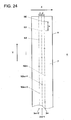
- a recording head having three nozzles rows 3m, 3m+1 and 3m+2 in which a plurality of nozzles N are arranged in a staggered form with a predetermined interval in a main scanning direction X indicated by an arrow X in the figure for example, refer to Patent Document 1).
- Fig. 24 shows, there has been often used a recording head having three nozzles rows 3m, 3m+1 and 3m+2 in which a plurality of nozzles N are arranged in a staggered form with a predetermined interval in a main scanning direction X indicated by an arrow X in the figure (for example, refer to Patent Document 1).
- nozzles are formed on a nozzle surface P, wherein the nozzle surface P represents a side, which is facing the recording medium S, of the recording head.
- a nozzle interval p between each of rows of nozzles N 3m, N3m+1 and N3m+2 is configured to be 1/3 or 2/3 of the pixel pitch L, namely L/3 or 2L/3.
- an interval q between each adjacent nozzle N in the sub-scanning direction Y is usually configured to be equal to the pixel pitch L.
- each nozzle N3m belongs to the same row is collectively called nozzle row 3m.
- the a nozzle row configured with each nozzle N3m+1 denoted by the nozzle number 3m+1 is called a nozzle row 3m+1
- the a nozzle row configured with each nozzle N 3m+2 denoted by the nozzle number 3m+2 is called a nozzle row 3m+2.
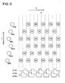
- the nozzles N in the staggered arrangement are usually driven by a multi-phase and in the recording head H in which the nozzles N are disposed in the staggered arrangement by three nozzles as Fig. 24 shows, each of nozzles N3m, N 3m+1 and N 3m+2 is driven by three-phase.
- the three-phase drive of each of nozzles N 3m, N 3m+1, N m+2 having been conducted conventionally is conducted as follow.
- a strobe pulse STB1 is applied to each of the nozzles N3m in the nozzle row 3m, and in this state by applying an unillustrated drive pulse, ink is ejected to the recording medium S from each of the nozzles N3m in the nozzle row 3m to which the strobe pulse STB1 is applied.
- the strobe pulse is changed from STB1 to STB2 and applied to each of nozzles N3m+1 in the nozzle row 3m+1.
- the ink is ejected to the recording medium S from each of the nozzles N 3m +1 in the nozzle row 3m+1 to which the strobe pulse STB2 is applied.
- the strobe pulse is changed from STB 2 to STB 3 and applied to each of nozzles N3m+2 in the nozzle row 3m+2.
- ink is ejected to the recording medium S from each of the nozzles N3m +2 in the nozzle row 3m+2.
- the ink ejected from each of nozzles N3m+2 lands on an adjacent position in the sub-scanning direction Y on which the ink ejected from each of nozzles N3m+1 has been landed.
- the ink ejected from each of nozzles N3m to N2m+2 can be landed on a line which extends in the sub-scanning direction on the recording medium S.
- a method to change the phases to drive from the nozzle N3m in a front section to the nozzle N3m+1 on a rear side sequentially in the moving direction of the recording head H in the main scanning direction X is called normal phase.
- each of the nozzles N3m in the nozzle row 3m comes to a position which is distant the pixel pitch L from the position where the ink is first ejected.
- the drive pulse in a state where the strobe pulse is changed from STB3 to STB1 and is applied to each of the nozzles N3m in the nozzle row 3m
- the ink is ejected from each of the nozzles N3m in the nozzle row 3m to a position displaced by the pixel pitch L in the main scanning direction X from a position where the ink has been first ejected. Therefore, the ink lands on an adjacent position to the position where the ink has been first ejected from each nozzle N3m in the nozzle row 3m.
- the ink is landed on the line extending in the sub-scanning direction, and the ink is also landed on another line in an adjacent position to the above line of the ink extending in the main scanning direction X on the recording medium S.
- the ink lands on each pixel on the recording medium S so that an image is recorded on the recording medium S.
- Figs. 24 and 25 show, in case the recording head H moves to a left side in the figure, by changing the strobe pulse from STB1 to STB2 and to STB3 sequentially, the nozzle N to eject ink is changed from the nozzle N3m in the front section in the moving direction of the recording head H to the nozzle N3m+1 and to the nozzle N3m+2 on the rear side, however in case the image is recorded while the recording head H is being moved to the left side in the figure, the nozzle N in the front section in the moving direction of the recording head H is changed to the nozzle N3m+2, thus the strobe pulse is changed from STB3 to STB2 and to STB 1 sequentially so that the nozzle N to eject ink is changed from the nozzle N3m+2 in the front side in the moving direction of the recording head H to the nozzle N3m+1 and to N3m on the rear side.
- a so-called reverse phase is suggested that is when the recording head H is moved to a right side in the figure, instead of changing the nozzles N to eject ink from the nozzle N3m in the front section in moving direction of the recording head H in the main scanning direction to the nozzle N3m+1 and to N3m+2 on the rear side, the driving phase is changed so that the nozzle N is changed from the nozzle N3m+2 on the rear side in the moving direction of the recording head H in the main scanning direction X to the nozzle N3m+1 and to N3m in the front section.
- Fig. 27 shows, by increasing the moving speed of the recording head H in the main scanning direction X two times, the same nozzle N ejects ink at every other pixel.
- Fig. 28 shows, by disposing another recording head H' having nozzles M in the staggered arrangement in parallel to the recording head H in the main scanning direction X, or as Fig. 29 shows, by further disposing nozzles M in the staggered arrangement in parallel to the nozzles N in the main scanning direction X on the recording head H having the nozzles N in the staggered arrangement, and by driving the nozzles N as well as the nozzles M with an reverse phase for ejection, as Fig. 30 shows, the ink is ejected from the nozzles M and landed on gap sections to which the ink has been ejected from the nozzle N on the recording medium S so as to form the image on the recording medium S.
- the ink ejected from the normal nozzle M lands and fills a pixel position adjacent to the position on which the ink has not been ejected is supposed to land. Therefore, as Fig. 26 shows, it is prohibited that the portions where the ink is not ejected line up continuously in the main scanning direction X in the recorded image on the recording medium S, and a phenomenon that the streak-like pattern appears in the image can be prohibited. Thus deterioration of image quality can be suppressed.
- the pulse width (time interval of high level of the pulse) of the strobe pulses STB1 to STB3 are described as if the pulse width is two times of the pulse with of the strobe pulses STB1 to STB3 shown in Fig. 25 . This is because the moving speed of the recording head D was increased two times and the pulse widths of the strobe pulses STB1 to STB3 themselves remain unchanged.
- JP 2004-142100 discloses a related inkjet recording apparatus.
- the inkjet recording apparatus employs a line head method, and it is based the premise that the image is recorded by ejecting ink onto all the pixels on the recording medium while the recording medium moves one time relatively to the recording head. Namely, the image will have to be recorded through a so-called one pass.
- the ink is ejected from the nozzle N and lands onto every other pixels.
- the one more recording head having nozzles M in the staggered arrangement is further disposed in parallel on the recording head H in the main scanning direction X or the nozzles M in the staggered arrangement are disposed in parallel to the nozzles N in the main scanning direction X on the recording head H having the nozzles N in the staggered arrangement.
- the above problems are caused by a restriction that the image is recorded through one pass since the inkjet recording apparatus employs a line head method, and in case of the serial head method inkjet recording apparatus the above problems do not occur.
- the inkjet recording apparatus of the serial head method it can be configured that the image is recorded by ejecting ink onto all the pixels on the recording medium through a plurality of passes, namely while the recording head and the recording medium relatively move several times. Therefore, it is not necessary to dispose the new recording head or to manufacture the exclusive recording head, and the existing recording head can be utilize.
- the present invention has one aspect to solve the above problem and an object of the present invention is to provide an inkjet recording apparatus capable of improving the image quality of the recorded image without creating the streak-like pattern in the image on the recorded apparatus in the serial had method inkjet recording apparatus using the recording head in which the nozzles are disposed in the staggered arrangement.
- the recording method of the present invention though the image can be recorded on the recording medium through one scan (so-called one pass) by the head, however in the recording method of the present invention, two scans (so-called two passes) by the recording head is necessary to record the image on the recording medium.
- the moving speed of the recording head in the main scanning direction is two times of that of the conventional method, there is not much change in the time required for image recording compared to the conventional recording method. Namely, according to the invention of claim 1, the phenomenon that the streak-like patter is mixed in the image can be prohibited within almost the same recording time as that of the conventional recording method, wherein the phenomenon was unable to be prohibited in the conventional method.
- the same effect as that in the aforesaid invention can be also realized in case that there is used the recording head having two nozzle row sets configured with three rows disposed in parallel in the main scanning direction, wherein an interval between the adjacent nozzles in the sub-scanning direction in the same nozzle row set is set two times of the pixel pitch, and the nozzles in the nozzle rows of one nozzle row set are offset by the pitch of one pixel with respect to the nozzles in the nozzles rows of other nozzle row set in the sub-scanning direction.
- the same effect as that in the aforesaid invention can be also realized, in case that there is used the recording head having two nozzle row sets configured with three rows disposed in parallel in the main scanning direction, wherein a distance between the adjacent nozzles in the sub-scanning direction in the same nozzle row set is set four times of the pixel pitch, and the nozzles in one nozzle row set are offset by two pixel pitches with respect to the nozzles in another nozzle row set in the sub-scanning direction.
- An inkjet recording apparatus 1 related to a first embodiment is mainly configured with a conveyance section 2, a main scanning section 3, and a computer 4 as Fig. 1 shows. Also, Fig. 2 is a magnified view of a carriage section in an internal structure of the main scanning section 3 including a recording head 5 to be described.
- a drive roller 21 extending in the main scanning direction X and an unillustrated driven roller are supported rotatably, and at one end side of the drive roller 21 a drive motor 22 to drive and rotate the drive roller 21 is disposed.
- a conveyance belt 23 in an endless shape is suspended between the drive roller 21 and the driven roller and the conveyance belt 23 conveys a recording medium S placed on the upper surface thereof in a conveyance direction Z by circling around the drive roller 21 and the driven roller when the drive roller 21 is rotated.
- the drive motor 22 rotates the drive roller 21 by a predetermined amount to convey the recording medium S in the conveyance direction Z by a predetermined distance and stops, then scanning in an opposite direction in the main scanning direction by the recording head 5 starts and finishes, the drive motor 22 rotates the drive roller 21 by the predetermined amount again to convey the recording medium S in the conveyance direction Z by the predetermined distance and stops.
- the above operation is repeated so that the recoding medium S is conveyed via so-called intermittent conveyance.
- the conveyance direction Z of the recording medium S is set to be parallel to the sub-scanning direction Y which is perpendicular to the main scanning direction X.
- the recording medium S can be conveyed on a platen in a shape of a flat plate in the conveyance direction Z (sub-scanning direction) instead of conveying the recording medium S on the conveyance belt S.
- a resin film and metals can be used without being limited as described in the foregoing.
- a main scanning section 3 is disposed above the conveyance belt 23 of the conveyance section 2, a main scanning section 3 is disposed. Inside the main scanning section 3, a carriage rail 31 in a shape a bar extending the main scanning direction X is disposed. On the carriage rail 31, a carriage 32 substantially in a shape of housing is supported so as to be able to reciprocate in the main scanning direction X. The carriage 32 moves in the main scanning direction X along the carriage rail 31 so as to perform scan via a scanning mechanism which includes an unillustrated motor.
- Carriage 32 is equipped with a recording head 5 in which a surface P (hereinafter called nozzle surface P) facing the recording medium S, a plurality of nozzles N to eject ink of each of colors, yellow (Y), magenta (M), cyan (C) and black (K) when recording an image, are disposed.
- Nozzles N on each recording head 5 eject an ink droplet of each color with respect to the recording medium on the conveyance belt 23.
- a configuration of the recording head 5 will be described later.
- a cable pair 33 including unillustrated piping to supply ink to the recording head 5 from an ink tank 81 to be described and unillustrated wiring to propagate electric signals and power to drive the recording head 5.
- an end section of the main scanning section 3 in the main scanning direction X represents a maintenance section 6 to carry out maintenance of the recording head 5.
- another end side of the main scanning section 3 in the main scanning direction X represents a nozzle moisturizing section 7 to moisturize the nozzle surface P of the recording head 5 by a cap in a non-recording operation time so that failures of ink ejection from the nozzles N do not occur due to drying of the nozzles N of the recording head 5 in the non-recording operation time.
- an ink rack provided with the ink tank 81 to reserve ink of each color to be supplied to each recording head 5 is disposed. From each ink tank 81, ink is supplied to each recording head 5 via the aforesaid piping and an unillustrated ink supply pipe.
- the computer 4 for image processing is provided below the main scanning section 3.
- the computer converts image data of an image inputted form an unillustrated external apparatus to be recorded on the recording medium S into data corresponding to each nozzle of the recording head 5. From the computer 4, the data is serially transferred to an unillustrated head drive circuitry to drive the recording head 5 via the aforesaid wiring.
- the computer 4 is configured with a general purpose computer in which an unillustrated CPU (Central Processing Unit), a ROM (Read Only Memory), a RAM (Random Access Memory) and an input and output interface are connected to a bus line.
- an unillustrated CPU Central Processing Unit
- ROM Read Only Memory
- RAM Random Access Memory
- the recoding head 5 it is possible to employ an general recording head H having three nozzle rows 3m, 3m+1 and 3m+2 wherein the plurality of the nozzles N3m, N3m+1 and N3m+2 are disposed in the staggered arrangement with an interval ofL/3 in the main scanning direction X as Fig. 24 shows.
- an existing recording head shown in Fig. 3 is used as the recording head 5.
- the recoding head 5 is driven by each drive phase of a three-phases current, and two sets of nozzle rows, which are configured with three rows having a plurality of the nozzles N disposed in the staggered arrangement with an interval ofL/3 (L is a pixel pitch) in the main scanning direction X, are disposed in parallel in the main scanning direction X of the recording ahead 5.
- the nozzle rows belong to a set on a right side in the figure are denoted as R3m, R3m+1 and R3m+2, and the nozzles belong to the nozzle rows R3m, R3m+1 and R3m+2 are denoted as NR3m, NR3m+1 and NR3m+2, also the nozzle rows belong to a set on a left side in the figure are denoted as L3m, L3m+1 and L3m+2, and the nozzles belong to the nozzle rows L3m, L3m+1 and L3m+2 are denoted as NL3m, NL3m+1 and NL3m+2.
- an even number of 256 nozzles N are formed respective for left and right set, namely a total of 512 nozzles N.
- the image is formed with a resolution of 360 dpi on the recording medium S.
- the interval p among the three nozzle rows on left and right are set at 1/3 of the above pitch which is 23.5 ⁇ m.
- intervals between the left and right nozzle rows corresponding, namely nozzles rows R3m and L3m, R3m+1 and L3m+1, and R3m+2 and L3m+2 are set at 1.44 mm.
- an ejection frequency f (namely an ejection frequency for each nozzle N) of each nozzle row of the recording head 5 in the present embodiment is set appropriately, for example, around 6.7 kHz.
- an interval q between each adjacent nozzle N in the same nozzle row set in the sub-scanning direction Y is set to be two times of the pixel pitch L, namely 141 ⁇ m.
- the nozzles N are displaced by one pixel pitch L in the sub-scanning direction Y.
- ejection drive is performed with three-phase drive, which has been performed conventionally, by moving the recording head 5 at a moving speed ofL x f for scan, and by driving each of the nozzles NR3m, NR 3m+1, and NR3m+2, and NL3m, NL 3m+1 and NL3+2 in the recording head 5 of the present embodiment to eject with normal phase as shown in Fig. 25 (namely, each nozzle row of the recording head 5 is driven to eject from a nozzle row in a front section to a nozzle row on a rear side successively in the relative moving direction (main scanning direction X) of the recording head 5 with respect to the recording medium S), as Fig.
- the recording head 5 of the present embodiment seems to be similar to the recording head H used in the inkjet recording apparatus in Patent Document 2 shown in Fig. 29 , however, different from the recording head H shown in Fig. 29 , the recording head 5 has the same function as that of the recording head H shown in Fig. 24 having three nozzle rows 3m, 3m+1 and 3m+2 in which the plurality of the nozzles N3m, N3m+1 and N3m+2 are disposed in the staggered arrangement with the interval L/3 in the main scanning direction X.
- the recording head 5 of the present invention can record the image on the recording medium S by landing ink on each pixel on the recording medium S through one scan (namely, one pass) in case ejection drive is conducted via three phase drive which has been conventionally carried out.
- Fig. 4 shows, if ejection drive is conducted by three phase drive having been carried out conventionally, as Fig. 26 shows, a streak pattern is created on the recorded image on the recording medium S and the image quality of the recorded image is deteriorated in case a nozzle failure occurs at a particular nozzle N and the particular nozzle N can not eject ink normally, which was described in the foregoing.
- the cable pair 33 is connected at an upper part of the carriage 32 shown by Fig. 2 , as described in the foregoing.
- the pipe 34 included in the cable pair 33 is connected with an ink supply tube 36 via a joint 35.
- the ink supply tubes 36 are connected with respective recording heads 5 which are omitted in Fig.5 , and the ink of each color supplied from an ink tank 81 (refer to Fig. 1 ) is supplied to each recording head 5 via the pipe 34 and the ink supply tube 36.
- the pipes 34 are included in resin tubes 37 by a predetermined number, and the in the cable pair 33, a partition wall is disposed to divide the pipes 34 and the wires 38 so that they do not contact each other.
- wires 38 are connected with the head drive circuitry 51 via a connector 40 so that data transferred serially from the computer 4 is transferred to the head drive circuitry 51.
- the head drive circuitry 51 is configured with a shift register 52, a latch circuit 53, a level shifter circuitry 56, a drive wave forming section 57 and so forth.
- the head drive circuitry 51 temporally stores the data d1, d2 ... in the shift register 52 in accordance with a clock signal CLK.
- the data d1, d2, ... , dn outputted from the latch circuitry 53 is transmitted to a comparison section 54 and outputted from the comparison section 54 in accordance with the strobe clock STBCLK.
- the data d1, d2,..., dn outputted from the outputted from the comparison section 54 is sent to each and-circuit 55.
- the data d is transferred from one and-circuit, where the strobe pulse is ON, to the level shifter circuitry 56.
- the nozzles NR3m, NR3m+1 and NR3m+2, and the nozzles NL3m, NL3m+1 and NL3m+2 of the recording head 5 are three-phase driven with the normal phase or the reverse phase.
- the level shifter circuitry 56 is configured to transmit each items of data d1, d2,...,dn in accordance with up and down of the voltage to the drive wave forming section 57.
- the drive wave forming section 57 creates nozzle drive signals D1, D2,...D3 having, for example, a drive wave shape shown in Fig. 7 based on the data d1, d2,..., dn, and sends each of nozzle drive signals D1, D2,..., Dn sequentially to each nozzle N of the recording head 5 via each output terminal 58.
- each nozzle N of the recording head 5 is three-phase driven, and in a state where a strobe pulse STB of high level is applied, when the aforesaid nozzle drive signal is applied, an unillustrated piezoelectric element of the nozzle N is deformed in accordance with the drive wave shape of the nozzle drive signal D, then ink is ejected from the nozzle N.
- Fig. 8 is a black diagram showing a control configuration of an inkjet recording apparatus related to the present embodiment.
- An inkjet recording apparatus 1 is provided with a control device 9. While the control device 9 can be configured in the computer 4 described in the forgoing, it can be configured with a general use computer or a micro computer having an exclusive processor separated from the computer 4.
- the control device 9 is to control operation of each functional section of the apparatus. For example, it moves the carriage 32 (refer to Figs. 1 and 2 ) in the main scanning direction X along the carriage rail 31, also as described in the forgoing, it drives the drive motor 22 in accordance with scan in the main scanning direction X by each recording head 5 which moves above the recording medium S in accordance with movement of the carriage 32, and it intermittently moves the conveyance belt 23 in a conveyance direction Z (sub-scanning direction Y) to convey the recording medium S intermittently.
- control device 9 appropriately drives a pump 11 disposed in an ink supply system to supply ink to each recording head 5 from the ink tank 81 via the pipe 34 and ink supply tube 36. Further the control device 9 is provided with input devices such as an unillustrated mouse, key board and touch pane and configured so as to enable setting of an ejection frequency f for each nozzle row of the aforesaid recording head 5.
- input devices such as an unillustrated mouse, key board and touch pane and configured so as to enable setting of an ejection frequency f for each nozzle row of the aforesaid recording head 5.
- control device 9 controls the computer 4 so that each of the data d1, d2,..., dn, corresponding to each nozzle N of each recording head 5 with which the head drive circuitry 51 is associated, is transmitted serially.
- the control device 9 can assigned that whether the recording head 5 is moved to scan at a speed ofL x fin the main scanning direction, and the drive phase of each nozzle in the nozzle row R3m. R3m+1 and R3m+2, and the nozzles row L3m, L3m+ and L3m+2 of the recording head 5 is switched to the normal phase, or the recording head 5 is moved at a speed two times of the conventional speed, namely 2 x L x f, in the main scanning direction to scan and the drive phase of each nozzle in the nozzle row R3m. R3m+1 and R3m+2, and the nozzles row L3m, L3m+ and L3m+2 of the recording head 5 is switched to the reverse phase.
- the control device 9 sets the moving speed of L x fin the main scanning direction X of the carriage 32 equipped with the recording head 5 in the scan drive mechanism 10, and the control device 9 sets the head drive circuitry 51 so that ejection drive of the nozzle rows R3m to R3m+2 and the nozzle rows L3m to L3m+2 of the recording head 5 is carried out in an order from the nozzle row in a front section to the nozzle row on a rear side in a relative moving direction (main scanning direction X) of the recording head 5 with respect to the recording medium S (namely ejection drive is carried out with the normal phase).
- the nozzle rows R3m to R3m+2 and the nozzle rows L3m to L3m+2 of the recording head 5 are driven to eject with the normal phase, as described in the forgoing, when the recording head 5 performs one scan in the main scanning direction X, for example, scan is performed to the right side in the figure, the strobe pulse STB is changed in a sequence of STB1 ⁇ STB2 ⁇ STB3, and when the recording head 5 moves to the opposite direction in the main scanning direction X, for example, scan is performed to the left side in the figure, the strobe pulse STB to be applied to each nozzle N is changed in a sequence of STB3 ⁇ STB2 ⁇ STB1.
- the recording head 5 moves for scan in the main scanning direction X at the moving speed of L x f, and from each of nozzles NR3m to Nr3m+2 and NL3m to NL3m+2 in the nozzle rows R3m to R3m+2 and the nozzle rows L3m to L3m+2, ink is ejected to the pixel positions corresponding to each nozzle N on the recording medium S as Fig. 4 shows.
- the ink is sequentially ejected to adjacent pixels in the main scanning direction X and the image is recorded on the recording medium S.
- the recording method in case the latter recording method is assigned, is the recording method of the present invention, and control of the control device 9 in the above case will be described. Also, operation of the inkjet recording apparatus 1 related to the present embodiment will be described at the same time.
- Fig. 3 shows since 256 nozzles respectively for left and right sets, total of 512 nozzles as shown in Fig. 3 , will make the drawing complicated, in Figs. 9 to 15 including Fig. 4 , description will be given assuming that six nozzles for each of left and right sets, the total of twelve nozzles (NL0 to NL5 and NR0 to NR5) record the image.
- the control device 9 sets the moving speed of 2 x L x f of the carriage 32 equipped with the recording head 5 in the main scanning direction X in the scan drive mechanism 10, also the control device 9 sets the head drive circuitry 51 so that ejection drive of the nozzle rows R3m to R3m+2 and the nozzle rows L3m to L3m+2 of the recording head 5 is carried out in a sequence from the nozzle row on the rear side to the nozzle row in the front section in a relative moving direction (main scanning direction X) of the recording head 5 with respect to the recording medium S (namely ejection drive is carried out with the reverse phase).
- the nozzle rows R3m to R3m+2 and the nozzle rows L3m to L3m+2 of the recording head 5 are driven to eject with the reverse phase
- the recording head 5 shown in Fig. 3 scans once in the main scanning direction X
- the strobe pulse STB to be applied to each nozzle N is changed in a sequence of STB1 ⁇ STB2 ⁇ STB3
- the recording head 5 is moved for scan in the opposite direction in the main scanning direction X, for example the recording head 5 is moved to left side in the figure for scan
- the strobe pulse STB to be applied to each nozzle N is changed in a sequence of STB3 ⁇ STB2 ⁇ STB3.
- the recording head 5 moves to scan in the main scanning direction X at the moving speed of 2 x L x f.
- the ink is ejected to every other pixels in the main scanning direction X at the pixel positions corresponding respectively on the recording medium S. Also, as described in the forgoing, since the interval q in the sub-scanning direction Y between the adjacent nozzles N in each of nozzles NR3m, NR3m+1 and NR3m+2 is set two times of the pixel pitch L, the ink is ejected to every other pixel position in the sub-scanning direction Y as well.
- the ink is ejected from the nozzles NL3 m, NL3m+1 and NL3m+2 in the nozzle rows L3m, L3m+1 and L3m+2, since the nozzles NL3m, NL3m+1 and NL3m+2 are displaced by one pixel pitch L with respect to the nozzles NR3m, NR3m+1 and NR3m+2, from each of nozzles NL3m, NL3m+1 and NL3m+2 the ink is ejected to pixels positions adjacent to pixel positions to which the ink is ejected from each of nozzles NR3 m, NR3m+1 and NR3m+2 in the sub-scanning direction Y as Fig.10 shows.
- the control device 9 drives the drive motor 22 to move the recording medium S in the conveyance direction Z (sub-scanning direction Y) by a distance which is the pixel pitch multiplied by a predetermined value, and stops.
- the ink is ejected from each nozzle to a pixel position other than the pixel position at which the ink has landed in preceding scan on the recording medium S.
- the control device 9 moves the recording medium S in the sub-scanning direction Y (for example upward direction in the figure) by a distance which is, for example, six times of the pixel pitch, and stops.
- the subsequent scan by the recording head 5 in the opposite direction in the main scanning direction X as Fig. 11 shows, the ink is ejected from each nozzle to a pixel position which is adjacent to the pixel position on which the ink has landed in the preceding scan by the recording head 5 on the recording medium S.
- the recording medium S is conveyed in the sub-scanning direction Y by a distance equivalent to how many pixel pitches.
- the moving distance W1 is preferable to be set so as to satisfy that W1 x W2 x number of the nozzles.
- W2 is a distance between adjacent nozzles N in the sub-scanning direction Y in the recording head, and specifically, for example, a distance between NL0 and NR0.
- Fig. 11 shows, since W2 is one time of the pixel pitch, the number of nozzles is 12 and the number of multi pass W3 is 2, the moving distance W1 is six times of the pixel pitch.
- the ink can be landed each pixel on the recording medium S and the image can be recorded on the recording medium.
- the recording method in the present invention in case that the recording head 5 scans in the main scanning direction at the moving speed of 2 x L x f and the nozzle rows R3m to R3m+2 and the nozzle rows L3m to L3m+2 are driven to eject by the reverse phase, the pixel positions to which the ink ejected from each nozzle N of the recording head 5 lands become scattered, for example as Fig. 10 and Fig. 11 show.
- a sequence of the data when each item of data corresponding to each nozzle N of the recording head 5 is serially transferred from the computer 4 to the head drive circuitry 51 has to be rearranged appropriately.
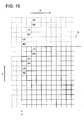
- the image recorded on the recording medium S has an area having an upper end represented by a pixel row denoted by the ink L3, L0, L3, L0, L3, L0... extending in the main scanning direction X and a left end represented by a pixel row denoted by the ink L3, R3, L3, R1, L5, R5... extending in the sub-scanning direction Y.
- a pixel row denoted by the ink L3, L0, L3, L0, L3, L0... extending in the main scanning direction X
- a left end represented by a pixel row denoted by the ink L3, R3, L3, R1, L5, R5... extending in the sub-scanning direction Y.
- a X axis is set in parallel to the main scanning direction X
- a Y axis is set in parallel to the sub-scanning direction Y so that the each pixel position of the image recorded on the recording medium S is described by a coordinate (x, y).
- data corresponding to the nozzle N to eject the ink to the pixel position described by the coordinate (x, y) is denoted by d (x, y).
- the computer 4 downloads each item of data d (x, y) which is converted from image data inputted from an unillustrated external apparatus to be recorded to a form corresponding to each nozzle N of the recording head 5 on the RAM.
- the ink is ejected from each nozzle N as Fig. 10 shows, first of all, the ink ejected from the nozzles NR0, NR1, NR3, NR4, NR5....
- the first cycle lands at each of pixel positions R0, R1, R2, R3, R4, R5, ..., shown by Fig. 14 .
- the computer 4 arranges each item of the data 0, 0, 0, d(0, 1), 0, 0... so as to correspond to each of the nozzles NR0, NR1, NR2, NR3, NR4, NR5,...in sequence.
- the computer 4 arranges each item of the data 0, 0, 0, d(0, 0), 0, 0... so as to correspond to each of the nozzles NL0, NL1, NL2, NL3, NL4, NL5,...in sequence. Then each item of data is connected to be arranged in a form of 0, 0, 0, d(0,1), 0, 0...0, 0, 0, d(0, 0), 0, 0... Incidentally, the data having a value of 0 is so-called dummy data which denotes that ink is not ejected.
- the computer 4 arranges each item of the data 0, 0, 0, d(2,1), d(1,3), d(0,5), ... so as to correspond to each of the nozzles NR0, NR1, NR2, NR3, NR4, NR5,...in sequence, and arranges and connects each item of the data 0,0,0, d (2,0), d(1, 2), d(0, 4), ... so as to correspond to each of the nozzles NR0, NL1, NL2, NL3, NL4, NL5,...in sequence.
- the computer 4 arranges the data d(x, y) corresponding to each pixel position on which the ink ejected from each of the nozzles NR0, NR1, ..., NL0, NL1,...in each ejection cycle, or arranges each item of data by corresponding 0 which is the dummy data in case the data does not exist for the corresponding pixel position, and forms a data row having an appropriate arrangement sequence then transmits the data to the head drive circuitry 51 serially.
- forming of the data row can be conducted before recording operation starts, or can be conducted parallel to the recording operation.
- the above process in the control device 9 and the process in the computer 4 are not specific processes for the recording head 5 shown by Fig. 3 , and the same processes can be applied to a case that the general recording head H shown in Fig. 24 is used.
- the recording head 5 or H moves to scan at the moving speed (2 x L x f) which is two times of the conventional moving speed (L x f), and each nozzle row of the recording head 5 or H are driven to eject in the sequence from the nozzle row at the rear section to the nozzle row on the front side in the relative moving direction (main scanning direction X) of the recording head 5 or H with respect to the recording medium S, namely driven to eject with the reverse phase.
- the recording medium S is moved by a distance which is the predetermined multiple of the pixel pitch L so as to execute subsequent scan.
- the ink is ejected from each of the nozzles N to the pixel positions other than the pixel positions on which the ink has landed through the preceding scan by the recording head 5 or H on the recording medium S.
- the ink droplets ejected from other normal nozzles N land and fill the pixel positions adjacent to the pixel positions on which the ink has not been ejected from the said nozzles N supposed to land.
- the portions to which the ink has not been ejected line up serially in the recorded image on the recording medium in the main scanning direction X and the phenomenon that the streak pattern seems in the image is prohibited.
- deterioration of the image quality is suppressed and the image quality can be improved.
- the moving speed of the recording head 5 or H becomes two times of conventional moving speed in the main scanning direction X
- the time required for image recording does not change much compared to the conventional recording method.
- the streak shape pattern to appear in the image can be prohibited, which cannot be prohibited in the conventional recording method.
- the interval between the left and right nozzle rows corresponding namely the interval between the nozzle row R3m and the nozzle row L3m, is set at 1.44 mm, then since the pixel pitch L is 70.5 ⁇ m, the interval corresponds to approximately 20.4 pixels.
- the interval between the nozzle row R3m and the nozzle row L3m are not set at an integral multiple of the pixel pitch L, for example, in case ejection timings of the nozzle rows R3m to R3m+2 and the nozzle rows L3m to L3m+2 are synchronized to eject the ink from each nozzle N, the landing position of the ink ejected from each nozzle N in the nozzle rows R3m to R3m+2 and the landing position of the ink ejected from each nozzle N in the nozzle rows L3m to L3m+2 do not align each other in the sub-scanning direction Y as Fig. 10 and Fig. 11 show.
- the ink is ejected from each nozzle N in dependent timings without synchronizing the ejection timings of the nozzle rows R3m to R3m+2 and the nozzle rows L3m to L3m+2.
- each nozzle N of the nozzle rows R3m to R3m+2 and the nozzle rows L3m to L3m+2 is not driven to eject at the dependent ejection timing.
- an ejection frequency f for each nozzle row (namely the ejection frequency for each nozzle N) of the recording head 5 is adjusted so as to align the landing positions of the ink ejected from each nozzle N of the nozzle rows R3m to R3m+2 and the landing positions of the ink ejected from each nozzle N of the nozzle rows L3m to L3m+2 in the sub-scanning direction Y.
- the moving speed (2 x L x f) of the recording head 5 is changed in accordance with the change of the ejection frequency f.
- the recording head 5 (refer to Fig. 3 ) is driven by each drive phase of a three-phase current.
- 256 nozzles N are disposed respectively for left and right sets, namely a total of 512 nozzles are disposed.
- the image is recorded on the recording medium S using the above recording head 5, with a resolution of 720 dpi, namely image forming can be conducted with two times of the resolution of the first embodiment.
- the pixel pitch L is 35.3 ⁇ m and the intervals q between the three nozzle rows on left and right are set at 1/3 of the pitch, namely 11.8 ⁇ m respectively.
- an interval between left and right nozzle rows corresponding, namely the interval between the nozzle row R3m and the nozzle row L3m is 1.44 mm and the frequency f for each nozzle row (namely the ejection frequency for each nozzle N) is set, for example, at around 6.7 kHz, which are same as the first embodiment.
- the interval q between each of the adjacent nozzles in the same set of the nozzle rows in the sub-scanning direction Y is set at four times of the pixel pitch L, and in the left and right sets of the nozzles rows, the nozzles N are displaced by two times of the pixel pitches L in the sub-scanning direction Y, which is different from the first embodiment.
- the recording head 5 is moved for scan in the main scanning direction X at a moving speed of L x f and the nozzles NR3m, NR3m+1 and NR3m+2 and the nozzles NL3m, NL3m+1 and NL3m+2 of the recording ahead 5 of the present invention are respectively driven to eject with normal phase as Fig. 25 shows and with three-phase drive which has been carried out conventionally, as Fig. 16 shows, the ink ejected from each nozzle N of nozzle NR3m to Nr3m+2 and nozzle NL3m to NL3m+2 through one scan of the recording head 5 in the main scanning direction X lands on every other pixel in the sub-scanning direction Y.
- Fig. 16 shows, in the present embodiment, in case ejection drive is conducted with three-phase drive which is conventionally carried out as above, the recording head 5 lands the ink through two scans (namely, two passes) on each pixel on the recording medium S so as to record the image on the recording medium S.
- the control device 9 sets the moving speed in the main scanning direction of the carriage equipped with the recording head 5 at 2 x L x fin the scan drive mechanism 10, and sets the head drive circuitry 51 so that ejection drive of the nozzle rows R3m to R3m+2 and the nozzle rows L3m to L3m+2 of the recording head 5 is carried out in a sequence from the nozzle row at the end to the nozzle row in front in a relative moving direction (main scanning direction X) of the recording head 5 with respect to the recording medium S (namely ejection drive is carried out with the reverse phase).
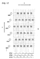
- the recording head 5 moves to scan in the main scanning direction S at the moving speed of 2 x L x f, thus from each of nozzles NR3m, NR3m+1 and NR3m+2 of the nozzle rows R3m, R3m+1 and R3m+2 of the recording head 5, the ink is ejected to every other pixels in the main scanning direction X as Fig. 17 shows.
- each of nozzles NR3m, NR3m+1 and NR3m+2 are set so that the interval between the adjacent nozzles N in the sub-scanning direction Y is four times of the pixel pitch L, therefore the ink is ejected to every fourth pixel in the sub-scanning direction Y.
- each of the nozzles NL3 m, NL3m+1 and NL3m+2 eject the ink to every other pixel position which is adjacent to the pixel position to which the ink has been ejected from each of the nozzles NR3m, Nr3m+1 and NR3m+2.
- the control device 9 drives the drive motor 22 to move the recording medium S by a distance equal to a predetermined multiple of the pixel pitch in the conveyance direction Z (sub-scanning direction Y) and stops.
- the subsequent scan by the recording head 5 in the main scanning direction X in the opposite direction the ink is ejected from each nozzle to the pixel position other than the pixel position to which the ink has landed on the recording medium S by the preceding scans of the recording head 5.
- the control device 9 moves the recording S in the sub-scanning direction Y (for example, upward in the figure) by, for example, a distance equal to 13 times of the pixel pitch, and stops, then in subsequent scan by the recording head 5 in the main scanning direction X in the opposite direction, as Fig. 19 shows, each nozzle ejects ink to the pixel position which locates lower left in the figure with respect to the pixel position to which the ink has been landed on the recording medium S in the preceding scan by the recording head 5.
- W 1 has to be set by appropriately increasing or decreasing a calculated value of 12 times of the pixel pitch.
- W1 is made 13 times of the pixel pitch.
- the control device 9 moves the recording medium S in the sub-scanning direction Y (for example, upward in the figure) by a distance of 11 times of the pixel pitch again and stops to perform third scan by the recording head 5.
- each nozzle ejects the ink onto the pixel position which is on the right in the figure of the pixel position onto which the ink has landed in the first scan of the recording head 5 on the recording medium S.
- the control device 9 When third scan by the recording head 5 is completed, the control device 9 further moves the recording medium S in the sub-scanning direction Y (for example, upward in the figure) by a distance of 13 times of the pixel pitch and stops to perform fourth scan by the recording head 5.
- each nozzle In fourth scan by the recording ahead, each nozzle ejects the ink onto the pixel position below the pixel position in the figure onto which the ink has landed in the first scan of the recording head 5 on the recording medium S.
- the ink can be landed on each pixel on the recording medium S to record the image on the recording medium S.
- Fig. 19 shows, at least it is avoided that the ink ejected from the same nozzle N of the recording head 5 lands on the adjacent pixel position on the recording medium S.
- the ink ejected from other normal nozzle lands and fills the pixel position adjacent to the pixel position to which the ink, which has not been ejected form the defective nozzle N, is supposed to land.
- the image can be recorded on the recording medium S through two scans (so-called two pass) by the recording head 5, though the recording method of the present invention shown in Fig. 18 requires four scans (so-called four passes) by the recording head 5 to record the image on the recording medium S.
- the moving speed of the recording head 5 in the main scanning direction X is two times of the conventional moving speed, there is not much difference of the time required for image recording compared with that in the conventional recording method. Namely, in the present embodiment as well, the phenomenon that the streak pattern contains in the image which cannot be avoided in the conventional method can be avoided with almost the same recording time as that of the conventional method.
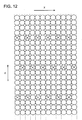
- Fig. 12 it is configured that one nozzle N ejects the ink to every other pixel in the main scanning direction X and the other nozzle N eject the ink so as to fill the intervals between the pixel positions. Namely, the ink is ejected from two nozzles N so as to lines up alternately in the main scanning direction X.
- the control device 9 concerning each ejection cycle carried out within one scan by the recording ahead 5 in the main scanning direction X, the control device 9 provides an ejection cycle where the ink is ejected from each nozzle N and another ejection cycle where the ink is not ejected from each nozzle N in an ejection operation of each nozzle N.
- the recording method of the present invention is employed in the same manner as that in the above first and the second embodiment.
- the control device 9 moves the recording head 5 at the moving speed of 2 x L x f in the main scanning direction to scan, and also drives the nozzle rows R3m to R3m+2 and the nozzle rows L3m to L3m+2 of the recording head 5 to eject with the reverse phase.
- the recording medium S is conveyed in the conveyance direction Z (sub-scanning direction Y) by a distance of a predetermined multiple of the pixel pitch, which is the same as in the first and second embodiment.
- the control device 9 in the ejection operation of each nozzle N for each ejection cycle carried out within one scan by the recording head 5 in the main scanning direction X, the control device 9 is configured to set that the ejection cycle where the ink is ejected from each nozzle N and the ejection cycle where the ink is not ejected from each nozzle N are alternated.
- whether or not the ejection cycle where ink is not ejected is provided can be set in accordance with the setting input of a user. Also, how the ejection cycles where the ink is ejected from each nozzle N and the ejection cycle where the ink is not ejected from each nozzle N are set can be set appropriately in advance or when the above setting input is conducted by the user.
- Fig. 20 shows, in the first ejection cycle, the ink is ejected from each of nozzles NR3m, NR3m+1 and NR3m+2 in the nozzle rows R3m, R3m+1 and R3m+2 of the recording head 5 to the pixel positions corresponding on the recording medium S, and the ink is not ejected in the subsequent ejection cycle.
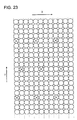
- Fig. 3 shows, if 256 nozzles respectively for left and right sets, a total of 512 nozzles are described, the figure becomes complicated, thus in Figs. 21 to 23 including Fig. 20 , description is given supposing that 12 nozzles respectively for left and right groups i.e. the total of 24 nozzles (NL0 to NL11 and NR0 to NR 11) record the image.
- the ink is ejected to every fourth pixel position corresponding to each of nozzles NR3m, NR3m+1 and NR3m+2 in the main canning direction X on the recording medium S. Also, since the interval q between the adjacent nozzles NR3m, NR3m+1 and NR3m+2 NR3m in the sub-scanning direction Y is set two times of the pixel pitch L, the ink is ejected to every other pixel in the sub-scanning direction Y.
- each nozzle NL3m, NL3m+1 and NL3m+2 of the nozzle rows LM3m, L3m+1 and L3m+2 of the recording head 5 also eject the ink in the same manner however, the nozzles NL3m, NL3m+l and NL3m+2 are displaced by one pixel pitch L with respect to the nozzles NR3m, NR3m+1 and NR3m+2.
- FIG. 21 shows, from each of nozzles NL3m, NL3m+1 and NL3m+2, the ink is ejected to the pixel position adjacent to the pixel position in the sub-scanning direction Y to which the ink has been ejected from each of nozzles NR3m, NR3m+1 and NR3m+2.
- the control device 9 drives the drive motor 22 so as to convey the recording medium S in the conveyance direction Z (sub-scanning direction Y) by a distance of a predetermined multiple of the pixel pitch and stops, then moves the recording head 5 in the main scanning direction X in the opposite direction for scan.
- the control device 9 moves the recording medium S in the sub-scanning direction Y (for example, upward in the figure) by a distance of, for example, six times of the pixel pitch and stops.
- Fig. 22 shows, since W2 is one time of the pixel pitch, the number of the nozzles is 24 and the number of the multi passes W3 is four, the moving distance W 1 is six times of the pixel pitch.
- Fig. 22 shows, for example, the ink is ejected from each nozzle to the pixel position adjacent to the pixel position to which the ink has been landed through the preceding scan by the recording head 5 on the recording medium S.
- Fig. 22 reveals, in case of the present embodiment, image recording on the recording medium S cannot be completed through two scans (namely two passes).
- the control device 9 further moves the recording medium S by a distance of, for example, six times of the pixel pitch in the sub-scanning direction Y (for example, upward in the figure) and stops.
- third scan by the recording head 5 in the main scanning direction X is conducted to eject ink to the adjacent pixel position from each nozzles N.
- the recording medium S is moved by a distance, for example, six times of the pixel pitch in the sub-scanning direction Y (for example upward in the figure) and stops.
- fourth scan by the recording head 5 in the main scanning is conducted to eject ink to the adjacent pixel position from each nozzles N.
- the ink is landed onto each pixel on the recording medium S and the image can be recorded on the recording medium S.
- the pixel positions in the interval portion can be filled with a plurality of ink droplets ejected from a plurality of other nozzles.
- X denotes the pixel positions to which the ink supposed to be ejected from the defective nozzle N which cannot eject ink normally due to nozzle failure
- Fig. 23 shows, the pixel positions to which the ink is not ejected exist every three pixels.
- the plurality of the pixel positions in the portion between the pixel positions to which the ink in not ejected from the defective nozzles N can be filled by landing of the plurality of the ink droplets ejected from the plurality of the normal nozzles N. Therefore, the pixel positions to which the ink is not ejected in the image are spread sparsely, and appearing of the streak patter in the recorded image on the recording medium S can be appropriately prohibited.
Landscapes
- Engineering & Computer Science (AREA)
- Quality & Reliability (AREA)
- Ink Jet (AREA)
Claims (6)
- Tintenstrahlaufzeichnungsvorrichtung (1), Folgendes umfassend:einen Aufzeichnungskopf (5), der durch jede Antriebsphase eines Dreiphasenstroms angetrieben wird, mit Düsenreihen von drei Düsenreihen (3m, 3m+1, 3m+2), in welchen eine Vielzahl von Düsen (N3m, N3m+1, N3m+2) in einer versetzten Anordnung mit einem Intervall von L/3 in der Haupt-Scan-Richtung angeordnet sind, wobei L einen Pixelabstand bezeichnet; undein Steuergerät (9), um jede Düsenreihe in dem Aufzeichnungskopf in einer Sequenz von einer der drei Düsenreihen, die an einem Ende (N3m+2) angeordnet ist, zu einer der drei Düsenreihen, die vorne (N3m) angeordnet ist, in einer relativen Bewegungsrichtung des Aufzeichnungskopfes (5) bezüglich eines Aufzeichnungsmediums (S) anzutreiben, und um den Aufzeichnungskopf (5) mit einer Bewegungsgeschwindigkeit von 2 x L x f in einer Hauptscanrichtung (X) zu bewegen, wobei f eine vorbestimmte Ausstoßfrequenz für jede Düsenreihe des Aufzeichnungskopfes darstellt, wobeidas Steuergerät (9) Mehrdurchgangsaufzeichnen in einer solchen Weise durchführt, dass wenn ein Scandurchgang mit dem Aufzeichnungskopf in der Hauptscanrichtung (X) abgeschlossen ist, das Steuergerät (9) das Aufzeichnungsmedium (S) bezüglich des Aufzeichnungskopfes in einer Subscanrichtung (Y), die senkrecht zur Hauptscanrichtung (X) ist, um eine Distanz von einem vorbestimmten Vielfachen des Pixelabstands bewegt, und das Steuergerät (9) in einem anschließenden Scandurchgang in der Hauptscanrichtung (X) den Aufzeichnungskopf (5) so steuert, dass Tinte aus jeder Düse an eine Pixelposition ausgestoßen wird, die anders ist als eine Pixelposition, wo die Tinte in dem vorhergehenden Scan durch den Aufzeichnungskopf (5) auf das Aufzeichnungsmedium (S) aufgetroffen ist, so dass ein Bild auf dem Aufzeichnungsmedium durch Auftreffen der Tinte auf jedem Pixel auf dem Aufzeichnungsmedium aufgezeichnet wird, dadurch gekennzeichnet, dass die Pixelpositionen in einer Reihe in der Hauptscanrichtung mit Tintentröpfchen aus verschiedenen Düsen gefüllt sind.
- Tintenstrahlaufzeichnungsvorrichtung nach Anspruch 1, wobei der Aufzeichnungskopf (5) mit zwei Serien von Düsenreihen der drei Düsenreihen (NL, NR) vorgesehen ist, die parallel in der Hauptscanrichtung (X) angeordnet sind, ein Intervall (q) zwischen benachbarten Düsen in der untergeordneten Scanrichtung in einer gleichen Düsenreihe auf das Zweifache des Pixelabstands eingestellt ist und die Düsen in einer Serie der Düsenreihen (NL) um einen Pixelabstand in der Subscanrichtung (Y) bezüglich der Düsen in einer anderen Serie der Düsenreihen (NR). verschoben sind
- Tintenstrahlaufzeichnungsvorrichtung nach Anspruch 1, wobei der Aufzeichnungskopf (5) mit zwei Serien der Düsenreihen der drei Düsenreihen (NL, NR) bereitgestellt ist, die parallel in der Hauptscanrichtung (X) angeordnet sind, ein Intervall (q) zwischen benachbarten Düsen in der Subscanrichtung in einer gleichen Düsenreihe so eingestellt ist, dass es das Vierfache des Pixelabstands beträgt, und die Düsen in einer Serie der Düsenreihen (NL) um zwei Pixelabstände in der Subscanrichtung (Y) bezüglich der Düsen in einer anderen Serie der Düsenreihen (NR) verschoben sind.
- Tintenstrahlaufzeichnungsvorrichtung nach Anspruch 2 oder 3, wobei die zwei Serien der Düsenreihen (NL, NR) voneinander um einen Abstand verschoben sind, der kein ganzzahliges Vielfaches des Pixelabstands in der Hauptscanrichtung ist.
- Tintenstrahlaufzeichnungsvorrichtung nach einem der Ansprüche 1 bis 4, wobei ein Tintenausstoßvorgang aus jeder Düse für jeden Ausstoßzyklus, der innerhalb eines Scans, durch den Aufzeichnungskopf in der Hauptscanrichtung durchgeführt wird, der Steuerabschnitt einen Ausstoßzyklus, bei dem die Tinte aus jeder Düse ausgestoßen wird, und einen anderen Ausstoßzyklus, bei dem die Tinte nicht aus der Düse ausgestoßen wird, vorsieht.
- Tintenstrahlaufzeichnungsvorrichtung nach einem der Ansprüche 1 bis 5, wobei das Steuergerät die Tintenstrahlaufzeichnungsvorrichtung auf eine solche Weise steuert, dass falls ein Abstand W2 zwischen benachbarten Düsen in der Subscanrichtung auf dem Aufzeichnungskopf gleich einem Pixelabstand ist, der bewegliche Abstand des Aufzeichnungsmediums gleich W1 in der Subscanrichtung ist, und falls der Abstand W2 das Zweifache oder mehr als das das Zweifache des Pixelabstands beträgt, das Aufzeichnungsmedium wiederholt um den beweglichen Abstand, der größer ist als W1, und um den beweglichen Abstand, der kleiner ist als W1, abwechselnd nach jedem Scandurchgang bewegt wird, wobei W1 die Anzahl von Düsen auf einem Aufzeichnungskopf x W2 / W3 bezeichnet, und W3 die Anzahl von Durchgängen bezeichnet.
Applications Claiming Priority (2)
| Application Number | Priority Date | Filing Date | Title |
|---|---|---|---|
| JP2009037742 | 2009-02-20 | ||
| PCT/JP2010/052044 WO2010095565A1 (ja) | 2009-02-20 | 2010-02-12 | インクジェット記録装置 |
Publications (3)
| Publication Number | Publication Date |
|---|---|
| EP2399746A1 EP2399746A1 (de) | 2011-12-28 |
| EP2399746A4 EP2399746A4 (de) | 2013-08-07 |
| EP2399746B1 true EP2399746B1 (de) | 2015-09-23 |
Family
ID=42633848
Family Applications (1)
| Application Number | Title | Priority Date | Filing Date |
|---|---|---|---|
| EP10743692.5A Active EP2399746B1 (de) | 2009-02-20 | 2010-02-12 | Tintenstrahlaufzeichnungsvorrichtung |
Country Status (4)
| Country | Link |
|---|---|
| US (1) | US8469473B2 (de) |
| EP (1) | EP2399746B1 (de) |
| JP (1) | JP5482782B2 (de) |
| WO (1) | WO2010095565A1 (de) |
Families Citing this family (3)
| Publication number | Priority date | Publication date | Assignee | Title |
|---|---|---|---|---|
| JP6399862B2 (ja) * | 2014-08-29 | 2018-10-03 | キヤノン株式会社 | 液体吐出装置および液体吐出ヘッド |
| JP7350457B2 (ja) * | 2020-07-20 | 2023-09-26 | 株式会社ミマキエンジニアリング | 印刷装置、及び印刷方法 |
| CN115989090B (zh) * | 2020-09-03 | 2023-12-15 | 柯尼卡美能达株式会社 | 图案形成方法以及喷墨印刷装置 |
Family Cites Families (5)
| Publication number | Priority date | Publication date | Assignee | Title |
|---|---|---|---|---|
| JPH05338210A (ja) | 1992-06-11 | 1993-12-21 | Olympus Optical Co Ltd | マルチヘッドプリンタ |
| JP4146208B2 (ja) * | 2002-10-21 | 2008-09-10 | エスアイアイ・プリンテック株式会社 | インクジェット式記録装置及びインクジェット式記録方法 |
| JP3788471B2 (ja) | 2004-07-14 | 2006-06-21 | コニカミノルタエムジー株式会社 | インクジェット記録装置及びインクジェット記録方法 |
| JP2007234718A (ja) | 2006-02-28 | 2007-09-13 | Matsushita Electric Ind Co Ltd | 半導体集積回路装置 |
| JP5034591B2 (ja) | 2007-03-23 | 2012-09-26 | コニカミノルタホールディングス株式会社 | インクジェット記録装置 |
-
2010
- 2010-02-12 EP EP10743692.5A patent/EP2399746B1/de active Active
- 2010-02-12 JP JP2011500581A patent/JP5482782B2/ja active Active
- 2010-02-12 WO PCT/JP2010/052044 patent/WO2010095565A1/ja not_active Ceased
- 2010-02-12 US US13/201,884 patent/US8469473B2/en not_active Expired - Fee Related
Also Published As
| Publication number | Publication date |
|---|---|
| EP2399746A1 (de) | 2011-12-28 |
| JP5482782B2 (ja) | 2014-05-07 |
| WO2010095565A1 (ja) | 2010-08-26 |
| US20110298852A1 (en) | 2011-12-08 |
| US8469473B2 (en) | 2013-06-25 |
| EP2399746A4 (de) | 2013-08-07 |
| JPWO2010095565A1 (ja) | 2012-08-23 |
Similar Documents
| Publication | Publication Date | Title |
|---|---|---|
| JP2012040806A (ja) | 記録装置および記録方法 | |
| CN107428161B (zh) | 喷墨记录装置及喷墨记录方法 | |
| CN101186147A (zh) | 打印装置和打印方法 | |
| JP4350408B2 (ja) | 記録ヘッド用基板、記録ヘッド、及び記録装置 | |
| JP5339801B2 (ja) | 画像処理装置および画像処理方法 | |
| EP2399746B1 (de) | Tintenstrahlaufzeichnungsvorrichtung | |
| JPH1034935A (ja) | 液体インクプリンタのドット付着管理方法 | |
| CN109476157B (zh) | 有多个对齐排列液滴喷射器的喷墨打印头及其使用方法 | |
| JP4566397B2 (ja) | インクジェット記録装置、及びインクジェット記録方法 | |
| JP2021091221A (ja) | 相補的で不規則な境界を有するスプライシングストリップの印刷方法 | |
| JP5882660B2 (ja) | 記録装置 | |
| JPH0970959A (ja) | 記録装置 | |
| JP5898423B2 (ja) | インクジェット記録装置および記録方法 | |
| JPH1134360A (ja) | インクジェットプリンタ | |
| JP5084413B2 (ja) | 印刷装置および印刷方法 | |
| US7618113B2 (en) | Liquid discharge apparatus and liquid discharge method | |
| WO2008035553A1 (fr) | Appareil de commande pour tête d'impression à jet d'encre | |
| JP2007144847A (ja) | インクジェット印画装置 | |
| JP5906066B2 (ja) | ヘッド基板、そのヘッド基板を用いたインクジェット記録ヘッド、及び、その記録ヘッドを用いた記録装置 | |
| JP2008100483A (ja) | ヘッド基板、記録ヘッド、及び記録装置 | |
| JP5206374B2 (ja) | 記録ヘッド駆動方法、記録ヘッドおよびインクジェット記録装置 | |
| US20070103497A1 (en) | Driving method of ink-jet printer and its driving apparatus | |
| EP1216154B1 (de) | Tintenstrahldruckverfahren mit verbesserter überlappung und zugehöriges druckgerät | |
| JP4402658B2 (ja) | インクジェット記録装置 | |
| JP5034591B2 (ja) | インクジェット記録装置 |
Legal Events
| Date | Code | Title | Description |
|---|---|---|---|
| PUAI | Public reference made under article 153(3) epc to a published international application that has entered the european phase |
Free format text: ORIGINAL CODE: 0009012 |
|
| 17P | Request for examination filed |
Effective date: 20110727 |
|
| AK | Designated contracting states |
Kind code of ref document: A1 Designated state(s): AT BE BG CH CY CZ DE DK EE ES FI FR GB GR HR HU IE IS IT LI LT LU LV MC MK MT NL NO PL PT RO SE SI SK SM TR |
|
| DAX | Request for extension of the european patent (deleted) | ||
| A4 | Supplementary search report drawn up and despatched |
Effective date: 20130709 |
|
| RIC1 | Information provided on ipc code assigned before grant |
Ipc: B41J 2/01 20060101AFI20130703BHEP Ipc: B41J 2/045 20060101ALI20130703BHEP Ipc: B41J 2/055 20060101ALI20130703BHEP Ipc: B41J 2/145 20060101ALI20130703BHEP |
|
| 17Q | First examination report despatched |
Effective date: 20140612 |
|
| GRAP | Despatch of communication of intention to grant a patent |
Free format text: ORIGINAL CODE: EPIDOSNIGR1 |
|
| INTG | Intention to grant announced |
Effective date: 20150610 |
|
| GRAS | Grant fee paid |
Free format text: ORIGINAL CODE: EPIDOSNIGR3 |
|
| GRAA | (expected) grant |
Free format text: ORIGINAL CODE: 0009210 |
|
| AK | Designated contracting states |
Kind code of ref document: B1 Designated state(s): AT BE BG CH CY CZ DE DK EE ES FI FR GB GR HR HU IE IS IT LI LT LU LV MC MK MT NL NO PL PT RO SE SI SK SM TR |
|
| REG | Reference to a national code |
Ref country code: GB Ref legal event code: FG4D |
|
| REG | Reference to a national code |
Ref country code: CH Ref legal event code: EP |
|
| REG | Reference to a national code |
Ref country code: AT Ref legal event code: REF Ref document number: 751006 Country of ref document: AT Kind code of ref document: T Effective date: 20151015 |
|
| REG | Reference to a national code |
Ref country code: IE Ref legal event code: FG4D |
|
| REG | Reference to a national code |
Ref country code: DE Ref legal event code: R096 Ref document number: 602010027738 Country of ref document: DE |
|
| REG | Reference to a national code |
Ref country code: FR Ref legal event code: PLFP Year of fee payment: 7 |
|
| REG | Reference to a national code |
Ref country code: NL Ref legal event code: MP Effective date: 20150923 |
|
| PG25 | Lapsed in a contracting state [announced via postgrant information from national office to epo] |
Ref country code: FI Free format text: LAPSE BECAUSE OF FAILURE TO SUBMIT A TRANSLATION OF THE DESCRIPTION OR TO PAY THE FEE WITHIN THE PRESCRIBED TIME-LIMIT Effective date: 20150923 Ref country code: GR Free format text: LAPSE BECAUSE OF FAILURE TO SUBMIT A TRANSLATION OF THE DESCRIPTION OR TO PAY THE FEE WITHIN THE PRESCRIBED TIME-LIMIT Effective date: 20151224 Ref country code: LV Free format text: LAPSE BECAUSE OF FAILURE TO SUBMIT A TRANSLATION OF THE DESCRIPTION OR TO PAY THE FEE WITHIN THE PRESCRIBED TIME-LIMIT Effective date: 20150923 Ref country code: NO Free format text: LAPSE BECAUSE OF FAILURE TO SUBMIT A TRANSLATION OF THE DESCRIPTION OR TO PAY THE FEE WITHIN THE PRESCRIBED TIME-LIMIT Effective date: 20151223 Ref country code: LT Free format text: LAPSE BECAUSE OF FAILURE TO SUBMIT A TRANSLATION OF THE DESCRIPTION OR TO PAY THE FEE WITHIN THE PRESCRIBED TIME-LIMIT Effective date: 20150923 |
|
| REG | Reference to a national code |
Ref country code: LT Ref legal event code: MG4D |
|
| REG | Reference to a national code |
Ref country code: AT Ref legal event code: MK05 Ref document number: 751006 Country of ref document: AT Kind code of ref document: T Effective date: 20150923 |
|
| PG25 | Lapsed in a contracting state [announced via postgrant information from national office to epo] |
Ref country code: SE Free format text: LAPSE BECAUSE OF FAILURE TO SUBMIT A TRANSLATION OF THE DESCRIPTION OR TO PAY THE FEE WITHIN THE PRESCRIBED TIME-LIMIT Effective date: 20150923 Ref country code: HR Free format text: LAPSE BECAUSE OF FAILURE TO SUBMIT A TRANSLATION OF THE DESCRIPTION OR TO PAY THE FEE WITHIN THE PRESCRIBED TIME-LIMIT Effective date: 20150923 |
|
| PG25 | Lapsed in a contracting state [announced via postgrant information from national office to epo] |
Ref country code: NL Free format text: LAPSE BECAUSE OF FAILURE TO SUBMIT A TRANSLATION OF THE DESCRIPTION OR TO PAY THE FEE WITHIN THE PRESCRIBED TIME-LIMIT Effective date: 20150923 |
|
| PG25 | Lapsed in a contracting state [announced via postgrant information from national office to epo] |
Ref country code: EE Free format text: LAPSE BECAUSE OF FAILURE TO SUBMIT A TRANSLATION OF THE DESCRIPTION OR TO PAY THE FEE WITHIN THE PRESCRIBED TIME-LIMIT Effective date: 20150923 Ref country code: SK Free format text: LAPSE BECAUSE OF FAILURE TO SUBMIT A TRANSLATION OF THE DESCRIPTION OR TO PAY THE FEE WITHIN THE PRESCRIBED TIME-LIMIT Effective date: 20150923 Ref country code: ES Free format text: LAPSE BECAUSE OF FAILURE TO SUBMIT A TRANSLATION OF THE DESCRIPTION OR TO PAY THE FEE WITHIN THE PRESCRIBED TIME-LIMIT Effective date: 20150923 Ref country code: IT Free format text: LAPSE BECAUSE OF FAILURE TO SUBMIT A TRANSLATION OF THE DESCRIPTION OR TO PAY THE FEE WITHIN THE PRESCRIBED TIME-LIMIT Effective date: 20150923 Ref country code: IS Free format text: LAPSE BECAUSE OF FAILURE TO SUBMIT A TRANSLATION OF THE DESCRIPTION OR TO PAY THE FEE WITHIN THE PRESCRIBED TIME-LIMIT Effective date: 20160123 Ref country code: CZ Free format text: LAPSE BECAUSE OF FAILURE TO SUBMIT A TRANSLATION OF THE DESCRIPTION OR TO PAY THE FEE WITHIN THE PRESCRIBED TIME-LIMIT Effective date: 20150923 |
|
| PG25 | Lapsed in a contracting state [announced via postgrant information from national office to epo] |
Ref country code: PT Free format text: LAPSE BECAUSE OF FAILURE TO SUBMIT A TRANSLATION OF THE DESCRIPTION OR TO PAY THE FEE WITHIN THE PRESCRIBED TIME-LIMIT Effective date: 20160125 Ref country code: RO Free format text: LAPSE BECAUSE OF FAILURE TO SUBMIT A TRANSLATION OF THE DESCRIPTION OR TO PAY THE FEE WITHIN THE PRESCRIBED TIME-LIMIT Effective date: 20150923 Ref country code: AT Free format text: LAPSE BECAUSE OF FAILURE TO SUBMIT A TRANSLATION OF THE DESCRIPTION OR TO PAY THE FEE WITHIN THE PRESCRIBED TIME-LIMIT Effective date: 20150923 Ref country code: PL Free format text: LAPSE BECAUSE OF FAILURE TO SUBMIT A TRANSLATION OF THE DESCRIPTION OR TO PAY THE FEE WITHIN THE PRESCRIBED TIME-LIMIT Effective date: 20150923 Ref country code: BE Free format text: LAPSE BECAUSE OF NON-PAYMENT OF DUE FEES Effective date: 20160229 |
|
| REG | Reference to a national code |
Ref country code: DE Ref legal event code: R097 Ref document number: 602010027738 Country of ref document: DE |
|
| PLBE | No opposition filed within time limit |
Free format text: ORIGINAL CODE: 0009261 |
|
| STAA | Information on the status of an ep patent application or granted ep patent |
Free format text: STATUS: NO OPPOSITION FILED WITHIN TIME LIMIT |
|
| 26N | No opposition filed |
Effective date: 20160624 |
|
| PG25 | Lapsed in a contracting state [announced via postgrant information from national office to epo] |
Ref country code: DK Free format text: LAPSE BECAUSE OF FAILURE TO SUBMIT A TRANSLATION OF THE DESCRIPTION OR TO PAY THE FEE WITHIN THE PRESCRIBED TIME-LIMIT Effective date: 20150923 |
|
| PG25 | Lapsed in a contracting state [announced via postgrant information from national office to epo] |
Ref country code: LU Free format text: LAPSE BECAUSE OF FAILURE TO SUBMIT A TRANSLATION OF THE DESCRIPTION OR TO PAY THE FEE WITHIN THE PRESCRIBED TIME-LIMIT Effective date: 20160212 Ref country code: MC Free format text: LAPSE BECAUSE OF FAILURE TO SUBMIT A TRANSLATION OF THE DESCRIPTION OR TO PAY THE FEE WITHIN THE PRESCRIBED TIME-LIMIT Effective date: 20150923 |
|
| REG | Reference to a national code |
Ref country code: CH Ref legal event code: PL |
|
| PG25 | Lapsed in a contracting state [announced via postgrant information from national office to epo] |
Ref country code: CH Free format text: LAPSE BECAUSE OF NON-PAYMENT OF DUE FEES Effective date: 20160229 Ref country code: LI Free format text: LAPSE BECAUSE OF NON-PAYMENT OF DUE FEES Effective date: 20160229 |
|
| PG25 | Lapsed in a contracting state [announced via postgrant information from national office to epo] |
Ref country code: SI Free format text: LAPSE BECAUSE OF FAILURE TO SUBMIT A TRANSLATION OF THE DESCRIPTION OR TO PAY THE FEE WITHIN THE PRESCRIBED TIME-LIMIT Effective date: 20150923 |
|
| REG | Reference to a national code |
Ref country code: IE Ref legal event code: MM4A |
|
| PG25 | Lapsed in a contracting state [announced via postgrant information from national office to epo] |
Ref country code: BE Free format text: LAPSE BECAUSE OF FAILURE TO SUBMIT A TRANSLATION OF THE DESCRIPTION OR TO PAY THE FEE WITHIN THE PRESCRIBED TIME-LIMIT Effective date: 20150923 |
|
| REG | Reference to a national code |
Ref country code: FR Ref legal event code: PLFP Year of fee payment: 8 |
|
| PG25 | Lapsed in a contracting state [announced via postgrant information from national office to epo] |
Ref country code: IE Free format text: LAPSE BECAUSE OF NON-PAYMENT OF DUE FEES Effective date: 20160212 |
|
| PGFP | Annual fee paid to national office [announced via postgrant information from national office to epo] |
Ref country code: FR Payment date: 20170112 Year of fee payment: 8 |
|
| PG25 | Lapsed in a contracting state [announced via postgrant information from national office to epo] |
Ref country code: MT Free format text: LAPSE BECAUSE OF FAILURE TO SUBMIT A TRANSLATION OF THE DESCRIPTION OR TO PAY THE FEE WITHIN THE PRESCRIBED TIME-LIMIT Effective date: 20150923 |
|
| PG25 | Lapsed in a contracting state [announced via postgrant information from national office to epo] |
Ref country code: CY Free format text: LAPSE BECAUSE OF FAILURE TO SUBMIT A TRANSLATION OF THE DESCRIPTION OR TO PAY THE FEE WITHIN THE PRESCRIBED TIME-LIMIT Effective date: 20150923 Ref country code: SM Free format text: LAPSE BECAUSE OF FAILURE TO SUBMIT A TRANSLATION OF THE DESCRIPTION OR TO PAY THE FEE WITHIN THE PRESCRIBED TIME-LIMIT Effective date: 20150923 Ref country code: HU Free format text: LAPSE BECAUSE OF FAILURE TO SUBMIT A TRANSLATION OF THE DESCRIPTION OR TO PAY THE FEE WITHIN THE PRESCRIBED TIME-LIMIT; INVALID AB INITIO Effective date: 20100212 |
|
| PG25 | Lapsed in a contracting state [announced via postgrant information from national office to epo] |
Ref country code: MK Free format text: LAPSE BECAUSE OF FAILURE TO SUBMIT A TRANSLATION OF THE DESCRIPTION OR TO PAY THE FEE WITHIN THE PRESCRIBED TIME-LIMIT Effective date: 20150923 Ref country code: TR Free format text: LAPSE BECAUSE OF FAILURE TO SUBMIT A TRANSLATION OF THE DESCRIPTION OR TO PAY THE FEE WITHIN THE PRESCRIBED TIME-LIMIT Effective date: 20150923 Ref country code: MT Free format text: LAPSE BECAUSE OF FAILURE TO SUBMIT A TRANSLATION OF THE DESCRIPTION OR TO PAY THE FEE WITHIN THE PRESCRIBED TIME-LIMIT Effective date: 20160229 |
|
| PG25 | Lapsed in a contracting state [announced via postgrant information from national office to epo] |
Ref country code: BG Free format text: LAPSE BECAUSE OF FAILURE TO SUBMIT A TRANSLATION OF THE DESCRIPTION OR TO PAY THE FEE WITHIN THE PRESCRIBED TIME-LIMIT Effective date: 20150923 |
|
| REG | Reference to a national code |
Ref country code: FR Ref legal event code: ST Effective date: 20181031 |
|
| PG25 | Lapsed in a contracting state [announced via postgrant information from national office to epo] |
Ref country code: FR Free format text: LAPSE BECAUSE OF NON-PAYMENT OF DUE FEES Effective date: 20180228 |
|
| P01 | Opt-out of the competence of the unified patent court (upc) registered |
Effective date: 20230510 |
|
| PGFP | Annual fee paid to national office [announced via postgrant information from national office to epo] |
Ref country code: GB Payment date: 20260106 Year of fee payment: 17 |
|
| PGFP | Annual fee paid to national office [announced via postgrant information from national office to epo] |
Ref country code: DE Payment date: 20251216 Year of fee payment: 17 |