WO2010109680A1 - Bouchon de génération d'eau moussante - Google Patents
Bouchon de génération d'eau moussante Download PDFInfo
- Publication number
- WO2010109680A1 WO2010109680A1 PCT/JP2009/056852 JP2009056852W WO2010109680A1 WO 2010109680 A1 WO2010109680 A1 WO 2010109680A1 JP 2009056852 W JP2009056852 W JP 2009056852W WO 2010109680 A1 WO2010109680 A1 WO 2010109680A1
- Authority
- WO
- WIPO (PCT)
- Prior art keywords
- water flow
- water
- air
- accelerated
- foam
- Prior art date
- Legal status (The legal status is an assumption and is not a legal conclusion. Google has not performed a legal analysis and makes no representation as to the accuracy of the status listed.)
- Ceased
Links
Images



Classifications
-
- E—FIXED CONSTRUCTIONS
- E03—WATER SUPPLY; SEWERAGE
- E03C—DOMESTIC PLUMBING INSTALLATIONS FOR FRESH WATER OR WASTE WATER; SINKS
- E03C1/00—Domestic plumbing installations for fresh water or waste water; Sinks
- E03C1/02—Plumbing installations for fresh water
- E03C1/08—Jet regulators or jet guides, e.g. anti-splash devices
- E03C1/084—Jet regulators with aerating means
-
- B—PERFORMING OPERATIONS; TRANSPORTING
- B01—PHYSICAL OR CHEMICAL PROCESSES OR APPARATUS IN GENERAL
- B01F—MIXING, e.g. DISSOLVING, EMULSIFYING OR DISPERSING
- B01F23/00—Mixing according to the phases to be mixed, e.g. dispersing or emulsifying
- B01F23/20—Mixing gases with liquids
-
- B—PERFORMING OPERATIONS; TRANSPORTING
- B05—SPRAYING OR ATOMISING IN GENERAL; APPLYING FLUENT MATERIALS TO SURFACES, IN GENERAL
- B05B—SPRAYING APPARATUS; ATOMISING APPARATUS; NOZZLES
- B05B7/00—Spraying apparatus for discharge of liquids or other fluent materials from two or more sources, e.g. of liquid and air, of powder and gas
- B05B7/02—Spray pistols; Apparatus for discharge
- B05B7/04—Spray pistols; Apparatus for discharge with arrangements for mixing liquids or other fluent materials before discharge
- B05B7/0416—Spray pistols; Apparatus for discharge with arrangements for mixing liquids or other fluent materials before discharge with arrangements for mixing one gas and one liquid
- B05B7/0425—Spray pistols; Apparatus for discharge with arrangements for mixing liquids or other fluent materials before discharge with arrangements for mixing one gas and one liquid without any source of compressed gas, e.g. the air being sucked by the pressurised liquid
-
- E—FIXED CONSTRUCTIONS
- E03—WATER SUPPLY; SEWERAGE
- E03C—DOMESTIC PLUMBING INSTALLATIONS FOR FRESH WATER OR WASTE WATER; SINKS
- E03C1/00—Domestic plumbing installations for fresh water or waste water; Sinks
- E03C1/02—Plumbing installations for fresh water
- E03C1/04—Water-basin installations specially adapted to wash-basins or baths
-
- Y—GENERAL TAGGING OF NEW TECHNOLOGICAL DEVELOPMENTS; GENERAL TAGGING OF CROSS-SECTIONAL TECHNOLOGIES SPANNING OVER SEVERAL SECTIONS OF THE IPC; TECHNICAL SUBJECTS COVERED BY FORMER USPC CROSS-REFERENCE ART COLLECTIONS [XRACs] AND DIGESTS
- Y02—TECHNOLOGIES OR APPLICATIONS FOR MITIGATION OR ADAPTATION AGAINST CLIMATE CHANGE
- Y02A—TECHNOLOGIES FOR ADAPTATION TO CLIMATE CHANGE
- Y02A20/00—Water conservation; Efficient water supply; Efficient water use
- Y02A20/40—Protecting water resources
- Y02A20/411—Water saving techniques at user level
Definitions
- the present invention is, for example, attached to a water faucet (including not only general water faucets but also special-purpose water faucets for laboratories) and water discharge pipes such as shower heads.
- the present invention relates to a foam water generating piece in which water discharged from a pipe is foamed water.
- foam water has been demanded in ordinary homes and commercial facilities. Foamed water has a gentle touch when washing hands and is a gentle water flow even when washing glass and ceramics, so it is used without fear of damaging the glass and ceramics. In addition, foamed water does not rebound even if it hits glass or ceramics during cleaning, and there is no risk of splashing water or affecting the surrounding environment, so not only ordinary households but also stations and public facilities Widely used such as water faucets and water faucets in laboratory laboratories.
- a technique of mounting a foamed water generating piece for forming foamed water on a water discharge tap such as a water tap is known.
- the foamed water generating top in the prior art has, as a basic structure, an air passage for drawing air into the water flow, mixes the air into the discharged water, and covers the mouth of the water discharge basin with a wire mesh.
- the water to be formed is shredded finely by wiping with a wire mesh, and foamed water is formed by mixing a large number of wire meshes with air while chopping a large number of water.
- the foam water generating piece in the prior art has the following problems. Although the conventional foam water generation
- the foamed water generating piece of the prior art is one that is roughly mixed by touching air from the side at the part where it is mixed with air, and the size of the air bubbles is generally only a few millimeters.
- one or a plurality of metal meshes are provided, and the water flow is finely shredded by passing the water flow to assist mixing with air and include air bubbles.
- the foamed water generating piece of the prior art is roughly mixed by touching the air from the side at the part where it is mixed with air, and the wire mesh holes are also about several millimeters, and fine air bubbles below that It is not the structure that creates.
- the first method envisaged as a method of forming fine air bubbles is to increase the contact area between the water flow and the air, but as long as air is supplied from the side of the water pipe. The contact area of air cannot be increased in the horizontal section. When taking a large air contact area in the longitudinal section, the amount of air mixing increases as the so-called waterfall drop increases, just as much air is mixed. There is a problem that it becomes excessively long.
- the second method assumed as a method of forming fine air bubbles is to reduce the size of the mesh of the wire mesh.
- the resistance of the water flow at the time of passing increases, and the air bubbles originally mixed as large bubbles on the upstream side cannot pass through the wire mesh well, and the air bubbles stay inside the water pipe, There was a possibility that air entrainment might be hindered.
- the mesh of the wire mesh is several millimeters or less, there is a high possibility that a problem of clogging occurs when foreign matter or dust flows in.
- an object of the present invention is to provide a foamed water generating piece capable of generating high quality foamed water that contains fine air bubbles uniformly.
- the first foam water generating piece according to the present invention is attached to a water discharge pipe such as a water tap and the water discharged from the water discharge pipe is foam water.
- a foam water generating piece comprising a water flow forming component that forms a water flow flowing in the foam water generating piece, and a conduction hole that communicates with outside air on a side wall surface of a water flow pipe through which the water flow passes,
- the air that is supplied from the through hole to the accelerated water flow accelerated by the water flow accelerating means, the air flow path for supplying air from the side surface, and the water flow forming part includes water flow accelerating means for accelerating the water flow.
- the foam water generating piece forms foam water by entraining the air supplied from the conduction hole by the momentum of the accelerated water flow.
- the water flow tube can be a kind of air cavity by making the width of the acceleration water flow smaller than the width of the water flow tube through which the acceleration water flow passes.
- the air pressure in the air cavity is lowered to flow while entraining the air in the air cavity, and the air is vigorously drawn from the conduction hole to draw the foam water.
- the quality of the air bubbles contained in the foam water can be changed by changing the distance and angle between the position of the accelerated water flow and the conduction hole in the side wall of the water flow tube. This is because air is drawn in vigorously from the conduction hole, but the amount of decrease in atmospheric pressure changes due to the positional relationship between the accelerated water flow and the conduction hole, and the speed of air driven through the conduction hole changes.
- a conduction hole width variable mechanism that makes the width of the conduction hole variable and makes the speed of the air drawn from the conduction hole variable, and adjusts the speed of the air to be drawn into the accelerated water flow. Further, by changing the conduction angle of the conduction hole for injecting air with respect to the side wall surface of the water flow path, the angle of the air to be injected can be changed, and the angle and speed of the air to be injected with respect to the accelerated water flow can be adjusted. For example, a structure is possible in which the conduction angle of the air passage with respect to the side wall surface of the water channel is an angle greater than 0 degree and less than 90 degrees with respect to the direction of the accelerated water flow.
- times with respect to the direction of the said accelerated water flow is also possible.
- a structure including a conduction angle variable mechanism is also possible.
- changing the width of the acceleration water flow itself also changes the air mixing state.
- the water flow path width varying means for varying the width of the water flow path formed by the foam water generating piece component in a state where the water flow forming component is mounted inside the water discharge pipe, A structure in which the width of the accelerated water flow is adjusted by operating is also possible.
- the foam water generating piece of the present invention an accelerated water flow is generated, so if the momentum is too strong, it becomes foam water, but if the finger being washed hurts or the discharged water hits and rebounds , It can be scattered around.
- the number of accelerated water flows may be one or plural.
- the foam water generating piece of the present invention by increasing the momentum of the water flow in the foam water generating piece by the water flow accelerating means, the air pressure near the conduction hole of the air passage is greatly reduced, air is driven from the air passage, It is possible to generate high-quality foam water by entraining it vigorously.
- the water flow tube can be a kind of air cavity by making the width of the acceleration water flow smaller than the width of the water flow tube through which the acceleration water flow passes, and the acceleration Since the water flow is vigorously driven into the air cavity, the air pressure in the air cavity decreases because the air flows while entraining the air in the air cavity, and the foam is formed by drawing the air vigorously from the conduction hole. be able to.
- the quality of the air bubbles contained in the foam water can be changed by changing the distance and angle between the position of the accelerated water flow and the conduction hole on the side wall of the water flow pipe, and the width of the conduction hole into which the air is driven is changed.
- the speed of the air to be driven can be changed, the speed of the air to be driven with respect to the accelerated water flow can be adjusted, and the conduction angle with respect to the side wall surface of the water flow path of the conduction hole into which the air is driven can be changed, The angle of the driven air can be changed, and the angle and speed of the driven air can be adjusted with respect to the accelerated water flow.
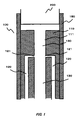
- FIG. 1 is a diagram showing the basic principle of the foamed water generating piece 100 of the present invention.
- FIG. 2 is a diagram schematically showing a state in which foam water is generated by flowing a water flow in the structure shown in FIG.
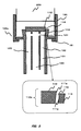
- FIG. 3 is a diagram schematically illustrating a configuration example of the foam water generating piece 100a according to the second embodiment.
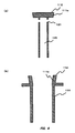
- FIG. 4 is a view taken out so that the shape of the water flow forming component 110a of Example 2 is easily understood.
- FIG. 5 is a diagram schematically showing the generation of foam water by flowing a water flow using the foam water generation piece 100a of the second embodiment.
- FIG. 6 is a diagram schematically showing a configuration example provided with an acceleration water flow driving position variable mechanism.
- FIG. 1 is a diagram showing the basic principle of the foamed water generating piece 100 of the present invention.
- FIG. 2 is a diagram schematically showing a state in which foam water is generated by flowing a water flow in the structure shown in FIG.
- FIG. 3 is
- FIG. 7 is a diagram schematically showing a configuration example provided with an accelerating water flow driving angle variable mechanism.
- FIG. 8 is a diagram schematically showing a configuration example provided with a variable conduction hole width mechanism.
- FIG. 9 is a diagram (part 1) schematically showing a configuration example provided with a ventilation path conduction angle variable mechanism.
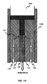
- FIG. 10 is a diagram (No. 2) schematically showing a configuration example including a ventilation path conduction angle variable mechanism.
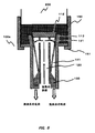
- FIG. 11 is a diagram illustrating a structure example of a foamed water generating piece 100b provided with a water flow speed reducing unit according to the third embodiment.
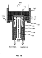
- FIG. 12 is a diagram schematically illustrating a state in which foam water is generated by flowing a water flow in the configuration example according to the third embodiment illustrated in FIG. 11.
- FIG. 1 is a diagram showing the basic principle of a foam water generating piece 100 of the present invention.
- the foamed water generating piece 100 of the present invention is attached to a water discharge pipe 200 such as a water tap and the water discharged from the water discharge pipe 200 is foamed water.
- the foamed water generating piece 100 of the present invention includes a water flow forming component 110, an air passage 120, a water flow passage 130, and an attachment part 150.
- FIG. 1 is a diagram showing the basic principle of a foam water generating piece 100 of the present invention.
- the foamed water generating piece 100 of the present invention is attached to a water discharge pipe 200 such as a water tap and the water discharged from the water discharge pipe 200 is foamed water.
- the foamed water generating piece 100 of the present invention includes a water flow forming component 110, an air passage 120, a water flow passage 130, and an attachment part 150.
- FIG. 1 is a diagram showing the basic principle of a foam water generating piece 100
- the internal structure is shown as a vertical section so that the internal structure can be easily understood.
- the water flow forming component 110 is a portion that forms a water flow that flows in the foam water generating piece 100.
- the water flow forming component 110 includes water flow acceleration means 111 for accelerating the water flow.
- the means for accelerating the water flow is not particularly limited, but the structure example shown in FIG. 1 employs, as an example, a method of increasing the speed of the passing water flow by narrowing the width of the water flow path at the location where the water flow is accelerated. .
- the entire upper surface covers the entire surface of the water faucet, but it is simply a member with a narrow hole in the center, and the hole in the center is the water flow pipe 130.
- the width B of the water flow increased by the water flow acceleration means 111 is made smaller than the water flow width A of the attachment part 150 on the upstream side, and the speed of the water flow is accelerated by narrowing the width of the water flow.
- the shape of the accelerating water flow is launched as a cylindrical shape, but is not limited to a rod shape, and various shapes are possible depending on the shapes of the water flow forming component 110 and the water flow accelerating means 111.
- a water saving effect is also obtained. That is, by reducing the width of the water flow formed by the water flow acceleration means 111 as compared with the width of the upstream water flow path 130, a water saving effect is also obtained as a result.
- the attachment unit 150 is attached to the water discharge pipe 200, is an attachment that connects the water faucet 200 and the water flow forming component 110, and is a cylindrical body that surrounds the water flow forming component 110 inside.
- the inner diameter of the attachment part 150 is substantially the same as the outer diameter of the water discharge pipe 200 of the water tap. That is, it is attached to the water discharge pipe 200.
- a screw for screwing with the water tap 200 is provided.
- the screwing screw is screwed with a male screw provided on the outer periphery of the water discharge pipe 200 of the water tap so as to be screwed without leakage.
- the attachment unit 150 includes a locking portion 151 that locks the mortar-shaped cylindrical body 114 and the edge of the water channel 130 below the mortar-shaped cylindrical body 114. Due to the presence of the locking portion 151, the mortar-shaped cylindrical body 114 and the water flow path 130 below the mortar-shaped cylinder 114 are suspended and fixed to the water tap 200 through the attachment portion 150.
- the air passage 120 is a passage of air that communicates with the outside air, and is provided with a conduction hole 121 on the side wall surface of the water flow tube 130, and is a portion that supplies air from the side wall surface of the water flow tube 130.
- the water flow acceleration means 111 is provided, and the conduction hole 121 is provided in the side wall surface at the location where the speed of the water flow is high. That is, air is supplied from the conduction hole 121 to the accelerated water flow accelerated by the water flow accelerating means 111 and touched, and the air is entrained by the momentum of the accelerated water flow to form foam water.
- FIG. 2 schematically shows how the foamed water is generated by flowing a water flow in the structure shown in FIG. The flow of water flow, the flow of air, and the foamed water formed are shown typically.
- FIG. 3 is a diagram schematically illustrating a configuration example of the foam water generating piece 100a according to the second embodiment.
- the internal structure is shown as a longitudinal sectional view so that the internal structure can be easily understood.
- the rotating body is centered on the vertical axis. As shown in FIG.
- a water flow forming component 110a is formed below the attachment unit 150, and an accelerated water flow is formed by the water flow acceleration means 111a.
- the state of FIG. 3 is a state in which the inverted conical body 112 is fitted into the mortar-shaped cylinder 113 from above.
- the gap 114 between the inner peripheral wall surface of the mortar-shaped cylinder 113 facing the side surface of the inverted conical body 112 is adjusted so as to provide a gap 114 between them instead of fitting them with no gap.
- the gap 114 is formed as a water flow path in the foam water generating piece 100a.
- the reverse cone 112 and the lower air passage 120 are shown slightly lifted from the mortar-shaped cylinder 113, but the reverse cone 112 and the lower air passage 120 are formed by a structure (not shown). It shall be maintained above.
- the attachment unit 150 is attached to the water discharge pipe 200, is an attachment that connects the water faucet 200 and the water flow forming component 110, and is a tube surrounding the water flow forming component 110 inside. It is a body.
- FIG. 4 is a view taken out so that the shape of the water flow forming component 110a of Example 2 is easily understood.
- FIG. 4 shows a longitudinal section, which is actually a rotating body centered on the vertical axis, but only the conduction hole 121 is not a rotating body, and a plurality of holes formed in the side surface of the air passage 120. It has become.
- the water flow acceleration means 111a of the water flow forming component 110a is a combination of the side surface of the inverted cone 112 and the inner peripheral wall surface of the mortar-shaped cylinder 113, and a gap 114 between the two is provided in the foam water generating piece 100a. It is a water flow path.
- FIG. 4A is a view showing the inverted conical body 112 and the vent passage 120 provided below.
- the air passage 120 is a hollow cylindrical body.
- the conduction hole 121 is a hole formed in the side surface of the air passage 120.
- FIG. 4B is a view showing the mortar-shaped cylinder 113 and the water flow path 130 provided below.
- the water channel 130 is a hollow cylindrical body.
- the width of the gap 114 is smaller than the width of the upstream attachment part 150, so that the water flow is accelerated when passing through the gap 114.
- the accelerated water flow formed by the water flow path forming component 110a is launched as a cylindrical shape, that is, a rotating belt.
- the shape of the accelerated water flow is not limited, and various shapes are possible depending on the shape of the water flow acceleration means 111a of the water flow forming component 110a. In this configuration example, as shown in FIG.
- FIG. 5 is a diagram schematically illustrating the generation of foam water by flowing a water flow using the foam water generation piece 100a of the second embodiment.
- a water flow flows from the attachment unit 150 toward the gap 114 of the water flow path forming component 110a, and the water flow is accelerated when passing through the gap 114.
- the accelerated water stream is driven into the air cavity 131.
- the width of the water flow path 130 is wider than the width of the accelerated water flow, air exists inside.
- the accelerating water flow is driven into the air cavity 131 filled with air, and flows downstream while entraining the air. Therefore, the air in the air cavity 131 is flowed and the atmospheric pressure decreases.
- the air hole 131 is provided with the conduction hole 121, the pressure drop also occurs in the vicinity of the conduction hole 121, and the air pressure in the vicinity of the conduction hole 121 is greatly reduced. Since the conduction hole 121 is conducted to the outside air through the air passage 120, the outside air is vigorously sucked into the air cavity 131 through the air passage due to a decrease in the air pressure in the air cavity 131. Although depending on the diameter of the conduction hole 121, when air is drawn in vigorously, the speed of the air flow passing through the conduction hole 121 becomes high. Here, since the acceleration water flow flows in the vicinity of the conduction hole 121, air is driven into the acceleration water flow.
- the air cavity 131 is filled with air, and the acceleration water flow is driven into the air mass vigorously. From the side, air is injected from the conduction hole 121, and the air bubbles are uniformly diffused into the acceleration water flow. As a result, it is possible to produce high-quality foam water.
- FIG. 5 the water hatching after the change to foam water is depicted as a fine hatching compared to the water hatching before the change to foam water.
- the above configuration is a basic configuration example using the air cavity 131.
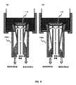
- FIG. 6 is a diagram schematically illustrating a configuration example including an acceleration water flow driving position variable mechanism. Also in FIG.
- the accelerating water flow driving position variable mechanism is a portion that is formed by the water flow forming component 110a, changes the formation position of the accelerated water flow accelerated by the water flow acceleration means 111a, and changes the distance to the conduction hole 121.
- the method of changing the formation position of the acceleration water flow and making the distance to the conduction hole 121 variable is not limited, but in this configuration example, the formation position of the water flow forming part 110a and the water flow acceleration means 111a is changed in the left-right direction by the acceleration water flow driving position variable mechanism. It has a structure that can be moved to.
- the position of the housing forming the gap 114 is changed to the center or the outer periphery as shown by the arrows in the drawing. It has become something that can be.
- the acceleration water flow driving position variable mechanism is adjusted as shown in FIG. 6A to FIG. 6B, the formation position of the acceleration water flow changes to the center side (the one closer to the conduction hole 121), and the distance to the conduction hole 121 is small. Become.
- the acceleration water flow driving position variable mechanism is adjusted as shown in FIG. 6B to FIG.
- the formation position of the acceleration water flow is changed to the outer peripheral side (the one far from the conduction hole 121), and the distance to the conduction hole 121 is changed. Becomes larger.
- the air driven from the conduction hole 121 enters the air cavity 131, it collides with the air in the air cavity 131 and becomes resistance, and the speed of the air decreases as the moving distance in the air cavity increases before being driven into the accelerated water flow.
- the speed and the amount of air driven into the accelerated water flow can be adjusted. As shown in FIG.
- FIG. 7 is a diagram schematically illustrating a configuration example provided with the acceleration water flow driving angle variable mechanism. Also in FIG.
- the accelerating water flow driving angle variable mechanism is a portion that is formed by the water flow forming component 110a, changes the driving angle of the accelerated water flow accelerated by the water flow acceleration means 111a, and makes the distance and angle to the conduction hole 121 variable.
- the method of changing the driving angle of the accelerated water flow and changing the distance and the angle with respect to the conduction hole 121 is not limited, but in this configuration example, the mounting angle of the water flow forming component 110a and the water flow accelerating means 111a is changed by the accelerated water flow driving angle variable mechanism. It has a structure that can be changed.
- the casing forming the conduction hole 121 can be moved up and down as indicated by arrows in the drawing.
- the specific structure of the accelerating water flow driving angle variable mechanism is not shown in the drawing, the inclination angle of the casing forming the gap 114 can be changed as indicated by the arrows in the drawing. Yes.
- the acceleration water flow driving angle variable mechanism is adjusted as shown in FIG. 7A to FIG. 7B, the driving angle of the acceleration water flow changes to the center side (the side closer to the conduction hole 121), and the distance to the conduction hole 121 is small. Become.
- the acceleration water flow driving angle variable mechanism is adjusted as shown in FIG. 7B to FIG.
- the formation position of the acceleration water flow is changed to the outer peripheral side (the one far from the conduction hole 121), and the distance to the conduction hole 121 is changed. Becomes larger.
- the air driven from the conduction hole 121 enters the air cavity 131, the air collides with the air in the air cavity 131, so that resistance becomes greater, and the moving distance in the air cavity 131 becomes longer before being driven into the accelerated water flow.
- the speed of air falls, conversely, by adjusting the moving distance in the air cavity, the speed of air and the amount of air driven into the accelerated water flow can be adjusted. As shown in FIG.
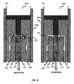
- FIG. 8 is a diagram schematically illustrating a configuration example provided with a variable conduction hole width mechanism.
- Example 1 demonstrates as an example in which the width
- FIG. 8 the water hatching after the change to foam water is depicted as a fine hatching compared to the water hatching before the change to foam water.
- the variable conduction hole width mechanism is a part that changes the width of the conduction hole 121 to vary the speed of the air drawn from the conduction hole 121 and driven into the air cavity.
- the method of making the width of the conduction hole 121 variable is not limited, but in this configuration example, the vertical distance of the parts forming the conduction hole 121 is made variable by the conduction hole width variable mechanism, and the size of the gap between the two is changed. It has a structure that can be changed.
- the casing forming the conduction hole 121 can be moved up and down as indicated by arrows in the drawing.
- the conductive hole width variable mechanism is adjusted as shown in FIG. 8A to FIG. 8B, the width of the conductive hole 121 is widened, and the passage of air drawn from the conductive hole 121 is widened.
- the air pressure in the air cavity 131 decreases, the amount of air drawn is constant, so the speed of the air flow that passes through the conduction hole 121 decreases.
- the conductive hole width variable mechanism is adjusted as shown in FIG. 8B to FIG.
- the width of the conductive hole 121 is narrowed and the passage of air drawn from the conductive hole 121 is narrowed.
- the air pressure in the air cavity 131 is lowered, the amount of air drawn is constant, so that the speed of the air flow passing through the conduction hole 121 increases. That is, the state of FIG. 8A is faster than the state of FIG. 8B, the speed of the air flow driven from the conduction hole 121 is increased, and the speed and amount of the air flow driven into the accelerated water flow are increased. The amount of air bubbles mixed in the accelerated water flow will increase. Conversely, the state of FIG. 8B is slower than the state of FIG.
- the speed of the air flow driven from the conduction hole 121 is reduced, and the speed and amount of the air flow driven into the accelerated water flow are reduced.
- the amount of air bubbles mixed in the accelerated water flow is reduced.
- the amount of air bubbles can be adjusted by adjusting the width of the conduction hole 121 by the conduction hole width variable mechanism. Note that the amount of air bubbles and the size of air bubbles actually mixed into the accelerated water flow depend on various conditions such as the amount of accelerated water flow, the speed of the accelerated water flow, the size and width of the air cavity 131, and the size of the introduction hole 121.
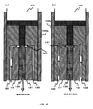
- FIG. 9 is a diagram schematically illustrating a configuration example provided with a ventilation path conduction angle variable mechanism.
- the structural example shown in Example 1 it demonstrates as an example from which the attachment angle of the conduction
- the hatching of the water after the change to foam water is depicted as a fine hatching compared to the hatching of the water before the change to foam water.
- the air passage conduction angle varying mechanism adjusts the angle of the air flow that is driven into the air cavity 131 by changing the attachment angle of the air passage 120 with respect to the water passage 130.
- the method of making the attachment angle of the air passage 120 relative to the water passage 130 variable is not limited, in this configuration example, the angle of the parts forming the air passage 120 is made variable by the air passage conduction angle varying mechanism, and the angle between the gaps between the two. The structure can be changed. In the state of FIG.
- the attachment angle of the air passage 120 with respect to the side wall of the water flow tube is 90 degrees with respect to the direction of the accelerated water flow, and the air particles driven from the conduction holes 121 are substantially the same as the accelerated water flow. It is driven at a right angle.
- the attachment angle of the air passage 120 with respect to the side wall of the water flow pipe is an angle greater than 0 degrees and smaller than 90 degrees (approximately 45 degrees in this example) with respect to the direction of the accelerated water flow.
- air particles driven from the conduction hole 121 are driven at an angle of 45 degrees with respect to the accelerated water flow.
- the attachment angle of the air passage 120 with respect to the side wall of the water flow tube is an angle larger than 90 degrees and smaller than 180 degrees (approximately 135 degrees in this example) with respect to the direction of the accelerated water flow.
- the air particles driven from the conduction hole 121 are driven at an angle of 135 degrees with respect to the accelerated water flow. In this way, by adjusting the angle of the air flow driven into the acceleration water flow, the speed and angle at which the air flow collides with the acceleration water flow changes, and the amount of air bubbles mixed in the acceleration water flow and the air bubbles The size will change.
- the amount of air bubbles and the size of air bubbles actually mixed into the accelerated water flow depend on various conditions such as the amount of accelerated water flow, the speed of the accelerated water flow, the size and width of the air cavity 131, and the size of the introduction hole 121.
- the amount of air bubbles mixed in the accelerated water flow and the size of the air bubbles may be adjusted by changing the conduction angle of the air passage 120 by the air passage conduction angle variable mechanism in consideration of them.
- the foam water generating piece 100b according to the third embodiment includes a water flow decelerating means that is accelerated by the water flow accelerating means and weakens the momentum of the water flow that has become the foam water and leads to the downstream side, and adjusts the speed of the foam water to be discharged. It is.
- FIG. 11 is a diagram illustrating a structure example of the foamed water generating piece 100b including the water flow speed reducing unit according to the third embodiment.
- the structure example shown in FIGS. 3 to 5 of the second embodiment will be described as a structure example provided with the water flow speed reducing means 140.
- the foam water generation piece 100b includes a water flow speed reduction means 140.
- a water flow speed reduction means 140 In FIG. 11, all components of the water flow forming component 110, the water flow accelerating means 111, the air flow channel 120, the water flow channel 130, and the air cavity 131 are all shown in a cross-sectional view so that the structure of each part of the foam water generating piece 100 b can be easily understood. It shows a rotating body rotated about the vertical axis.
- the conduction holes 121 are holes that are appropriately provided in the side wall of the cylindrical water flow path 130 and are not completely rotating bodies.
- the structure of the water flow deceleration means 140 is not particularly limited as long as it is a means for decelerating the water flow, but in this configuration example, it is a diffusion plate.
- the diffusion plate which is the water flow reduction means 140 is a disc body like a truncated cone provided from the inner peripheral wall of the water flow path 130 toward the outer periphery. In this example, in order to reduce the number of parts, it is a structural example formed integrally with the water flow path 130.
- the diffusion plate which is the water flow speed reducing means 140 is provided so as to hit the water flow passing through the water flow path 130. That is, the diffusion plate which is the water flow decelerating means 140 is accelerated by the water flow accelerating means 111 of the upstream water flow forming component 110, passes through the vicinity of the conduction hole 121, and is driven downstream as foam water containing air bubbles. The position and angle are adjusted so that the incoming water stream collides.
- the diffusion plate that is the water flow reduction unit 140 is provided in a slightly oblique direction, and the water flow that has collided with the diffusion plate that is the water flow reduction unit 140 and has been weakened is rebounded to the outer peripheral side, and the water flow reduction unit The structure flows out from the downstream water flow path 130 through a gap 141 around the diffusion plate 140.
- the water flow decelerating means 140 only needs to be able to weaken the momentum of the accelerated water flow, so if the time until the water flow is discharged excessively by weakening the flow excessively, the generated foam water bubbles are reduced in time.
- FIG. 12 is a diagram schematically illustrating a state in which foam water is generated by flowing a water flow in the configuration example according to the third embodiment illustrated in FIG. 11. Compared to the water hatching before the change to foam water, the water hatch after the change to foam water is drawn with fine hatching. As shown in FIG. 5 of the second embodiment, the accelerated water flow accelerated by the water flow acceleration means 110a in the gap 114 between the inverted cone 112 and the mortar-shaped cylinder 113 is driven into the air cavity 131, and the conduction hole 121 is formed.
- Example 3 When passing, air is driven into foamy water.
- the structural example of Example 3 there is a diffuser that is the water flow reduction means 140 at the jet destination of the foam water, and the momentum of the water flow is weakened by colliding with the diffuser.
- the foamed water whose strength is weakened does not stay excessively and flows downstream from the gap between the diffuser, which is the water flow reduction means 140, and the water flow path 130.
- the foamed water is discharged as a gentle water flow.
- generation piece of Example 3 while being able to produce
- the present invention is not limited to water taps for general use, water taps for laboratories, flushing faucets for washing eyes in a pool, showers, etc.
- the water-saving function and the foam function can be applied without being limited to the application. It will be understood that various modifications can be made without departing from the scope of the invention. Therefore, the technical scope of the present invention is limited only by the description of the appended claims.
- the present invention is not limited to its use, as long as water comes out such as a water faucet for a laboratory, a water faucet for washing eyes in a pool, a shower, etc. Can be applied.
Landscapes
- Health & Medical Sciences (AREA)
- Life Sciences & Earth Sciences (AREA)
- Engineering & Computer Science (AREA)
- Hydrology & Water Resources (AREA)
- Public Health (AREA)
- Water Supply & Treatment (AREA)
- Chemical & Material Sciences (AREA)
- Chemical Kinetics & Catalysis (AREA)
- Aeration Devices For Treatment Of Activated Polluted Sludge (AREA)
- Domestic Plumbing Installations (AREA)
- Nozzles (AREA)
Abstract
Priority Applications (12)
| Application Number | Priority Date | Filing Date | Title |
|---|---|---|---|
| US13/260,034 US9297153B2 (en) | 2009-03-26 | 2009-03-26 | Water saving aerator |
| JP2011505794A JP4860781B2 (ja) | 2009-03-26 | 2009-03-26 | 泡沫水生成コマ |
| SG2011069770A SG174924A1 (en) | 2009-03-26 | 2009-03-26 | Foamed-water generating plug |
| EP09842291.8A EP2412877B1 (fr) | 2009-03-26 | 2009-03-26 | Bouchon de génération d'eau moussante |
| PL09842291T PL2412877T3 (pl) | 2009-03-26 | 2009-03-26 | Wkładka wytwarzająca spienioną wodę |
| KR1020117021877A KR101284781B1 (ko) | 2009-03-26 | 2009-03-26 | 거품수 생성 장치 |
| PCT/JP2009/056852 WO2010109680A1 (fr) | 2009-03-26 | 2009-03-26 | Bouchon de génération d'eau moussante |
| ES09842291T ES2715074T3 (es) | 2009-03-26 | 2009-03-26 | Tapón generador de agua con espuma |
| CN200980158172.9A CN102405321B (zh) | 2009-03-26 | 2009-03-26 | 泡沫水生成水塞 |
| DK09842291.8T DK2412877T3 (en) | 2009-03-26 | 2009-03-26 | PROP FOR FORMATION OF FOAMED WATER |
| PT09842291T PT2412877T (pt) | 2009-03-26 | 2009-03-26 | Bocal gerador de água com espuma |
| HUE09842291A HUE043817T2 (hu) | 2009-03-26 | 2009-03-26 | Habosított vizet elõállító eszköz |
Applications Claiming Priority (1)
| Application Number | Priority Date | Filing Date | Title |
|---|---|---|---|
| PCT/JP2009/056852 WO2010109680A1 (fr) | 2009-03-26 | 2009-03-26 | Bouchon de génération d'eau moussante |
Publications (1)
| Publication Number | Publication Date |
|---|---|
| WO2010109680A1 true WO2010109680A1 (fr) | 2010-09-30 |
Family
ID=42780388
Family Applications (1)
| Application Number | Title | Priority Date | Filing Date |
|---|---|---|---|
| PCT/JP2009/056852 Ceased WO2010109680A1 (fr) | 2009-03-26 | 2009-03-26 | Bouchon de génération d'eau moussante |
Country Status (12)
| Country | Link |
|---|---|
| US (1) | US9297153B2 (fr) |
| EP (1) | EP2412877B1 (fr) |
| JP (1) | JP4860781B2 (fr) |
| KR (1) | KR101284781B1 (fr) |
| CN (1) | CN102405321B (fr) |
| DK (1) | DK2412877T3 (fr) |
| ES (1) | ES2715074T3 (fr) |
| HU (1) | HUE043817T2 (fr) |
| PL (1) | PL2412877T3 (fr) |
| PT (1) | PT2412877T (fr) |
| SG (1) | SG174924A1 (fr) |
| WO (1) | WO2010109680A1 (fr) |
Cited By (1)
| Publication number | Priority date | Publication date | Assignee | Title |
|---|---|---|---|---|
| WO2017018119A1 (fr) * | 2015-07-30 | 2017-02-02 | 雅彰 高野 | Dispositif pour générer un fluide pulsatile ou un fluide intermittent |
Families Citing this family (3)
| Publication number | Priority date | Publication date | Assignee | Title |
|---|---|---|---|---|
| US10184233B2 (en) * | 2016-08-28 | 2019-01-22 | Gary Wu | Aerator with LED |
| US10898909B2 (en) * | 2017-10-25 | 2021-01-26 | Pioneer Industries, Inc. | Water pressure boosting device |
| US10953416B2 (en) | 2018-02-13 | 2021-03-23 | Yung-Chieh Tan | Liquid saving device |
Citations (5)
| Publication number | Priority date | Publication date | Assignee | Title |
|---|---|---|---|---|
| JPS5058553U (fr) * | 1973-09-25 | 1975-05-31 | ||
| JPH038940A (ja) * | 1989-06-06 | 1991-01-16 | Toto Ltd | 泡沫吐水口 |
| JPH047051A (ja) * | 1990-04-23 | 1992-01-10 | Toto Ltd | 吐水ヘッド |
| JP2007089710A (ja) * | 2005-09-27 | 2007-04-12 | Matsushita Electric Works Ltd | シャワー装置 |
| JP2008297862A (ja) * | 2007-06-04 | 2008-12-11 | Yoshiki Tatemori | 節水部材及びそれを用いた節水具 |
Family Cites Families (17)
| Publication number | Priority date | Publication date | Assignee | Title |
|---|---|---|---|---|
| GB698691A (en) | 1949-11-29 | 1953-10-21 | Elie Prodromos Aghnides | Mixing devices for liquid and gas |
| DE1038531B (de) * | 1953-08-05 | 1958-09-11 | Rothmayr & Co | Auslauftuelle |
| US3334818A (en) * | 1965-09-22 | 1967-08-08 | Alfred M Moen | Swivel spray aerators |
| US3712548A (en) * | 1970-08-20 | 1973-01-23 | E Aghnides | Water aerator |
| JPS5058553A (fr) * | 1973-09-21 | 1975-05-21 | ||
| US4153204A (en) | 1975-08-08 | 1979-05-08 | Aghnides Elie P | Aerator with metal casing having inner plastic elements moldable in one piece |
| US4322292A (en) * | 1981-01-02 | 1982-03-30 | Rjd | Aerator |
| US4484710A (en) * | 1983-03-11 | 1984-11-27 | The United States Of America As Represented By The Secretary Of The Army | Fire suppressant nozzle |
| US4869103A (en) * | 1988-06-03 | 1989-09-26 | Jerman James K | Water flow measuring and dispersing device |
| JPH0679684B2 (ja) | 1989-11-21 | 1994-10-12 | 東陶機器株式会社 | 泡沫吐水口 |
| KR970002860B1 (ko) * | 1989-11-21 | 1997-03-12 | 도오 또오 기끼 가부시끼가이샤 | 포말토수장치 |
| US5826799A (en) * | 1996-12-03 | 1998-10-27 | Hsieh; Paul | Sprinkling head structure |
| KR100243787B1 (ko) * | 1997-03-31 | 2000-02-01 | 전주범 | 에어버블 발생장치 |
| IT1293138B1 (it) * | 1997-06-03 | 1999-02-12 | Gevipi Ag | Dispositivo per l'aereazione di una doccia a getti multipli. |
| CN2705681Y (zh) * | 2004-01-20 | 2005-06-22 | 招丽恩 | 一种节水嘴芯 |
| US7611070B2 (en) * | 2006-02-28 | 2009-11-03 | Paoluccio John J | Aspirating scented oxygen enriched faucet and shower head |
| JP4369993B1 (ja) * | 2008-10-31 | 2009-11-25 | 雅彰 高野 | 節水コマ |
-
2009
- 2009-03-26 PL PL09842291T patent/PL2412877T3/pl unknown
- 2009-03-26 PT PT09842291T patent/PT2412877T/pt unknown
- 2009-03-26 ES ES09842291T patent/ES2715074T3/es active Active
- 2009-03-26 HU HUE09842291A patent/HUE043817T2/hu unknown
- 2009-03-26 EP EP09842291.8A patent/EP2412877B1/fr active Active
- 2009-03-26 US US13/260,034 patent/US9297153B2/en active Active
- 2009-03-26 SG SG2011069770A patent/SG174924A1/en unknown
- 2009-03-26 JP JP2011505794A patent/JP4860781B2/ja active Active
- 2009-03-26 CN CN200980158172.9A patent/CN102405321B/zh active Active
- 2009-03-26 KR KR1020117021877A patent/KR101284781B1/ko active Active
- 2009-03-26 DK DK09842291.8T patent/DK2412877T3/en active
- 2009-03-26 WO PCT/JP2009/056852 patent/WO2010109680A1/fr not_active Ceased
Patent Citations (5)
| Publication number | Priority date | Publication date | Assignee | Title |
|---|---|---|---|---|
| JPS5058553U (fr) * | 1973-09-25 | 1975-05-31 | ||
| JPH038940A (ja) * | 1989-06-06 | 1991-01-16 | Toto Ltd | 泡沫吐水口 |
| JPH047051A (ja) * | 1990-04-23 | 1992-01-10 | Toto Ltd | 吐水ヘッド |
| JP2007089710A (ja) * | 2005-09-27 | 2007-04-12 | Matsushita Electric Works Ltd | シャワー装置 |
| JP2008297862A (ja) * | 2007-06-04 | 2008-12-11 | Yoshiki Tatemori | 節水部材及びそれを用いた節水具 |
Cited By (5)
| Publication number | Priority date | Publication date | Assignee | Title |
|---|---|---|---|---|
| WO2017018119A1 (fr) * | 2015-07-30 | 2017-02-02 | 雅彰 高野 | Dispositif pour générer un fluide pulsatile ou un fluide intermittent |
| CN107921447A (zh) * | 2015-07-30 | 2018-04-17 | 高野雅彰 | 脉动流体或断续流体的生成装置 |
| EP3330005A4 (fr) * | 2015-07-30 | 2018-07-25 | Masaaki Takano | Dispositif pour générer un fluide pulsatile ou un fluide intermittent |
| CN107921447B (zh) * | 2015-07-30 | 2020-04-07 | 高野雅彰 | 脉动流体或断续流体的生成装置 |
| US11097287B2 (en) | 2015-07-30 | 2021-08-24 | Masaaki Takano | Device for generating pulsatile flow or intermittent flow |
Also Published As
| Publication number | Publication date |
|---|---|
| CN102405321B (zh) | 2015-05-20 |
| JPWO2010109680A1 (ja) | 2012-09-27 |
| KR20120024536A (ko) | 2012-03-14 |
| KR101284781B1 (ko) | 2013-07-17 |
| SG174924A1 (en) | 2011-11-28 |
| EP2412877A4 (fr) | 2014-11-19 |
| US20120024984A1 (en) | 2012-02-02 |
| ES2715074T3 (es) | 2019-05-31 |
| PL2412877T3 (pl) | 2019-07-31 |
| EP2412877A1 (fr) | 2012-02-01 |
| HUE043817T2 (hu) | 2019-09-30 |
| JP4860781B2 (ja) | 2012-01-25 |
| DK2412877T3 (en) | 2019-04-01 |
| EP2412877B1 (fr) | 2018-12-12 |
| PT2412877T (pt) | 2019-03-22 |
| CN102405321A (zh) | 2012-04-04 |
| US9297153B2 (en) | 2016-03-29 |
Similar Documents
| Publication | Publication Date | Title |
|---|---|---|
| KR101697840B1 (ko) | 샤워기 변기를 위한 샤워기 암 | |
| CN110446547B (zh) | 微气泡发生装置以及淋浴喷头 | |
| JP4860781B2 (ja) | 泡沫水生成コマ | |
| JP4369993B1 (ja) | 節水コマ | |
| CN103221618B (zh) | 泡沫水产生栓 | |
| JP2008303616A (ja) | 水洗便器のリム吐出口構造 | |
| JP5800276B2 (ja) | 吐水装置 | |
| JP2012072594A (ja) | 泡沫吐水装置 | |
| JP5762422B2 (ja) | 節水コマ | |
| JP5276254B2 (ja) | 水洗便器装置 | |
| JP5660281B2 (ja) | 吐水装置 | |
| JPH0363333A (ja) | 泡沫吐水口 | |
| JP5762425B2 (ja) | 節水コマ | |
| JPH03161063A (ja) | 泡沫吐水口 | |
| EE202200013A (et) | Volkovi kavitatsiooni aeraator | |
| KR101490817B1 (ko) | 버블 샤워기 | |
| JP6315247B2 (ja) | 吐水装置 | |
| JP6315249B2 (ja) | 吐水装置 | |
| CN116517084A (zh) | 马桶主体及马桶 | |
| CN121110788A (zh) | 冲刷喷头及马桶 | |
| JP2002079067A (ja) | 気泡流吐出装置 | |
| WO2010109679A1 (fr) | Bouchon d'économie d'eau | |
| JP2012235951A (ja) | 気泡発生装置 | |
| HK1183076B (en) | Foamed-water generating plug | |
| JPH03231673A (ja) | 気泡噴出装置 |
Legal Events
| Date | Code | Title | Description |
|---|---|---|---|
| WWE | Wipo information: entry into national phase |
Ref document number: 200980158172.9 Country of ref document: CN |
|
| 121 | Ep: the epo has been informed by wipo that ep was designated in this application |
Ref document number: 09842291 Country of ref document: EP Kind code of ref document: A1 |
|
| WWE | Wipo information: entry into national phase |
Ref document number: 2011505794 Country of ref document: JP |
|
| ENP | Entry into the national phase |
Ref document number: 20117021877 Country of ref document: KR Kind code of ref document: A |
|
| NENP | Non-entry into the national phase |
Ref country code: DE |
|
| WWE | Wipo information: entry into national phase |
Ref document number: 13260034 Country of ref document: US |
|
| WWE | Wipo information: entry into national phase |
Ref document number: 2009842291 Country of ref document: EP |