WO2017018119A1 - Dispositif pour générer un fluide pulsatile ou un fluide intermittent - Google Patents
Dispositif pour générer un fluide pulsatile ou un fluide intermittent Download PDFInfo
- Publication number
- WO2017018119A1 WO2017018119A1 PCT/JP2016/069300 JP2016069300W WO2017018119A1 WO 2017018119 A1 WO2017018119 A1 WO 2017018119A1 JP 2016069300 W JP2016069300 W JP 2016069300W WO 2017018119 A1 WO2017018119 A1 WO 2017018119A1
- Authority
- WO
- WIPO (PCT)
- Prior art keywords
- fluid
- intermittent
- pulsating
- flow
- outside air
- Prior art date
- Legal status (The legal status is an assumption and is not a legal conclusion. Google has not performed a legal analysis and makes no representation as to the accuracy of the status listed.)
- Ceased
Links
Images







Classifications
-
- B—PERFORMING OPERATIONS; TRANSPORTING
- B05—SPRAYING OR ATOMISING IN GENERAL; APPLYING FLUENT MATERIALS TO SURFACES, IN GENERAL
- B05B—SPRAYING APPARATUS; ATOMISING APPARATUS; NOZZLES
- B05B1/00—Nozzles, spray heads or other outlets, with or without auxiliary devices such as valves, heating means
- B05B1/02—Nozzles, spray heads or other outlets, with or without auxiliary devices such as valves, heating means designed to produce a jet, spray, or other discharge of particular shape or nature, e.g. in single drops, or having an outlet of particular shape
- B05B1/08—Nozzles, spray heads or other outlets, with or without auxiliary devices such as valves, heating means designed to produce a jet, spray, or other discharge of particular shape or nature, e.g. in single drops, or having an outlet of particular shape of pulsating nature, e.g. delivering liquid in successive separate quantities
-
- B—PERFORMING OPERATIONS; TRANSPORTING
- B05—SPRAYING OR ATOMISING IN GENERAL; APPLYING FLUENT MATERIALS TO SURFACES, IN GENERAL
- B05B—SPRAYING APPARATUS; ATOMISING APPARATUS; NOZZLES
- B05B12/00—Arrangements for controlling delivery; Arrangements for controlling the spray area
- B05B12/02—Arrangements for controlling delivery; Arrangements for controlling the spray area for controlling time, or sequence, of delivery
- B05B12/06—Arrangements for controlling delivery; Arrangements for controlling the spray area for controlling time, or sequence, of delivery for effecting pulsating flow
-
- B—PERFORMING OPERATIONS; TRANSPORTING
- B05—SPRAYING OR ATOMISING IN GENERAL; APPLYING FLUENT MATERIALS TO SURFACES, IN GENERAL
- B05B—SPRAYING APPARATUS; ATOMISING APPARATUS; NOZZLES
- B05B7/00—Spraying apparatus for discharge of liquids or other fluent materials from two or more sources, e.g. of liquid and air, of powder and gas
- B05B7/02—Spray pistols; Apparatus for discharge
- B05B7/04—Spray pistols; Apparatus for discharge with arrangements for mixing liquids or other fluent materials before discharge
- B05B7/0416—Spray pistols; Apparatus for discharge with arrangements for mixing liquids or other fluent materials before discharge with arrangements for mixing one gas and one liquid
- B05B7/0425—Spray pistols; Apparatus for discharge with arrangements for mixing liquids or other fluent materials before discharge with arrangements for mixing one gas and one liquid without any source of compressed gas, e.g. the air being sucked by the pressurised liquid
-
- B—PERFORMING OPERATIONS; TRANSPORTING
- B08—CLEANING
- B08B—CLEANING IN GENERAL; PREVENTION OF FOULING IN GENERAL
- B08B3/00—Cleaning by methods involving the use or presence of liquid or steam
- B08B3/02—Cleaning by the force of jets or sprays
-
- E—FIXED CONSTRUCTIONS
- E03—WATER SUPPLY; SEWERAGE
- E03C—DOMESTIC PLUMBING INSTALLATIONS FOR FRESH WATER OR WASTE WATER; SINKS
- E03C1/00—Domestic plumbing installations for fresh water or waste water; Sinks
- E03C1/02—Plumbing installations for fresh water
- E03C1/08—Jet regulators or jet guides, e.g. anti-splash devices
- E03C1/084—Jet regulators with aerating means
-
- A—HUMAN NECESSITIES
- A61—MEDICAL OR VETERINARY SCIENCE; HYGIENE
- A61H—PHYSICAL THERAPY APPARATUS, e.g. DEVICES FOR LOCATING OR STIMULATING REFLEX POINTS IN THE BODY; ARTIFICIAL RESPIRATION; MASSAGE; BATHING DEVICES FOR SPECIAL THERAPEUTIC OR HYGIENIC PURPOSES OR SPECIFIC PARTS OF THE BODY
- A61H33/00—Bathing devices for special therapeutic or hygienic purposes
- A61H33/02—Bathing devices for use with gas-containing liquid, or liquid in which gas is led or generated, e.g. carbon dioxide baths
- A61H2033/022—Bathing devices for use with gas-containing liquid, or liquid in which gas is led or generated, e.g. carbon dioxide baths with control means for regulating the air volume aspirated by a water jet
Definitions
- the present invention relates to an apparatus for generating a pulsating fluid or an intermittent fluid from a liquid or gas continuous fluid.
- the fluid is not limited to water, and various liquids and gases can be targeted.
- liquids and gases as fluids is required in various devices.
- Water and gas fluids are widely used in homes and offices through water pipes and gas pipes.
- various liquid fluids and gas fluids are used in various devices. It is used in etc.
- Foam water suitable for washing is required for washing hands and dishes. Foamed water is used because it has a gentle touch when washing hands, and since it is a gentle water flow even when washing glass and ceramics, there is no risk of damaging the glass and ceramics. In addition, foamed water does not rebound even if it hits glass or ceramics during cleaning, and there is no risk of splashing water or affecting the surrounding environment, so not only ordinary households but also stations and public facilities Widely used, such as water faucets in research laboratories and water faucets in laboratory laboratories.
- FIG. 16 is a diagram showing the state of cleaning using conventional continuous water in an easy-to-understand manner.
- the water dropped from the tap to the surface of the object is continuous, so the water that reaches the surface of the object diffuses along the surface of the object. Therefore, as shown in FIGS. 16 (b) and 16 (c), there is a situation where water falling in the space slightly above the object surface collides with water bounced off the object surface and cancels out the momentum. appear. For this reason, a water film is formed on the surface of the object, and the surface tension works. Therefore, as shown in FIG.
- the flowing water that has flowed continuously from the top has its momentum offset by the bounced water, and moves laterally so as to slide over the raised water film.
- the proportion of tap water directly against dirt decreases, and the proportion of escape to the side increases. That is, of the water used for cleaning, the ratio of the cleaning water that directly contacts the dirt and pushes the dirt is small, and as shown in FIG. It moves to slide on the formed water film.
- the ratio of the cleaning water that directly contacts the dirt and pushes the dirt is increased, and the cleaning water that moves so as to slide on the water film formed on the dirt.
- the problem is to reduce the proportion and form wash water suitable for washing.
- a technology for forming a pulsating flow or an intermittent flow in a device from a continuous fluid is required not only for cleaning water flow but also in various technical fields. I can give you an example, but I'll give you an example.
- a pulsating flow or an intermittent flow For example, in the field of processing technology, it is necessary to form a pulsating flow or an intermittent flow.
- formation of a pulsating flow or an intermittent flow is required.
- the carrier fluid includes an inert gas.
- a pulsating or intermittent flow medium is used for cleaning or removing unnecessary materials, and a pulsating or intermittent flow medium is used to remove cutting residue and cullet generated during the manufacturing process.
- a technique of hitting it there is a demand for how to simplify the apparatus and reduce the electric driving elements even when forming a pulsating flow or an intermittent flow.
- pulsating flow and intermittent flow are required in measurement technology and measurement technology.
- pulsating flow is used in a microfluidic device such as an automatic reaction device for histochemistry, but it is required to simplify the device and reduce electric driving elements when forming a pulsating flow or an intermittent flow. ing.
- An object of the present invention is to provide various apparatuses in various technical fields as a technique for generating a pulsating flow or an intermittent flow from a continuous fluid.
- a pulsating fluid or intermittent fluid generating device includes an injection mechanism for injecting a liquid or gas fluid, and a closed space located downstream of the injection mechanism, In a configuration including a fluid discharge portion below, a conduction hole connected to a ventilation passage for conducting outside air on its side surface, and a space cavity filled with outside air inside, a jet destination of the jet fluid of the jet mechanism or Due to the change caused by the collision of the jet fluid on the wall surface of the air cavity, a part of the jet fluid flows downward while temporarily covering or giving up the conduction hole, thereby restricting the amount of outside air from the conduction hole.
- the fluid discharge portion has a diameter and a shape in which the fluid is discharged while the entire surface is covered by the jet fluid ejected from the jet mechanism, and the outside air does not flow backward from below. This is because the backflow of the outside air from the fluid discharge portion is eliminated, and the repeated fluctuations of the pressure drop and the pressure recovery in the space cavity become sharp without being dull.
- the jet fluid flows along the front surface of the conduction hole and instantaneously completely blocks the front surface of the conduction hole.
- the pressure drop increases, the outside air is blown from the conduction hole and the force is increased to break the jet fluid.
- This is a pattern in which the so-called ventilation of the outside air and the on / off of the breakage of the jet fluid are repeated.
- the second pattern is a pattern in which the space between the jet fluid and the front surface of the conduction hole is not completely closed and there is a small gap, and there is ventilation through the small gap, but the amount of ventilation is controlled. is there.
- the amount of outside air is controlled by collision between the outside air and the jetting fluid or the jetting splash near the conduction hole.
- the pulsating fluid or intermittent fluid generated by the pulsating fluid or intermittent fluid generating device is, for example, a substantially ball-shaped liquid mass, and the liquid mass is in an intermittent state or some edges are connected to each other. In this state, the ink is discharged in a continuous state. In this way, the continuous fluid can be made into an approximately ball-shaped liquid mass, and the liquid mass can be discharged intermittently or continuously.
- the continuous fluid can be made into an approximately ball-shaped liquid mass, and the liquid mass can be discharged intermittently or continuously.
- the main body structure through which the fluid flows is provided with an outer body that surrounds the outside. Since a ventilation path is formed by the gap provided in the main body structure and the outer body, the flow rate of the intake air becomes faster and the outside air flows toward the conduction hole than when the conduction hole is simply opened to the outside air. Momentum is gained.
- the space cavity is provided as a passage for the jet water flow, and the only thing that flows into the system is the jet water flow through the jet mechanism and the outside air through the conduction hole
- the only thing that flows out of the system is the pulsating fluid or intermittent fluid from the fluid discharge part, and there is no other inflow or outflow in the interstitial cavity, and it is sealed even when the jet water flow is flowing Thus, the state filled with air is maintained.
- the pulsating fluid or intermittent fluid generating device having the above-described configuration includes a plurality of sets, each fluid discharge portion being disposed at a predetermined interval, and each pulsating fluid or intermittent fluid emitted from each fluid discharge portion. It can also be set as the production
- a pulsating flow or intermittent fluid can be formed.
- a foamed water generating piece attached to a water tap it is possible to generate pulsating water flow or intermittent water flow cleaning water having an excellent cleaning effect.
- it can be incorporated into various water flow utilization devices.
- the carrier fluid can be used as an apparatus for making the carrier fluid a pulsating flow or an intermittent flow when introducing the starting compound into the reaction chamber using the carrier fluid.
- the carrier fluid includes an inert gas.
- it can be incorporated into an apparatus for forming a water flow as a pulsating flow or an intermittent flow in water jet peening on the surface of a metal structural member.
- it can be incorporated into various processing devices. It is also demanded as a cleaning technique and removal technique. Instead of a conventional scraper, it can be incorporated into a device for cleaning or removing unnecessary materials using a medium of pulsating flow or intermittent flow, or a device for removing cutting residue and cullet generated in the manufacturing process.
- it can be incorporated into various mechanical devices. Further, it can be incorporated into a measuring device or a measuring device.
- a device for analyzing the influence of a flow of a gas medium or a liquid medium in a test system and a measuring device for forming a pulsating flow of a medium in order to simulate the influence of the pulsating flow.
- it can be incorporated into various measuring devices and measuring devices.
- in order to raise the combustion efficiency of gas it can incorporate in the apparatus which produces
- it can be incorporated into various gas utilization devices.
- it can be incorporated as a pulsating flow generator in a microfluidic device such as a medical device or an automatic reaction device for histochemistry.
- it can be incorporated into various medical devices.
- FIG. 1 It is a figure which shows one structural example of the production
- FIG. 1 It is a figure which shows one structural example of the production apparatus 100a of the pulsating fluid or intermittent fluid of this invention concerning Example 2 of this invention. It is a figure which shows the state which sent the water flow through the production
- FIG. 1 It is a figure which shows simply the state which supplied water from the water supply apparatus with respect to the production
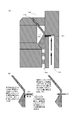
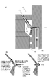
- FIG. 1 is a diagram illustrating a configuration example of a pulsating fluid or intermittent fluid generation apparatus 100 according to a first embodiment of the present invention.
- FIG. 1 shows only a part of the pulsating fluid or intermittent fluid generating device 100 taken out.
- an injection mechanism 110, a space cavity 120, a continuous fluid pipe 130, a ventilation path 140 and a conduction hole 141, and a discharge unit 150 for pulsating fluid or intermittent fluid are illustrated.
- the liquid introduction pipe 130 is a pipe connected to a continuous fluid liquid supply device, which receives the continuous fluid and draws it downward.
- a continuous fluid liquid supply device which receives the continuous fluid and draws it downward.
- FIG. 1 it is depicted as a space above the ejection mechanism 110, but it is a conduit that connects between the liquid supply source and the ejection mechanism 110.
- the liquid supply device and its attachment member are not shown.
- the injection mechanism 110 is a mechanism that injects vigorously as an injection liquid flow by narrowing the area through which the continuous water flow passes.
- it is a member that is provided on the lower surface of the liquid introduction pipe 130, receives a continuous fluid from the liquid introduction pipe 130, narrows the diameter, and jets downward.
- the injection angle of the injection mechanism 110 is an angle at which the injection destination or the sprayed droplet abuts the conduction hole 141 or the vicinity thereof, and a part of the injection mechanism 110 covers the side wall surface including the conduction hole 141 while rebounding and becomes a water flow that flows downward. It has become.
- the space cavity 120 has an injection mechanism 110 disposed on the upper surface, a pulsating fluid or intermittent fluid discharge portion 150 disposed on the lower surface, and forms a sealed space filled with gas flowing in from the conduction hole 141 inside. It is.
- the inflow and outflow to the space cavity 120 are nothing but the inflow of the injection fluid from the injection mechanism 110, the inflow of outside air from the conduction hole 141, and the outflow of pulsating fluid or intermittent fluid from the discharge unit 150, and the others are closed. And airtightness is maintained.
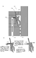
- FIG. 2 is a diagram simply showing a state in which a liquid is supplied from the liquid supply device and a continuous fluid is supplied to the pulsating fluid or intermittent fluid generation device 100 shown in FIG.
- the injection fluid flows in from the injection mechanism 110 into the space cavity 120 where the airtightness is maintained, and from the discharge unit 150 while entraining the gas inside the space cavity 120. Water is flowing out.
- the jet fluid that has flowed in from the jet mechanism 110 is discharged from the discharge unit 150 while entraining and flowing air inside the space cavity 120, so that the atmospheric pressure in the space cavity 120 is lowered. Therefore, outside air is blown from the ventilation path 140 through the conduction hole 141 at a high speed as the atmospheric pressure decreases.
- the ejection destination or ejection splash destination of the ejection fluid comes into contact with the conduction hole 141 or the vicinity thereof, and a part of the ejection mechanism 110 is a water flow that flows downward while covering the side wall surface including the conduction hole 141 while rebounding. It is an angle.
- the spray destination or spray destination of the jet fluid is slightly above the conduction hole 141.
- the jetted fluid hits the side wall surface of the space cavity 120, it is reflected and spreads, but a part of it flows along the side wall surface of the space cavity 120. Since the conduction hole 141 is included in the side wall surface of the space cavity 120, the state where the opening of the conduction hole 141 is sealed with the jet fluid flowing downward appears as shown in FIG.
- the air pressure in the space cavity 120 is lowered when the jet fluid flows downward in the space cavity 120 while entraining and pushing out the air inside. It will be understood that the gas is pushed out together with the jet fluid from the space cavity 120 and the air pressure in the narrow space cavity 120 decreases.
- outside air is blown from the conduction hole 141 into the space cavity 120 through the ventilation path 140.
- This blowing of outside air is caused by a decrease in the atmospheric pressure in the space cavity 120.
- the reduced pressure in the space cavity 120 is recovered.
- the pressure drop and the pressure recovery do not maintain an orderly balanced state, and there is a liquid flow film of the ejected fluid blocking the opening of the conduction hole 141, so the state shown on the left and right in FIG. It will be repeated alternately.
- FIG. 2B is a state in which the opening of the conduction hole 141 is sealed with a liquid flow film formed by a jet fluid. In this state, the blowing of outside air from the conduction hole 141 is instantaneously stopped, the air is pushed out from the space cavity 120, and the pressure in the space cavity 120 that is narrowly sealed decreases.
- the state on the right side of FIG. 2B is a liquid that seals the opening of the conduction hole 141 as a result of an increase in the atmospheric pressure drop in the space cavity 120 and an increase in the pulling force of outside air into the space cavity 120.
- This is a state where the flow film is overcome, the liquid flow film is cut, and the outside air is blown into the space cavity 120.
- the liquid flow film of the ejected fluid is momentarily interrupted, and the outside air blown from the conduction hole 141 is sandwiched, and the atmospheric pressure in the space cavity 120 is recovered by blowing the outside air.
- the force of the outside air drawn into the space cavity 120 becomes smaller, and the momentum of the liquid flow film flowing along the opening of the conduction hole 141 eventually increases, and the opening of the conduction hole 141 is improved. Is returned to the state on the left side of FIG. As described above, the strength of the external air blowing is increased or decreased due to the repeated fluctuation between the atmospheric pressure lowering progress state where the outside air is not blown on the left side in FIG. A rhythm is generated, and pulsating flow or intermittent flow of foam water is generated from the jet fluid.
- the liquid flow film by the jet fluid flows along the front surface of the conduction hole 141.
- the structure may be such that the amount of air flow is limited although there is air flow through the small gap. This case will be described in the second embodiment.
- the liquid passing through the space cavity 120 is mixed with the outside air, and is in the form of foam. It can change to an open air mixture.
- the jet fluid is broken or thinned by the outside air.
- the jetting fluid passing therethrough can be a pulsating flow or a pulsed foam liquid mass intermittently interrupted.
- the shape of the ejected fluid itself is originally ejected as a thin liquid film, the flow of outside air blown into the ejected fluid is repeated, and a break is likely to form and a liquid mass is easily formed.
- the generated liquid mass reaches the entrance of the drainage channel 150 toward the downstream while entraining and flowing the gas in the space cavity 120, but the air pressure in the space cavity 120 repeatedly increases and decreases during that time.
- the pressure in the cavity 120 is relatively strong, the foam liquid mass easily pushes the gas near the drainage channel 150 into the drainage channel 150, and the gas pushed by the liquid mass may be pushed into the drainage channel 150 as a gas mass. obtain.
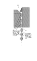
- FIG. 3 illustrates the vicinity of the discharge unit 150 so that the liquid mass and the gas mass flowing through the discharge unit 150 can be easily understood.
- the gas mass is pushed into the tip of the liquid mass. If a gas mass exists between the liquid masses in this way, the preceding liquid mass and the subsequent liquid mass are independent, and the gas mass enters between them, and the discharge unit 150 is formed as a pulsating flow or a pulsed intermittent flow. Will be released out of the system.
- the foam water is illustrated as being completely independent liquid masses in the discharge unit 150 one by one. May occur or a continuous liquid mass may be formed in which the liquid mass behind and the edges are connected to each other, but in any case, it may be a pulsating flow or an intermittent flow instead of a uniform continuous fluid.
- FIG. 4 is a diagram for simply explaining the cleaning effect when the pulsating fluid or intermittent fluid generated by the pulsating fluid or intermittent fluid generating device 100 of the present invention is water and used for cleaning applications.
- the moment is cut out and illustrated, and the fact that it continuously hits as a foamy liquid mass is emphasized.
- FIG. 4 (a) shows a state in which the pulsating fluid or intermittent fluid bubble water flow generated by the pulsating fluid or intermittent fluid generating device 100 of the present invention starts to hit the dirt on the surface of the object.
- an independent liquid mass starts to hit among the pulsating fluid or the intermittent fluid flowing down at high speed.
- FIG. 4 (b) shows a state where the first foam liquid mass hits the dirt, and the foam liquid mass is crushed as it is and the energy of the foam liquid mass is absorbed by the dirt.
- One of the independent foam masses hits the dirt and pushes it laterally so that it crushes without splashing.
- FIG. 4 (c) is a diagram showing a state in which the first foam liquid mass that has arrived next starts to hit.
- FIG. 4D shows a state in which the subsequent foam liquid mass hits the dirt, and the foam liquid mass is crushed as it is and the energy of the foam liquid mass is absorbed by the dirt.
- the preceding foam liquid mass exists in contact with the dirt, but since it is foam water, a water film that swells is not formed, and the upper surface of the dirt is almost bare. Subsequent foam liquid mass hits against this dirt, hits the dirt so that it crushes without splashing, and pushes the dirt further in the lateral direction.
- FIG. 4 (e) is a diagram showing how the first foam liquid mass that comes next starts to hit
- FIG. 4 (f) shows the energy of the foam liquid mass as the subsequent foam liquid mass hits the dirt and the foam liquid mass collapses as it is. Is absorbed by dirt. The dirt is further spread laterally than in the state of FIG. As the independent foam liquid mass continues to hit the dirt in this manner, the dirt is efficiently washed away in the lateral direction. Since it is foam water, there is no water film that is swelled by the preceding foam liquid mass, and the upper surface of the dirt is always close to bareness, and the foam liquid mass that comes one after another hits the dirt directly The energy of the foam liquid mass continues to be applied to the soil. Thus, the foam water flow produced
- FIG. 5 is a diagram showing a state of cleaning with a conventional simple continuous water flow.
- FIG. 5A is a diagram illustrating a state in which a continuous water flow starts to hit the dirt on the object surface.
- FIG. 5 (b) is a diagram showing the moment immediately after the continuous water flow hits the dirt on the object surface. As shown in FIG. 5 (b), a part of the continuous water stream that hits the soil bounces upward, collides with the subsequent continuous water stream, and the momentum cancels out. Moreover, splashes are easily scattered around.
- FIG. 5 (c) is a diagram showing the next stage of FIG. 5 (b).
- the bounce of the water stream that hits the dirt continues, and the momentum of the water stream continues to offset.
- there are many splashes of the surrounding splashes and a water film starts to be formed on the dirt.
- FIG.5 (d) is a figure which shows the next stage of FIG.5 (c).
- the bounce of the water stream that hits the dirt continues, and the momentum of the water stream continues to offset.
- a water film is formed on the dirt, and a part of the continuous water flow easily flows in the lateral direction so as to slide on the water film.
- FIG. 5 (e) is a diagram showing the next stage of FIG. 5 (d).
- the bounce of the water stream that hits the dirt continues, and the momentum of the water stream continues to offset.
- a water film is formed on the dirt, and a part of the continuous water flow slides on the water film so that the dirt is hidden under the water film.
- the state of FIG. 5 (e) is maintained thereafter.
- the high cleaning effect of the foam water flow generated by the pulsating fluid or intermittent fluid generation device 100 of the present invention shown in FIG. 4 is understood.
- the pulsating fluid or intermittent fluid is generated from the continuous fluid by applying the first principle of the pulsating fluid or intermittent fluid generating device.
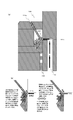
- the injection angle of the injection mechanism 110a is an angle that is ejected at a substantially parallel or slight angle with respect to the side wall surface provided with the conduction hole 141a.
- the conduction hole 141 is provided in the side wall surface facing the injection destination of the injection mechanism 110.
- the injection mechanism 110a is provided in the configuration example of the second embodiment.
- the conduction hole 141 is provided on the side wall surface substantially parallel to the injection destination.
- FIG. 7 is a diagram simply showing a state in which the liquid is supplied from the liquid supply device and the jet fluid is allowed to flow with respect to the pulsating fluid or intermittent fluid generation device 100a shown in FIG.
- a water flow vigorously flows from the injection mechanism 110a into the space cavity 120 where airtightness is maintained, and water flows out from the discharge unit 150 while entraining the internal gas.
- the points to be followed are the same as in the first embodiment.
- the jet fluid that has flowed in from the jet mechanism 110a is discharged from the discharge unit 150 while entraining and pushing the air inside the space cavity 120, so that the atmospheric pressure in the space cavity 120 is lowered. Therefore, the outside air is blown from the air passage 140a at high speed through the conduction hole 141a as the atmospheric pressure decreases.
- FIG. 7 illustrates a state in which part of the jet fluid flows in a direction along the side wall surface due to the influence of diffraction, surface tension, and the like near the side wall surface of the space cavity 120. As shown in FIG. 7, the state where the opening of the conduction hole 141a is sealed with the jet fluid flowing downward appears.
- the air pressure in the space cavity 120 may be lowered by causing the jet fluid to flow downward while entraining and pushing out the air inside the space cavity 120. It will be understood that, depending on the shape and momentum of the jet fluid, gas is pushed downward from the space cavity 120 and the air pressure in the narrow space cavity 120 decreases.
- outside air is blown from the conduction hole 141 a into the space cavity 120 through the ventilation path 140.
- This blowing of outside air is caused by a decrease in the atmospheric pressure in the space cavity 120.
- the reduced pressure in the space cavity 120 is recovered.
- the state shown on the left and right in FIG. 7B is alternately repeated.
- the state on the right side of FIG. 7B is a liquid that seals the opening of the conduction hole 141a as a result of a decrease in the atmospheric pressure in the space cavity 120 and a greater force for drawing outside air into the space cavity 120.
- This is a state where the flow film is overcome, the liquid flow film is cut, and the outside air is blown into the space cavity 120.
- the fluid film of the jet fluid is momentarily interrupted, and the outside air blown from the conduction hole 141a is sandwiched, and the atmospheric pressure in the space cavity 120 is recovered by blowing the outside air.
- the jet fluid does not flow completely along the front surface of the conduction hole and does not completely block it, but the liquid flow film flows so as to give up the front surface of the conduction hole and there is a slight gap.
- the structure may be such that the amount of air flow is limited although there is air flow through the small gap.
- the jet fluid from the jet mechanism 110 a collides with the wall surface of the air cavity 120, and the size of the internal air cavity 120 is not excessively large and is jetted depending on the condition of the shape and angle of the wall surface. It is possible for the fluid to reflect vigorously and scatter.
- the splashed spray droplets may cover the conduction hole 141a.
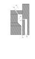
- FIG. 9 is a diagram simply illustrating a configuration example of the pulsating fluid or intermittent fluid generating device 100b according to the third embodiment of the present invention.
- FIG. 9 shows only a part of the pulsating fluid or intermittent fluid generating device 100b according to the third embodiment.
- the ejection mechanism 110b, the space cavity 120, the liquid introduction pipe 130, the air passage 140b and the conduction hole 141b, and the pulsating fluid or intermittent fluid discharge portion 150 of the water-saving top body 110 are illustrated.
- the space cavity 120, the liquid introduction pipe 130, and the pulsating fluid or intermittent fluid discharge portion 150 are the same as those in FIG. 2, and a detailed description thereof is omitted here.
- FIG. 10 is a diagram simply showing a state in which water is supplied from a water supply device such as a water tap to the pulsating fluid or intermittent fluid generation device 100b shown in FIG.
- a water flow vigorously flows from the injection mechanism 110 b into the space cavity 120 where airtightness is maintained, and water flows out from the discharge unit 150 while entraining the air inside. It is going to go.
- the air pressure in the space cavity 120 can be lowered by causing the jet fluid to flow downward while entraining and pushing the air inside the space cavity 120. It will be understood that depending on the shape and momentum of the jet fluid, air is pushed downward from within the space cavity 120, and the air pressure within the narrowly sealed space cavity 120 decreases.
- outside air is blown from the conduction hole 141 b into the space cavity 120 through the air passage 140. This blowing of outside air is caused by a decrease in the atmospheric pressure in the space cavity 120. When outside air is blown into the space cavity 120, the reduced pressure in the space cavity 120 is recovered.
- 10B is a state in which the opening of the conduction hole 141b is restricted by a collision with a liquid flow film formed by the jet fluid. In this state, the blowing of outside air instantaneously stops or decreases from the conduction hole 141b, and on the other hand, air is pushed downward from the space cavity 120, so that the air pressure in the narrowly sealed space cavity 120 is increased. Will go down.
- FIG. 11 is a diagram simply illustrating a configuration example of the pulsating fluid or intermittent fluid generating device 100c according to the fourth embodiment of the present invention.
- FIG. 11 shows only a part of the pulsating fluid or intermittent fluid generating device 100c according to the fourth embodiment.
- the ejection mechanism 110 c, the space cavity 120, the liquid introduction pipe 130, the air passage 140 c and the conduction hole 141 c, and the pulsating fluid or intermittent fluid discharge unit 150 are illustrated.
- the space cavity 120, the liquid introduction pipe 130, the pulsating fluid or intermittent fluid discharge portion 150 are the same as those in FIG. 2, and detailed description thereof is omitted here.
- the spray angle of the spray mechanism 110 c is such that the spray destination or spray destination of the spray fluid is slightly below the conduction hole 141 c.
- the injection mechanism 110 c collides with the wall surface at an injection angle so that the injection destination or spray droplets of the injection fluid are slightly below the conduction hole 141 c.
- the size of 120 is not excessively large, and depending on the conditions of the shape and angle of the wall surface, the ejected fluid may be reflected vigorously and scattered.
- the splashed spray droplets may cover the conduction hole 141c.
- the scattering of the jet water flow is not caused by accidental scattering of the internal splashes in the vicinity of the conduction hole, and is intentionally continuously conducted depending on the relationship between the angle of the jet mechanism 110c and the shape and angle of the air cavity 120.
- the hole 141c is controlled to be sealed.
- the air pressure in the space cavity 120 can be lowered by causing the jet fluid to flow downward while entraining the air inside the space cavity 120 and pushing it out. It will be understood that depending on the shape and momentum of the jet fluid, air is pushed downward from within the space cavity 120, and the air pressure within the narrowly sealed space cavity 120 decreases.
- the strength of the external air blow is increased and decreased due to the repeated fluctuation between the pressure drop progressing state where the outside air blowing is small on the left side of FIG. 12B and the pressure recovery progressing state where the outside air blowing is large on the right side of FIG. A rhythm is generated, and pulsating flow or intermittent flow of foam water is generated from the jet fluid.
- the jetting fluid that passes through may also be a pulsating flow or may be an intermittent intermittent pulsed flow.
- FIG. 12B shows the repeated fluctuation between the pressure reduction progress state where the outside air blow is small and the pressure recovery progress state where the outside air blow is much right shown in FIG. Can happen.
- the range in which the cleaning effect is obtained by the foam liquid mass flow of the pulsating fluid or the intermittent fluid is, as shown in the change of FIG. 4B to FIG. 4F, in the example of FIG. It is understood that the washing range gradually spreads to the surroundings, but with a single pulsating fluid or intermittent fluid foam liquid mass flow, there is a certain limit to the extent of the washing range depending on its diameter. is there. Therefore, a plurality of foam liquid mass flows of the pulsating fluid or intermittent fluid emitted from the pulsating fluid or intermittent fluid generating device are configured to emit a plurality of foam liquid mass flows of the pulsating fluid or intermittent fluid.
- FIG. 13 is a diagram illustrating an external appearance of the pulsating fluid or intermittent fluid generating device 100-2 according to the fifth embodiment. Inside, there is a pulsating fluid or intermittent fluid generating device 100-2 in which the configurations shown in the first to fourth embodiments are pluralized and a plurality of outgoing pulsating fluids or intermittent fluids are provided.
- FIG. 14 (a) simply shows the moment of contact with dirt on the object surface when three pulsating fluids or intermittent fluids are ejected randomly and asynchronously, respectively.
- one of the central pulsating fluid or intermittent fluid foam is in contact with dirt on the object surface.
- FIG. 14 (a) shows a top view, as shown in FIG. 4, where one foam liquid mass hits the dirt so that it collapses without splashing, its kinetic energy is given to the dirt, and all of its kinetic energy is dirty. It can be used as a force to push the sideways in the lateral direction, and it can be seen that the dirt is efficiently peeled off from the surface.
- FIG. 14A shows a state in which one of the left pulsating fluid or intermittent fluid foam has reached the dirt on the object surface. As shown in FIG. 4, the lower part of FIG. 14A also hits the dirt so that one foam mass collapses without rebounding, and the kinetic energy is given to the dirt. It is used as a force to push away in the lateral direction, and it can be seen that the dirt is efficiently peeled off from the surface.
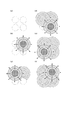
- FIG. 15 shows a state in which a plane on the object surface shows the moment when four pulsating fluids or intermittent fluids fall and collide with the object surface.
- FIG. 15A four circles are drawn with broken lines, and this simply shows the position of the falling center of the falling pulsating fluid or intermittent fluid.
- FIG. 15 (b) shows a liquid film diffusing on the object surface.
- FIG. 15C shows a liquid film diffusing on the object surface.
- FIG. 15D one liquid mass reaches the object surface at the lower right position and collides with it, and as shown in FIG.
- the liquid mass reaches the object surface and collides, and as shown in FIG. 15F, one liquid mass reaches the object surface and collides at the lower left position. In this way, the liquid mass randomly reaches the object surface at various positions.
- FIG. 14B simply shows a case where the pulsating fluid or the intermittent fluid is emitted in synchronization with each other for comparison.
- the foam liquid masses of the pulsating fluid or the intermittent fluid reach the object surface all at once in synchronism with each other and come into contact with the dirt all at once.
- one foam liquid mass hits the dirt so that it collapses without rebounding, and its kinetic energy is given to the dirt, but because it collapses laterally at the same time, adjacent foam liquid mass diffuses laterally at the same time. Therefore, mutual collision is likely to occur, and kinetic energy loss may occur.
- the jet fluid is a water flow and the outside gas is air.
- the jet fluid is composed of another liquid or gas
- the outside gas is composed of another gas.
- pulsating fluid or intermittent fluid generating device of the present invention For example, if incorporated in a foam water generating piece attached to a tap, for example, a pulsating water flow or an intermittent water flow having excellent cleaning effect is generated. be able to. For example, it can also be incorporated into an apparatus in the field of processing technology.
- a semiconductor manufacturing apparatus when incorporated in a semiconductor manufacturing apparatus, it can be applied as a pulsating flow or intermittent flow forming apparatus even when a starting compound is introduced into a reaction chamber using a carrier fluid.
- it if it incorporates in the water jet peening apparatus with respect to the metal structural member surface, it can be incorporated in the apparatus which forms the pulsating flow and intermittent flow for peening. It can also be incorporated into a cleaning device or an unnecessary material removal device. Instead of a conventional scraper, cleaning can be performed using a pulsating flow or intermittent flow medium, and unnecessary materials such as cutting residues and cullet generated in the manufacturing process can be removed. Further, it can be incorporated into a measuring device or a measuring device.
Landscapes
- Health & Medical Sciences (AREA)
- Life Sciences & Earth Sciences (AREA)
- Engineering & Computer Science (AREA)
- Hydrology & Water Resources (AREA)
- Public Health (AREA)
- Water Supply & Treatment (AREA)
- Nozzles (AREA)
- Cleaning By Liquid Or Steam (AREA)
- Bidet-Like Cleaning Device And Other Flush Toilet Accessories (AREA)
- Spray Control Apparatus (AREA)
- Coating Apparatus (AREA)
- Domestic Plumbing Installations (AREA)
- Jet Pumps And Other Pumps (AREA)
Abstract
Le problème de l'invention concerne un dispositif qui peut générer un écoulement pulsatile ou un écoulement intermittent à partir d'un fluide s'écoulant en continu par la pression du fluide s'écoulant en continu sans utilisation d'une partie d'activation électrique. La solution porte sur un dispositif pour générer un fluide pulsatile ou un fluide intermittent, comprenant : un mécanisme d'injection 110 pour injecter un fluide, qui est un liquide ou un gaz ; une cavité d'espace 120 qui est un espace fermé dont l'intérieur est rempli d'air extérieur ; une partie 150 de drainage de fluide disposée dans la partie inférieure ; et un trou de guidage d'air 141 relié à un trajet de ventilation 140. Le point d'injection du mécanisme d'injection 110 se situe à proximité du trou de guidage d'air 141 et le fluide injecté est formé de manière telle qu'une partie du fluide injecté s'écoule vers le bas tout en couvrant la surface d'une paroi latérale qui comprend le trou de guidage d'air 141 de manière à limiter la quantité de ventilation pour l'air extérieur depuis le trou de guidage d'air 141. Un rythme fort-faible pour l'air extérieur insufflé se produit en raison de variations, une chute de pression formée temporairement à l'intérieur de la cavité d'espace 120 par l'écoulement vers le bas du fluide injecté et une récupération temporaire de la pression par de l'air extérieur insufflé depuis le trou de guidage d'air 141 étant répétées ; par conséquent, le fluide provenant du mécanisme d'injection 110 donne lieu à un écoulement pulsatile ou à un écoulement intermittent.
Priority Applications (7)
| Application Number | Priority Date | Filing Date | Title |
|---|---|---|---|
| US15/748,917 US11097287B2 (en) | 2015-07-30 | 2016-06-29 | Device for generating pulsatile flow or intermittent flow |
| AU2016300508A AU2016300508A1 (en) | 2015-07-30 | 2016-06-29 | Device for generating pulsatile flow or intermittent flow |
| CN201680044677.2A CN107921447B (zh) | 2015-07-30 | 2016-06-29 | 脉动流体或断续流体的生成装置 |
| EP16830224.8A EP3330005B1 (fr) | 2015-07-30 | 2016-06-29 | Dispositif pour générer un fluide pulsatile ou un fluide intermittent |
| TW105122349A TWI688430B (zh) | 2015-07-30 | 2016-07-15 | 脈動流體或斷續流體的生成裝置、包含脈動流體或斷續流體的生成裝置的機械裝置及脈動流體或斷續流體的生成方法 |
| SA518391100A SA518391100B1 (ar) | 2015-07-30 | 2018-03-11 | جهاز لتوليد تدفق نابض أو تدفق متقطع |
| AU2019271957A AU2019271957B2 (en) | 2015-07-30 | 2019-11-27 | Device for generating pulsatile flow or intermittent flow |
Applications Claiming Priority (2)
| Application Number | Priority Date | Filing Date | Title |
|---|---|---|---|
| JP2015-150970 | 2015-07-30 | ||
| JP2015150970A JP5961733B1 (ja) | 2015-07-30 | 2015-07-30 | 脈動流体または断続流体の生成装置 |
Publications (1)
| Publication Number | Publication Date |
|---|---|
| WO2017018119A1 true WO2017018119A1 (fr) | 2017-02-02 |
Family
ID=56550485
Family Applications (1)
| Application Number | Title | Priority Date | Filing Date |
|---|---|---|---|
| PCT/JP2016/069300 Ceased WO2017018119A1 (fr) | 2015-07-30 | 2016-06-29 | Dispositif pour générer un fluide pulsatile ou un fluide intermittent |
Country Status (8)
| Country | Link |
|---|---|
| US (1) | US11097287B2 (fr) |
| EP (1) | EP3330005B1 (fr) |
| JP (1) | JP5961733B1 (fr) |
| CN (1) | CN107921447B (fr) |
| AU (2) | AU2016300508A1 (fr) |
| SA (1) | SA518391100B1 (fr) |
| TW (1) | TWI688430B (fr) |
| WO (1) | WO2017018119A1 (fr) |
Families Citing this family (3)
| Publication number | Priority date | Publication date | Assignee | Title |
|---|---|---|---|---|
| US10953416B2 (en) | 2018-02-13 | 2021-03-23 | Yung-Chieh Tan | Liquid saving device |
| JP7623656B2 (ja) | 2021-12-25 | 2025-01-29 | 株式会社Dgtakano | 吐水装置 |
| CN116251785A (zh) * | 2023-03-28 | 2023-06-13 | 至微半导体(上海)有限公司 | 一种防回流的晶圆清洗装置 |
Citations (8)
| Publication number | Priority date | Publication date | Assignee | Title |
|---|---|---|---|---|
| JPS5050162A (fr) * | 1973-09-04 | 1975-05-06 | ||
| JPS59132957A (ja) * | 1983-01-21 | 1984-07-31 | Nichias Corp | ペ−スト状組成物の噴射塗装方法およびその装置 |
| JPS63229162A (ja) * | 1987-03-19 | 1988-09-26 | Koichi Kawamura | 噴水ノズル装置 |
| JPH10296195A (ja) * | 1997-04-22 | 1998-11-10 | Maruyama Mfg Co Ltd | 洗浄方法及び装置 |
| JP2001123506A (ja) * | 1999-10-29 | 2001-05-08 | Nippon Control Kogyo Co Ltd | 水流脈動発生装置 |
| WO2010109680A1 (fr) * | 2009-03-26 | 2010-09-30 | Takano Masaaki | Bouchon de génération d'eau moussante |
| JP2012047111A (ja) * | 2010-08-27 | 2012-03-08 | Seiko Epson Corp | 流体噴射装置 |
| WO2012033126A1 (fr) * | 2010-09-11 | 2012-03-15 | Takano Masaaki | Tournant produisant de l'eau à effet moussant |
Family Cites Families (12)
| Publication number | Priority date | Publication date | Assignee | Title |
|---|---|---|---|---|
| US3801019A (en) | 1972-06-21 | 1974-04-02 | Teledyne Ind | Spray nozzle |
| US4484710A (en) * | 1983-03-11 | 1984-11-27 | The United States Of America As Represented By The Secretary Of The Army | Fire suppressant nozzle |
| US4869103A (en) * | 1988-06-03 | 1989-09-26 | Jerman James K | Water flow measuring and dispersing device |
| JPH0995985A (ja) | 1995-09-29 | 1997-04-08 | Just Ace:Kk | 節水コマ |
| US5826799A (en) * | 1996-12-03 | 1998-10-27 | Hsieh; Paul | Sprinkling head structure |
| JP2000104300A (ja) | 1998-09-30 | 2000-04-11 | Seiko Sangyo:Kk | 節水コマ |
| DE10008438A1 (de) * | 2000-02-23 | 2001-08-30 | Grohe Armaturen Friedrich | Brausevorrichtung |
| CN102154628B (zh) * | 2004-08-02 | 2014-05-07 | 维高仪器股份有限公司 | 用于化学气相沉积反应器的多气体分配喷射器 |
| US7611070B2 (en) * | 2006-02-28 | 2009-11-03 | Paoluccio John J | Aspirating scented oxygen enriched faucet and shower head |
| JP5854186B2 (ja) * | 2011-03-14 | 2016-02-09 | Toto株式会社 | シャワー装置 |
| JP5862093B2 (ja) * | 2011-07-28 | 2016-02-16 | セイコーエプソン株式会社 | 液体収容容器、液体噴射システム、及び、液体供給システム |
| US9272437B2 (en) * | 2012-10-31 | 2016-03-01 | Flow International Corporation | Fluid distribution components of high-pressure fluid jet systems |
-
2015
- 2015-07-30 JP JP2015150970A patent/JP5961733B1/ja active Active
-
2016
- 2016-06-29 AU AU2016300508A patent/AU2016300508A1/en not_active Abandoned
- 2016-06-29 US US15/748,917 patent/US11097287B2/en active Active
- 2016-06-29 WO PCT/JP2016/069300 patent/WO2017018119A1/fr not_active Ceased
- 2016-06-29 CN CN201680044677.2A patent/CN107921447B/zh active Active
- 2016-06-29 EP EP16830224.8A patent/EP3330005B1/fr active Active
- 2016-07-15 TW TW105122349A patent/TWI688430B/zh active
-
2018
- 2018-03-11 SA SA518391100A patent/SA518391100B1/ar unknown
-
2019
- 2019-11-27 AU AU2019271957A patent/AU2019271957B2/en active Active
Patent Citations (8)
| Publication number | Priority date | Publication date | Assignee | Title |
|---|---|---|---|---|
| JPS5050162A (fr) * | 1973-09-04 | 1975-05-06 | ||
| JPS59132957A (ja) * | 1983-01-21 | 1984-07-31 | Nichias Corp | ペ−スト状組成物の噴射塗装方法およびその装置 |
| JPS63229162A (ja) * | 1987-03-19 | 1988-09-26 | Koichi Kawamura | 噴水ノズル装置 |
| JPH10296195A (ja) * | 1997-04-22 | 1998-11-10 | Maruyama Mfg Co Ltd | 洗浄方法及び装置 |
| JP2001123506A (ja) * | 1999-10-29 | 2001-05-08 | Nippon Control Kogyo Co Ltd | 水流脈動発生装置 |
| WO2010109680A1 (fr) * | 2009-03-26 | 2010-09-30 | Takano Masaaki | Bouchon de génération d'eau moussante |
| JP2012047111A (ja) * | 2010-08-27 | 2012-03-08 | Seiko Epson Corp | 流体噴射装置 |
| WO2012033126A1 (fr) * | 2010-09-11 | 2012-03-15 | Takano Masaaki | Tournant produisant de l'eau à effet moussant |
Also Published As
| Publication number | Publication date |
|---|---|
| EP3330005A4 (fr) | 2018-07-25 |
| CN107921447B (zh) | 2020-04-07 |
| JP2017031611A (ja) | 2017-02-09 |
| EP3330005B1 (fr) | 2020-05-13 |
| AU2019271957A1 (en) | 2019-12-19 |
| CN107921447A (zh) | 2018-04-17 |
| EP3330005A1 (fr) | 2018-06-06 |
| SA518391100B1 (ar) | 2021-10-31 |
| JP5961733B1 (ja) | 2016-08-02 |
| TWI688430B (zh) | 2020-03-21 |
| US11097287B2 (en) | 2021-08-24 |
| AU2016300508A1 (en) | 2018-03-08 |
| US20190009283A1 (en) | 2019-01-10 |
| AU2019271957B2 (en) | 2021-05-27 |
| TW201703869A (zh) | 2017-02-01 |
Similar Documents
| Publication | Publication Date | Title |
|---|---|---|
| CN102574169B (zh) | 一种用于清洁表面的装置及其方法 | |
| KR101697840B1 (ko) | 샤워기 변기를 위한 샤워기 암 | |
| CN108024669B (zh) | 吐水装置 | |
| JP6699071B2 (ja) | 吐水装置 | |
| JP5961733B1 (ja) | 脈動流体または断続流体の生成装置 | |
| TWI617274B (zh) | 吐水裝置 | |
| JPS62225234A (ja) | アスピレ−シヨン泡発生装置 | |
| JP2018167164A (ja) | 吐水装置 | |
| US8449688B2 (en) | High-pressure liquid atomisation nozzle for a machine for cleaning optical lenses or other substrates | |
| JP2008302054A (ja) | 微細気泡発生装置 | |
| JP5588582B2 (ja) | 洗浄装置 | |
| JP2017109152A (ja) | 吐水装置 | |
| JP2008136931A (ja) | 液吐出装置 | |
| JP2017064097A (ja) | 吐水装置 | |
| JP2018166685A (ja) | 吐水装置 | |
| JP2009291699A (ja) | 消火用ノズル装置 | |
| JP2007160175A (ja) | 洗浄装置 | |
| JP2017064098A (ja) | 吐水装置 | |
| JP6735026B2 (ja) | シャワーヘッド | |
| CN102405321B (zh) | 泡沫水生成水塞 | |
| JP2017108831A (ja) | 吐水装置 | |
| NL2025098B1 (en) | Spraying system for delivering cleaning foam | |
| JP5762422B2 (ja) | 節水コマ | |
| JP7778973B1 (ja) | ファインバブル水生成器及びファインバブル水生成器付き洗濯機用給水ホース | |
| KR102816956B1 (ko) | 초음파 나노 버블 비데 |
Legal Events
| Date | Code | Title | Description |
|---|---|---|---|
| 121 | Ep: the epo has been informed by wipo that ep was designated in this application |
Ref document number: 16830224 Country of ref document: EP Kind code of ref document: A1 |
|
| NENP | Non-entry into the national phase |
Ref country code: DE |
|
| ENP | Entry into the national phase |
Ref document number: 2016300508 Country of ref document: AU Date of ref document: 20160629 Kind code of ref document: A |