WO2010119829A1 - Dispositif de traitement d'informations, procédé de traitement d'informations et programme - Google Patents
Dispositif de traitement d'informations, procédé de traitement d'informations et programme Download PDFInfo
- Publication number
- WO2010119829A1 WO2010119829A1 PCT/JP2010/056505 JP2010056505W WO2010119829A1 WO 2010119829 A1 WO2010119829 A1 WO 2010119829A1 JP 2010056505 W JP2010056505 W JP 2010056505W WO 2010119829 A1 WO2010119829 A1 WO 2010119829A1
- Authority
- WO
- WIPO (PCT)
- Prior art keywords
- information
- dimensional object
- image
- change instruction
- mode
- Prior art date
- Legal status (The legal status is an assumption and is not a legal conclusion. Google has not performed a legal analysis and makes no representation as to the accuracy of the status listed.)
- Ceased
Links
Images








Classifications
-
- G—PHYSICS
- G06—COMPUTING OR CALCULATING; COUNTING
- G06F—ELECTRIC DIGITAL DATA PROCESSING
- G06F3/00—Input arrangements for transferring data to be processed into a form capable of being handled by the computer; Output arrangements for transferring data from processing unit to output unit, e.g. interface arrangements
- G06F3/01—Input arrangements or combined input and output arrangements for interaction between user and computer
- G06F3/048—Interaction techniques based on graphical user interfaces [GUI]
- G06F3/0481—Interaction techniques based on graphical user interfaces [GUI] based on specific properties of the displayed interaction object or a metaphor-based environment, e.g. interaction with desktop elements like windows or icons, or assisted by a cursor's changing behaviour or appearance
-
- G—PHYSICS
- G06—COMPUTING OR CALCULATING; COUNTING
- G06F—ELECTRIC DIGITAL DATA PROCESSING
- G06F3/00—Input arrangements for transferring data to be processed into a form capable of being handled by the computer; Output arrangements for transferring data from processing unit to output unit, e.g. interface arrangements
- G06F3/01—Input arrangements or combined input and output arrangements for interaction between user and computer
- G06F3/048—Interaction techniques based on graphical user interfaces [GUI]
- G06F3/0487—Interaction techniques based on graphical user interfaces [GUI] using specific features provided by the input device, e.g. functions controlled by the rotation of a mouse with dual sensing arrangements, or of the nature of the input device, e.g. tap gestures based on pressure sensed by a digitiser
- G06F3/0488—Interaction techniques based on graphical user interfaces [GUI] using specific features provided by the input device, e.g. functions controlled by the rotation of a mouse with dual sensing arrangements, or of the nature of the input device, e.g. tap gestures based on pressure sensed by a digitiser using a touch-screen or digitiser, e.g. input of commands through traced gestures
-
- G—PHYSICS
- G06—COMPUTING OR CALCULATING; COUNTING
- G06F—ELECTRIC DIGITAL DATA PROCESSING
- G06F2203/00—Indexing scheme relating to G06F3/00 - G06F3/048
- G06F2203/048—Indexing scheme relating to G06F3/048
- G06F2203/04802—3D-info-object: information is displayed on the internal or external surface of a three dimensional manipulable object, e.g. on the faces of a cube that can be rotated by the user
Definitions
- the present invention relates to an information processing apparatus that displays a three-dimensional image or the like.
- a menu item is assigned to each area of a three-dimensional figure, a display step for displaying the three-dimensional figure, a movement step for moving the three-dimensional figure according to an instruction command to be input, and an assignment to the three-dimensional figure
- a three-dimensional menu selection method comprising: a selection step for selecting a required menu from a given menu item; and a selection processing execution step for executing processing corresponding to the selected menu.
- JP-A-7-114451 (first page, FIG. 1 etc.)
- the back surface of the three-dimensional object overlaps with the front portion of the three-dimensional object and is hidden behind the front surface. For this reason, the subject that the back of a solid object cannot be displayed occurred. For this reason, in order to view the image on the back of the three-dimensional object, it is necessary to rotate the three-dimensional object, which takes time and effort and is not convenient.
- each surface of the 3D object is displayed transparently, it is possible to visually recognize what information is arranged on the back of the 3D object without operating the 3D object. Is possible.
- the rear image is combined with the front image and displayed, there is a problem that it becomes difficult to grasp the front information. For example, when there is no need to see the back image, the back image simply becomes an image that hinders the visibility of the front image.
- An information processing apparatus is arranged on a shape information storage unit that can store shape information that is information for designating the shape of a three-dimensional object that is a three-dimensional object, and 1 arranged on one or more surfaces constituting the three-dimensional object.
- An arrangement information storage unit that can store arrangement information that is the above information, and a composition mode change instruction that is an instruction to change the composition mode for at least the front and back of the surfaces constituting the solid object.
- An information processing apparatus comprising: an image information configuration unit that configures image information synthesized according to a synthesis mode in which a composition mode change instruction instructs a change; and an output unit that outputs image information configured by the image information configuration unit is there.
- the 3D object can be displayed appropriately by switching the synthesis mode of the surfaces constituting the 3D object.
- the arrangement information arranged on the back surface of the three-dimensional object can be made visible or invisible from the front side. Visibility can be improved.
- the composition mode change instruction is an instruction to change transparency
- the image information configuration unit includes: This is an information processing apparatus that configures image information in which the transparency of at least a surface disposed in front of at least the front and back overlapping surfaces is changed.
- the 3D object can be appropriately displayed by switching the synthesis mode for the transparency of the surfaces constituting the 3D object. Accordingly, for example, by switching the composition mode for transparency, it is possible to appropriately transmit the front surface of the three-dimensional object so that the arrangement information arranged on the back surface of the three-dimensional object can be viewed from the front side. Or can be switched from being visually recognized, and the visibility of the three-dimensional object can be improved according to the situation.
- the composition mode change instruction receiving unit includes position specifying information receiving means for receiving position specifying information that is information for specifying a position of an image indicated by the image information.
- An information processing apparatus comprising: a synthesis mode acquisition unit configured to acquire a synthesis mode change instruction for the three-dimensional object according to a positional relationship between the position designated by the position designation information and the position of the three-dimensional object in the image information. It is.
- the information processing apparatus is the information processing apparatus, wherein the synthesis mode acquisition unit acquires a synthesis mode change instruction that designates one of two or more different synthesis modes according to the positional relationship. Device.
- the composition mode can be switched and displayed.
- the synthesis mode acquisition unit determines whether the position specified by the position specifying information is a position in a predetermined area on the three-dimensional object. It is an information processing apparatus that detects and acquires a compositing mode change instruction for the solid object according to the detection result.
- the information processing apparatus or the like it is possible to switch the composition mode of the surfaces constituting the three-dimensional object and display the three-dimensional object appropriately.
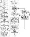
- the block diagram of the information processing apparatus concerning embodiment of this invention Flow chart for explaining the operation of the information processing apparatus
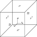
- movement of the information processing apparatus The figure for demonstrating the name of each surface of a solid object for demonstrating operation
- movement of the information processing apparatus The figure which shows the acquisition condition information management table for demonstrating operation
- movement of the information processing apparatus The figure which shows the area
- the figure which shows the example of a display by the information processing apparatus The figure which shows the operation condition for demonstrating operation
- region designation information shows in order to demonstrate operation
- the figure which shows the output example of the information processing apparatus The figure which shows the operation condition for demonstrating operation
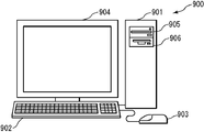
- the figure which shows the output example of the information processing apparatus Schematic diagram showing an example of the external appearance of the computer system
- FIG. 1 is a block diagram of an information processing apparatus 1 in the present embodiment.
- the information processing apparatus 1 includes a shape information storage unit 101, an arrangement information storage unit 102, a three-dimensional object position information storage unit 103, a synthesis mode change instruction acquisition unit 104, an image information configuration unit 105, and an output unit 106.
- the composition mode change instruction acquisition unit 104 includes position designation information reception means 1041 and composition mode acquisition means 1042.
- the information processing apparatus 1 includes, for example, a computer, a mobile phone, a PDA (personal digital assistant), a high-function mobile phone that combines a mobile phone and an information terminal, a portable digital music player, a television, and the like.
- Information devices such as audio-visual devices having a display device. The same applies to other embodiments.
- the shape information storage unit 101 can store shape information that is information specifying the shape of a three-dimensional object that is a three-dimensional object.
- the shape information is information that defines the shape or the like of an object arranged in the virtual three-dimensional space.
- the shape information is so-called modeling information of a three-dimensional object, for example.
- the three-dimensional object described here includes, for example, what is called a 3D object, a 3D model, or a three-dimensional model.
- the shape information is information on the coordinates of the vertices of the three-dimensional object, information on parameters of equations that express boundary lines, surfaces, and the like.
- a solid object usually has information that defines a surface or information that can define a surface, and is composed of one or more surfaces.
- the three-dimensional object can be classified into polygon modeling, modeling using a free-form surface, and the like, for example, depending on the method of constructing the surface.
- the shape information may include information on setting items such as the color of the 3D object, transparency, reflection, refractive index, and bump when the 3D object is output.
- the shape information storage unit 101 can store shape information of one or more solid objects.
- the shape of the three-dimensional object may be any shape such as a sphere, a cylinder, a polyhedron such as a hexahedron or an octahedron, a cube, a cone, or a pyramid.
- a unit such as a size of the shape information may be an absolute unit or a relative unit.
- the shape information storage unit 101 is preferably a non-volatile recording medium, but can also be realized by a volatile recording medium.
- the placement information storage unit 102 can store placement information that is one or more pieces of information that can be placed on the surfaces constituting the three-dimensional object.
- the placement information may be any information such as image information such as a still image and a moving image, text information, and the like as long as it is information that can be output and displayed, for example, by placing it on the surface constituting the solid object.
- the arrangement described here may be considered as mapping of image information or the like on the surface of a so-called solid object.
- the arrangement information may be considered as information to be mapped, for example, texture information.
- the data structure of the placement information is not limited.
- the placement information may be tagged information.
- the placement information may be information managed in association with attributes or the like by using a table or a database. Further, the placement information may be grouped in advance.
- the arrangement information may be associated with the surface of the three-dimensional object on which the arrangement information is arranged.
- management information or the like that manages a set of placement information or its identification information and a surface of the solid object associated with the placement information or its identification information as a plurality of items of one record May be.
- This management information may be stored in a storage unit (not shown), for example.
- the shape information storage unit 101 and the placement information storage unit 102 are configured as a single storage unit, and the information indicating the surface of the three-dimensional object indicated by the shape information corresponds to the placement information placed on the surface. It may be attached and stored.
- the shape information storage unit 101 or the like is associated with the surface of the solid object indicated by the shape information in association with acquisition condition information or the like indicating information for acquiring the placement information arranged on the surface. May be stored.
- the acquisition condition information is, for example, information indicating a search condition such as a search expression for searching for placement information arranged on a surface. In this case, by performing a search using information such as a search expression associated with each surface, it is possible to acquire the placement information placed on the surface.
- the information acquisition condition information may be any information as long as it is information that can eventually designate one or more pieces of placement information arranged on the surface of one or more solid objects.
- the acquisition condition information may be information specifying the item.
- the placement information has an attribute, it may be information specifying the attribute.
- the placement information is tagged, it may be information specifying a tag name.
- index information is added to the placement information, information for designating the index may be used.
- it may be information designating the location, file name, directory, etc. of the placement information.
- it may be a search expression or an arithmetic expression for searching the arrangement information.
- the search formula does not necessarily have to be shown in the form of a formula, and may be a keyword that can be used for the search.
- the acquisition condition information indicated by this search expression is a combination of “select”, “from”, “where”, and the like. Note that “select” is an item of information for arrangement to be acquired, “from” is information for specifying a plurality of pieces of information for arrangement to be searched, and “where” is information indicating conditions for search (SQL specification) See).
- the acquisition condition information indicated by the arithmetic expression is, for example, an arithmetic expression performed on one or more pieces of arrangement information, for example, information specifying two pieces of arrangement information represented by numerical values, and these Are expressed by an arithmetic expression for calculating the average of the above, an arithmetic expression for adding / subtracting a predetermined time to / from a current time, and the like.
- the acquisition condition information may be individually specified for all solid objects that can be output, or may be specified for all solid objects. Further, it may be specified in common for some solid objects. When an attribute or the like is set for a solid object, a common acquisition condition may be specified for a solid object that matches the attribute.
- the acquisition condition information may be specified in advance for each surface of the three-dimensional object, or may be specified randomly for each surface.
- the placement information storage unit 102 is preferably a non-volatile recording medium, but can also be realized by a volatile recording medium.
- three-dimensional object position information which is information for designating the position of the three-dimensional object
- the position described here is, for example, a position in the virtual three-dimensional space.
- the three-dimensional object position information may be position information on a two-dimensional plane.
- the three-dimensional object position information may include, for example, information indicating the direction in which the three-dimensional object is arranged, that is, the direction of the object, the size of the three-dimensional object, and the like in addition to the position of the three-dimensional object.
- the position of the three-dimensional object may be considered as, for example, the position of one or more parts in the three-dimensional object in the virtual three-dimensional space.
- the position of the three-dimensional object may be a position of one or more vertices, sides, or faces where the sides constituting the three-dimensional object are gathered, or may be a position such as the center or the center of gravity of the three-dimensional object.
- the three-dimensional object position information only needs to be information that can eventually specify the position of the three-dimensional object.
- the three-dimensional object position information is information that designates coordinates of a position where the three-dimensional object is arranged, for example.
- the position of the three-dimensional object is represented by coordinates, for example.
- the coordinates for designating the position of the three-dimensional object may be absolute coordinates set in a virtual three-dimensional space or the like, or may be relative coordinates set for another three-dimensional object or the like. good.
- the coordinates for designating the position of the three-dimensional object may be the coordinates of the vertices where the sides constituting the three-dimensional object gather, or the coordinates of the positions of the center and the center of gravity of the three-dimensional object.
- three-dimensional object position information and three-dimensional object shape information are provided for each of one or more three-dimensional objects, but the three-dimensional object position information may be included in the shape information.
- the position of the three-dimensional object can be specified using the shape information as the three-dimensional object position information.
- the shape information storage unit 101 and the three-dimensional object position information storage unit 103 may be configured by a single storage unit.
- the image information configuration unit 105 described later reads the solid object position information, and configures image information in which the solid object is positioned at a position in the virtual three-dimensional space indicated by the solid object position information.
- the three-dimensional object position information storage unit 103 is preferably a non-volatile recording medium, but can also be realized by a volatile recording medium.
- the composition mode change instruction acquisition unit 104 acquires a composition mode change instruction that is an instruction to change the composition mode for at least the front and back surfaces of the surfaces constituting the solid object.
- the synthesis mode change instruction may be considered as information indicating an instruction to change the synthesis mode with respect to the synthesis mode designated by default or the current synthesis mode.
- the composition mode change instruction may be an instruction to change the composition mode after the change to a composition mode different from the composition mode before the change, and includes information for explicitly specifying the composition mode after the change. It may or may not be included.
- the combination mode change instruction acquired by the combination mode change instruction acquisition unit 104 in the case of including information that explicitly specifies the changed combination mode is, for example, an instruction to change the combination mode to a mode that transmits at 90% transparency
- the synthesis mode change instruction acquired by the synthesis mode change instruction acquisition unit 104 when the information that explicitly specifies the changed synthesis mode is not included is, for example, an instruction to change to a synthesis mode different from the current synthesis mode, etc.
- Information indicating a synthesis mode different from that before the change may be considered as a synthesis mode change instruction.
- the 3D object compositing mode is, for example, a compositing method that indicates how to synthesize a front and back overlapping surface.
- this is a surface composition method that indicates how an image arranged on the front side is to be synthesized with an image arranged on the back side of the image.
- a pixel obtained by performing a predetermined calculation designated by the synthesis mode using values of pixels of images arranged on the overlapping surfaces is a synthesized pixel.
- the synthesis mode is also called, for example, a drawing mode.
- the composition mode is, for example, a mode in which an image is transmitted with a predetermined transparency and combined. In this case, the synthesis mode change instruction may be considered as an instruction to change the transparency.
- This combination mode change instruction may or may not have information for designating the transparency. If not, it can be considered as information specifying a synthesis mode for transmitting an image with a preset transparency.
- the transparency may be a value indicating transparency such as 0 to 100%, or may be qualitative data associated with a value indicating transparency such as “transparency” or “semi-transparency”. good. Note that when the transparency is 0%, that is, when the transmission is not performed, or when the transparency is 100%, that is, when the target image is not displayed, it may be considered as a transmission mode or a different mode. good.
- modes such as multiplication, overlay, and dither synthesis are known.
- composition modes In different composition modes, arithmetic expressions, parameters, and the like at the time of composition are different. A combination of the transmission mode and another synthesis mode may be considered as one of the synthesis modes. Since the synthesis mode and the processing for synthesizing images according to the synthesis mode are known techniques in 3D software, image processing software, and the like, description thereof is omitted here. Note that, in the present application, the composition mode instructed by the composition mode change instruction is a composition mode in which all or part of the back image can be transmitted so that the user can recognize the image from the front. Is preferred.
- the synthesis mode of the three-dimensional object is a method of indicating how to display an image placed on the front side with respect to an image placed on the back side of the image, or placed on the front side. Since it can be considered to be a display method for displaying an image and an image arranged on the back of the image in a superimposed manner, it may be considered as a display mode of a three-dimensional object.
- the front surface described here is specifically located forward, that is, on the viewpoint side when the virtual three-dimensional space of the surfaces constituting the three-dimensional object is viewed from a virtual viewpoint specified in advance. It is a surface to do.
- the viewpoint here is a viewpoint at the time of rendering or the like.
- the back surface is a surface located behind the front surface. Note that the side close to the surface of the screen on which the image of the three-dimensional object is displayed may be considered as the front surface.
- only the surface at least partially overlapping the front surface may be considered as the back surface.
- only the overlapping area may be considered as the back surface.
- the overlapped front portion may be considered the front surface and the overlapped rear portion may be considered the back surface.
- the compositing mode change instruction may be an instruction to change the compositing mode of overlapping surfaces in different three-dimensional objects. Further, the compositing mode change instruction may be considered to include an instruction to change the compositing mode with respect to the background image of the area where the solid object is arranged on each surface constituting the solid object. For example, when the first surface and the second surface are arranged in the virtual three-dimensional space, an instruction to change the composition mode of the three-dimensional object to the composition mode that transmits the image with 50% transparency is composed. When the mode change instruction is received, the transparency of the first surface and the second surface may be set to 50%, respectively, so that the background can be seen through. Alternatively, only the transmittance of the surface disposed on the front surface of the first surface and the second surface is changed to 50%, and the surface disposed on the back surface cannot be seen through. You may do it.
- the compositing mode change instruction may or may not include information for designating a three-dimensional object for which the compositing mode is to be changed and information for designating a surface of the three-dimensional object for which the compositing mode is to be changed.
- the composition mode of one or more pre-designated three-dimensional objects or a predesignated surface is changed when the image information composing unit 105 described later composes an image.
- the compositing mode change instruction for a solid object including another solid object inside, that is, a solid object having a nested structure may be considered as information for changing the compositing mode for the outer solid object. It may also be considered as information for changing the composition mode for both of the solid objects located inside.
- the synthesis mode change instruction acquisition unit 104 acquires, for example, a synthesis mode change instruction for changing the synthesis mode between two or more different synthesis modes.
- the different synthesis modes may mean that the synthesis modes themselves are different, or that parameters or the like are different in one synthesis mode.
- the multiplication mode and the overlay mode may be considered as different synthesis modes, or those with different parameter values used for synthesis in one synthesis mode may be considered as different synthesis modes. good.
- a mode in which an image is transmitted with different transparency such as a set of a mode in which an image is transmitted with 0% transparency and a mode in which an image is transmitted with 50% transparency, may be considered as different synthesis modes. good.
- the transparency or the like may be set to a value that makes it easy to see the synthesized image.
- the composition mode change instruction acquisition unit 104 uses a mouse, a keyboard, an input device such as a touch pad, or the like to operate a composite mode input by operating an input interface such as a button for switching a composition mode or an input menu. Accepting a mode change instruction may be considered as acquisition. Further, the synthesis mode change instruction acquisition unit 104 may acquire a synthesis mode change instruction corresponding to the relationship between the position where the solid object is displayed and the position on the display image specified by the user.
- “Reception” refers to reception of information input from an input device such as a keyboard, mouse, touch panel, reception of information transmitted via a wired or wireless communication line, an optical disk, a magnetic disk, a recording medium such as a semiconductor memory, etc. This is a concept including reception of information read out from.
- the input means may be anything such as a numeric keypad, keyboard, mouse or menu screen.
- the synthesis mode change instruction acquisition unit 104 can be realized by a device driver for input means such as a numeric keypad or a keyboard, control software for a menu screen, or the like.
- the combination mode change instruction acquisition unit 104 includes the position designation information reception unit 1041 and the combination mode acquisition unit 1042, and uses these to acquire a combination mode change instruction.
- the combination mode change instruction acquired by the combination mode acquisition unit 1042 may be considered as the combination mode change instruction acquired by the combination mode change instruction acquisition unit 104.
- the position designation information accepting unit 1041 accepts position designation information that is information for designating a position on the image indicated by the image information.
- the position designation information receiving unit 1041 designates the position on the image indicated by the image information output by the output unit 106, which will be described later, designated by the user or the like using an input unit such as a mouse, a keyboard, or a touch panel.
- Accept location specification information The information that designates the position on the image is information that designates a position where a pointer, a cursor, or the like exists, for example.
- it is information for designating a position touched by a finger on a touch panel or the like.
- the information specifying the position is, for example, coordinate information corresponding to the display screen or the displayed image information.
- the coordinate information received by the position designation information receiving unit 1041 may be coordinate information in a virtual three-dimensional space calculated from information on the position of a pointer or cursor.
- the position designation information accepting unit 1041 may accept position designation information about a position where a pointer, cursor or finger exists, for example, at a predetermined timing such as a predetermined time interval, or there is a pointer or cursor.
- the position designation information may be received when a predetermined operation such as a click on a mouse button or the like, a pressing of a predetermined key such as an Enter key, or a tap on a touch panel or the like with a finger is performed at the position to be performed. .
- the position specifying information input means may be anything such as a numeric keypad, a keyboard, a mouse, or a menu screen.
- the position designation information receiving unit 1041 can be realized by a device driver of an input unit such as a numeric keypad, a keyboard, or a touch panel, or control software for a menu screen.
- the compositing mode acquisition unit 1042 acquires a compositing mode change instruction for the three-dimensional object according to the positional relationship between the position specified by the position specifying information and the position of the three-dimensional object in the image information.
- the acquisition of the synthesis mode change instruction described here is, for example, reading of a synthesis mode change instruction, generation of a synthesis mode change instruction, or the like.
- the synthesis mode change instruction acquired here may be, for example, an instruction including information for designating the solid object used for determining the positional relationship when acquiring the synthesis mode change instruction as the synthesis mode change target.
- the combination mode acquisition unit 1042 acquires a combination mode change instruction that specifies one of two or more different combination modes according to the positional relationship.
- the acquisition of the compositing mode change instruction according to the positional relationship is, for example, the acquisition of the compositing mode change instruction according to the distance relationship between the position specified by the position specifying information and the position of the three-dimensional object. Further, it is also possible to acquire the compositing mode change instruction according to the detection result of whether or not the position specified by the position specifying information is a position in a predetermined area on the solid object.
- the composition mode acquisition unit 1042 acquires the position designated by the position designation information and the position information of one solid object in the image information, and the position designated by the position designation information and the image information from the position information. The distance from the position of one solid object at is calculated. Then, in accordance with the distance between the position designated by the position designation information and the position of the solid object in the image information, a synthesis mode change instruction for the solid object is acquired.
- Exceeding the threshold described here may mean that the distance is less than the threshold or more than the threshold, or may be that the distance is more than the threshold or less than the threshold. good.
- the synthesis mode acquisition unit 1042 switches to one of the two synthesis modes designated in advance and one of the synthesis modes other than the current synthesis mode.
- the composition mode change instruction for changing the composition mode of the three-dimensional object may be acquired.
- At least a part of values that can be taken by the distance between the position designated by the position designation information and the position of the three-dimensional object in the image information is preliminarily used in two or more stages.
- the distance between the position designated by the position designation information and the position of the one three-dimensional object in the image information so that information indicating different synthesis modes is associated with each stage is the above-mentioned 2.
- Information specifying the synthesis mode may be acquired as a synthesis mode change instruction for the three-dimensional object. This determination may be made only when the stage in which the distance is included changes.
- the composition mode of the three-dimensional object can be changed step by step as the position designated by the position designation information approaches the three-dimensional object.
- the synthesis mode change instruction is information specifying the transparency, that is, information specifying the synthesis mode for changing the transparency to the specified transparency, the higher the transparency is associated with the shorter distance.
- the transparency of the three-dimensional object can be increased stepwise.
- a range of one or more distance values bounded by one or more threshold values specified in advance and information indicating one or more synthesis modes are associated with each other in advance in a storage unit (not shown).
- a range of values with the threshold value as a boundary
- a combination mode conversion instruction for specifying a combination mode associated with a range of values including the distance between the position specified by the position specifying information and the position of the three-dimensional object in the image information may be acquired.
- the information indicating the synthesis mode associated with the range of distance values in this case may be information for specifying the synthesis mode, or specify one parameter of the synthesis mode, such as a transparency value. It may be information to do.
- the value of the distance between the position specified by the position specification information and the position of the solid object in the image information is assigned to a variable, it is possible to specify in advance a value such as a transparency value that can be calculated as a composite mode parameter.
- a predetermined function or the like is prepared in advance in a storage unit (not shown), and the value of the distance between the position designated by the position designation information and the position of the three-dimensional object in the image information is substituted into this function, thereby synthesizing the function.
- a mode parameter may be calculated, and a synthesis mode change instruction for changing the current synthesis mode to a synthesis mode having the calculated parameter may be acquired. In this way, for example, when the above function is a function whose value changes continuously according to the distance, as the position specified by the position specification information approaches the solid object, the synthesis mode of the solid object is continuously set. Can be changed.
- the distance between the position designated by the position designation information and the position of one solid object in the image information is, for example, the position designated by the position designation information and the distance between the one solid object displayed in the image indicated by the image information. It may be a distance from a position designated in advance such as the center or the center of gravity in the image, or may be a distance from a position closest to the position designated by the position designation information in the image of one solid object. .
- Information on the position of the three-dimensional object in the image indicated by the image information for example, information on the coordinates, can be obtained from information on the position of the pixel constituting the image of the three-dimensional object on the image or on the monitor.
- Information such as the coordinates of the pixels constituting the image of the three-dimensional object in the image information can be obtained from information calculated when rendering is performed using shape information or the like, for example.
- information such as the coordinates of the position where the image of this solid object is arranged is displayed. You may get it.
- a compositing mode change instruction may be acquired for each.
- the composition mode acquisition unit 1042 detects whether or not the position specified by the position specification information received by the position specification information reception unit 1041 is a position within a predetermined area on the three-dimensional object, and In response to the detection result, a synthesis mode change instruction for the solid object is acquired.
- Whether or not the position designated by the position designation information is a position within a predetermined area on the solid object is defined by, for example, the coordinates indicated by the position designation information being the coordinates indicating the contour, the coordinates of all the pixels, or the like.
- the combination mode acquisition unit 1042 specifies the combination mode of the three-dimensional object in advance as a default or the like.
- a combination mode change instruction for changing to a combination mode different from the combination mode may be acquired.
- the composition mode may not be changed from a pre-designated composition mode such as default, or the composition mode is already changed from the composition mode such as default.
- the synthesis mode is set to the synthesis mode designated in advance by default or the like. You may acquire the synthetic
- the composition mode acquisition unit 1042 determines that the position specified by the position specification information is a position in a predetermined area on the solid object, and determines that the position is not in the predetermined area. Thus, a synthesis mode change instruction that can designate a different synthesis mode for the three-dimensional object may be acquired.
- the composition mode acquisition unit 1042 uses the detection result of whether or not the position designated by the position designation information is a position in a predetermined area on the solid object, and the position designated by the position designation information is It may be detected that the object enters the area from outside the predetermined area on the object, or that the object moves out of the predetermined area. Then, when these situations are detected, a synthesis mode change instruction for changing the synthesis mode from the immediately preceding synthesis mode may be acquired. When these situations are detected, a synthesis mode change instruction for changing the synthesis mode to the synthesis mode associated with each situation may be acquired.
- the predetermined area may be an entire area on the image of one or more stereoscopic objects in the image indicated by the image information output by the output unit 106, or a partial area on the image of the stereoscopic object. It may be.
- the partial region on the image of the three-dimensional object is, for example, a region on one or more surfaces specified in advance of the three-dimensional object. Alternatively, it may be a region within a predetermined radius centered on the center and the center of gravity of the image of the three-dimensional object, or may be a region obtained by expanding or reducing the contour of the three-dimensional object by a predetermined width.
- a part of the region on the image of the three-dimensional object is, for example, a region on one or more surfaces specified in advance of the three-dimensional object
- information specifying which surface is set as the predetermined region may be stored in a storage unit such as the shape information storage unit 101 in association with information indicating a surface or the like in the shape information.
- information indicating the area of the 3D object in the image information corresponding to the surface of the 3D object in the shape information such as coordinate information of the outline of this area, when rendering the 3D object to a two-dimensional image, etc.
- the coordinates of the contour of the region where the surface is displayed by calculation may be calculated.
- obtaining a compositing mode change instruction for the three-dimensional object is a position designated by the position designation information; It may be considered that the compositing mode change instruction is acquired according to the direction of the solid object in the image information. For example, from the coordinate information specified by the position specification information and the coordinate information of the three-dimensional object in the image information, the position specified by the position specification information is below or above the position of the three-dimensional object. Or left, etc., and a synthesis mode change instruction may be acquired according to the determination result.
- a synthesis mode change instruction is obtained, and if it is not below, it is not necessary to obtain a synthesis mode change instruction. Further, the angle of the position of the other coordinate when one of the two coordinates is used as a reference may be calculated, and the combination mode change instruction may be acquired according to the angle.
- the synthesis mode acquisition unit 1042 can be usually realized by an MPU, a memory, or the like.
- the processing procedure of the synthesis mode acquisition unit 1042 is usually realized by software, and the software is recorded on a recording medium such as a ROM. However, it may be realized by hardware (dedicated circuit).
- the image information configuration unit 105 reads the shape information of the three-dimensional object and the arrangement information arranged on one or more surfaces of the three-dimensional object. Then, the composition mode change instruction instructs to change at least the image of the surface that overlaps the front and rear surfaces, which is image information in which arrangement information corresponding to each of one or more surfaces of the read solid object is arranged.
- the synthesized image information is configured according to the synthesis mode. For example, when the compositing mode change instruction includes information for designating a three-dimensional object, the image information composing unit 105 constructs an image obtained by compositing only the surfaces that overlap at least before and after the designated three-dimensional object according to the compositing mode. You may do it.
- the compositing mode change instruction includes information specifying the surface of the solid object (for example, information specifying only the front surface or information specifying the front and rear surfaces), only the specified surface is combined. You may comprise the image combined according to the mode.
- the information for designating a solid object is not included, at least one of the three or more solid objects designated in advance, for example, all the solid objects, are synthesized in the designated synthesis mode. May be. Further, when the information for designating the surface is not included, all the surfaces of the three-dimensional object and the surfaces designated by default may be synthesized in the designated synthesis mode.
- the image information configuration unit 105 detects the placement information associated with the surface of the solid object using management information or the like that manages the solid object surface and the placement information as described above in association with each other. Then, the detected arrangement information is read out. Or you may acquire the information for arrangement
- the placement information is information specifying an attribute such as a tag, for example, information specifying a tag
- the placement information having the attribute specified by the placement information is acquired by searching or the like.
- the placement information is grouped and the group is associated with the shape information of each solid object, for example, when each piece of shape information includes information specifying a group, the image information configuration unit 105 acquires the information for arrangement
- an image in which the read placement information is placed on the surface of the solid object corresponding to the placement information is configured using the shape information of the solid object.
- the synthesis mode change instruction acquisition unit 104 has acquired the three-dimensional object instructed to change the synthesis mode by the synthesis mode change instruction or the three-dimensional object that has been determined to be changed in advance by the synthesis mode change instruction.
- An image obtained by appropriately combining the images of the respective surfaces of the three-dimensional object is configured by the composite mode after change instructed by the composite mode change instruction.
- Processing to form a two-dimensional image of a three-dimensional object by arranging information such as characters and images indicated by the arrangement information on the surface of the three-dimensional object using shape information, arrangement information, three-dimensional object position information, etc. Is a so-called rendering process and is known as a process of 3D software or the like, and thus detailed description thereof is omitted here.
- the arrangement information may be modified according to the shape of the surface indicated by the shape information, or may be arranged as it is without being deformed.
- the image information configuring unit 105 may also create a background image on which the three-dimensional object is arranged.
- a line adjacent to the surface to be synthesized may be synthesized in the same synthesis mode as the surface.
- the post-change composition mode in which the compositing mode change instruction instructs the change is specifically a post-change composition mode determined as a result of the composition mode change instruction.
- the composition mode is the composition mode after the change.
- the image information configuration unit 105 for example, combines an image in which arrangement information is arranged on at least a front surface of a three-dimensional object and an image in which arrangement information is arranged on a surface located behind the surface.
- An image of a three-dimensional object is formed by performing rendering while compositing in a compositing mode in which the change instruction instructs to change.
- the front image and the back image of one solid object are individually rendered in advance, and the front image and the back image are synthesized in the synthesis mode specified by the synthesis mode change instruction. Also good.
- a background image on which a three-dimensional object is arranged may be prepared separately and combined with a three-dimensional object image in a combination mode designated by a combination mode change instruction.
- the hidden portion image may not be created from the beginning.
- the image information configuration unit 105 synthesizes not only the front image but also all the surface images with the background image of the area where the 3D object is arranged in the synthesis mode indicated by the synthesis mode change instruction. An image may be constructed. However, when constructing the back image of a three-dimensional object, the back image located behind the front surface is at least partially visible through the front surface or synthesized with the front surface depending on the compositing mode.
- an image it is necessary to render an image so that the arrangement information arranged on the back side of the three-dimensional object can be seen from the back side of the back side, that is, the front side.
- an image may be rendered on the back surface side of the back surface, which is a surface visible from the front surface side.
- the image information configuration unit 105 is arranged at least in front of a surface that overlaps at least the front and rear of the three-dimensional object.
- the image information is configured by changing the transparency of the surface to be processed.
- Changing the transparency of the surface arranged in front means specifically changing the transparency of the surface arranged in front and performing synthesis with the surface located behind the surface.
- the instruction to change the transparency may be considered as an instruction to change the current synthesis mode to a mode in which an image is synthesized with a transparency different from the current one.
- the instruction to change the transparency may include information specifying the transparency value or the like, or may not include information specifying the transparency value or the like, such as an instruction to change to a transparency different from the current one. Also good.
- the image information configuration unit 105 reads, for example, information on transparency specified in advance from a storage unit (not shown) and synthesizes an image using the information on transparency. Note that the change of the transparency may be performed on all surfaces of the three-dimensional object, or may be performed only on the surface designated by the compositing mode change instruction.
- the image information configuration unit 105 reads the 3D object position information of the 3D object from which the shape information has been read out from the 3D object position information storage unit 103, and an image in which the 3D object is arranged at the position indicated by the 3D object position information. May be configured.
- the solid object position information includes information indicating the direction and size
- an image of the solid object facing the direction indicated by the direction information or the size of the solid object indicated by the size information may be configured.
- the image of the three-dimensional object may be configured by synthesizing the images of the overlapping surfaces in the default synthesis mode designated in advance.
- an image in which a 3D object is arranged at a predesignated position, a position according to a predesignated rule, or the like may be configured.
- the surface of the first three-dimensional object Only the synthesis mode may be changed to construct a solid object image.
- the image of the three-dimensional object may be configured by changing the combination mode of both the first object and the second object to the combination mode specified by the combination mode change instruction.
- the image of the three-dimensional object may be formed even if the composition mode of the three-dimensional object arranged inside the three-dimensional object including the one three-dimensional object is changed. . In this way, it is possible to see images displayed on all surfaces of the three-dimensional object having a nested structure.
- the image information configuration unit 105 can usually be realized by an MPU, a memory, or the like.
- the processing procedure of the image information configuration unit 105 is usually realized by software, and the software is recorded in a recording medium such as a ROM. However, it may be realized by hardware (dedicated circuit).
- the output unit 106 outputs the image information configured by the image information configuration unit 105.
- the output described here is a concept including display on a display, projection using a projector, transmission to an external device, accumulation in a recording medium, delivery of a processing result to another processing device or another program, etc. It is.
- a program is an instruction for a procedure of processing (calculation, operation, communication, etc.) performed by a computer.
- the output unit 106 may be considered as including or not including an output device such as a display.
- the output unit 106 can be realized by driver software of an output device or driver software of an output device and an output device.
- Step S101 The image information configuration unit 105 reads shape information of one or more solid objects stored in the shape information storage unit 101.
- Step S102 The image information configuration unit 105 reads the arrangement information associated with the surface of the three-dimensional object indicated by the shape information read in step S101, which is stored in the arrangement information storage unit 102.
- Step S103 The image information configuration unit 105 reads the solid object position information of one or more solid objects indicated by the shape information read in step S101 from the solid object position information storage unit 103.
- the image information configuration unit 105 reads out information specifying the first synthesis mode specified in advance from, for example, a storage unit (not shown).
- the first synthesis mode is assumed to be a default synthesis mode, for example.
- the image information configuration unit 105 configures image information including an image of one or more three-dimensional objects using the shape information, the arrangement information, and the three-dimensional object position information read in steps S101 to S103.
- the image information configuration unit 105 may configure image information including a background image on which a three-dimensional object is arranged. At this time, when composing the image of the three-dimensional object, the image is composed by compositing the planes and lines constituting the three-dimensional object in the compositing mode specified by the information specifying the compositing mode acquired in step S104.
- Step S106 The output unit 106 outputs the image indicated by the image information configured in step S105.
- Step S107 The position designation information receiving means 1041 determines whether or not position designation information has been received. If accepted, the process proceeds to step S108. If not accepted, the process returns to step S107.
- the synthesis mode acquisition unit 1042 acquires area designation information associated with each solid object.
- the area designation information is associated with the shape information of the three-dimensional object and accumulated in advance in the shape information storage unit 101, and the synthesis mode acquisition unit 1042 receives the shape information read in step S101.
- the area designation information corresponding to is read.
- the area designation information is information for designating an area on the three-dimensional object that is used for the determination for outputting the compositing mode change instruction, for example, one or more surfaces or a part of the three-dimensional object. Information to be specified.
- the synthesis mode acquisition unit 1042 acquires the outline information of the area indicated by the area designation information acquired in Step S108 on the image information output by the output unit 106.
- the contour information is, for example, information indicating the contour of the region corresponding to the surface or the like designated by the region designation information in the image information configured from each solid object.
- the synthesis mode acquisition unit 1042 is one of the areas indicated by the area specification information corresponding to each solid object acquired in Step S109, for example, the coordinates indicated by the position specification information received in Step S107. It is determined whether or not the position is within the area. If the position is within the region, the process proceeds to step S111. If the position is not within the area, the process proceeds to step S114. It should be noted that the position indicated by the position designation information obtained by the determination process was included in the area indicated by the area designation information corresponding to which solid object, or included in an area other than the area indicated by the area designation information. For example, the information indicating whether or not is temporarily stored in a storage unit such as a memory (not shown).
- Step S111 Whether the combination mode acquisition unit 1042 has the same area as the area indicated by the position designation information immediately before the process of Step S110 is performed, or the area including the position indicated by the position designation information. Judge whether or not. For example, an area that is determined to include the position indicated by the position designation information in step S110 and an area that is determined to include the position indicated by the position designation information immediately before step S110 correspond to the same three-dimensional object. If the designated information indicates the area, it is determined that the areas are the same. In other cases, it is determined that the areas are different. If they are not the same area, the process proceeds to step S112, and if they are the same area, the process returns to step S107.
- Step S112 The synthesis mode acquisition unit 1042 sets the second synthesis mode associated with the area designation information of the three-dimensional object corresponding to the area determined to include the position indicated by the position designation information in Step S110.
- a synthesis mode change instruction for changing the synthesis mode of the three-dimensional object is acquired.
- a synthesis mode change instruction for changing the synthesis mode to the second synthesis mode is stored in advance in association with the area designation information in the shape information storage unit 101, a storage unit (not shown), or the like.
- This composite mode change instruction is read, and further, information for designating the change target as a solid object corresponding to the area determined to include the position indicated by the position designation information in step S110, for example, identification information of the solid object, etc. Is added to create a compositing mode change instruction.
- the composition mode acquisition unit 1042 changes the composition mode of the three-dimensional object other than the three-dimensional object corresponding to the area determined to include the position indicated by the position designation information in Step S110 to the first composition mode.
- a synthesis mode change instruction for changing the synthesis mode to the first synthesis mode is stored in advance in the shape information storage unit 101, a storage unit (not shown), and the like, and this synthesis mode change instruction is read.
- Step S114 Whether the combination mode acquisition unit 1042 is the same as the region in which the position indicated by the position designation information includes the position indicated by the position designation information immediately before the processing in step S110 is performed Judge whether or not. For example, if the area determined to include the position indicated by the position specifying information immediately before step S110 is an area other than the area corresponding to the area specifying information of each solid object, the areas are determined to be the same. Is done. In other cases, it is determined that the areas are not the same. If they are not the same area, the process proceeds to step S115, and if they are the same area, the process returns to step S107.
- the synthesis mode acquisition unit 1042 acquires a synthesis mode change instruction for changing the synthesis mode of all the three-dimensional objects to the first synthesis mode.
- a synthesis mode change instruction for changing the synthesis mode to the first synthesis mode is stored in advance in the shape information storage unit 101 or a storage unit (not shown), and this synthesis mode change instruction is read.
- the image information configuration unit 105 configures image information including the image of the three-dimensional object using the shape information, the arrangement information, and the three-dimensional object position information read in steps S101 to S103.
- the image information configuration unit 105 may configure image information including a background image on which a three-dimensional object is arranged.
- the compositing mode indicated by the compositing mode change instruction corresponding to each solid object acquired by the compositing mode change instruction acquiring unit 104 in step S112 and step S113 or step S115.
- an image is formed by synthesizing the faces and lines constituting each solid object.
- the image mode once changed by the image mode change instruction is not changed unless an image mode change instruction for instructing change to a different image mode is acquired. Then, the process returns to step S106.
- the position, orientation, shape, etc. of the three-dimensional object are changed according to an instruction to change the position of the three-dimensional object or the like, an instruction to change the placement information, or the like.
- the arrangement information arranged on the object may be changed.
- the synthesis mode acquisition unit 1042 may output a synthesis mode change instruction for changing the synthesis mode to the default image mode.
- the process is terminated by turning off the power or interrupting the termination of the process.
- FIG. 3 is a shape information management table for managing the shape information stored in the shape information storage unit 101.
- the shape information management table has items of “object ID”, “size x”, “size y”, “size z”, and “corresponding group”.
- Object ID is identification information for identifying a three-dimensional object.
- Size x is the length in the x-axis direction of the three-dimensional object in the virtual three-dimensional space, that is, the width.
- Size y is the length in the y-axis direction of the three-dimensional object in the virtual three-dimensional space, that is, the height.
- Size z is the length in the z-axis direction in the virtual three-dimensional space of the three-dimensional object, that is, the depth.
- the unit of each size may be any unit such as a pixel.
- the “corresponding group” is information for designating a group of arrangement information corresponding to the shape information of each record.
- product name“ washing machine ” is information for designating a group of arrangement information having a product name tag whose element is “washing machine”. This attribute may be omitted when the placement information is not grouped or when there is no need to specify the placement information group corresponding to the shape information.
- the shape information described above includes information defining each surface of the solid object and identification information of each surface.
- the information that defines each surface is information that defines a surface using coordinates, for example.
- each surface is defined using, for example, the coordinates of the vertex of the solid object.
- information specifying the coordinates of the center of each surface constituting the three-dimensional object may be used.
- FIG. 4 is a schematic diagram for explaining the identification information of each surface of the solid object.
- the identification information of each surface may be information that can identify the surface defined by the information to be defined.
- X1 surface “X2” is included in each surface.
- the names “plane”, “Y1 plane”, “Y2 plane”, “Z1 plane”, and “Z2 plane” are given.
- the X1 plane is the right plane as viewed from the front of the three-dimensional object among the planes perpendicular to the x-axis of the three-dimensional object when the three-dimensional object is arranged in the virtual three-dimensional space.
- the X2 plane is assumed to be the right plane when viewed from the front of the three-dimensional object among the planes perpendicular to the x-axis of the three-dimensional object when the three-dimensional object is arranged in the virtual three-dimensional space.
- the Y1 plane is assumed to be the upper plane when viewed from the front of the three-dimensional object among the planes perpendicular to the y-axis of the three-dimensional object when the three-dimensional object is arranged in the virtual three-dimensional space. It is assumed that the Y2 plane is a lower plane as viewed from the front of the three-dimensional object among the planes perpendicular to the y-axis of the three-dimensional object when the three-dimensional object is arranged in the virtual three-dimensional space.
- the Z1 plane is assumed to be a front-side plane as viewed from the front of the three-dimensional object among the planes perpendicular to the z-axis of the three-dimensional object when the three-dimensional object is arranged in the virtual three-dimensional space.
- the Z2 plane is assumed to be a back plane as viewed from the front of the three-dimensional object among the planes perpendicular to the z-axis of the three-dimensional object when the three-dimensional object is arranged in the virtual three-dimensional space.
- each surface here are, for example, coordinates represented using coordinate axes set in the three-dimensional object. For this reason, even if the direction of the three-dimensional object is changed, the information defining each surface does not change. That is, the X1, X2, Y1, Y2, Z1, and Z2 surfaces may be considered as surfaces that are fixed in advance with respect to the three-dimensional object.
- FIG. 5 is a diagram showing an acquisition condition information management table for managing acquisition condition information associated with each surface indicated by the shape information.
- the acquisition condition information management table is created in advance by a user or the like, and is stored in, for example, the shape information storage unit 101 or the like.
- the acquisition condition information management table has items of “X1 plane”, “X2 plane”, “Y1 plane”, “Y2 plane”, “Z1 plane”, and “Z2 plane”. “X1 plane”, “X2 plane”, “Y1 plane”, “Y2 plane”, “Z1 plane”, “Z2 plane” are respectively the X1, X2, Y1, Y2, This is acquisition condition information for designating placement information to be placed on each of the Z1 and Z2 planes.
- the acquisition condition information is information that specifies a tag of the placement information placed on each surface.
- “specification” is acquisition condition information that specifies information for placement to which a specification tag that is normally displayed as “ ⁇ specification>” is added.
- “Product name, color” is acquisition condition information that specifies both the product name tag and the placement information to which the color tag is added.
- “-” Indicates that there is no acquisition condition information.
- the acquisition condition information for the surfaces constituting all the three-dimensional objects is defined by the acquisition condition information of one record.
- the acquisition condition information may be set for each 3D object, 3D object group, or the like. In this case, the 3D object or 3D to which the acquisition condition information is applied to the acquisition condition information record.
- An attribute for designating a group of objects for example, an attribute such as “object ID” described above may be added.
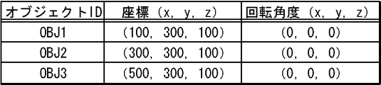
- FIG. 6 is a solid object position information management table for managing the solid object position information stored in the solid object position information storage unit 103.
- the three-dimensional object position information management table has items of “object ID”, “coordinates (x, y, z)”, and “rotation angle (x, y, z)”.
- the “object ID” is identification information for identifying a three-dimensional object, and corresponds to the “object ID” of the shape information described above.
- Coordinats (x, y, z)” is information indicating the coordinates at which the solid object indicated by the “object ID” of the same record is arranged.
- “Rotation angle (x, y, z)” indicates a rotation angle when the x-axis, y-axis, and z-axis of the three-dimensional object are the rotation axes.
- the width direction, the height direction, and the depth direction of the three-dimensional object are respectively the x-axis direction, the y-axis direction, and the z-axis in the virtual three-dimensional space. It shall be arranged parallel to the direction.
- the three-dimensional object position information is the two-dimensional information of the three-dimensional object. It may be information indicating coordinates on the background image or the like for indicating the position where the image is arranged. In this case, the three-dimensional object position information may be two-dimensional coordinate information, for example.
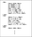
- FIG. 7 is a diagram showing the placement information stored in the placement information storage unit 102.
- the placement information forms data in XML format.
- the arrangement information does not have to be data in XML format, and may be data in a format in which the data can be referred to by item or attribute.
- each arrangement information is assumed to be tagged data, that is, data surrounded by a start tag and an end tag.
- the arrangement information is created and accumulated in advance by a user or the like.
- the placement information is grouped by product.
- a pair of product tags that is, tagged data in a range delimited by “ ⁇ product>” and “ ⁇ / product>” is information for arrangement of one product. If the information for specifying a file or the like, for example, link information is included as the placement information, the information on the file specified thereby is acquired by the image information configuration unit 105 as the placement information.
- FIG. 8 is a diagram showing an area designation information management table for managing area designation information.
- the area designation information management table has items of “object ID”, “surface”, and “synthesis mode change instruction”.
- the “object ID” is identification information for identifying a three-dimensional object, and corresponds to the “object ID” of the shape information described above.
- “Surface” is area designation information, and the area corresponding to this face on the image of the three-dimensional object is an area used for determining whether or not to output a compositing mode change instruction.
- the surface is indicated by the name of the surface of the three-dimensional object as shown in FIG.
- “Combination mode change instruction” is a composition mode change instruction. It is assumed that the area designation information management table is stored in advance in a storage unit such as the shape information storage unit 101, for example. Here, the area designation information is managed for each solid object, but one area designation information management table may be shared by a plurality of solid objects.
- the image information configuration unit 105 of the information processing apparatus 1 first displays the “object ID” shown in FIG. ”Is read as“ OBJ1 ”and temporarily stored in a memory or the like.
- the image information configuration unit 105 arranges the three-dimensional object from which the shape information has been read, that is, the three-dimensional object whose “object ID” is “OBJ1” (hereinafter referred to as the three-dimensional object “OBJ1”).
- the area information is acquired using the acquisition condition information as follows.
- the acquisition condition information of each surface constituting the solid object “OBJ1” is read from the acquisition condition information management table shown in FIG. 7 out of the arrangement information group specified by the value of the “corresponding group” attribute of the solid object “OBJ1” in the shape information management table shown in FIG. 3 among the arrangement information shown in FIG. Then, the placement information that matches the acquisition condition information of each surface is sequentially read out.
- “product name“ washing machine ”” that is the value of the “corresponding group” attribute of the three-dimensional object “OBJ1” is read from the shape information management table of FIG.
- This value means that the arrangement information group corresponding to the three-dimensional object “OBJ1” is a group including arrangement information whose element of the product name tag is “washing machine”.
- “price” which is the acquisition condition information of “X1 plane” in FIG. 5 is read.
- the information (element) to which the “price tag” is attached is read from the arrangement information group including the product name tag whose element is “washing machine” in the arrangement information shown in FIG. .
- the placement information including the product name tag whose element is “washing machine” is the tagged information within the range surrounded by the first product tag in FIG. 7, this product tag From the range surrounded by, the placement information which is text information “150,000 yen” with the price tag attached is read.
- the read information is temporarily stored in a storage medium or the like (not shown) in association with the X1 surface of the three-dimensional object “OBJ1”.
- arrangement information is acquired for other surfaces constituting the three-dimensional object “OBJ1”.
- the text information “washing machine” with the product name tag and the “washing machine red.gif”, “washing machine white.gif”, and “washing machine” tags with the “color” tag are attached.
- Image information “black.gif” is acquired as arrangement information.
- text information “Ox Electric” is acquired.
- the text information of the tag name of the placement information for example, “product name”, “specification”, “color”, “price”, etc. is obtained and the obtained placement information is acquired. You may set so that it may accumulate
- the image information configuration unit 105 determines the 3D object position information corresponding to the 3D object “OBJ1” from the 3D object position information management table shown in FIG. Is read. Specifically, “(100, 300, 100)” that is the value of “coordinate (x, y, z)” of the record whose “object ID” is “OBJ1”, and “rotation angle (x, y, z)”. z) ”(“ 0, 0, 0) ”is read out. Then, the image information configuration unit 105 configures the image information of the three-dimensional object “OBJ1” using the shape information of the three-dimensional object “OBJ1”.
- the position and orientation of the three-dimensional object “OBJ1” are set to be the position and orientation indicated by the object arrangement information read from the object arrangement information management table.
- the placement information acquired by the image information configuration unit 105 using the acquisition condition information specified for each surface is placed on each surface of the three-dimensional object “OBJ1”.
- the coordinate axes are set so that a projection view of the three-dimensional object is configured.
- the image information composing unit 105 reads out information indicating an image mode designated by default from a storage unit or the like (not shown). For example, here, it is assumed that the image mode specified by default indicated by the read information is “a mode in which images before and after are combined with 0% transparency”, that is, a mode in which images are combined so as to be opaque.
- the image information configuration unit 105 renders the shape information by arranging the placement information so that each surface of the three-dimensional object “OBJ1” is opaque.
- the image information configuration unit 105 sets the background to white, and the corresponding placement information To render each side of the 3D object opaque.
- drawing is not performed at all on the image of the back side of the surface of the 3D object that overlaps when viewed from the viewpoint of rendering.
- the X2, Y2, and Z2 planes are located behind the X1, Y1, and Z1 planes. Therefore, the images of these surfaces are not included at all in the generated image. Note that, since it is a well-known technique to determine the front-to-back relationship of surfaces or to perform synthesis using a designated synthesis mode at the time of rendering or the like, detailed description thereof is omitted here.
- the image information of the three-dimensional object is similarly configured for other three-dimensional objects.
- the image information configuration unit 105 further combines the configured images of the three-dimensional object on the background image specified by default or the like to configure image information including the three-dimensional object.
- the output unit 106 outputs the image information synthesized by the image information configuration unit 105.
- the output unit 106 includes a monitor 500 and displays image information of the three-dimensional object on the monitor 500.
- FIG. 9 shows a display example.
- the solid object 501 is a solid object “OBJ1”
- the solid object 502 is a solid object “OBJ2”
- the solid object 503 is a solid object “OBJ3”.
- the coordinate values and the positions of the three-dimensional objects shown in the figure are for explanation, and are not accurately drawn according to the actual size. This is the same in other embodiments.
- each solid object corresponds to a product, and an image for each product color, specifications, price, and the like are displayed on the surface of each solid object. It is possible to easily grasp the correspondence between the product and the specification information related to the product.
- the user touches the surface on which the product name is displayed on the image of the three-dimensional object 501 that is the three-dimensional object “OBJ1” displayed on the monitor 500 with a finger or the like.
- the screen of the information processing apparatus 1 is provided with a transparent touch panel, and coordinate information corresponding to the touched position is input to the position designation information receiving unit 1041 from the touch panel.
- the position designation information receiving unit 1041 receives position designation information corresponding to the position touched by the user. For example, assume that the coordinate information received here is (Xa, Ya).
- the combination mode acquisition unit 1042 indicates that the coordinate information of the position touched by the user indicated by the position specification information received by the position specification information receiving unit 1041 is the area specification information managed by the area specification information management table shown in FIG. It is determined whether or not it is located on any one of the designated areas.
- FIG. 11 is a diagram schematically showing the area indicated by the area designation information managed by the area designation information management table shown in FIG. 8 superimposed on the image output by the output unit 106.
- the hatched portion is the area indicated by the area designation information.
- the area 81 is an area corresponding to the surface “Z1 surface” of the solid object having the object ID “OBJ01”.
- the area 82 is an area corresponding to the surface “X1 surface” of the solid object having the object ID “OBJ02”.
- the region 83 is a region corresponding to the surface “X1 surface” of the solid object having the object ID “OBJ1”.
- the synthesis mode acquisition unit 1042 acquires the coordinate information indicating the “surface” shown in FIG. 8 in the rendered image, that is, the coordinate information indicating the region corresponding to the region designation information, from the rendering result of the image information configuration unit 105, for example. .
- This coordinate information may be the coordinate information of all the pixels constituting the area corresponding to the “surface”, or the coordinate information of the outline of the area corresponding to the “surface”.
- the image information configuration unit 105 manages, for example, each area and information on a set of “face” and “object ID” corresponding to each area in association with each other.
- the synthesis mode acquisition unit 1042 selects one of the one or more areas indicated by the area designation information as the position indicated by the coordinate information (Xa, Ya) that is the position designation information received by the position designation information reception unit 1041. It is determined whether it is one on the area.
- the compositing mode acquisition unit 1042 determines that the coordinate information (Xa, Ya) is the position on the area 81 specified by the area specifying information corresponding to the solid object whose object ID is “OBJ1”, that is, the object ID. Is determined to be a position on the area 81 corresponding to the surface “Y1 surface” of the solid object having “OBJ01”.
- the synthesis mode acquisition unit 1042 determines whether or not the position indicated by the position designation information received immediately before is a position on the same area 81.
- position designation information since position designation information has not been received before, it is determined that a position on the same area 81 has not been designated. If a position on the same area 81 is designated, it is preferable not to perform a process for outputting a synthesis mode change instruction as will be described later. This is to prevent the composite mode change instruction from being repeatedly acquired.
- the synthesis mode acquisition unit 1042 acquires the “synthesis mode” and “object ID” corresponding to the area designation information corresponding to the area 81 from the area designation information management table shown in FIG. Specifically, in the area designation information management table shown in FIG. 8, a record corresponding to the arrangement area 81, that is, a record whose object ID is “OBJ01” and “face” is “Z1 face” is detected. A set of a value of “synthesis mode” and a value of “object ID” included in the record is acquired. Here, “transparency 50%” is acquired as the value of “synthesis mode”, and “OBJ01” is acquired as the value of “object ID”.
- the composition mode acquisition unit 1042 finally changes from the acquired information “the composition mode when compositing the three-dimensional object with the object ID“ OBJ01 ”to the composition mode that transmits with a transparency of 50%.
- An image mode change instruction for instructing “to do” is acquired.
- the instruction acquired here may actually be considered as a command or the like.
- This process may be considered as a process of resetting the synthesis mode of other solid objects except the object ID “OBJ01” to the default synthesis mode. As a result, the image of the three-dimensional object that was displayed immediately before the composition mode was changed is displayed in the default composition mode.
- the image information configuration unit 105 configures the image information of the three-dimensional object using the shape information, the placement information, the three-dimensional object position information, and the like, as described above.
- an image mode change instruction for instructing to “change the composition mode when compositing the solid object having the object ID“ OBJ01 ”to a composition mode that transmits with a transparency of 50%” is acquired. Since the means 1042 has acquired, for the object whose object ID is “OBJ01”, in accordance with this image mode change instruction, the image mode is changed to “synthesizing mode in which the transparency is set to 50%” and the image is configured. To do.
- the image information configuration unit 105 renders the shape information by arranging the placement information so that the transparency of each surface of the solid object “OBJ1” is 50%.
- the background color of each surface of the three-dimensional object indicated by the shape information is set to, for example, white by default
- the image information configuration unit 105 sets the background to white, and the corresponding placement information To render all surfaces of the solid object so that the transparency is 50%.
- the image of the back side of the surface of the 3D object that is overlapped when viewed from the viewpoint of rendering is drawn so that a part of the surface arranged on the front side can be seen through. Is done.
- each surface is made opaque as described above.
- Image information a description is given of a case where the information arranged on the X2 plane and the Z2 plane is arranged so as to be easy to see when viewed from the viewpoint of rendering.
- information arranged on the X2 plane or the Z2 plane is obtained by inverting the information shown in FIG. Arranged in the direction.
- FIG. 12 shows an output example of the image information configured as described above. As shown in FIG. 12, for a three-dimensional object touched with a finger, an image on the back side of the three-dimensional object that could not be seen by opaque composition can be viewed from the front side.
- the compositing mode is changed depending on whether or not the position indicated by the position specifying information exists on the area indicated by the area specifying information.
- the image of the three-dimensional object is changed.
- An example in which the composition mode is changed according to the distance from the position indicated by the position designation information will be described. As shown in FIG. 9, the process is the same as that in the above specific example until the solid object is displayed.
- the position designation information receiving means 1041 acquires coordinate information of the touched position.
- the synthesis mode acquisition unit 1042 calculates coordinates indicating the position of each solid object (for example, the center position of each solid object), and the distance between the coordinates indicating the position of each solid object and the coordinates indicated by the position designation information Are calculated for each solid object. Then, a synthesis mode change instruction for changing the synthesis mode of each three-dimensional object to the transmission mode with the reciprocal of the calculated distance as the transparency is acquired. By using the reciprocal of the distance, the transparency of the three-dimensional object displayed at a position away from the touched position is set to be low.
- the image information configuration unit 105 configures the image information of the 3D object created by combining in accordance with the combining mode change instruction acquired for each 3D object.
- FIG. 14 shows an output example of the image information configured as described above.
- the transparency of the solid object 501 close to the touched position is high
- the transparency of the solid object 503 farthest from the touched position is the lowest
- the distance from the touched position is an intermediate transparency between the three-dimensional object 501 and the three-dimensional object 503.
- the transparency of the three-dimensional object can be changed continuously or in multiple stages according to the position on the image designated by the user with a finger or the like and the distance to each three-dimensional object. it can. Accordingly, it is possible to interactively and intuitively change the transparency of the three-dimensional object to be transmitted at a position designated by the user. Needless to say, instead of the reciprocal of the distance, another arithmetic expression using the distance as a variable may be used in accordance with the application.
- the position designation information indicates The transparency may be lowered when the position is on the solid object or close to the solid object.
- the present embodiment it is possible to appropriately display a solid object by changing the composition mode of the surface of the solid object in accordance with the compositing mode change instruction. For this reason, for example, by switching the composition mode, it is possible to make the arrangement information arranged on the back surface of the three-dimensional object visible or not visible from the front side.
- the compositing mode can be changed interactively.
- the position indicated by the position designation information is on the solid object or when the composition mode is changed when the position is close to the solid object, for example, when the solid object is operable, Since the synthesis mode of the solid object to be operated can be changed, the trouble of switching the synthesis mode becomes unnecessary, and the operability is improved.
- the information processing apparatus 1 can be used as a new user interface model, a new file system, and a new window system that can output information that can be defined in many ways.
- a solid object image or the like output by the information processing apparatus 1 may be used as an input interface image or the like for receiving an instruction or the like for performing other processing.
- the image information configuration unit 105 or a processing unit (not shown) is used.
- the shape information corresponding to the placement information received by the receiving unit (not shown) that receives the placement information stored in the placement information storage unit 102 or the placement information stored in the placement information storage unit 102 May be acquired by generation or reading, and image information for output may be configured using the acquired shape information.
- an image information configuration unit or a processing unit (not shown) acquires information on the number of pieces of surface information to be placed on the three-dimensional object from the placement information received by a receiving unit (not shown) that receives the placement information.
- n is an integer greater than or equal to 2
- the value of n may be used to automatically generate shape information of an n-hedron, for example, a regular n-hedron.
- template information or the like of n-face shape information prepared in advance may be read.
- An algorithm or the like constituting such a regular n-hedron may be stored in advance in a storage medium (not shown) and read out when necessary. This also applies to other embodiments.
- each process may be realized by centralized processing by a single device (system), or by distributed processing by a plurality of devices. May be.
- two or more communication means such as an information transmission unit
- two or more communication means existing in one apparatus may be physically realized by one medium.
- information related to processing executed by each component for example, information received, acquired, selected, generated, transmitted, and received by each component.
- information such as threshold values, mathematical formulas, addresses, etc. used by each component in processing is retained temporarily or over a long period of time on a recording medium (not shown) even when not explicitly stated in the above description. It may be.
- the storage of information in the recording medium (not shown) may be performed by each component or a storage unit (not shown).
- reading of information from the recording medium (not shown) may be performed by each component or a reading unit (not shown).
- the information processing apparatus may be a stand-alone apparatus or a server apparatus in a server / client system.
- the output unit or the reception unit receives an input or outputs a screen via a communication line.
- each component may be configured by dedicated hardware, or a component that can be realized by software may be realized by executing a program.
- each component can be realized by a program execution unit such as a CPU reading and executing a software program recorded on a recording medium such as a hard disk or a semiconductor memory.
- the software that realizes the information processing apparatus in each of the above embodiments is a program as described below. That is, the program includes a synthesis mode change instruction acquisition unit that acquires a synthesis mode change instruction that is an instruction to change a synthesis mode for at least the front and back surfaces of the surfaces constituting the solid object.
- Shape information that is information for designating the shape of a three-dimensional object that is a three-dimensional object stored in the shape information storage unit and one or more surfaces that constitute the three-dimensional object stored in the arrangement information storage unit
- Information for placement that is one or more pieces of information that can be placed on one or more faces of the three-dimensional object, and corresponding to each of the one or more faces of the read three-dimensional object Image information in which the placement information is arranged, and at least an image of a surface that overlaps the front and rear is changed in the synthesis mode
- an image information forming unit constituting the synthesized image information in accordance with the synthesis mode shows instructs to change a program for the image information configuration unit is to function as an output unit for outputting the image information constructed.
- the functions realized by the program do not include functions that can only be realized by hardware.
- functions that can be realized only by hardware such as a modem and an interface card in an acquisition unit that acquires information, an output unit that outputs information, and the like are not included in the functions realized by the program.
- the computer that executes this program may be singular or plural. That is, centralized processing may be performed, or distributed processing may be performed.
- FIG. 15 is a schematic diagram showing an example of an external appearance of a computer that executes the program and realizes the information processing apparatus according to the embodiment.
- the above-described embodiment can be realized by computer hardware and a computer program executed on the computer hardware.
- a computer system 900 includes a computer 901 including a CD-ROM (Compact Read Only Memory) drive 905 and an FD (Floppy (registered trademark) Disk) drive 906, a keyboard 902, a mouse 903, a monitor 904, and the like. Is provided.
- a computer 901 including a CD-ROM (Compact Read Only Memory) drive 905 and an FD (Floppy (registered trademark) Disk) drive 906, a keyboard 902, a mouse 903, a monitor 904, and the like.
- FIG. 16 is a diagram showing an internal configuration of the computer system 900.
- a computer 901 in addition to the CD-ROM drive 905 and the FD drive 906, a computer 901 is connected to an MPU (Micro Processing Unit) 911, a ROM 912 for storing a program such as a bootup program, and the MPU 911.
- MPU Micro Processing Unit
- ROM Read Only Memory
- a RAM Random Access Memory
- a hard disk 914 that stores application programs, system programs, and data
- an MPU 911 and a ROM 912 are interconnected.
- a bus 915 The computer 901 may include a network card (not shown) that provides connection to the LAN.
- a program that causes the computer system 900 to execute the functions of the information processing apparatus according to the above-described embodiment is stored in the CD-ROM 921 or the FD 922, inserted into the CD-ROM drive 905 or the FD drive 906, and transferred to the hard disk 914. May be. Instead, the program may be transmitted to the computer 901 via a network (not shown) and stored in the hard disk 914. The program is loaded into the RAM 913 when executed. The program may be loaded directly from the CD-ROM 921, the FD 922, or the network.
- the program does not necessarily include an operating system (OS) or a third-party program that causes the computer 901 to execute the functions of the information processing apparatus according to the above embodiment.
- the program may include only a part of an instruction that calls an appropriate function (module) in a controlled manner and obtains a desired result. How the computer system 900 operates is well known and will not be described in detail.
- the information processing apparatus is suitable as an apparatus for outputting information, and is particularly useful as an apparatus for arranging and outputting information on a three-dimensional object.
Landscapes
- Engineering & Computer Science (AREA)
- General Engineering & Computer Science (AREA)
- Theoretical Computer Science (AREA)
- Human Computer Interaction (AREA)
- Physics & Mathematics (AREA)
- General Physics & Mathematics (AREA)
- User Interface Of Digital Computer (AREA)
- Image Generation (AREA)
- Processing Or Creating Images (AREA)
Abstract
Les dispositifs de traitement d'informations conventionnels sont problématiques du fait qu'un objet en trois dimensions ne peut pas être affiché correctement.
La présente invention concerne un dispositif de traitement d'informations comportant une section de stockage d'informations de forme (101) dans laquelle des ensembles d'informations de forme d'objets en trois dimensions peuvent être stockés, une section de stockage d'information d'agencement (102) dans laquelle des ensembles d'informations d'agencement agencés sur les surfaces des objets en trois dimensions peuvent être stockés, une section d'acquisition d'instruction de changement à mode combiné (104) pour obtenir une instruction de changement de mode combiné au niveau d'au moins des surfaces qui se chevauchent devant et derrière parmi les surfaces des objets en trois dimensions, une section de configuration d'informations d'image (105) pour lire les ensembles d'informations de forme des objets en trois dimensions et les ensembles d'informations d'agencement agencés sur les surfaces des objets en trois dimensions et configurer des informations d'image, qui sont les informations d'image dans lesquelles un ensemble d'informations d'agencement correspondant à chacune des surfaces des objets en trois dimensions est agencé sur celle-ci, et dans lesquelles les images des surfaces qui se chevauchent devant et derrière sont combinées selon le mode combiné stipulé par l'instruction de changement de mode combiné et une section de sortie (106) pour fournir en sortie l'information d'image configurée.
Applications Claiming Priority (2)
| Application Number | Priority Date | Filing Date | Title |
|---|---|---|---|
| JP2009-101267 | 2009-04-17 | ||
| JP2009101267A JP5175794B2 (ja) | 2009-04-17 | 2009-04-17 | 情報処理装置、情報処理方法、およびプログラム |
Publications (1)
| Publication Number | Publication Date |
|---|---|
| WO2010119829A1 true WO2010119829A1 (fr) | 2010-10-21 |
Family
ID=42982491
Family Applications (1)
| Application Number | Title | Priority Date | Filing Date |
|---|---|---|---|
| PCT/JP2010/056505 Ceased WO2010119829A1 (fr) | 2009-04-17 | 2010-04-12 | Dispositif de traitement d'informations, procédé de traitement d'informations et programme |
Country Status (2)
| Country | Link |
|---|---|
| JP (1) | JP5175794B2 (fr) |
| WO (1) | WO2010119829A1 (fr) |
Families Citing this family (4)
| Publication number | Priority date | Publication date | Assignee | Title |
|---|---|---|---|---|
| JP5924325B2 (ja) * | 2013-10-02 | 2016-05-25 | コニカミノルタ株式会社 | 入力装置、情報処理装置、入力装置の制御方法、および、当該制御方法をコンピューターに実行させるためのプログラム |
| JP6344006B2 (ja) * | 2014-03-28 | 2018-06-20 | カシオ計算機株式会社 | 携帯情報機器、携帯情報機器におけるオブジェクトの報知方法、及び携帯情報機器のプログラム |
| JP6638761B2 (ja) * | 2018-05-15 | 2020-01-29 | カシオ計算機株式会社 | 情報機器、情報機器におけるオブジェクトの報知方法、及び情報機器のプログラム |
| EP3940577B1 (fr) * | 2020-07-15 | 2025-09-10 | Dassault Systèmes | Procédé de conception d'une maille tridimensionnelle dans une scène en 3d |
Citations (4)
| Publication number | Priority date | Publication date | Assignee | Title |
|---|---|---|---|---|
| JP2002230577A (ja) * | 2001-01-30 | 2002-08-16 | Namco Ltd | ゲーム装置および情報記憶媒体 |
| WO2002069276A1 (fr) * | 2001-02-23 | 2002-09-06 | Fujitsu Limited | Dispositif de commande d'affichage, dispositif terminal d'information equipe de ce dispositif de commande d'affichage, et dispositif de commande de position de point de vue |
| WO2005098761A1 (fr) * | 2004-03-30 | 2005-10-20 | Lexer Research Inc. | Dispositif d’affichage d’objet et programme d’affichage d’objet |
| JP2006039872A (ja) * | 2004-07-26 | 2006-02-09 | Canon Inc | 情報処理方法及び情報処理装置 |
-
2009
- 2009-04-17 JP JP2009101267A patent/JP5175794B2/ja not_active Expired - Fee Related
-
2010
- 2010-04-12 WO PCT/JP2010/056505 patent/WO2010119829A1/fr not_active Ceased
Patent Citations (4)
| Publication number | Priority date | Publication date | Assignee | Title |
|---|---|---|---|---|
| JP2002230577A (ja) * | 2001-01-30 | 2002-08-16 | Namco Ltd | ゲーム装置および情報記憶媒体 |
| WO2002069276A1 (fr) * | 2001-02-23 | 2002-09-06 | Fujitsu Limited | Dispositif de commande d'affichage, dispositif terminal d'information equipe de ce dispositif de commande d'affichage, et dispositif de commande de position de point de vue |
| WO2005098761A1 (fr) * | 2004-03-30 | 2005-10-20 | Lexer Research Inc. | Dispositif d’affichage d’objet et programme d’affichage d’objet |
| JP2006039872A (ja) * | 2004-07-26 | 2006-02-09 | Canon Inc | 情報処理方法及び情報処理装置 |
Also Published As
| Publication number | Publication date |
|---|---|
| JP5175794B2 (ja) | 2013-04-03 |
| JP2010250696A (ja) | 2010-11-04 |
Similar Documents
| Publication | Publication Date | Title |
|---|---|---|
| JP5513071B2 (ja) | 情報処理装置、情報処理方法、およびプログラム | |
| US8264488B2 (en) | Information processing apparatus, information processing method, and program | |
| JP5566632B2 (ja) | 情報処理装置、情報処理方法、およびプログラム | |
| CN110163942B (zh) | 一种图像数据处理方法和装置 | |
| CN101038679B (zh) | 几何数据处理方法和装置以及部件目录系统 | |
| JP5592011B2 (ja) | マルチスケール3次元配向 | |
| WO2005069170A1 (fr) | Dispositif d'affichage d'une liste de fichiers d'images | |
| CN103975365A (zh) | 用于俘获和移动真实世界对象的3d模型和真实比例元数据的方法和系统 | |
| WO2007123009A1 (fr) | Dispositif de navigation d'image, procédé de commande par ordinateur et support d'enregistrement des informations | |
| WO2010150768A1 (fr) | Dispositif de traitement de données, procédé de traitement de données et programme | |
| WO2011129122A1 (fr) | Livre électronique permettant de fournir à une communauté les pages qu'il contient | |
| JP5175794B2 (ja) | 情報処理装置、情報処理方法、およびプログラム | |
| JP5372590B2 (ja) | 情報処理装置、情報処理方法、およびプログラム | |
| CN107481307B (zh) | 一种快速渲染三维场景的方法 | |
| CN117788609A (zh) | 界面图元的拾取方法、装置、设备及存储介质 | |
| US9043707B2 (en) | Configurable viewcube controller | |
| CN107704483A (zh) | 一种三维模型的加载方法 | |
| CN107481306B (zh) | 一种三维交互的方法 | |
| JP5509015B2 (ja) | 電力情報表示装置 | |
| JP5038250B2 (ja) | 情報処理装置、情報処理方法、およびプログラム | |
| CN118710360A (zh) | 场景的信息处理方法、系统、电子设备、存储介质和程序产品 | |
| US9734579B1 (en) | Three-dimensional models visual differential | |
| JP5862223B2 (ja) | パーツカタログ作成装置、プログラム、およびパーツカタログ作成方法 | |
| CN114820968A (zh) | 三维可视化方法和装置、机器人、电子设备和存储介质 | |
| CN107688599B (zh) | 一种快速检索三维模型的方法 |
Legal Events
| Date | Code | Title | Description |
|---|---|---|---|
| 121 | Ep: the epo has been informed by wipo that ep was designated in this application |
Ref document number: 10764413 Country of ref document: EP Kind code of ref document: A1 |
|
| NENP | Non-entry into the national phase |
Ref country code: DE |
|
| 122 | Ep: pct application non-entry in european phase |
Ref document number: 10764413 Country of ref document: EP Kind code of ref document: A1 |