WO2010119829A1 - 情報処理装置、情報処理方法、およびプログラム - Google Patents
情報処理装置、情報処理方法、およびプログラム Download PDFInfo
- Publication number
- WO2010119829A1 WO2010119829A1 PCT/JP2010/056505 JP2010056505W WO2010119829A1 WO 2010119829 A1 WO2010119829 A1 WO 2010119829A1 JP 2010056505 W JP2010056505 W JP 2010056505W WO 2010119829 A1 WO2010119829 A1 WO 2010119829A1
- Authority
- WO
- WIPO (PCT)
- Prior art keywords
- information
- dimensional object
- image
- change instruction
- mode
- Prior art date
- Legal status (The legal status is an assumption and is not a legal conclusion. Google has not performed a legal analysis and makes no representation as to the accuracy of the status listed.)
- Ceased
Links
Images


Classifications
-
- G—PHYSICS
- G06—COMPUTING OR CALCULATING; COUNTING
- G06F—ELECTRIC DIGITAL DATA PROCESSING
- G06F3/00—Input arrangements for transferring data to be processed into a form capable of being handled by the computer; Output arrangements for transferring data from processing unit to output unit, e.g. interface arrangements
- G06F3/01—Input arrangements or combined input and output arrangements for interaction between user and computer
- G06F3/048—Interaction techniques based on graphical user interfaces [GUI]
- G06F3/0481—Interaction techniques based on graphical user interfaces [GUI] based on specific properties of the displayed interaction object or a metaphor-based environment, e.g. interaction with desktop elements like windows or icons, or assisted by a cursor's changing behaviour or appearance
-
- G—PHYSICS
- G06—COMPUTING OR CALCULATING; COUNTING
- G06F—ELECTRIC DIGITAL DATA PROCESSING
- G06F3/00—Input arrangements for transferring data to be processed into a form capable of being handled by the computer; Output arrangements for transferring data from processing unit to output unit, e.g. interface arrangements
- G06F3/01—Input arrangements or combined input and output arrangements for interaction between user and computer
- G06F3/048—Interaction techniques based on graphical user interfaces [GUI]
- G06F3/0487—Interaction techniques based on graphical user interfaces [GUI] using specific features provided by the input device, e.g. functions controlled by the rotation of a mouse with dual sensing arrangements, or of the nature of the input device, e.g. tap gestures based on pressure sensed by a digitiser
- G06F3/0488—Interaction techniques based on graphical user interfaces [GUI] using specific features provided by the input device, e.g. functions controlled by the rotation of a mouse with dual sensing arrangements, or of the nature of the input device, e.g. tap gestures based on pressure sensed by a digitiser using a touch-screen or digitiser, e.g. input of commands through traced gestures
-
- G—PHYSICS
- G06—COMPUTING OR CALCULATING; COUNTING
- G06F—ELECTRIC DIGITAL DATA PROCESSING
- G06F2203/00—Indexing scheme relating to G06F3/00 - G06F3/048
- G06F2203/048—Indexing scheme relating to G06F3/048
- G06F2203/04802—3D-info-object: information is displayed on the internal or external surface of a three dimensional manipulable object, e.g. on the faces of a cube that can be rotated by the user
Definitions
- the present invention relates to an information processing apparatus that displays a three-dimensional image or the like.
- a menu item is assigned to each area of a three-dimensional figure, a display step for displaying the three-dimensional figure, a movement step for moving the three-dimensional figure according to an instruction command to be input, and an assignment to the three-dimensional figure
- a three-dimensional menu selection method comprising: a selection step for selecting a required menu from a given menu item; and a selection processing execution step for executing processing corresponding to the selected menu.
- JP-A-7-114451 (first page, FIG. 1 etc.)
- the back surface of the three-dimensional object overlaps with the front portion of the three-dimensional object and is hidden behind the front surface. For this reason, the subject that the back of a solid object cannot be displayed occurred. For this reason, in order to view the image on the back of the three-dimensional object, it is necessary to rotate the three-dimensional object, which takes time and effort and is not convenient.
- each surface of the 3D object is displayed transparently, it is possible to visually recognize what information is arranged on the back of the 3D object without operating the 3D object. Is possible.
- the rear image is combined with the front image and displayed, there is a problem that it becomes difficult to grasp the front information. For example, when there is no need to see the back image, the back image simply becomes an image that hinders the visibility of the front image.
- An information processing apparatus is arranged on a shape information storage unit that can store shape information that is information for designating the shape of a three-dimensional object that is a three-dimensional object, and 1 arranged on one or more surfaces constituting the three-dimensional object.
- An arrangement information storage unit that can store arrangement information that is the above information, and a composition mode change instruction that is an instruction to change the composition mode for at least the front and back of the surfaces constituting the solid object.
- An information processing apparatus comprising: an image information configuration unit that configures image information synthesized according to a synthesis mode in which a composition mode change instruction instructs a change; and an output unit that outputs image information configured by the image information configuration unit is there.
- the 3D object can be displayed appropriately by switching the synthesis mode of the surfaces constituting the 3D object.
- the arrangement information arranged on the back surface of the three-dimensional object can be made visible or invisible from the front side. Visibility can be improved.
- the composition mode change instruction is an instruction to change transparency
- the image information configuration unit includes: This is an information processing apparatus that configures image information in which the transparency of at least a surface disposed in front of at least the front and back overlapping surfaces is changed.
- the 3D object can be appropriately displayed by switching the synthesis mode for the transparency of the surfaces constituting the 3D object. Accordingly, for example, by switching the composition mode for transparency, it is possible to appropriately transmit the front surface of the three-dimensional object so that the arrangement information arranged on the back surface of the three-dimensional object can be viewed from the front side. Or can be switched from being visually recognized, and the visibility of the three-dimensional object can be improved according to the situation.
- the composition mode change instruction receiving unit includes position specifying information receiving means for receiving position specifying information that is information for specifying a position of an image indicated by the image information.
- An information processing apparatus comprising: a synthesis mode acquisition unit configured to acquire a synthesis mode change instruction for the three-dimensional object according to a positional relationship between the position designated by the position designation information and the position of the three-dimensional object in the image information. It is.
- the information processing apparatus is the information processing apparatus, wherein the synthesis mode acquisition unit acquires a synthesis mode change instruction that designates one of two or more different synthesis modes according to the positional relationship. Device.
- the composition mode can be switched and displayed.
- the synthesis mode acquisition unit determines whether the position specified by the position specifying information is a position in a predetermined area on the three-dimensional object. It is an information processing apparatus that detects and acquires a compositing mode change instruction for the solid object according to the detection result.
- the information processing apparatus or the like it is possible to switch the composition mode of the surfaces constituting the three-dimensional object and display the three-dimensional object appropriately.
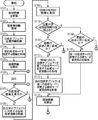
- the block diagram of the information processing apparatus concerning embodiment of this invention Flow chart for explaining the operation of the information processing apparatus
- movement of the information processing apparatus The figure for demonstrating the name of each surface of a solid object for demonstrating operation
- movement of the information processing apparatus The figure which shows the acquisition condition information management table for demonstrating operation
- movement of the information processing apparatus The figure which shows the area
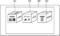
- the figure which shows the example of a display by the information processing apparatus The figure which shows the operation condition for demonstrating operation
- region designation information shows in order to demonstrate operation
- the figure which shows the output example of the information processing apparatus The figure which shows the operation condition for demonstrating operation
- the figure which shows the output example of the information processing apparatus Schematic diagram showing an example of the external appearance of the computer system
- FIG. 1 is a block diagram of an information processing apparatus 1 in the present embodiment.
- the information processing apparatus 1 includes a shape information storage unit 101, an arrangement information storage unit 102, a three-dimensional object position information storage unit 103, a synthesis mode change instruction acquisition unit 104, an image information configuration unit 105, and an output unit 106.
- the composition mode change instruction acquisition unit 104 includes position designation information reception means 1041 and composition mode acquisition means 1042.
- the information processing apparatus 1 includes, for example, a computer, a mobile phone, a PDA (personal digital assistant), a high-function mobile phone that combines a mobile phone and an information terminal, a portable digital music player, a television, and the like.
- Information devices such as audio-visual devices having a display device. The same applies to other embodiments.
- the shape information storage unit 101 can store shape information that is information specifying the shape of a three-dimensional object that is a three-dimensional object.
- the shape information is information that defines the shape or the like of an object arranged in the virtual three-dimensional space.
- the shape information is so-called modeling information of a three-dimensional object, for example.
- the three-dimensional object described here includes, for example, what is called a 3D object, a 3D model, or a three-dimensional model.
- the shape information is information on the coordinates of the vertices of the three-dimensional object, information on parameters of equations that express boundary lines, surfaces, and the like.
- a solid object usually has information that defines a surface or information that can define a surface, and is composed of one or more surfaces.
- the three-dimensional object can be classified into polygon modeling, modeling using a free-form surface, and the like, for example, depending on the method of constructing the surface.
- the shape information may include information on setting items such as the color of the 3D object, transparency, reflection, refractive index, and bump when the 3D object is output.
- the shape information storage unit 101 can store shape information of one or more solid objects.
- the shape of the three-dimensional object may be any shape such as a sphere, a cylinder, a polyhedron such as a hexahedron or an octahedron, a cube, a cone, or a pyramid.
- a unit such as a size of the shape information may be an absolute unit or a relative unit.
- the shape information storage unit 101 is preferably a non-volatile recording medium, but can also be realized by a volatile recording medium.
- the placement information storage unit 102 can store placement information that is one or more pieces of information that can be placed on the surfaces constituting the three-dimensional object.
- the placement information may be any information such as image information such as a still image and a moving image, text information, and the like as long as it is information that can be output and displayed, for example, by placing it on the surface constituting the solid object.
- the arrangement described here may be considered as mapping of image information or the like on the surface of a so-called solid object.
- the arrangement information may be considered as information to be mapped, for example, texture information.
- the data structure of the placement information is not limited.
- the placement information may be tagged information.
- the placement information may be information managed in association with attributes or the like by using a table or a database. Further, the placement information may be grouped in advance.
- the arrangement information may be associated with the surface of the three-dimensional object on which the arrangement information is arranged.
- management information or the like that manages a set of placement information or its identification information and a surface of the solid object associated with the placement information or its identification information as a plurality of items of one record May be.
- This management information may be stored in a storage unit (not shown), for example.
- the shape information storage unit 101 and the placement information storage unit 102 are configured as a single storage unit, and the information indicating the surface of the three-dimensional object indicated by the shape information corresponds to the placement information placed on the surface. It may be attached and stored.
- the shape information storage unit 101 or the like is associated with the surface of the solid object indicated by the shape information in association with acquisition condition information or the like indicating information for acquiring the placement information arranged on the surface. May be stored.
- the acquisition condition information is, for example, information indicating a search condition such as a search expression for searching for placement information arranged on a surface. In this case, by performing a search using information such as a search expression associated with each surface, it is possible to acquire the placement information placed on the surface.
- the information acquisition condition information may be any information as long as it is information that can eventually designate one or more pieces of placement information arranged on the surface of one or more solid objects.
- the acquisition condition information may be information specifying the item.
- the placement information has an attribute, it may be information specifying the attribute.
- the placement information is tagged, it may be information specifying a tag name.
- index information is added to the placement information, information for designating the index may be used.
- it may be information designating the location, file name, directory, etc. of the placement information.
- it may be a search expression or an arithmetic expression for searching the arrangement information.
- the search formula does not necessarily have to be shown in the form of a formula, and may be a keyword that can be used for the search.
- the acquisition condition information indicated by this search expression is a combination of “select”, “from”, “where”, and the like. Note that “select” is an item of information for arrangement to be acquired, “from” is information for specifying a plurality of pieces of information for arrangement to be searched, and “where” is information indicating conditions for search (SQL specification) See).
- the acquisition condition information indicated by the arithmetic expression is, for example, an arithmetic expression performed on one or more pieces of arrangement information, for example, information specifying two pieces of arrangement information represented by numerical values, and these Are expressed by an arithmetic expression for calculating the average of the above, an arithmetic expression for adding / subtracting a predetermined time to / from a current time, and the like.
- the acquisition condition information may be individually specified for all solid objects that can be output, or may be specified for all solid objects. Further, it may be specified in common for some solid objects. When an attribute or the like is set for a solid object, a common acquisition condition may be specified for a solid object that matches the attribute.
- the acquisition condition information may be specified in advance for each surface of the three-dimensional object, or may be specified randomly for each surface.
- the placement information storage unit 102 is preferably a non-volatile recording medium, but can also be realized by a volatile recording medium.
- three-dimensional object position information which is information for designating the position of the three-dimensional object
- the position described here is, for example, a position in the virtual three-dimensional space.
- the three-dimensional object position information may be position information on a two-dimensional plane.
- the three-dimensional object position information may include, for example, information indicating the direction in which the three-dimensional object is arranged, that is, the direction of the object, the size of the three-dimensional object, and the like in addition to the position of the three-dimensional object.
- the position of the three-dimensional object may be considered as, for example, the position of one or more parts in the three-dimensional object in the virtual three-dimensional space.
- the position of the three-dimensional object may be a position of one or more vertices, sides, or faces where the sides constituting the three-dimensional object are gathered, or may be a position such as the center or the center of gravity of the three-dimensional object.
- the three-dimensional object position information only needs to be information that can eventually specify the position of the three-dimensional object.
- the three-dimensional object position information is information that designates coordinates of a position where the three-dimensional object is arranged, for example.
- the position of the three-dimensional object is represented by coordinates, for example.
- the coordinates for designating the position of the three-dimensional object may be absolute coordinates set in a virtual three-dimensional space or the like, or may be relative coordinates set for another three-dimensional object or the like. good.
- the coordinates for designating the position of the three-dimensional object may be the coordinates of the vertices where the sides constituting the three-dimensional object gather, or the coordinates of the positions of the center and the center of gravity of the three-dimensional object.
- three-dimensional object position information and three-dimensional object shape information are provided for each of one or more three-dimensional objects, but the three-dimensional object position information may be included in the shape information.
- the position of the three-dimensional object can be specified using the shape information as the three-dimensional object position information.
- the shape information storage unit 101 and the three-dimensional object position information storage unit 103 may be configured by a single storage unit.
- the image information configuration unit 105 described later reads the solid object position information, and configures image information in which the solid object is positioned at a position in the virtual three-dimensional space indicated by the solid object position information.
- the three-dimensional object position information storage unit 103 is preferably a non-volatile recording medium, but can also be realized by a volatile recording medium.
- the composition mode change instruction acquisition unit 104 acquires a composition mode change instruction that is an instruction to change the composition mode for at least the front and back surfaces of the surfaces constituting the solid object.
- the synthesis mode change instruction may be considered as information indicating an instruction to change the synthesis mode with respect to the synthesis mode designated by default or the current synthesis mode.
- the composition mode change instruction may be an instruction to change the composition mode after the change to a composition mode different from the composition mode before the change, and includes information for explicitly specifying the composition mode after the change. It may or may not be included.
- the combination mode change instruction acquired by the combination mode change instruction acquisition unit 104 in the case of including information that explicitly specifies the changed combination mode is, for example, an instruction to change the combination mode to a mode that transmits at 90% transparency
- the synthesis mode change instruction acquired by the synthesis mode change instruction acquisition unit 104 when the information that explicitly specifies the changed synthesis mode is not included is, for example, an instruction to change to a synthesis mode different from the current synthesis mode, etc.
- Information indicating a synthesis mode different from that before the change may be considered as a synthesis mode change instruction.
- the 3D object compositing mode is, for example, a compositing method that indicates how to synthesize a front and back overlapping surface.
- this is a surface composition method that indicates how an image arranged on the front side is to be synthesized with an image arranged on the back side of the image.
- a pixel obtained by performing a predetermined calculation designated by the synthesis mode using values of pixels of images arranged on the overlapping surfaces is a synthesized pixel.
- the synthesis mode is also called, for example, a drawing mode.
- the composition mode is, for example, a mode in which an image is transmitted with a predetermined transparency and combined. In this case, the synthesis mode change instruction may be considered as an instruction to change the transparency.
- This combination mode change instruction may or may not have information for designating the transparency. If not, it can be considered as information specifying a synthesis mode for transmitting an image with a preset transparency.
- the transparency may be a value indicating transparency such as 0 to 100%, or may be qualitative data associated with a value indicating transparency such as “transparency” or “semi-transparency”. good. Note that when the transparency is 0%, that is, when the transmission is not performed, or when the transparency is 100%, that is, when the target image is not displayed, it may be considered as a transmission mode or a different mode. good.
- modes such as multiplication, overlay, and dither synthesis are known.
- composition modes In different composition modes, arithmetic expressions, parameters, and the like at the time of composition are different. A combination of the transmission mode and another synthesis mode may be considered as one of the synthesis modes. Since the synthesis mode and the processing for synthesizing images according to the synthesis mode are known techniques in 3D software, image processing software, and the like, description thereof is omitted here. Note that, in the present application, the composition mode instructed by the composition mode change instruction is a composition mode in which all or part of the back image can be transmitted so that the user can recognize the image from the front. Is preferred.
- the synthesis mode of the three-dimensional object is a method of indicating how to display an image placed on the front side with respect to an image placed on the back side of the image, or placed on the front side. Since it can be considered to be a display method for displaying an image and an image arranged on the back of the image in a superimposed manner, it may be considered as a display mode of a three-dimensional object.
- the front surface described here is specifically located forward, that is, on the viewpoint side when the virtual three-dimensional space of the surfaces constituting the three-dimensional object is viewed from a virtual viewpoint specified in advance. It is a surface to do.
- the viewpoint here is a viewpoint at the time of rendering or the like.
- the back surface is a surface located behind the front surface. Note that the side close to the surface of the screen on which the image of the three-dimensional object is displayed may be considered as the front surface.
- only the surface at least partially overlapping the front surface may be considered as the back surface.
- only the overlapping area may be considered as the back surface.
- the overlapped front portion may be considered the front surface and the overlapped rear portion may be considered the back surface.
- the compositing mode change instruction may be an instruction to change the compositing mode of overlapping surfaces in different three-dimensional objects. Further, the compositing mode change instruction may be considered to include an instruction to change the compositing mode with respect to the background image of the area where the solid object is arranged on each surface constituting the solid object. For example, when the first surface and the second surface are arranged in the virtual three-dimensional space, an instruction to change the composition mode of the three-dimensional object to the composition mode that transmits the image with 50% transparency is composed. When the mode change instruction is received, the transparency of the first surface and the second surface may be set to 50%, respectively, so that the background can be seen through. Alternatively, only the transmittance of the surface disposed on the front surface of the first surface and the second surface is changed to 50%, and the surface disposed on the back surface cannot be seen through. You may do it.
- the compositing mode change instruction may or may not include information for designating a three-dimensional object for which the compositing mode is to be changed and information for designating a surface of the three-dimensional object for which the compositing mode is to be changed.
- the composition mode of one or more pre-designated three-dimensional objects or a predesignated surface is changed when the image information composing unit 105 described later composes an image.
- the compositing mode change instruction for a solid object including another solid object inside, that is, a solid object having a nested structure may be considered as information for changing the compositing mode for the outer solid object. It may also be considered as information for changing the composition mode for both of the solid objects located inside.
- the synthesis mode change instruction acquisition unit 104 acquires, for example, a synthesis mode change instruction for changing the synthesis mode between two or more different synthesis modes.
- the different synthesis modes may mean that the synthesis modes themselves are different, or that parameters or the like are different in one synthesis mode.
- the multiplication mode and the overlay mode may be considered as different synthesis modes, or those with different parameter values used for synthesis in one synthesis mode may be considered as different synthesis modes. good.
- a mode in which an image is transmitted with different transparency such as a set of a mode in which an image is transmitted with 0% transparency and a mode in which an image is transmitted with 50% transparency, may be considered as different synthesis modes. good.
- the transparency or the like may be set to a value that makes it easy to see the synthesized image.
- the composition mode change instruction acquisition unit 104 uses a mouse, a keyboard, an input device such as a touch pad, or the like to operate a composite mode input by operating an input interface such as a button for switching a composition mode or an input menu. Accepting a mode change instruction may be considered as acquisition. Further, the synthesis mode change instruction acquisition unit 104 may acquire a synthesis mode change instruction corresponding to the relationship between the position where the solid object is displayed and the position on the display image specified by the user.
- “Reception” refers to reception of information input from an input device such as a keyboard, mouse, touch panel, reception of information transmitted via a wired or wireless communication line, an optical disk, a magnetic disk, a recording medium such as a semiconductor memory, etc. This is a concept including reception of information read out from.
- the input means may be anything such as a numeric keypad, keyboard, mouse or menu screen.
- the synthesis mode change instruction acquisition unit 104 can be realized by a device driver for input means such as a numeric keypad or a keyboard, control software for a menu screen, or the like.
- the combination mode change instruction acquisition unit 104 includes the position designation information reception unit 1041 and the combination mode acquisition unit 1042, and uses these to acquire a combination mode change instruction.
- the combination mode change instruction acquired by the combination mode acquisition unit 1042 may be considered as the combination mode change instruction acquired by the combination mode change instruction acquisition unit 104.
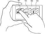
- the position designation information accepting unit 1041 accepts position designation information that is information for designating a position on the image indicated by the image information.
- the position designation information receiving unit 1041 designates the position on the image indicated by the image information output by the output unit 106, which will be described later, designated by the user or the like using an input unit such as a mouse, a keyboard, or a touch panel.
- Accept location specification information The information that designates the position on the image is information that designates a position where a pointer, a cursor, or the like exists, for example.
- it is information for designating a position touched by a finger on a touch panel or the like.
- the information specifying the position is, for example, coordinate information corresponding to the display screen or the displayed image information.
- the coordinate information received by the position designation information receiving unit 1041 may be coordinate information in a virtual three-dimensional space calculated from information on the position of a pointer or cursor.
- the position designation information accepting unit 1041 may accept position designation information about a position where a pointer, cursor or finger exists, for example, at a predetermined timing such as a predetermined time interval, or there is a pointer or cursor.
- the position designation information may be received when a predetermined operation such as a click on a mouse button or the like, a pressing of a predetermined key such as an Enter key, or a tap on a touch panel or the like with a finger is performed at the position to be performed. .
- the position specifying information input means may be anything such as a numeric keypad, a keyboard, a mouse, or a menu screen.
- the position designation information receiving unit 1041 can be realized by a device driver of an input unit such as a numeric keypad, a keyboard, or a touch panel, or control software for a menu screen.
- the compositing mode acquisition unit 1042 acquires a compositing mode change instruction for the three-dimensional object according to the positional relationship between the position specified by the position specifying information and the position of the three-dimensional object in the image information.
- the acquisition of the synthesis mode change instruction described here is, for example, reading of a synthesis mode change instruction, generation of a synthesis mode change instruction, or the like.
- the synthesis mode change instruction acquired here may be, for example, an instruction including information for designating the solid object used for determining the positional relationship when acquiring the synthesis mode change instruction as the synthesis mode change target.
- the combination mode acquisition unit 1042 acquires a combination mode change instruction that specifies one of two or more different combination modes according to the positional relationship.
- the acquisition of the compositing mode change instruction according to the positional relationship is, for example, the acquisition of the compositing mode change instruction according to the distance relationship between the position specified by the position specifying information and the position of the three-dimensional object. Further, it is also possible to acquire the compositing mode change instruction according to the detection result of whether or not the position specified by the position specifying information is a position in a predetermined area on the solid object.
- the composition mode acquisition unit 1042 acquires the position designated by the position designation information and the position information of one solid object in the image information, and the position designated by the position designation information and the image information from the position information. The distance from the position of one solid object at is calculated. Then, in accordance with the distance between the position designated by the position designation information and the position of the solid object in the image information, a synthesis mode change instruction for the solid object is acquired.
- Exceeding the threshold described here may mean that the distance is less than the threshold or more than the threshold, or may be that the distance is more than the threshold or less than the threshold. good.
- the synthesis mode acquisition unit 1042 switches to one of the two synthesis modes designated in advance and one of the synthesis modes other than the current synthesis mode.
- the composition mode change instruction for changing the composition mode of the three-dimensional object may be acquired.
- At least a part of values that can be taken by the distance between the position designated by the position designation information and the position of the three-dimensional object in the image information is preliminarily used in two or more stages.
- the distance between the position designated by the position designation information and the position of the one three-dimensional object in the image information so that information indicating different synthesis modes is associated with each stage is the above-mentioned 2.
- Information specifying the synthesis mode may be acquired as a synthesis mode change instruction for the three-dimensional object. This determination may be made only when the stage in which the distance is included changes.
- the composition mode of the three-dimensional object can be changed step by step as the position designated by the position designation information approaches the three-dimensional object.
- the synthesis mode change instruction is information specifying the transparency, that is, information specifying the synthesis mode for changing the transparency to the specified transparency, the higher the transparency is associated with the shorter distance.
- the transparency of the three-dimensional object can be increased stepwise.
- a range of one or more distance values bounded by one or more threshold values specified in advance and information indicating one or more synthesis modes are associated with each other in advance in a storage unit (not shown).
- a range of values with the threshold value as a boundary
- a combination mode conversion instruction for specifying a combination mode associated with a range of values including the distance between the position specified by the position specifying information and the position of the three-dimensional object in the image information may be acquired.
- the information indicating the synthesis mode associated with the range of distance values in this case may be information for specifying the synthesis mode, or specify one parameter of the synthesis mode, such as a transparency value. It may be information to do.
- the value of the distance between the position specified by the position specification information and the position of the solid object in the image information is assigned to a variable, it is possible to specify in advance a value such as a transparency value that can be calculated as a composite mode parameter.
- a predetermined function or the like is prepared in advance in a storage unit (not shown), and the value of the distance between the position designated by the position designation information and the position of the three-dimensional object in the image information is substituted into this function, thereby synthesizing the function.
- a mode parameter may be calculated, and a synthesis mode change instruction for changing the current synthesis mode to a synthesis mode having the calculated parameter may be acquired. In this way, for example, when the above function is a function whose value changes continuously according to the distance, as the position specified by the position specification information approaches the solid object, the synthesis mode of the solid object is continuously set. Can be changed.
- the distance between the position designated by the position designation information and the position of one solid object in the image information is, for example, the position designated by the position designation information and the distance between the one solid object displayed in the image indicated by the image information. It may be a distance from a position designated in advance such as the center or the center of gravity in the image, or may be a distance from a position closest to the position designated by the position designation information in the image of one solid object. .
- Information on the position of the three-dimensional object in the image indicated by the image information for example, information on the coordinates, can be obtained from information on the position of the pixel constituting the image of the three-dimensional object on the image or on the monitor.
- Information such as the coordinates of the pixels constituting the image of the three-dimensional object in the image information can be obtained from information calculated when rendering is performed using shape information or the like, for example.
- information such as the coordinates of the position where the image of this solid object is arranged is displayed. You may get it.
- a compositing mode change instruction may be acquired for each.
- the composition mode acquisition unit 1042 detects whether or not the position specified by the position specification information received by the position specification information reception unit 1041 is a position within a predetermined area on the three-dimensional object, and In response to the detection result, a synthesis mode change instruction for the solid object is acquired.
- Whether or not the position designated by the position designation information is a position within a predetermined area on the solid object is defined by, for example, the coordinates indicated by the position designation information being the coordinates indicating the contour, the coordinates of all the pixels, or the like.
- the combination mode acquisition unit 1042 specifies the combination mode of the three-dimensional object in advance as a default or the like.
- a combination mode change instruction for changing to a combination mode different from the combination mode may be acquired.
- the composition mode may not be changed from a pre-designated composition mode such as default, or the composition mode is already changed from the composition mode such as default.
- the synthesis mode is set to the synthesis mode designated in advance by default or the like. You may acquire the synthetic
- the composition mode acquisition unit 1042 determines that the position specified by the position specification information is a position in a predetermined area on the solid object, and determines that the position is not in the predetermined area. Thus, a synthesis mode change instruction that can designate a different synthesis mode for the three-dimensional object may be acquired.
- the composition mode acquisition unit 1042 uses the detection result of whether or not the position designated by the position designation information is a position in a predetermined area on the solid object, and the position designated by the position designation information is It may be detected that the object enters the area from outside the predetermined area on the object, or that the object moves out of the predetermined area. Then, when these situations are detected, a synthesis mode change instruction for changing the synthesis mode from the immediately preceding synthesis mode may be acquired. When these situations are detected, a synthesis mode change instruction for changing the synthesis mode to the synthesis mode associated with each situation may be acquired.
- the predetermined area may be an entire area on the image of one or more stereoscopic objects in the image indicated by the image information output by the output unit 106, or a partial area on the image of the stereoscopic object. It may be.
- the partial region on the image of the three-dimensional object is, for example, a region on one or more surfaces specified in advance of the three-dimensional object. Alternatively, it may be a region within a predetermined radius centered on the center and the center of gravity of the image of the three-dimensional object, or may be a region obtained by expanding or reducing the contour of the three-dimensional object by a predetermined width.
- a part of the region on the image of the three-dimensional object is, for example, a region on one or more surfaces specified in advance of the three-dimensional object
- information specifying which surface is set as the predetermined region may be stored in a storage unit such as the shape information storage unit 101 in association with information indicating a surface or the like in the shape information.
- information indicating the area of the 3D object in the image information corresponding to the surface of the 3D object in the shape information such as coordinate information of the outline of this area, when rendering the 3D object to a two-dimensional image, etc.
- the coordinates of the contour of the region where the surface is displayed by calculation may be calculated.
- obtaining a compositing mode change instruction for the three-dimensional object is a position designated by the position designation information; It may be considered that the compositing mode change instruction is acquired according to the direction of the solid object in the image information. For example, from the coordinate information specified by the position specification information and the coordinate information of the three-dimensional object in the image information, the position specified by the position specification information is below or above the position of the three-dimensional object. Or left, etc., and a synthesis mode change instruction may be acquired according to the determination result.
- a synthesis mode change instruction is obtained, and if it is not below, it is not necessary to obtain a synthesis mode change instruction. Further, the angle of the position of the other coordinate when one of the two coordinates is used as a reference may be calculated, and the combination mode change instruction may be acquired according to the angle.
- the synthesis mode acquisition unit 1042 can be usually realized by an MPU, a memory, or the like.
- the processing procedure of the synthesis mode acquisition unit 1042 is usually realized by software, and the software is recorded on a recording medium such as a ROM. However, it may be realized by hardware (dedicated circuit).
- the image information configuration unit 105 reads the shape information of the three-dimensional object and the arrangement information arranged on one or more surfaces of the three-dimensional object. Then, the composition mode change instruction instructs to change at least the image of the surface that overlaps the front and rear surfaces, which is image information in which arrangement information corresponding to each of one or more surfaces of the read solid object is arranged.
- the synthesized image information is configured according to the synthesis mode. For example, when the compositing mode change instruction includes information for designating a three-dimensional object, the image information composing unit 105 constructs an image obtained by compositing only the surfaces that overlap at least before and after the designated three-dimensional object according to the compositing mode. You may do it.
- the compositing mode change instruction includes information specifying the surface of the solid object (for example, information specifying only the front surface or information specifying the front and rear surfaces), only the specified surface is combined. You may comprise the image combined according to the mode.
- the information for designating a solid object is not included, at least one of the three or more solid objects designated in advance, for example, all the solid objects, are synthesized in the designated synthesis mode. May be. Further, when the information for designating the surface is not included, all the surfaces of the three-dimensional object and the surfaces designated by default may be synthesized in the designated synthesis mode.
- the image information configuration unit 105 detects the placement information associated with the surface of the solid object using management information or the like that manages the solid object surface and the placement information as described above in association with each other. Then, the detected arrangement information is read out. Or you may acquire the information for arrangement
- the placement information is information specifying an attribute such as a tag, for example, information specifying a tag
- the placement information having the attribute specified by the placement information is acquired by searching or the like.
- the placement information is grouped and the group is associated with the shape information of each solid object, for example, when each piece of shape information includes information specifying a group, the image information configuration unit 105 acquires the information for arrangement
- an image in which the read placement information is placed on the surface of the solid object corresponding to the placement information is configured using the shape information of the solid object.
- the synthesis mode change instruction acquisition unit 104 has acquired the three-dimensional object instructed to change the synthesis mode by the synthesis mode change instruction or the three-dimensional object that has been determined to be changed in advance by the synthesis mode change instruction.
- An image obtained by appropriately combining the images of the respective surfaces of the three-dimensional object is configured by the composite mode after change instructed by the composite mode change instruction.
- Processing to form a two-dimensional image of a three-dimensional object by arranging information such as characters and images indicated by the arrangement information on the surface of the three-dimensional object using shape information, arrangement information, three-dimensional object position information, etc. Is a so-called rendering process and is known as a process of 3D software or the like, and thus detailed description thereof is omitted here.
- the arrangement information may be modified according to the shape of the surface indicated by the shape information, or may be arranged as it is without being deformed.
- the image information configuring unit 105 may also create a background image on which the three-dimensional object is arranged.
- a line adjacent to the surface to be synthesized may be synthesized in the same synthesis mode as the surface.
- the post-change composition mode in which the compositing mode change instruction instructs the change is specifically a post-change composition mode determined as a result of the composition mode change instruction.
- the composition mode is the composition mode after the change.
- the image information configuration unit 105 for example, combines an image in which arrangement information is arranged on at least a front surface of a three-dimensional object and an image in which arrangement information is arranged on a surface located behind the surface.
- An image of a three-dimensional object is formed by performing rendering while compositing in a compositing mode in which the change instruction instructs to change.
- the front image and the back image of one solid object are individually rendered in advance, and the front image and the back image are synthesized in the synthesis mode specified by the synthesis mode change instruction. Also good.
- a background image on which a three-dimensional object is arranged may be prepared separately and combined with a three-dimensional object image in a combination mode designated by a combination mode change instruction.
- the hidden portion image may not be created from the beginning.
- the image information configuration unit 105 synthesizes not only the front image but also all the surface images with the background image of the area where the 3D object is arranged in the synthesis mode indicated by the synthesis mode change instruction. An image may be constructed. However, when constructing the back image of a three-dimensional object, the back image located behind the front surface is at least partially visible through the front surface or synthesized with the front surface depending on the compositing mode.
- an image it is necessary to render an image so that the arrangement information arranged on the back side of the three-dimensional object can be seen from the back side of the back side, that is, the front side.
- an image may be rendered on the back surface side of the back surface, which is a surface visible from the front surface side.
- the image information configuration unit 105 is arranged at least in front of a surface that overlaps at least the front and rear of the three-dimensional object.
- the image information is configured by changing the transparency of the surface to be processed.
- Changing the transparency of the surface arranged in front means specifically changing the transparency of the surface arranged in front and performing synthesis with the surface located behind the surface.
- the instruction to change the transparency may be considered as an instruction to change the current synthesis mode to a mode in which an image is synthesized with a transparency different from the current one.
- the instruction to change the transparency may include information specifying the transparency value or the like, or may not include information specifying the transparency value or the like, such as an instruction to change to a transparency different from the current one. Also good.
- the image information configuration unit 105 reads, for example, information on transparency specified in advance from a storage unit (not shown) and synthesizes an image using the information on transparency. Note that the change of the transparency may be performed on all surfaces of the three-dimensional object, or may be performed only on the surface designated by the compositing mode change instruction.
- the image information configuration unit 105 reads the 3D object position information of the 3D object from which the shape information has been read out from the 3D object position information storage unit 103, and an image in which the 3D object is arranged at the position indicated by the 3D object position information. May be configured.
- the solid object position information includes information indicating the direction and size
- an image of the solid object facing the direction indicated by the direction information or the size of the solid object indicated by the size information may be configured.
- the image of the three-dimensional object may be configured by synthesizing the images of the overlapping surfaces in the default synthesis mode designated in advance.
- an image in which a 3D object is arranged at a predesignated position, a position according to a predesignated rule, or the like may be configured.
- the surface of the first three-dimensional object Only the synthesis mode may be changed to construct a solid object image.
- the image of the three-dimensional object may be configured by changing the combination mode of both the first object and the second object to the combination mode specified by the combination mode change instruction.
- the image of the three-dimensional object may be formed even if the composition mode of the three-dimensional object arranged inside the three-dimensional object including the one three-dimensional object is changed. . In this way, it is possible to see images displayed on all surfaces of the three-dimensional object having a nested structure.
- the image information configuration unit 105 can usually be realized by an MPU, a memory, or the like.
- the processing procedure of the image information configuration unit 105 is usually realized by software, and the software is recorded in a recording medium such as a ROM. However, it may be realized by hardware (dedicated circuit).
- the output unit 106 outputs the image information configured by the image information configuration unit 105.
- the output described here is a concept including display on a display, projection using a projector, transmission to an external device, accumulation in a recording medium, delivery of a processing result to another processing device or another program, etc. It is.
- a program is an instruction for a procedure of processing (calculation, operation, communication, etc.) performed by a computer.
- the output unit 106 may be considered as including or not including an output device such as a display.
- the output unit 106 can be realized by driver software of an output device or driver software of an output device and an output device.
- Step S101 The image information configuration unit 105 reads shape information of one or more solid objects stored in the shape information storage unit 101.
- Step S102 The image information configuration unit 105 reads the arrangement information associated with the surface of the three-dimensional object indicated by the shape information read in step S101, which is stored in the arrangement information storage unit 102.
- Step S103 The image information configuration unit 105 reads the solid object position information of one or more solid objects indicated by the shape information read in step S101 from the solid object position information storage unit 103.
- the image information configuration unit 105 reads out information specifying the first synthesis mode specified in advance from, for example, a storage unit (not shown).
- the first synthesis mode is assumed to be a default synthesis mode, for example.
- the image information configuration unit 105 configures image information including an image of one or more three-dimensional objects using the shape information, the arrangement information, and the three-dimensional object position information read in steps S101 to S103.
- the image information configuration unit 105 may configure image information including a background image on which a three-dimensional object is arranged. At this time, when composing the image of the three-dimensional object, the image is composed by compositing the planes and lines constituting the three-dimensional object in the compositing mode specified by the information specifying the compositing mode acquired in step S104.
- Step S106 The output unit 106 outputs the image indicated by the image information configured in step S105.
- Step S107 The position designation information receiving means 1041 determines whether or not position designation information has been received. If accepted, the process proceeds to step S108. If not accepted, the process returns to step S107.
- the synthesis mode acquisition unit 1042 acquires area designation information associated with each solid object.
- the area designation information is associated with the shape information of the three-dimensional object and accumulated in advance in the shape information storage unit 101, and the synthesis mode acquisition unit 1042 receives the shape information read in step S101.
- the area designation information corresponding to is read.
- the area designation information is information for designating an area on the three-dimensional object that is used for the determination for outputting the compositing mode change instruction, for example, one or more surfaces or a part of the three-dimensional object. Information to be specified.
- the synthesis mode acquisition unit 1042 acquires the outline information of the area indicated by the area designation information acquired in Step S108 on the image information output by the output unit 106.
- the contour information is, for example, information indicating the contour of the region corresponding to the surface or the like designated by the region designation information in the image information configured from each solid object.
- the synthesis mode acquisition unit 1042 is one of the areas indicated by the area specification information corresponding to each solid object acquired in Step S109, for example, the coordinates indicated by the position specification information received in Step S107. It is determined whether or not the position is within the area. If the position is within the region, the process proceeds to step S111. If the position is not within the area, the process proceeds to step S114. It should be noted that the position indicated by the position designation information obtained by the determination process was included in the area indicated by the area designation information corresponding to which solid object, or included in an area other than the area indicated by the area designation information. For example, the information indicating whether or not is temporarily stored in a storage unit such as a memory (not shown).
- Step S111 Whether the combination mode acquisition unit 1042 has the same area as the area indicated by the position designation information immediately before the process of Step S110 is performed, or the area including the position indicated by the position designation information. Judge whether or not. For example, an area that is determined to include the position indicated by the position designation information in step S110 and an area that is determined to include the position indicated by the position designation information immediately before step S110 correspond to the same three-dimensional object. If the designated information indicates the area, it is determined that the areas are the same. In other cases, it is determined that the areas are different. If they are not the same area, the process proceeds to step S112, and if they are the same area, the process returns to step S107.
- Step S112 The synthesis mode acquisition unit 1042 sets the second synthesis mode associated with the area designation information of the three-dimensional object corresponding to the area determined to include the position indicated by the position designation information in Step S110.
- a synthesis mode change instruction for changing the synthesis mode of the three-dimensional object is acquired.
- a synthesis mode change instruction for changing the synthesis mode to the second synthesis mode is stored in advance in association with the area designation information in the shape information storage unit 101, a storage unit (not shown), or the like.
- This composite mode change instruction is read, and further, information for designating the change target as a solid object corresponding to the area determined to include the position indicated by the position designation information in step S110, for example, identification information of the solid object, etc. Is added to create a compositing mode change instruction.
- the composition mode acquisition unit 1042 changes the composition mode of the three-dimensional object other than the three-dimensional object corresponding to the area determined to include the position indicated by the position designation information in Step S110 to the first composition mode.
- a synthesis mode change instruction for changing the synthesis mode to the first synthesis mode is stored in advance in the shape information storage unit 101, a storage unit (not shown), and the like, and this synthesis mode change instruction is read.
- Step S114 Whether the combination mode acquisition unit 1042 is the same as the region in which the position indicated by the position designation information includes the position indicated by the position designation information immediately before the processing in step S110 is performed Judge whether or not. For example, if the area determined to include the position indicated by the position specifying information immediately before step S110 is an area other than the area corresponding to the area specifying information of each solid object, the areas are determined to be the same. Is done. In other cases, it is determined that the areas are not the same. If they are not the same area, the process proceeds to step S115, and if they are the same area, the process returns to step S107.
- the synthesis mode acquisition unit 1042 acquires a synthesis mode change instruction for changing the synthesis mode of all the three-dimensional objects to the first synthesis mode.
- a synthesis mode change instruction for changing the synthesis mode to the first synthesis mode is stored in advance in the shape information storage unit 101 or a storage unit (not shown), and this synthesis mode change instruction is read.
- the image information configuration unit 105 configures image information including the image of the three-dimensional object using the shape information, the arrangement information, and the three-dimensional object position information read in steps S101 to S103.
- the image information configuration unit 105 may configure image information including a background image on which a three-dimensional object is arranged.
- the compositing mode indicated by the compositing mode change instruction corresponding to each solid object acquired by the compositing mode change instruction acquiring unit 104 in step S112 and step S113 or step S115.
- an image is formed by synthesizing the faces and lines constituting each solid object.
- the image mode once changed by the image mode change instruction is not changed unless an image mode change instruction for instructing change to a different image mode is acquired. Then, the process returns to step S106.
- the position, orientation, shape, etc. of the three-dimensional object are changed according to an instruction to change the position of the three-dimensional object or the like, an instruction to change the placement information, or the like.
- the arrangement information arranged on the object may be changed.
- the synthesis mode acquisition unit 1042 may output a synthesis mode change instruction for changing the synthesis mode to the default image mode.
- the process is terminated by turning off the power or interrupting the termination of the process.
- FIG. 3 is a shape information management table for managing the shape information stored in the shape information storage unit 101.
- the shape information management table has items of “object ID”, “size x”, “size y”, “size z”, and “corresponding group”.
- Object ID is identification information for identifying a three-dimensional object.
- Size x is the length in the x-axis direction of the three-dimensional object in the virtual three-dimensional space, that is, the width.
- Size y is the length in the y-axis direction of the three-dimensional object in the virtual three-dimensional space, that is, the height.
- Size z is the length in the z-axis direction in the virtual three-dimensional space of the three-dimensional object, that is, the depth.
- the unit of each size may be any unit such as a pixel.
- the “corresponding group” is information for designating a group of arrangement information corresponding to the shape information of each record.
- product name“ washing machine ” is information for designating a group of arrangement information having a product name tag whose element is “washing machine”. This attribute may be omitted when the placement information is not grouped or when there is no need to specify the placement information group corresponding to the shape information.
- the shape information described above includes information defining each surface of the solid object and identification information of each surface.
- the information that defines each surface is information that defines a surface using coordinates, for example.
- each surface is defined using, for example, the coordinates of the vertex of the solid object.
- information specifying the coordinates of the center of each surface constituting the three-dimensional object may be used.
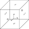
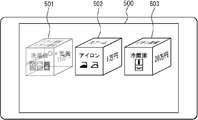
- FIG. 4 is a schematic diagram for explaining the identification information of each surface of the solid object.
- the identification information of each surface may be information that can identify the surface defined by the information to be defined.
- X1 surface “X2” is included in each surface.
- the names “plane”, “Y1 plane”, “Y2 plane”, “Z1 plane”, and “Z2 plane” are given.
- the X1 plane is the right plane as viewed from the front of the three-dimensional object among the planes perpendicular to the x-axis of the three-dimensional object when the three-dimensional object is arranged in the virtual three-dimensional space.
- the X2 plane is assumed to be the right plane when viewed from the front of the three-dimensional object among the planes perpendicular to the x-axis of the three-dimensional object when the three-dimensional object is arranged in the virtual three-dimensional space.
- the Y1 plane is assumed to be the upper plane when viewed from the front of the three-dimensional object among the planes perpendicular to the y-axis of the three-dimensional object when the three-dimensional object is arranged in the virtual three-dimensional space. It is assumed that the Y2 plane is a lower plane as viewed from the front of the three-dimensional object among the planes perpendicular to the y-axis of the three-dimensional object when the three-dimensional object is arranged in the virtual three-dimensional space.
- the Z1 plane is assumed to be a front-side plane as viewed from the front of the three-dimensional object among the planes perpendicular to the z-axis of the three-dimensional object when the three-dimensional object is arranged in the virtual three-dimensional space.
- the Z2 plane is assumed to be a back plane as viewed from the front of the three-dimensional object among the planes perpendicular to the z-axis of the three-dimensional object when the three-dimensional object is arranged in the virtual three-dimensional space.
- each surface here are, for example, coordinates represented using coordinate axes set in the three-dimensional object. For this reason, even if the direction of the three-dimensional object is changed, the information defining each surface does not change. That is, the X1, X2, Y1, Y2, Z1, and Z2 surfaces may be considered as surfaces that are fixed in advance with respect to the three-dimensional object.
- FIG. 5 is a diagram showing an acquisition condition information management table for managing acquisition condition information associated with each surface indicated by the shape information.
- the acquisition condition information management table is created in advance by a user or the like, and is stored in, for example, the shape information storage unit 101 or the like.
- the acquisition condition information management table has items of “X1 plane”, “X2 plane”, “Y1 plane”, “Y2 plane”, “Z1 plane”, and “Z2 plane”. “X1 plane”, “X2 plane”, “Y1 plane”, “Y2 plane”, “Z1 plane”, “Z2 plane” are respectively the X1, X2, Y1, Y2, This is acquisition condition information for designating placement information to be placed on each of the Z1 and Z2 planes.
- the acquisition condition information is information that specifies a tag of the placement information placed on each surface.
- “specification” is acquisition condition information that specifies information for placement to which a specification tag that is normally displayed as “ ⁇ specification>” is added.
- “Product name, color” is acquisition condition information that specifies both the product name tag and the placement information to which the color tag is added.
- “-” Indicates that there is no acquisition condition information.
- the acquisition condition information for the surfaces constituting all the three-dimensional objects is defined by the acquisition condition information of one record.
- the acquisition condition information may be set for each 3D object, 3D object group, or the like. In this case, the 3D object or 3D to which the acquisition condition information is applied to the acquisition condition information record.
- An attribute for designating a group of objects for example, an attribute such as “object ID” described above may be added.
- FIG. 6 is a solid object position information management table for managing the solid object position information stored in the solid object position information storage unit 103.
- the three-dimensional object position information management table has items of “object ID”, “coordinates (x, y, z)”, and “rotation angle (x, y, z)”.
- the “object ID” is identification information for identifying a three-dimensional object, and corresponds to the “object ID” of the shape information described above.
- Coordinats (x, y, z)” is information indicating the coordinates at which the solid object indicated by the “object ID” of the same record is arranged.
- “Rotation angle (x, y, z)” indicates a rotation angle when the x-axis, y-axis, and z-axis of the three-dimensional object are the rotation axes.
- the width direction, the height direction, and the depth direction of the three-dimensional object are respectively the x-axis direction, the y-axis direction, and the z-axis in the virtual three-dimensional space. It shall be arranged parallel to the direction.
- the three-dimensional object position information is the two-dimensional information of the three-dimensional object. It may be information indicating coordinates on the background image or the like for indicating the position where the image is arranged. In this case, the three-dimensional object position information may be two-dimensional coordinate information, for example.
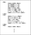
- FIG. 7 is a diagram showing the placement information stored in the placement information storage unit 102.
- the placement information forms data in XML format.
- the arrangement information does not have to be data in XML format, and may be data in a format in which the data can be referred to by item or attribute.
- each arrangement information is assumed to be tagged data, that is, data surrounded by a start tag and an end tag.
- the arrangement information is created and accumulated in advance by a user or the like.
- the placement information is grouped by product.
- a pair of product tags that is, tagged data in a range delimited by “ ⁇ product>” and “ ⁇ / product>” is information for arrangement of one product. If the information for specifying a file or the like, for example, link information is included as the placement information, the information on the file specified thereby is acquired by the image information configuration unit 105 as the placement information.
- FIG. 8 is a diagram showing an area designation information management table for managing area designation information.
- the area designation information management table has items of “object ID”, “surface”, and “synthesis mode change instruction”.
- the “object ID” is identification information for identifying a three-dimensional object, and corresponds to the “object ID” of the shape information described above.
- “Surface” is area designation information, and the area corresponding to this face on the image of the three-dimensional object is an area used for determining whether or not to output a compositing mode change instruction.
- the surface is indicated by the name of the surface of the three-dimensional object as shown in FIG.
- “Combination mode change instruction” is a composition mode change instruction. It is assumed that the area designation information management table is stored in advance in a storage unit such as the shape information storage unit 101, for example. Here, the area designation information is managed for each solid object, but one area designation information management table may be shared by a plurality of solid objects.
- the image information configuration unit 105 of the information processing apparatus 1 first displays the “object ID” shown in FIG. ”Is read as“ OBJ1 ”and temporarily stored in a memory or the like.
- the image information configuration unit 105 arranges the three-dimensional object from which the shape information has been read, that is, the three-dimensional object whose “object ID” is “OBJ1” (hereinafter referred to as the three-dimensional object “OBJ1”).
- the area information is acquired using the acquisition condition information as follows.
- the acquisition condition information of each surface constituting the solid object “OBJ1” is read from the acquisition condition information management table shown in FIG. 7 out of the arrangement information group specified by the value of the “corresponding group” attribute of the solid object “OBJ1” in the shape information management table shown in FIG. 3 among the arrangement information shown in FIG. Then, the placement information that matches the acquisition condition information of each surface is sequentially read out.
- “product name“ washing machine ”” that is the value of the “corresponding group” attribute of the three-dimensional object “OBJ1” is read from the shape information management table of FIG.
- This value means that the arrangement information group corresponding to the three-dimensional object “OBJ1” is a group including arrangement information whose element of the product name tag is “washing machine”.
- “price” which is the acquisition condition information of “X1 plane” in FIG. 5 is read.
- the information (element) to which the “price tag” is attached is read from the arrangement information group including the product name tag whose element is “washing machine” in the arrangement information shown in FIG. .
- the placement information including the product name tag whose element is “washing machine” is the tagged information within the range surrounded by the first product tag in FIG. 7, this product tag From the range surrounded by, the placement information which is text information “150,000 yen” with the price tag attached is read.
- the read information is temporarily stored in a storage medium or the like (not shown) in association with the X1 surface of the three-dimensional object “OBJ1”.
- arrangement information is acquired for other surfaces constituting the three-dimensional object “OBJ1”.
- the text information “washing machine” with the product name tag and the “washing machine red.gif”, “washing machine white.gif”, and “washing machine” tags with the “color” tag are attached.
- Image information “black.gif” is acquired as arrangement information.
- text information “Ox Electric” is acquired.
- the text information of the tag name of the placement information for example, “product name”, “specification”, “color”, “price”, etc. is obtained and the obtained placement information is acquired. You may set so that it may accumulate
- the image information configuration unit 105 determines the 3D object position information corresponding to the 3D object “OBJ1” from the 3D object position information management table shown in FIG. Is read. Specifically, “(100, 300, 100)” that is the value of “coordinate (x, y, z)” of the record whose “object ID” is “OBJ1”, and “rotation angle (x, y, z)”. z) ”(“ 0, 0, 0) ”is read out. Then, the image information configuration unit 105 configures the image information of the three-dimensional object “OBJ1” using the shape information of the three-dimensional object “OBJ1”.
- the position and orientation of the three-dimensional object “OBJ1” are set to be the position and orientation indicated by the object arrangement information read from the object arrangement information management table.
- the placement information acquired by the image information configuration unit 105 using the acquisition condition information specified for each surface is placed on each surface of the three-dimensional object “OBJ1”.
- the coordinate axes are set so that a projection view of the three-dimensional object is configured.
- the image information composing unit 105 reads out information indicating an image mode designated by default from a storage unit or the like (not shown). For example, here, it is assumed that the image mode specified by default indicated by the read information is “a mode in which images before and after are combined with 0% transparency”, that is, a mode in which images are combined so as to be opaque.
- the image information configuration unit 105 renders the shape information by arranging the placement information so that each surface of the three-dimensional object “OBJ1” is opaque.
- the image information configuration unit 105 sets the background to white, and the corresponding placement information To render each side of the 3D object opaque.
- drawing is not performed at all on the image of the back side of the surface of the 3D object that overlaps when viewed from the viewpoint of rendering.
- the X2, Y2, and Z2 planes are located behind the X1, Y1, and Z1 planes. Therefore, the images of these surfaces are not included at all in the generated image. Note that, since it is a well-known technique to determine the front-to-back relationship of surfaces or to perform synthesis using a designated synthesis mode at the time of rendering or the like, detailed description thereof is omitted here.
- the image information of the three-dimensional object is similarly configured for other three-dimensional objects.
- the image information configuration unit 105 further combines the configured images of the three-dimensional object on the background image specified by default or the like to configure image information including the three-dimensional object.
- the output unit 106 outputs the image information synthesized by the image information configuration unit 105.
- the output unit 106 includes a monitor 500 and displays image information of the three-dimensional object on the monitor 500.
- FIG. 9 shows a display example.
- the solid object 501 is a solid object “OBJ1”
- the solid object 502 is a solid object “OBJ2”
- the solid object 503 is a solid object “OBJ3”.
- the coordinate values and the positions of the three-dimensional objects shown in the figure are for explanation, and are not accurately drawn according to the actual size. This is the same in other embodiments.
- each solid object corresponds to a product, and an image for each product color, specifications, price, and the like are displayed on the surface of each solid object. It is possible to easily grasp the correspondence between the product and the specification information related to the product.
- the user touches the surface on which the product name is displayed on the image of the three-dimensional object 501 that is the three-dimensional object “OBJ1” displayed on the monitor 500 with a finger or the like.
- the screen of the information processing apparatus 1 is provided with a transparent touch panel, and coordinate information corresponding to the touched position is input to the position designation information receiving unit 1041 from the touch panel.
- the position designation information receiving unit 1041 receives position designation information corresponding to the position touched by the user. For example, assume that the coordinate information received here is (Xa, Ya).
- the combination mode acquisition unit 1042 indicates that the coordinate information of the position touched by the user indicated by the position specification information received by the position specification information receiving unit 1041 is the area specification information managed by the area specification information management table shown in FIG. It is determined whether or not it is located on any one of the designated areas.
- FIG. 11 is a diagram schematically showing the area indicated by the area designation information managed by the area designation information management table shown in FIG. 8 superimposed on the image output by the output unit 106.
- the hatched portion is the area indicated by the area designation information.
- the area 81 is an area corresponding to the surface “Z1 surface” of the solid object having the object ID “OBJ01”.
- the area 82 is an area corresponding to the surface “X1 surface” of the solid object having the object ID “OBJ02”.
- the region 83 is a region corresponding to the surface “X1 surface” of the solid object having the object ID “OBJ1”.
- the synthesis mode acquisition unit 1042 acquires the coordinate information indicating the “surface” shown in FIG. 8 in the rendered image, that is, the coordinate information indicating the region corresponding to the region designation information, from the rendering result of the image information configuration unit 105, for example. .
- This coordinate information may be the coordinate information of all the pixels constituting the area corresponding to the “surface”, or the coordinate information of the outline of the area corresponding to the “surface”.
- the image information configuration unit 105 manages, for example, each area and information on a set of “face” and “object ID” corresponding to each area in association with each other.
- the synthesis mode acquisition unit 1042 selects one of the one or more areas indicated by the area designation information as the position indicated by the coordinate information (Xa, Ya) that is the position designation information received by the position designation information reception unit 1041. It is determined whether it is one on the area.
- the compositing mode acquisition unit 1042 determines that the coordinate information (Xa, Ya) is the position on the area 81 specified by the area specifying information corresponding to the solid object whose object ID is “OBJ1”, that is, the object ID. Is determined to be a position on the area 81 corresponding to the surface “Y1 surface” of the solid object having “OBJ01”.
- the synthesis mode acquisition unit 1042 determines whether or not the position indicated by the position designation information received immediately before is a position on the same area 81.
- position designation information since position designation information has not been received before, it is determined that a position on the same area 81 has not been designated. If a position on the same area 81 is designated, it is preferable not to perform a process for outputting a synthesis mode change instruction as will be described later. This is to prevent the composite mode change instruction from being repeatedly acquired.
- the synthesis mode acquisition unit 1042 acquires the “synthesis mode” and “object ID” corresponding to the area designation information corresponding to the area 81 from the area designation information management table shown in FIG. Specifically, in the area designation information management table shown in FIG. 8, a record corresponding to the arrangement area 81, that is, a record whose object ID is “OBJ01” and “face” is “Z1 face” is detected. A set of a value of “synthesis mode” and a value of “object ID” included in the record is acquired. Here, “transparency 50%” is acquired as the value of “synthesis mode”, and “OBJ01” is acquired as the value of “object ID”.
- the composition mode acquisition unit 1042 finally changes from the acquired information “the composition mode when compositing the three-dimensional object with the object ID“ OBJ01 ”to the composition mode that transmits with a transparency of 50%.
- An image mode change instruction for instructing “to do” is acquired.
- the instruction acquired here may actually be considered as a command or the like.
- This process may be considered as a process of resetting the synthesis mode of other solid objects except the object ID “OBJ01” to the default synthesis mode. As a result, the image of the three-dimensional object that was displayed immediately before the composition mode was changed is displayed in the default composition mode.
- the image information configuration unit 105 configures the image information of the three-dimensional object using the shape information, the placement information, the three-dimensional object position information, and the like, as described above.
- an image mode change instruction for instructing to “change the composition mode when compositing the solid object having the object ID“ OBJ01 ”to a composition mode that transmits with a transparency of 50%” is acquired. Since the means 1042 has acquired, for the object whose object ID is “OBJ01”, in accordance with this image mode change instruction, the image mode is changed to “synthesizing mode in which the transparency is set to 50%” and the image is configured. To do.
- the image information configuration unit 105 renders the shape information by arranging the placement information so that the transparency of each surface of the solid object “OBJ1” is 50%.
- the background color of each surface of the three-dimensional object indicated by the shape information is set to, for example, white by default
- the image information configuration unit 105 sets the background to white, and the corresponding placement information To render all surfaces of the solid object so that the transparency is 50%.
- the image of the back side of the surface of the 3D object that is overlapped when viewed from the viewpoint of rendering is drawn so that a part of the surface arranged on the front side can be seen through. Is done.
- each surface is made opaque as described above.
- Image information a description is given of a case where the information arranged on the X2 plane and the Z2 plane is arranged so as to be easy to see when viewed from the viewpoint of rendering.
- information arranged on the X2 plane or the Z2 plane is obtained by inverting the information shown in FIG. Arranged in the direction.
- FIG. 12 shows an output example of the image information configured as described above. As shown in FIG. 12, for a three-dimensional object touched with a finger, an image on the back side of the three-dimensional object that could not be seen by opaque composition can be viewed from the front side.
- the compositing mode is changed depending on whether or not the position indicated by the position specifying information exists on the area indicated by the area specifying information.
- the image of the three-dimensional object is changed.
- An example in which the composition mode is changed according to the distance from the position indicated by the position designation information will be described. As shown in FIG. 9, the process is the same as that in the above specific example until the solid object is displayed.
- the position designation information receiving means 1041 acquires coordinate information of the touched position.
- the synthesis mode acquisition unit 1042 calculates coordinates indicating the position of each solid object (for example, the center position of each solid object), and the distance between the coordinates indicating the position of each solid object and the coordinates indicated by the position designation information Are calculated for each solid object. Then, a synthesis mode change instruction for changing the synthesis mode of each three-dimensional object to the transmission mode with the reciprocal of the calculated distance as the transparency is acquired. By using the reciprocal of the distance, the transparency of the three-dimensional object displayed at a position away from the touched position is set to be low.
- the image information configuration unit 105 configures the image information of the 3D object created by combining in accordance with the combining mode change instruction acquired for each 3D object.
- FIG. 14 shows an output example of the image information configured as described above.
- the transparency of the solid object 501 close to the touched position is high
- the transparency of the solid object 503 farthest from the touched position is the lowest
- the distance from the touched position is an intermediate transparency between the three-dimensional object 501 and the three-dimensional object 503.
- the transparency of the three-dimensional object can be changed continuously or in multiple stages according to the position on the image designated by the user with a finger or the like and the distance to each three-dimensional object. it can. Accordingly, it is possible to interactively and intuitively change the transparency of the three-dimensional object to be transmitted at a position designated by the user. Needless to say, instead of the reciprocal of the distance, another arithmetic expression using the distance as a variable may be used in accordance with the application.
- the position designation information indicates The transparency may be lowered when the position is on the solid object or close to the solid object.
- the present embodiment it is possible to appropriately display a solid object by changing the composition mode of the surface of the solid object in accordance with the compositing mode change instruction. For this reason, for example, by switching the composition mode, it is possible to make the arrangement information arranged on the back surface of the three-dimensional object visible or not visible from the front side.
- the compositing mode can be changed interactively.
- the position indicated by the position designation information is on the solid object or when the composition mode is changed when the position is close to the solid object, for example, when the solid object is operable, Since the synthesis mode of the solid object to be operated can be changed, the trouble of switching the synthesis mode becomes unnecessary, and the operability is improved.
- the information processing apparatus 1 can be used as a new user interface model, a new file system, and a new window system that can output information that can be defined in many ways.
- a solid object image or the like output by the information processing apparatus 1 may be used as an input interface image or the like for receiving an instruction or the like for performing other processing.
- the image information configuration unit 105 or a processing unit (not shown) is used.
- the shape information corresponding to the placement information received by the receiving unit (not shown) that receives the placement information stored in the placement information storage unit 102 or the placement information stored in the placement information storage unit 102 May be acquired by generation or reading, and image information for output may be configured using the acquired shape information.
- an image information configuration unit or a processing unit (not shown) acquires information on the number of pieces of surface information to be placed on the three-dimensional object from the placement information received by a receiving unit (not shown) that receives the placement information.
- n is an integer greater than or equal to 2
- the value of n may be used to automatically generate shape information of an n-hedron, for example, a regular n-hedron.
- template information or the like of n-face shape information prepared in advance may be read.
- An algorithm or the like constituting such a regular n-hedron may be stored in advance in a storage medium (not shown) and read out when necessary. This also applies to other embodiments.
- each process may be realized by centralized processing by a single device (system), or by distributed processing by a plurality of devices. May be.
- two or more communication means such as an information transmission unit
- two or more communication means existing in one apparatus may be physically realized by one medium.
- information related to processing executed by each component for example, information received, acquired, selected, generated, transmitted, and received by each component.
- information such as threshold values, mathematical formulas, addresses, etc. used by each component in processing is retained temporarily or over a long period of time on a recording medium (not shown) even when not explicitly stated in the above description. It may be.
- the storage of information in the recording medium (not shown) may be performed by each component or a storage unit (not shown).
- reading of information from the recording medium (not shown) may be performed by each component or a reading unit (not shown).
- the information processing apparatus may be a stand-alone apparatus or a server apparatus in a server / client system.
- the output unit or the reception unit receives an input or outputs a screen via a communication line.
- each component may be configured by dedicated hardware, or a component that can be realized by software may be realized by executing a program.
- each component can be realized by a program execution unit such as a CPU reading and executing a software program recorded on a recording medium such as a hard disk or a semiconductor memory.
- the software that realizes the information processing apparatus in each of the above embodiments is a program as described below. That is, the program includes a synthesis mode change instruction acquisition unit that acquires a synthesis mode change instruction that is an instruction to change a synthesis mode for at least the front and back surfaces of the surfaces constituting the solid object.
- Shape information that is information for designating the shape of a three-dimensional object that is a three-dimensional object stored in the shape information storage unit and one or more surfaces that constitute the three-dimensional object stored in the arrangement information storage unit
- Information for placement that is one or more pieces of information that can be placed on one or more faces of the three-dimensional object, and corresponding to each of the one or more faces of the read three-dimensional object Image information in which the placement information is arranged, and at least an image of a surface that overlaps the front and rear is changed in the synthesis mode
- an image information forming unit constituting the synthesized image information in accordance with the synthesis mode shows instructs to change a program for the image information configuration unit is to function as an output unit for outputting the image information constructed.
- the functions realized by the program do not include functions that can only be realized by hardware.
- functions that can be realized only by hardware such as a modem and an interface card in an acquisition unit that acquires information, an output unit that outputs information, and the like are not included in the functions realized by the program.
- the computer that executes this program may be singular or plural. That is, centralized processing may be performed, or distributed processing may be performed.
- FIG. 15 is a schematic diagram showing an example of an external appearance of a computer that executes the program and realizes the information processing apparatus according to the embodiment.
- the above-described embodiment can be realized by computer hardware and a computer program executed on the computer hardware.
- a computer system 900 includes a computer 901 including a CD-ROM (Compact Read Only Memory) drive 905 and an FD (Floppy (registered trademark) Disk) drive 906, a keyboard 902, a mouse 903, a monitor 904, and the like. Is provided.
- a computer 901 including a CD-ROM (Compact Read Only Memory) drive 905 and an FD (Floppy (registered trademark) Disk) drive 906, a keyboard 902, a mouse 903, a monitor 904, and the like.
- FIG. 16 is a diagram showing an internal configuration of the computer system 900.
- a computer 901 in addition to the CD-ROM drive 905 and the FD drive 906, a computer 901 is connected to an MPU (Micro Processing Unit) 911, a ROM 912 for storing a program such as a bootup program, and the MPU 911.
- MPU Micro Processing Unit
- ROM Read Only Memory
- a RAM Random Access Memory
- a hard disk 914 that stores application programs, system programs, and data
- an MPU 911 and a ROM 912 are interconnected.
- a bus 915 The computer 901 may include a network card (not shown) that provides connection to the LAN.
- a program that causes the computer system 900 to execute the functions of the information processing apparatus according to the above-described embodiment is stored in the CD-ROM 921 or the FD 922, inserted into the CD-ROM drive 905 or the FD drive 906, and transferred to the hard disk 914. May be. Instead, the program may be transmitted to the computer 901 via a network (not shown) and stored in the hard disk 914. The program is loaded into the RAM 913 when executed. The program may be loaded directly from the CD-ROM 921, the FD 922, or the network.
- the program does not necessarily include an operating system (OS) or a third-party program that causes the computer 901 to execute the functions of the information processing apparatus according to the above embodiment.
- the program may include only a part of an instruction that calls an appropriate function (module) in a controlled manner and obtains a desired result. How the computer system 900 operates is well known and will not be described in detail.
- the information processing apparatus is suitable as an apparatus for outputting information, and is particularly useful as an apparatus for arranging and outputting information on a three-dimensional object.
Landscapes
- Engineering & Computer Science (AREA)
- General Engineering & Computer Science (AREA)
- Theoretical Computer Science (AREA)
- Human Computer Interaction (AREA)
- Physics & Mathematics (AREA)
- General Physics & Mathematics (AREA)
- User Interface Of Digital Computer (AREA)
- Image Generation (AREA)
- Processing Or Creating Images (AREA)
Abstract
【課題】従来の情報処理装置においては、立体オブジェクトを適切に表示させることができないという課題があった。 【解決手段】立体オブジェクトの形状情報が格納され得る形状情報格納部101と、立体オブジェクトの面に配置される配置用情報が格納され得る配置用情報格納部102と、立体オブジェクトの面のうちの、少なくとも前後に重なりあう面に対する合成モード変更指示を取得する合成モード変更指示取得部104と、立体オブジェクトの形状情報と当該立体オブジェクトの面に配置される配置用情報とを読み出し、立体オブジェクトの面に、それぞれに対応した配置用情報を配置した画像情報であって、前後に重なりあう面の画像を、合成モード変更指示が指示する合成モードに応じて合成した画像情報を構成する画像情報構成部105と、構成された画像情報を出力する出力部106とを備えた。
Description
本発明は、立体的な画像等を表示する情報処理装置等に関するものである。
従来の技術として、立体図形の各領域にメニュー項目が割り当てられた、前記立体図形を表示する表示工程と、前記立体図形を、入力する指示コマンドに従って、移動させる移動工程と、前記立体図形に割り当てられたメニュー項目から、所要のメニューを選択する選択工程と、選択されたメニューに対応した処理を実行する選択処理実行工程とを、備えることを特徴とする3次元メニュー選択方法が知られていた(例えば、特許文献1参照)。
しかしながら、従来の情報処理装置等においては、通常は、立体オブジェクトの背面は、立体オブジェクトの前面部分に重なって前面に隠れてしまう。このため、立体オブジェクトの背面を表示させることができないという課題があった。このため、立体オブジェクトの背面の画像を見るためには、立体オブジェクトを回転させたりする必要があり、手間と時間がかかり、利便性がわるい、という課題があった。
一方で、立体オブジェクトの各面を透過させて表示させるようにすれば、立体オブジェクトの背面にどのような情報が配置されているか等を、立体オブジェクトの操作を行うことなく視覚的に認識することが可能である。しかしながら、この場合、背面の画像が、前面の画像と合成されて表示されることとなるため、前面の情報が把握しにくくなってしまうという課題があった。例えば、背面の画像を見る必要がない場合においては、背面の画像は、単に前面の画像の視認性を妨げる画像となってしまう。
このように、従来の技術においては、立体オブジェクトを適切に表示させることができない、という課題があった。
本発明の情報処理装置は、立体のオブジェクトである立体オブジェクトの形状を指定する情報である形状情報が格納され得る形状情報格納部と、前記立体オブジェクトを構成する1以上の面に配置される1以上の情報である配置用情報が格納され得る配置用情報格納部と、前記立体オブジェクトを構成する面のうちの、少なくとも前後に重なりあう面に対する合成モードを変更する指示である合成モード変更指示を取得する合成モード変更指示取得部と、前記立体オブジェクトの形状情報と、当該立体オブジェクトの1以上の面に配置される前記配置用情報とを読み出し、当該読み出した立体オブジェクトの1以上の面に対し、それぞれに対応した前記配置用情報を配置した画像情報であって、少なくとも前後に重なりあう面の画像を前記合成モード変更指示が変更を指示する合成モードに応じて合成した画像情報を構成する画像情報構成部と、前記画像情報構成部が構成した画像情報を出力する出力部とを備えた情報処理装置である。
かかる構成により、立体オブジェクトを構成する面の合成モードを切り替えて、立体オブジェクトを適切に表示させることができる。これにより、例えば、合成モードの切換によって、立体オブジェクトの背面等に配置されている配置用情報を前面側から視認できるようにしたり視認できないようにしたり切り替えることができ、状況に応じて立体オブジェクトの視認性を向上させることができる。
また、本発明の情報処理装置は、前記情報処理装置において、前記合成モード変更指示は、透過度を変更する指示であり、前記画像情報構成部は、前記立体オブジェクトを構成する面のうちの、少なくとも前後に重なりあう面の少なくとも前方に配置される面の透過度を変更した画像情報を構成する情報処理装置である。
かかる構成により、立体オブジェクトを構成する面の透過度についての合成モードを切り替えて、立体オブジェクトを適切に表示させることができる。これにより、例えば、透過度についての合成モードの切換によって、立体オブジェクトの前方の面を適宜透過させることが可能となり、立体オブジェクトの背面等に配置されている配置用情報を前面側から視認できるようにしたり視認できないようにしたり切り替えることができ、状況に応じて立体オブジェクトの視認性を向上させることができる。
また、本発明の情報処理装置は、前記情報処理装置において、前記合成モード変更指示受付部は、前記画像情報が示す画像の位置を指定する情報である位置指定情報を受け付ける位置指定情報受付手段と、前記位置指定情報が指定する位置と、前記画像情報における立体オブジェクトの位置との位置関係に応じて、当該立体オブジェクトに対する合成モード変更指示を取得する合成モード取得手段と、を備えた情報処理装置である。
かかる構成により、立体オブジェクトを構成する面の合成モードを、位置指定情報が示す位置に応じて切り替えて、立体オブジェクトを適切に表示させることができる。これにより、例えば、ユーザが示す位置等に応じた位置指定情報に応じた最適な合成モードで立体オブジェクトを表示させることが可能となる。
また、本発明の情報処理装置は、前記情報処理装置において、前記合成モード取得手段は、前記位置関係に応じて二以上の異なる合成モードのいずれかを指定する合成モード変更指示を取得する情報処理装置である。
かかる構成により、合成モードを切り替えて表示させることができる。
また、本発明の情報処理装置は、前記情報処理装置において、前記合成モード取得手段は、前記位置指定情報が指定する位置が、前記立体オブジェクト上の所定の領域内の位置であるか否かを検出し、当該検出結果に応じて、当該立体オブジェクトに対する合成モード変更指示を取得する情報処理装置である。
かかる構成により、位置指定情報が示す位置が、立体オブジェクトの所定の領域上であるか否かによって、立体オブジェクトを構成する面の合成モードを切り替えて表示させることが可能となり、立体オブジェクトを適切に表示させることができる。これにより、例えば、合成モードを立体オブジェクトのどのような位置が指定された場合に変更するかをユーザ等が適宜指定することが可能となる。
本発明による情報処理装置等によれば、立体オブジェクトを構成する面の合成モードを切り替えて、立体オブジェクトを適切に表示させることができる。
以下、情報処理装置等の実施形態について図面を参照して説明する。なお、実施の形態において同じ符号を付した構成要素は同様の動作を行うので、再度の説明を省略する場合がある。
(実施の形態)
図1は、本実施の形態における情報処理装置1のブロック図である。
図1は、本実施の形態における情報処理装置1のブロック図である。
情報処理装置1は、形状情報格納部101、配置用情報格納部102、立体オブジェクト位置情報格納部103、合成モード変更指示取得部104、画像情報構成部105、および出力部106を備えている。合成モード変更指示取得部104は、位置指定情報受付手段1041及び合成モード取得手段1042を備えている。
本実施の形態にかかる情報処理装置1は、例えば、コンピュータや、携帯電話や、PDA(携帯情報端末)、携帯電話と情報端末とを組み合わせた高機能携帯電話、携帯型デジタル音楽プレーヤ、テレビ等の表示デバイスを有するオーディオビジュアル機器等の情報機器である。かかることは他の実施の形態においても同様である。
形状情報格納部101には、立体のオブジェクトである立体オブジェクトの形状を指定する情報である形状情報が格納され得る。形状情報とは、具体的には、仮想三次元空間内に配置されるオブジェクトの形状等を定義する情報である。形状情報は、例えば、立体オブジェクトのいわゆるモデリング情報である。ここで述べる立体オブジェクトは、例えば3Dオブジェクトや3Dモデルや立体モデルと呼ばれるものも含む。形状情報は、立体オブジェクトの頂点の座標の情報や、境界線や面等を表現する方程式のパラメータの情報等である。立体オブジェクトは、通常、面を定義する情報、あるいは面を定義可能な情報を有しており、1以上の面により構成されている。立体オブジェクトは、例えば、面の構成方法によって、ポリゴンモデリングや、自由曲面を利用したモデリング等に分類できる。形状情報には、立体オブジェクトを出力する際の、立体オブジェクトの色や、透明度、反射、屈折率、バンプなどの設定項目の情報を含んでも良い。形状情報格納部101には、1以上の立体オブジェクトの形状情報が格納され得る。立体オブジェクトの形状は、球、円柱、六面体や八面対等の多面体や、立方体、円錐、角錐等、どのような形状であっても良い。形状情報のサイズ等の単位等は、絶対的な単位であっても、相対的な単位であっても良い。また、複数の立体オブジェクトにおいて、共用可能な形状情報等は、リンク情報等を用いて参照することで、相互利用できるようにしても良い。形状情報格納部101は、不揮発性の記録媒体が好適であるが、揮発性の記録媒体でも実現可能である。
配置用情報格納部102は、立体オブジェクトを構成する面に配置可能な1以上の情報である配置用情報が格納され得る。配置用情報は、立体オブジェクトを構成する面に配置して出力、例えば表示可能な情報であれば、静止画や動画等の画像情報や、テキスト情報等、どのような情報であっても良い。また、ここで述べる配置とは、いわゆる立体オブジェクトの面に対する画像情報等のマッピングと考えても良い。また、配置用情報は、マッピング対象となる情報、例えばテクスチャ情報と考えても良い。配置用情報のデータ構造は問わない。例えば配置用情報は、タグ付けされた情報であっても良い。また、配置用情報は、テーブルや、データベースにより、例えば属性等と対応付けて管理された情報でも良い。また、配置用情報は、予めグループ化されていても良い。
配置用情報と、当該配置用情報が配置される立体オブジェクトの面とはどのように対応付けられていても良い。例えば、配置用情報またはその識別情報と、当該配置用情報に対応付けられた立体オブジェクトの面またはその識別情報との組を、一のレコードの複数の項目として管理する管理情報等を用いて管理されても良い。この管理情報は、例えば図示しない格納部等に格納しておくようにすればよい。また、形状情報格納部101と配置用情報格納部102とが一の格納部により構成されており、形状情報が示す立体オブジェクトの面を示す情報と当該面に配置される配置用情報とが対応付けられて格納されていても良い。また、形状情報が示す立体オブジェクトの面に対して、当該面に配置される配置用情報を取得するための条件を示す情報である取得条件情報等が対応付けられて、形状情報格納部101等に格納されていても良い。取得条件情報は、例えば、面に配置される配置用情報を検索するための検索式等の検索条件を示す情報である。この場合、各面に対応付けられた検索式等の情報を用いて検索を行うことで、面に配置される配置用情報を取得することが可能となる。
なお、情報取得条件情報は、1以上の立体オブジェクトの面に配置される1以上の配置用情報を結果的に指定可能な情報であれば、どのような情報であっても良い。例えば、取得条件情報は、配置用情報が項目分けされている場合、その項目を指定する情報であってもよい。また、配置用情報が属性を有している場合、その属性を指定する情報であっても良い。また、配置用情報がタグ付けされている場合、タグ名を指定する情報であっても良い。また、配置用情報にインデックス情報が付与されている場合、このインデックスを指定する情報であっても良い。また、配置用情報の場所やファイル名やディレクトリ等を指定する情報であっても良い。また、配置用情報を検索するための検索式や演算式であっても良い。なお、検索式は、必ずしも式の形で示されている必要はなく、検索に利用可能なキーワード等であっても良い。例えば、この検索式で示される取得条件情報は、「select」、「from」、「where」等の組み合わせ等である。なお、「select」は取得する配置用情報の項目、「from」は検索対象となる複数の配置用情報を指定する情報、「where」は検索のための条件を示す情報である(SQLの仕様を参照)。また、演算式で示される取得条件情報とは、例えば、1以上の配置用情報に対して行われる演算式であり、例えば、数値で表される2つの配置用情報を指定する情報と、これらの平均を算出する演算式等で表されたものや、現在の時間等に所定時間を加減算する演算式等で表されたもの等である。取得条件情報とは、出力対象となりうる全ての立体オブジェクトにそれぞれ個別に指定されていてもよいし、全ての立体オブジェクト共通に指定されていても良い。また、一部の立体オブジェクトに共通に指定されていても良い。また、立体オブジェクトに属性等が設定されている場合、この属性が一致する立体オブジェクトに共通の取得条件を指定しても良い。また、取得条件情報は、立体オブジェクトの各面に対して予め指定されていてもよいし、各面にランダムに指定されても良い。配置用情報格納部102は、不揮発性の記録媒体が好適であるが、揮発性の記録媒体でも実現可能である。
立体オブジェクト位置情報格納部103には、立体オブジェクトの位置を指定する情報である立体オブジェクト位置情報が格納され得る。ここで述べる位置とは、例えば、仮想三次元空間内における位置である。但し、立体オブジェクトをレンダリングした二次元画像を二次元の背景画像上に配置する場合等においては、立体オブジェクト位置情報は二次元平面上における位置情報であっても良い。立体オブジェクト位置情報は、例えば、立体オブジェクトの位置に加えて、立体オブジェクトの配置される方向、即ちオブジェクトの向きや立体オブジェクトの大きさ等を示す情報等を有していても良い。立体オブジェクトの位置とは、例えば、立体オブジェクト内の1以上の部分の仮想三次元空間内等における位置と考えても良い。例えば、立体オブジェクト位置は、立体オブジェクトを構成する辺等が集まる1以上の頂点や辺や面の位置であっても良いし、立体オブジェクトの中心や重心等の位置であっても良い。立体オブジェクト位置情報は、立体オブジェクトの位置を結果的に指定可能な情報であればよい。立体オブジェクト位置情報は、例えば、立体オブジェクトが配置される位置の座標を指定する情報である。立体オブジェクトの位置は、例えば、座標等で表される。立体オブジェクトの位置を指定する座標は、仮想三次元空間内等に設定された絶対的な座標であっても良いし、他の立体オブジェクト等に対して設定された相対的な座標であっても良い。例えば、立体オブジェクトの位置を指定する座標は、立体オブジェクトを構成する辺等が集まる頂点の座標であっても良いし、立体オブジェクトの中心や重心等の位置の座標であっても良い。なお、ここでは1以上の立体オブジェクトのそれぞれについて、立体オブジェクト位置情報と立体オブジェクトの形状情報とをそれぞれ設けた場合について説明するが、立体オブジェクト位置情報を形状情報内に含めるようにしても良い。例えば、形状情報の頂点の情報を、例えば、絶対座標とすることで、形状情報を立体オブジェクト位置情報として用いて、立体オブジェクトの位置も指定可能となる。この場合、形状情報格納部101と立体オブジェクト位置情報格納部103とを一の格納部により構成するようにしても良い。後述する画像情報構成部105は、例えば、この立体オブジェクト位置情報を読み出して、この立体オブジェクト位置情報が示す仮想三次元空間内の位置に立体オブジェクトを位置した画像情報を構成する。立体オブジェクト位置情報格納部103は、不揮発性の記録媒体が好適であるが、揮発性の記録媒体でも実現可能である。
合成モード変更指示取得部104は、立体オブジェクトを構成する面のうちの、少なくとも前後に重なりあう面に対する合成モードを変更する指示である合成モード変更指示を取得する。合成モード変更指示は、デフォルトで指定されている合成モードや、現在の合成モードに対して、合成モードを変更する指示を示す情報と考えても良い。合成モード変更指示は、結果的に、変更後の合成モードを、変更前の合成モードとは異なる合成モードに変更させる指示であればよく、変更後の合成モードを明示的に指定する情報を含んでいても良いし、含まなくても良い。変更後の合成モードを明示的に指定する情報を含む場合の合成モード変更指示取得部104が取得する合成モード変更指示は、例えば、合成モードを90%の透過度で透過させるモードに変更する指示等の、変更後の特定の合成モードを示す情報を含む情報である。変更後の合成モードを明示的に指定する情報を含まない場合の合成モード変更指示取得部104が取得する合成モード変更指示は、例えば、現在の合成モードとは異なる合成モードに変更する指示等や、予め用意されている二以上の合成モード変更指示を切り替える指示等の、変更後の合成モードを示す情報を含まない情報である。また、変更前とは異なる合成モードを示す情報を、合成モード変更指示と考えても良い。
立体オブジェクトの合成モードとは、例えば、前後に重なった面をどのように合成するかを示す合成方法である。つまり、前面に配置される画像を、当該画像の背面に配置される画像に対してどのように合成するかを示す面の合成方法である。例えば、重なりあう面に配置される画像の画素同士の値を用いて、合成モードにより指定される所定の演算を行うことで得られた画素が、合成された画素である。合成モードとは、例えば、描画モードとも呼ばれる。合成モードは、例えば、所定の透過度で画像を透過させて合成するモードである。この場合の、合成モード変更指示は、透過度を変更する指示と考えても良い。この合成モード変更指示は、透過度を指定する情報を有していても良いし、有していなくても良い。有していない場合、予め設定された透過度で画像を透過させる合成モードを指定する情報と考えて良い。透過度は0~100%等の透過度を示す値であっても良いし、「透明」、「半透明」等の、透過度を示す値と対応付けられた定性的なデータであっても良い。なお、透過度が0%の場合、即ち透過させない場合や、透過度が100%の場合、即ち対象の画像を表示しない場合を、透過させるモードと考えても良いし、異なるモードと考えても良い。また、他の合成モードとしては、例えば、乗算、オーバーレイ、ディザ合成等のモードが知られている。異なる合成モードにおいては、それぞれ、合成する際の演算式やパラメータ等が異なる。また、透過モードと、他の合成モードとを組み合わせたものも合成モードの一つと考えて良い。合成モードやその合成モードに応じて画像を合成する処理等については、3Dソフトウェアや画像処理ソフトウェア等において公知の技術であるので、ここでは説明を省略する。なお、合成モード変更指示が指示する合成モードは、本願においては、結果的に背面の画像の全体または一部をユーザ等が前面から認識可能となるよう透過させることが可能な合成モードであることが好ましい。なお、立体オブジェクトの合成モードは、結果的には、前面に配置される画像を、当該画像の背面に配置される画像に対してどのように表示するかを示す方法や、前面に配置される画像と、当該画像の背面に配置される画像とを重ね合わせて表示する場合の表示方法等、であると考え得るものであることから、立体オブジェクトの表示モードと考えても良い。
なお、ここで述べる前面とは、具体的には、立体オブジェクトを構成する面のうちの、仮想三次元空間を予め指定されている仮想の視点から見た場合に、前方、即ち視点側に位置する面である。なお、ここでの視点とは、例えばレンダリング等を行う際の視点である。また、背面とは、この前面の背後に位置する面である。なお、立体オブジェクトの画像が表示される画面の表面に近い側を前面と考えても良い。なお、ここでは、特に、前面に少なくとも一部が重なっている面だけを背面と考えても良い。あるいは重なっている領域だけを背面と考えても良い。例えば、一の面が湾曲して重なりあっている場合、重なりあった前方の部分を前面、重なりあった後方の部分を背面と考えて良い。
合成モード変更指示は、異なる立体オブジェクトにおいて重なりあう面の合成モードを変更する指示であっても良い。また、合成モード変更指示は、立体オブジェクトを構成する各面の、立体オブジェクトが配置される領域の背景の画像に対する合成モードを変更する指示を含むと考えても良い。例えば、仮想三次元空間に第一の面と第二の面とが配置されていた場合において、立体オブジェクトの合成モードを、50%の透過度で画像を透過させる合成モードに変更する指示を合成モード変更指示を受け付けた場合、第一の面と第二の面との透過度をそれぞれ50%に設定して、背景が透過して見えるようにしてもよい。あるいは、第一の面と第二の面のうちの前面に配置されている面の透過度だけを50%に変更して、背面に配置されている面については、背景が透過して見えないようにしてもよい。
合成モード変更指示は、合成モードの変更対象となる立体オブジェクトを指定する情報や、合成モードの変更対象となる立体オブジェクトの面を指定する情報を含んでも良いし、含まなくてもよい。立体オブジェクトや面を指定する情報が含まれない場合、予め指定された1以上の立体オブジェクトや予め指定された面の合成モードを、後述する画像情報構成部105が画像を構成する際に変更するようにすればよい。また、内部に他の立体オブジェクトを含む立体オブジェクト、即ち入れ子構造となっている立体オブジェクトについての合成モード変更指示は、外側の立体オブジェクトについての合成モードを変更する情報と考えても良いし、外側および内部に位置する立体オブジェクトの両者についての合成モードを変更する情報と考えても良い。
合成モード変更指示取得部104は、例えば、異なる二以上の合成モード間で、合成モードを変更するための合成モード変更指示を取得する。本実施の形態において、合成モードが異なるということは、ここでは、合成モード自身が異なることであっても良いし、一の合成モードにおいて、パラメータ等が異なることであっても良い。例えば、合成モードとして、乗算モードと、オーバーレイモードとを異なる合成モードと考えても良いし、一の合成モードにおける合成に利用されるパラメータの値等が異なるものを、異なる合成モードと考えても良い。例えば、透過度0%で画像を透過させるモードと、および透過度50%で画像を透過させるモードとの組のような、異なる透過度で画像を透過させるモードを、異なる合成モードと考えても良い。なお、この場合の透過度等は,適宜、合成した画像が見やすい値等に設定すればよい。
合成モード変更指示取得部104がどのように合成モード変更指示を取得するかは問わない。例えば、合成モード変更指示取得部104は、マウスや、キーボードや、タッチパッド等の入力デバイス等を用いて、合成モードを切り替えるためのボタンや入力メニュー等の入力インターフェースを操作して入力された合成モード変更指示を受け付けることを取得と考えても良い。また、合成モード変更指示取得部104は、立体オブジェクトの表示される位置と、ユーザが指定する表示画像上の位置との関係に対応した合成モード変更指示を取得してもよい。
なお、受け付けとは、キーボードやマウス、タッチパネルなどの入力デバイスから入力された情報の受け付け、有線もしくは無線の通信回線を介して送信された情報の受信、光ディスクや磁気ディスク、半導体メモリなどの記録媒体から読み出された情報の受け付けなどを含む概念である。入力手段は、テンキーやキーボードやマウスやメニュー画面によるもの等、何でも良い。入力デバイス等から合成モード変更指示を受け付ける場合、合成モード変更指示取得部104は、テンキーやキーボード等の入力手段のデバイスドライバーや、メニュー画面の制御ソフトウェア等で実現され得る。
なお、この実施の形態においては、合成モード変更指示取得部104が、位置指定情報受付手段1041と合成モード取得手段1042とを備えており、これらを用いて、合成モード変更指示を取得する場合を例に挙げて説明する。なお、この場合、合成モード取得手段1042が取得した合成モード変更指示が、合成モード変更指示取得部104が取得した合成モード変更指示と考えて良い。
位置指定情報受付手段1041は、画像情報が示す画像上の位置を指定する情報である位置指定情報を受け付ける。例えば、位置指定情報受付手段1041は、ユーザ等により、マウスやキーボードやタッチパネル等の入力手段等を用いて指定された、後述する出力部106が出力した画像情報が示す画像上の位置を指定する位置指定情報を受け付ける。画像上の位置を指定する情報とは、例えば、ポインタやカーソル等が存在する位置を指定する情報である。また、タッチパネル等において、指で触れている位置を指定する情報である。位置を指定する情報は、例えば表示画面や、表示される画像情報に対応した座標情報である。なお、位置指定情報受付手段1041が受け付ける座標情報は、ポインタやカーソルの位置の情報等から算出される仮想三次元空間内における座標情報であっても良い。位置指定情報受付手段1041は、例えば、ポインタやカーソルや指の位置が存在する位置についての位置指定情報を、所定の時間間隔等の所定のタイミングで受付てもよいし、ポインタやカーソル等が存在する位置において、例えばマウスボタン等のクリックや、Enterキー等の所定のキーの押下や、指によるタッチパネル等のタップ等の所定の動作等が行われた場合に、位置指定情報を受け付けても良い。位置指定情報の入力手段は、テンキーやキーボードやマウスやメニュー画面によるもの等、何でも良い。位置指定情報受付手段1041は、テンキーやキーボードやタッチパネル等の入力手段のデバイスドライバーや、メニュー画面の制御ソフトウェア等で実現され得る。
合成モード取得手段1042は、位置指定情報が指定する位置と、画像情報における立体オブジェクトの位置との位置関係に応じて、当該立体オブジェクトに対する合成モード変更指示を取得する。ここで述べる合成モード変更指示の取得とは、例えば、合成モード変更指示の読み出しや、合成モード変更指示の生成等である。ここで取得する合成モード変更指示は、例えば、合成モード変更指示の取得の際に位置関係の判断に用いられた立体オブジェクトを、合成モードの変更対象として指定する情報を含む指示であっても良い。合成モード取得手段1042は、例えば、位置関係に応じて二以上の異なる合成モードのいずれかを指定する合成モード変更指示を取得する。位置関係に応じて合成モード変更指示を取得する、とは、例えば、位置指定情報が指定する位置と立体オブジェクトの位置との距離の関係に応じて合成モード変更指示を取得することである。また、位置指定情報が指定する位置が、立体オブジェクト上の所定の領域内の位置であるか否かの検出結果に応じて合成モード変更指示を取得することであっても良い。
まず、位置指定情報が指定する位置と立体オブジェクトの位置との距離の関係に応じて合成モード変更指示を取得する場合の例について説明する。合成モード取得手段1042は、例えば、位置指定情報が指定する位置と、画像情報における一の立体オブジェクトの位置の情報を取得し、当該位置の情報から、位置指定情報が指定する位置と、画像情報における一の立体オブジェクトの位置との距離を算出する。そして、位置指定情報が指定する位置と、画像情報における立体オブジェクトの位置との距離に応じて、当該立体オブジェクトに対する合成モード変更指示を取得する。
例えば、この距離が予め指定されたしきい値を超えた場合に、合成モードを変更する指示を取得しても良い。ここで述べるしきい値を超えるということは、距離が、しきい値未満からしきい値以上となることであってもよいし、しきい値以上からしきい値未満となることであっても良い。
具体的には、予め指定された1つのしきい値を用いて、当該しきい値を境界とした2つの距離の値の範囲が定義されているようにし、位置指定情報が指定する位置と立体オブジェクトの位置との距離が当該しきい値を超えたと判断された場合に、合成モード取得手段1042が、予め指定された二つの合成モードのうちの、現在の合成モード以外の一方の合成モードに、立体オブジェクトの合成モードを変更する合成モード変更指示を取得しても良い。
また、予め、位置指定情報が指定する位置と画像情報における立体オブジェクトの位置との距離が取り得る値の少なくとも一部を、距離の値の範囲を指定する情報等を用いて2段階以上の段階に分けておき、当該各段階に、異なる合成モードを示す情報を対応付けておくように、位置指定情報が指定する位置と、画像情報における一の立体オブジェクトの位置との距離が、上述した2段階以上の段階に分けられた距離のうちの、どの段階の距離であるかを、各段階の距離の値の範囲を指定する情報等を用いて判断し、距離が含まれる段階に対応付けられた合成モードを指定する情報を、立体オブジェクトに対する合成モード変更指示として取得するようにしても良い。この判断は、距離が含まれる段階が変化する際のみに行われるようにしても良い。この段階数を増やすことで、位置指定情報が指定する位置が、立体オブジェクトに近づくに従って、立体オブジェクトの合成モードを段階的に変化させることができる。例えば、合成モード変更指示が透過度を指定する情報、即ち指定する透過度に透過度を変更する合成モードを指定する情報であり、距離が短くなるに従って、高い透過度が対応付けられているとすると、位置指定情報が指定する位置が、立体オブジェクトに近づくに従って、立体オブジェクトの透過度が段階的に高くすることが可能となる。これにより、カーソル等を立体オブジェクトに近づけることで、ユーザが関心を持った立体オブジェクトの背面の画像を透過させて見ることが可能となる。
具体的には、予め指定された1以上のしきい値を境界とした1以上の距離の値の範囲と、1以上の合成モードを示す情報とを、予め対応付けて図示しない格納部等に格納しておくようにし、位置指定情報が指定する位置と立体オブジェクトの位置との距離が一のしきい値を超えた場合に、当該一のしきい値を境界とした値の範囲であって、当該位置指定情報が指定する位置と画像情報における立体オブジェクトの位置との距離を含む値の範囲に対応付けられた合成モードを指定する合成モード変換指示を取得しても良い。なお、この場合の距離の値の範囲と対応付けられた合成モードを示す情報は、合成モードを指定する情報であっても良いし、合成モードの一のパラメータ、例えば透過度の値等を指定する情報であっても良い。
また、位置指定情報が指定する位置と画像情報における立体オブジェクトの位置との距離の値を変数として代入することで、透過度の値等の、合成モードのパラメータ等の値を算出可能な予め指定された所定の関数等を図示しない格納部等に予め用意しておき、この関数に、位置指定情報が指定する位置と画像情報における立体オブジェクトの位置との距離の値を代入することで、合成モードのパラメータを算出し、現在の合成モードを、当該算出したパラメータを有する合成モードに変更する合成モード変更指示を取得するようにしても良い。このようにすることで、例えば、上記関数が距離に応じて連続的に値が変化する関数である場合、位置指定情報が指定する位置が、立体オブジェクトに近づくに従って、立体オブジェクトの合成モードを連続的に変化させることができる。
位置指定情報が指定する位置と、画像情報における一の立体オブジェクトの位置との距離とは、例えば、位置指定情報が指定する位置と、画像情報が示す画像に表示されている一の立体オブジェクトの画像における中心や重心等の予め指定された位置との距離であってもよいし、一の立体オブジェクトの画像における位置指定情報が指定する位置との距離が最も近い位置の距離であっても良い。画像情報が示す画像内の立体オブジェクトの位置の情報、例えば座標の情報は、立体オブジェクトの画像を構成する画素の画像上の位置や、モニタ上の位置の情報から取得可能である。画像情報内における立体オブジェクトの画像を構成する画素の座標等の情報は、例えば、形状情報等を用いてレンダリングを行う際に算出された情報等から取得可能である。あるいは、各立体オブジェクトの画像が配置される位置が、後述する画像情報構成部105が構成する画像情報上で予め決まっている場合、この立体オブジェクトの画像が配置される位置の座標等の情報を取得してもよい。
なお、画像情報が示す画像に複数の立体オブジェクトの画像が含まれる場合、それぞれについて、合成モード変更指示が取得するようにしてよい。
次に、位置指定情報が指定する位置が、立体オブジェクト上の所定の領域内の位置であるか否かを検出し、当該検出結果に応じて、当該立体オブジェクトに対する合成モード変更指示を取得する場合の例について説明する。合成モード取得手段1042は、具体的には、位置指定情報受付手段1041が受け付けた位置指定情報が指定する位置が、立体オブジェクト上の所定の領域内の位置であるか否かを検出し、当該検出結果に応じて、当該立体オブジェクトに対する合成モード変更指示を取得する。位置指定情報が指定する位置が、立体オブジェクト上の所定の領域内の位置であるか否かは、例えば、位置指定情報が示す座標が、輪郭を示す座標や、全ての画素の座標等で定義される所定の領域内の座標であるか否かで判断される。当該領域内にカーソルの座標が位置するか否かで判断する。例えば、合成モード取得手段1042は、位置指定情報が指定する位置が、立体オブジェクト上の所定の領域内の位置であると判断された場合に、立体オブジェクトの合成モードを、デフォルト等として予め指定されている合成モードとは異なる合成モードに変更するための合成モード変更指示を取得してもよい。このとき、所定の領域内の位置でないと判断された場合には、例えばデフォルト等の予め指定された合成モードから変更しないようにしても良いし、既に合成モードがデフォルト等の合成モードから変更されている場合や、直前に位置指定情報が指定する位置が所定の領域内に位置すると判断された判断結果が得られていた場合等においては、デフォルト等で予め指定された合成モードに合成モードを変更するための合成モード変更指示を取得しても良い。また、合成モード取得手段1042は、位置指定情報が指定する位置が、立体オブジェクト上の所定の領域内の位置であると判断された場合と、所定の領域内の位置でないと判断された場合とで、立体オブジェクトに対して異なる合成モードを指定可能な、合成モード変更指示を取得しても良い。また、合成モード取得手段1042は、位置指定情報が指定する位置が、立体オブジェクト上の所定の領域内の位置であるか否かの検出結果を用いて、位置指定情報が指定する位置が、立体オブジェクト上の所定の領域外から領域内に入ったこと、あるいは所定の領域内から領域外に出たことを検出するようにしても良い。そして、これらの状況を検出した際に、合成モードを直前の合成モードから変更する合成モード変更指示を取得しても良い。また、これらの状況を検出した際に、それぞれの状況に対応付けられた合成モードに合成モードを変更するための合成モード変更指示を取得しても良い。
所定の領域とは、出力部106が出力している画像情報が示す画像内の、1以上の立体オブジェクトの画像上の全て領域であっても良いし、立体オブジェクトの画像上の一部の領域であっても良い。立体オブジェクトの画像上の一部の領域は、例えば、立体オブジェクトの、予め指定された1以上の面上の領域である。あるいは立体オブジェクトの画像における中心や重心を中心とした所定の半径内の領域であっても良いし、立体オブジェクトの輪郭を所定幅だけ拡張、あるいは減縮して得られた領域であってもよい。なお、立体オブジェクトの画像上の一部の領域を、例えば、立体オブジェクトの、予め指定された1以上の面上の領域とする場合、どの面を所定の領域に設定するかを指定する情報である領域指定情報は、形状情報における面等を示す情報等を対応付けて、例えば、形状情報格納部101等の格納部に格納しておくようにすればよい。また、形状情報における立体オブジェクトの面に対応する、画像情報内の立体オブジェクトの領域を示す情報、例えば、この領域の輪郭の座標情報等については、立体オブジェクトを二次元の画像にレンダリングする際等に取得してもよいし、演算で面が表示されている領域の輪郭の座標等を算出してもよい。
なお、位置指定情報が指定する位置と、画像情報における立体オブジェクトの位置との位置関係に応じて、当該立体オブジェクトに対する合成モード変更指示を取得する、とは、位置指定情報が指定する位置と、画像情報における立体オブジェクトの位置との方向によって、合成モード変更指示を取得することと考えても良い。例えば、位置指定情報が指定する座標情報と、画像情報における立体オブジェクトの座標情報とから、位置指定情報が指定する位置が、立体オブジェクトの位置に対して下方であるか、上方であるか、右であるか、左であるか等を判断し、その判断結果に応じて合成モード変更指示を取得しても良い。例えば、下方であれば、合成モード変更指示を取得し、下方以外であれば、合成モード変更指示を取得しなくても良い。また、二つの座標のうちの、一方を基準とした場合の、他方の座標の位置の角度を算出し、当該角度に応じて、合成モード変更指示を取得しても良い。
合成モード取得手段1042は、通常、MPUやメモリ等から実現され得る。合成モード取得手段1042の処理手順は、通常、ソフトウェアで実現され、当該ソフトウェアはROM等の記録媒体に記録されている。但し、ハードウェア(専用回路)で実現しても良い。
画像情報構成部105は、立体オブジェクトの形状情報と、当該立体オブジェクトの1以上の面に配置される配置用情報とを読み出す。そして、当該読み出した立体オブジェクトの1以上の面に対し、それぞれに対応した配置用情報を配置した画像情報であって、少なくとも前後に重なりあう面の画像を前記合成モード変更指示が変更を指示する合成モードに応じて合成した画像情報を構成する。画像情報構成部105は、例えば、合成モード変更指示に立体オブジェクトを指定する情報が含まれる場合、当該指定された立体オブジェクトの少なくとも前後に重なりあう面のみを合成モードに応じて合成した画像を構成しても良い。また、例えば、合成モード変更指示に立体オブジェクトの面を指定する情報(例えば、前面のみを指定する情報や、前面及び後面を指定する情報等)が含まれる場合、当該指定された面のみを合成モードに応じて合成した画像を構成しても良い。逆に、立体オブジェクトを指定する情報が含まれない場合、予め指定されている1以上の立体オブジェクト、例えば全ての立体オブジェクト、の少なくとも前後に重なりあう面を指示された合成モードで合成するようにしても良い。また、面を指定する情報が含まれない場合、立体オブジェクトの全ての面やデフォルトで指定されている面を、指示された合成モードで合成するようにしても良い。
画像情報構成部105は、例えば、立体オブジェクトの面に対応付けられた配置用情報を、上述したような立体オブジェクトの面と、配置用情報とを対応付けて管理する管理情報等を用いて検出し、検出した配置用情報を読み出す。あるいは、立体オブジェクトの各面に指定された取得条件情報を用いて、当該取得条件情報が示す条件を満たす配置用情報を、各面に配置される配置用情報として取得しても良い。例えば、立体オブジェクトの面に指定された配置用情報が検索式である場合、当該検索式を用いて検索を行うことで、面に配置する配置用情報を取得しても良い。また、配置用情報が、タグ等の属性を指定する情報、例えばタグを指定する情報である場合、当該配置用情報が指定する属性を有する配置用情報を検索等により取得する。また、配置用情報がグループ化されており、当該グループと各立体オブジェクトの形状情報とが対応付けられている場合、例えば、各形状情報にグループを指定する情報が含まれる場合、画像情報構成部105は、当該立体オブジェクトに対応付けられた配置用情報のグループのなかから取得条件情報に合致する配置用情報を取得する。
そして、当該読み出した配置用情報を、当該配置用情報が対応する立体オブジェクトの面に配置した画像を、当該立体オブジェクトの形状情報を用いて構成する。このとき、合成モード変更指示により合成モードの変更が指示された立体オブジェクト、あるいは予め合成モード変更指示によって変更されることが決定されている立体オブジェクトについては、合成モード変更指示取得部104が取得した合成モード変更指示が指示する変更後の合成モードにより、立体オブジェクトの各面の画像を適宜合成した画像を構成する。
なお、形状情報や、配置用情報や、立体オブジェクト位置情報等を用いて、立体オブジェクトの面に配置用情報が示す文字や画像等の情報を配置して立体オブジェクトの二次元画像を構成する処理は、いわゆるレンダリングと呼ばれる処理であり、3Dソフトウェア等の処理として、公知であるので、ここでは詳細な説明は省略する。なお、形状情報が示す面の形状等にあわせて配置用情報を変形して配置、あるいは変形させずにそのまま配置することも、ここでは、レンダリングと考えても良い。また、画像情報構成部105は、立体オブジェクトの画像を構成する際に、立体オブジェクトが配置されている背景の画像も作成してもよい。
なお、面の画像を合成モード変更指示が指定する合成モードで合成する際に、合成する面に隣接している線も面と同様の合成モードで合成して良いことは言うまでもない。
なお、合成モード変更指示が変更を指示する変更後の合成モードとは、具体的には、合成モード変更指示によって結果的に決定される変更後の合成モードである。例えば、合成モード変更指示に変更後の合成モードを指定する情報が含まれる場合、当該合成モードが変更後の合成モードである。また、合成モード変更指示に変更後の合成モードを指定する情報が含まれない場合、例えば、デフォルトで指定された合成モードや、予め指定された2以上の合成モードのうちの現在の合成モードとは異なる合成モードが、変更後の合成モードとして決定される。
画像情報構成部105は、例えば、立体オブジェクトの、少なくとも前面に位置する面に配置用情報を配置した画像と、当該面の背面に位置する面に配置用情報を配置した画像とを、合成モード変更指示が変更を指示する合成モードで合成しながらレンダリングを行うことにより、立体オブジェクトの画像を構成する。あるいは、予め、一の立体オブジェクトの前面の画像と背面の画像とを個別にレンダリングしておき、合成モード変更指示が指定する合成モードで、前面の画像と背面の画像とを合成するようにしてもよい。同様に立体オブジェクトが配置される背景の画像も個別に用意しておき、合成モード変更指示が指定する合成モードで、立体オブジェクトの画像と合成するようにしても良い。なお、透過度が0%で、背面のうちの、前面によって隠れる部分を全く表示しない、いわゆる通常モードで立体オブジェクトの画像を構成する場合、隠れる部分の画像は、最初から作成しないようにしてよい。なお、画像情報構成部105は、前面の画像だけでなく、全ての面の画像も、合成モード変更指示が示す合成モードで、立体オブジェクトが配置される領域の背景画像と合成して立体オブジェクトの画像を構成して良い。ただし、立体オブジェクトの背面の画像を構成する際においては、合成モードによって、前面を透過して、あるいは前面と合成されて、当該前面の背後に位置する背面の画像が少なくとも部分的に見えるようになる場合には、立体オブジェクトの背面に配置された配置用情報が、背面の裏面側、即ち、前面側からも見えるように画像をレンダリングする必要がある。例えばこの場合、前面側から見える面である背面の裏面側に画像をレンダリングしても良い。また、文字等の場合、文字のシルエットや輪郭が後面の裏側から認識できるようにしても良い。
画像情報構成部105は、例えば、合成モード変更指示取得部104が取得した合成モード変更指示が、透過度を変更する指示である場合、立体オブジェクトの少なくとも前後に重なりあう面の、少なくとも前方に配置される面の透過度を変更した画像情報を構成する。前方に配置される面の透過度を変更するということは、具体的には、前方に配置される面の透過度を変更して、当該面の背後に位置する面との合成を行うことを意味する。透過度を変更する指示は、現在とは異なる透過度で画像を合成するモードに、現在の合成モードを変更する指示と考えて良い。透過度を変更する指示は、透過度の値等を指定する情報を含んでも良いし、現在とは異なる透過度に変更する指示のように、透過度の値等を指定する情報を含まなくてもよい。後者の場合、画像情報構成部105は、例えば、予め指定された透過度の情報を、図示しない格納部等から読み出し、この透過度の情報を用いて画像の合成を行う。なお、透過度の変更は、立体オブジェクトの全ての面に行うようにしても良いし、合成モード変更指示により指定された面についてのみ行うようにしても良い。
また、画像情報構成部105は、形状情報を読み出した立体オブジェクトの立体オブジェクト位置情報を、立体オブジェクト位置情報格納部103から読み出し、当該立体オブジェクト位置情報が示す位置に、立体オブジェクトが配置された画像を構成しても良い。また、立体オブジェクト位置情報が方向やサイズを示す情報を含む場合、この方向の情報が示す方向を向いた立体オブジェクトや、このサイズの情報が示すサイズの立体オブジェクトの画像を構成してもよい。なお、合成モード変更指示により合成モードが指定されていない場合、予め指定されたデフォルトの合成モードで重なりあった面の画像を合成して立体オブジェクトの画像を構成するようにしても良い。なお、立体オブジェクト位置情報がない場合等においては、予め指定された位置や、予め指定されたルールに従った位置等に立体オブジェクトを配置した画像を構成するようにしても良い。
また、第一の立体オブジェクト内に第二の立体オブジェクトが配置されている場合において、合成モード変更指示により第一の立体オブジェクトの合成モードが指定されている場合、第一の立体オブジェクトの面の合成モードだけを変更して立体オブジェクトの画像を構成しても良い。これにより、第一の立体オブジェクト内に配置された第二の立体オブジェクトがどのような立体オブジェクトであるかを認識することができる。また、第一のオブジェクトと第二のオブジェクトの両方の合成モードを合成モード変更指示が指定する合成モードに変更して立体オブジェクトの画像を構成してもよい。即ち、立体オブジェクトが、入れ子構造となっている場合、一の立体オブジェクトを包含する立体オブジェクトの内部に配置されている立体オブジェクトの合成モードを変更しても立体オブジェクトの画像を構成しても良い。このようにすることで、入れ子構造になっている立体オブジェクトの全ての面に表示される画像を見ることが可能となる。
画像情報構成部105は、通常、MPUやメモリ等から実現され得る。画像情報構成部105の処理手順は、通常、ソフトウェアで実現され、当該ソフトウェアはROM等の記録媒体に記録されている。但し、ハードウェア(専用回路)で実現しても良い。
出力部106は、画像情報構成部105が構成した画像情報を出力する。ここで述べる出力とは、ディスプレイへの表示、プロジェクターを用いた投影、外部の装置への送信、記録媒体への蓄積、他の処理装置や他のプログラム等への処理結果の引渡し等を含む概念である。プログラムとは、コンピュータの行う処理(演算・動作・通信など)の手順を指示したもののことである。出力部106は、ディスプレイ等の出力デバイスを含むと考えても含まないと考えても良い。出力部106は、出力デバイスのドライバーソフトまたは、出力デバイスのドライバーソフトと出力デバイス等で実現され得る。
次に、情報処理装置1の動作の一例について図2のフローチャートを用いて説明する。
(ステップS101)画像情報構成部105は、形状情報格納部101に格納されている1以上の立体オブジェクトの形状情報を読み出す。
(ステップS102)画像情報構成部105は、配置用情報格納部102に格納されている、ステップS101において読み出した各形状情報が示す立体オブジェクトの面に対応付けられた配置用情報を読み出す。
(ステップS103)画像情報構成部105は、ステップS101において読み出した各形状情報が示す1以上の立体オブジェクトの立体オブジェクト位置情報を、立体オブジェクト位置情報格納部103から読み出す。
(ステップS104)画像情報構成部105は、予め指定されている第一の合成モードを指定する情報を、例えば、図示しない格納部等から読み出す。第一の合成モードは、例えばデフォルトの合成モードであるとする。
(ステップS105)画像情報構成部105は、ステップS101からステップS103において読み出した形状情報、配置用情報、立体オブジェクト位置情報を用いて、1以上の立体オブジェクトの画像を含む画像情報を構成する。画像情報構成部105は、立体オブジェクトが配置される背景の画像を含む画像情報を構成しても良い。このとき、立体オブジェクトの画像を構成する際には、ステップS104において取得した合成モードを指定する情報が指定する合成モードで、立体オブジェクトを構成する面や線を合成して画像を構成する。
(ステップS106)出力部106は、ステップS105で構成した画像情報が示す画像を出力する。
(ステップS107)位置指定情報受付手段1041は、位置指定情報を受け付けたか否かを判断する。受け付けた場合、ステップS108に進み、受け付けていない場合、ステップS107に戻る。
(ステップS108)合成モード取得手段1042は、各立体オブジェクトに対応付けられた領域指定情報を取得する。例えば、この領域指定情報は、立体オブジェクトの形状情報等と対応付けられて形状情報格納部101等に予め蓄積しておくようにし、合成モード取得手段1042は、ステップS101において読み出された形状情報に対応した領域指定情報を読み出す。領域指定情報は、例えば、合成モード変更指示を出力するための判断に利用される立体オブジェクト上の領域を指定するための情報であり、例えば、立体オブジェクトの1以上の面やその一部等を指定する情報である。
(ステップS109)合成モード取得手段1042は、出力部106が出力した画像情報上における、ステップS108において取得した領域指定情報が示す領域の輪郭の情報を取得する。この輪郭の情報は、例えば各立体オブジェクトから構成した画像情報における、領域指定情報が指定する面等が対応する領域の輪郭を示す情報である。
(ステップS110)合成モード取得手段1042は、ステップS107で受け付けた位置指定情報が示す位置、例えば座標が、ステップS109で取得した各立体オブジェクトに対応した領域指定情報が示す領域のうちの、いずれかの領域内の位置であるか否かを判断する。領域内の位置である場合、ステップS111に進み、領域内の位置でない場合、ステップS114に進む。なお、判断の処理によって得られる、位置指定情報が示す位置が、どの立体オブジェクトに対応した領域指定情報が示す領域に含まれていたか、あるいは、領域指定情報が示す領域以外の領域に含まれていたか等を示す情報は、例えば、図示しないメモリ等の格納部に一時記憶しておく。
(ステップS111)合成モード取得手段1042は、位置指定情報が示す位置が含まれる領域が、ステップS110の処理が行われる直前に位置指定情報が示す位置が含むと判断された領域と同じであるか否かを判断する。例えば、ステップS110で位置指定情報が示す位置が含まれると判断された領域と、ステップS110の直前に位置指定情報が示す位置が含まれると判断された領域とが、同じ立体オブジェクトに対応する領域指定情報が示す領域である場合には、領域が同じであると判断される。その他の場合は領域が異なると判断される。同じ領域でない場合、ステップS112に進み、同じ領域である場合、ステップS107に戻る。
(ステップS112)合成モード取得手段1042は、ステップS110において位置指定情報が示す位置が含まれると判断された領域に対応する立体オブジェクトの領域指定情報に対応付けられた第二の合成モードに、当該立体オブジェクトの合成モードを変更させるための合成モード変更指示を取得する。例えば、予め、合成モードを第二の合成モードに変更させる合成モード変更指示を、領域指定情報に対して対応付けて、形状情報格納部101や図示しない格納部等に格納しておくようにし、この合成モード変更指示を読み出し、さらに、変更対象を、ステップS110において位置指定情報が示す位置が含まれると判断された領域に対応する立体オブジェクトに指定するための情報、例えば立体オブジェクトの識別情報等を付与して、合成モード変更指示を作成する。
(ステップS113)合成モード取得手段1042は、ステップS110において位置指定情報が示す位置が含まれると判断された領域に対応する立体オブジェクト以外の立体オブジェクトの合成モードを、第一の合成モードに変更させるための合成モード変更指示を取得する。例えば、予め、合成モードを第一の合成モードに変更させる合成モード変更指示を、形状情報格納部101や図示しない格納部等に格納しておくようにし、この合成モード変更指示を読み出す。
(ステップS114)合成モード取得手段1042は、位置指定情報が示す位置が含まれる領域が、ステップS110の処理が行われる直前に位置指定情報が示す位置が含むと判断された領域と同じであるか否かを判断する。例えば、ステップS110の直前に位置指定情報が示す位置が含まれると判断された領域が、各立体オブジェクトの領域指定情報に対応した領域以外の領域である場合には、領域が同じであると判断される。その他の場合、領域が同じでないと判断される。同じ領域でない場合、ステップS115に進み、同じ領域である場合、ステップS107に戻る。
(ステップS115)合成モード取得手段1042は、全ての立体オブジェクトの合成モードを、第一の合成モードに変更させるための合成モード変更指示を取得する。例えば、予め、合成モードを第一の合成モードに変更させる合成モード変更指示を形状情報格納部101や図示しない格納部等に格納しておくようにし、この合成モード変更指示を読み出す。
(ステップS115)画像情報構成部105は、ステップS101からステップS103において読み出した形状情報、配置用情報、立体オブジェクト位置情報を用いて、立体オブジェクトの画像を含む画像情報を構成する。画像情報構成部105は、立体オブジェクトが配置される背景の画像を含む画像情報を構成しても良い。このとき、各立体オブジェクトの画像を構成する際には、ステップS112およびステップS113、またはステップS115において合成モード変更指示取得部104が取得した各立体オブジェクトに対応した合成モード変更指示が指示する合成モードで、各立体オブジェクトを構成する面や線を合成して画像を構成する。なお、ここでは、一旦画像モード変更指示により変更された画像モードは、異なる画像モードへの変更を指示する画像モード変更指示等が取得されない限りは、変更されないものとする。そして、ステップS106に戻る。
なお、上記フローチャートでは説明を省略しているが、立体オブジェクト等に対する位置の変更指示や、配置用情報を変更する指示等に応じて、立体オブジェクトの位置や向きや形状等を変更したり、立体オブジェクトに配置される配置用情報を変更したりできるようにしてもよい。
また、上記フローチャートにおいて、位置指定情報を受け付けなくなった直後や、位置指定情報を受け付けなくなってから所定の時間が経過したか否かを判断し、所定の時間が経過していたと判断された場合に、合成モードをデフォルトの画像モードに変更するための合成モード変更指示を合成モード取得手段1042が出力するようにしても良い。
なお、図2のフローチャートにおいて、電源オフや処理終了の割り込みにより処理は終了する。
以下、本実施の形態における情報処理装置1の具体的な動作について説明する。
(具体例1)
ここでは、情報処理装置1により、商品についてのカタログを表示する場合を例に挙げて説明する。なお、ここでは、仮想三次元空間内の横方向(幅方向)をx軸、縦方向(高さ方向)をy軸、奥行き方向をz軸とした場合について説明している。また、ここでは、立体オブジェクトが直方体である場合を例に挙げて説明する。なお、ここでは、情報処理装置1が、タッチパネル等で操作可能な携帯型の情報処理端末であるとする。
ここでは、情報処理装置1により、商品についてのカタログを表示する場合を例に挙げて説明する。なお、ここでは、仮想三次元空間内の横方向(幅方向)をx軸、縦方向(高さ方向)をy軸、奥行き方向をz軸とした場合について説明している。また、ここでは、立体オブジェクトが直方体である場合を例に挙げて説明する。なお、ここでは、情報処理装置1が、タッチパネル等で操作可能な携帯型の情報処理端末であるとする。
図3は、形状情報格納部101に格納されている形状情報を管理するための形状情報管理表である。形状情報は、ここでは例として、ユーザ等により予め作成され、蓄積されているものとする。形状情報管理表は、「オブジェクトID」、「サイズx」、「サイズy」、「サイズz」、「対応グループ」という項目を有している。「オブジェクトID」は立体オブジェクトを識別するための識別情報である。「サイズx」は、立体オブジェクトの仮想三次元空間内におけるx軸方向の長さ、すなわち幅である。「サイズy」は、立体オブジェクトの仮想三次元空間内におけるy軸方向の長さ、すなわち高さである。「サイズz」は、立体オブジェクトの仮想三次元空間内におけるz軸方向の長さ、すなわち奥行きである。なお、各サイズの単位等は、ピクセル等どのような単位であっても良い。「対応グループ」は、各レコードの形状情報が対応している配置用情報のグループを指定するための情報である。例えば、「商品名"洗濯機"」は、要素が「洗濯機」である商品名タグを有する配置用情報のグループを指定する情報である。配置用情報がグループ化されていない場合や、形状情報に対応する配置用情報のグループを指定する必要がない場合、この属性は省略しても良い。
なお、ここでは説明を省略しているが、上述した形状情報には、立体オブジェクトの各面を定義する情報と、各面の識別情報とが含まれているものとする。各面を定義する情報とは、例えば、座標を用いて面を定義する情報である。ここでは、立体オブジェクトが直方体であるため、各面は、例えば、立体オブジェクトの頂点の座標等を用いて定義されている。ただし、立体オブジェクトを構成する各面の中心の座標等を指定する情報であっても良い。
図4は、立体オブジェクトの各面の識別情報を説明するための模式図である。各面の識別情報は、定義する情報で定義された面を識別可能な情報であればよく、ここでは、図4に示すように、各立体オブジェクトについて、各面に「X1面」、「X2面」、「Y1面」、「Y2面」、「Z1面」、「Z2面」という名称が与えられているものとする。ここでは、X1面は、仮想三次元空間に立体オブジェクトを配置した場合における、立体オブジェクトのx軸に垂直な面のうちの、立体オブジェクトの前方から見て右側の面であるとする。X2面は、仮想三次元空間に立体オブジェクトを配置した場合における、立体オブジェクトのx軸に垂直な面のうちの、立体オブジェクトの前方から見て右側の面であるとする。Y1面は、仮想三次元空間に立体オブジェクトを配置した場合における、立体オブジェクトのy軸に垂直な面のうちの、立体オブジェクトの前方から見て上側の面であるとする。Y2面は、仮想三次元空間に立体オブジェクトを配置した場合における、立体オブジェクトのy軸に垂直な面のうちの、立体オブジェクトの前方から見て下側の面であるとする。また、Z1面は、仮想三次元空間に立体オブジェクトを配置した場合における、立体オブジェクトのz軸に垂直な面のうちの、立体オブジェクトの前方から見て手前側の面であるとする。Z2面は、仮想三次元空間に立体オブジェクトを配置した場合における、立体オブジェクトのz軸に垂直な面のうちの、立体オブジェクトの前方から見て奥側の面であるとする。
なお、ここでの上記各面を定義するために用いられる座標は、例えば、立体オブジェクト内に設定される座標軸を用いて表される座標であるとする。このため、立体オブジェクトの向き等が変更されても、各面を定義する情報等は変化しない。つまり、X1面、X2面、Y1面、Y2面、Z1面、Z2面は、立体オブジェクトに対して、予め固定されている面と考えて良い。
図5は、形状情報が示す各面と対応付けられた取得条件情報を管理する取得条件情報管理表を示す図である。取得条件情報管理表は、ここでは例として、ユーザ等により予め作成され、例えば、形状情報格納部101等に蓄積されているものとする。取得条件情報管理表は、「X1面」、「X2面」、「Y1面」、「Y2面」、「Z1面」、「Z2面」という項目を有している。「X1面」、「X2面」、「Y1面」、「Y2面」、「Z1面」、「Z2面」は、それぞれ、上述した立体オブジェクトのX1面、X2面、Y1面、Y2面、Z1面、Z2面にそれぞれ配置される配置用情報を指定するための取得条件情報である。取得条件情報は、ここでは、例として、各面に配置される配置用情報のタグを指定する情報であるとする。例えば、「仕様」は、通常「<仕様>」と表示される仕様タグが付加された配置用情報を指定する取得条件情報である。また、「商品名,色」は、商品名タグと、色タグとが付加された配置用情報の両方を指定する取得条件情報である。なお、「-」は、取得条件情報がないことを示す。なお、ここでは、形状情報が示す全ての立体オブジェクトが立方体であるため、全ての立体オブジェクトを構成する面についての取得条件情報を、一のレコードの取得条件情報で定義している。ただし、各立体オブジェクト別や立体オブジェクトのグループ別等に取得条件情報を設定するようにしても良く、この場合、取得条件情報のレコードに対して、当該取得条件情報を適用する立体オブジェクト、あるいは立体オブジェクトのグループを指定するための属性、例えば上述した「オブジェクトID」等の属性を付加するようにすればよい。
図6は、立体オブジェクト位置情報格納部103に格納されている立体オブジェクト位置情報を管理するための立体オブジェクト位置情報管理表である。立体オブジェクト位置情報は、ここでは例として、ユーザ等により予め作成され、蓄積されているものとする。立体オブジェクト位置情報管理表は、「オブジェクトID」、「座標(x,y,z)」、および「回転角度(x,y,z)」という項目を有している。「オブジェクトID」は、立体オブジェクトを識別するための識別情報であり、上述した形状情報の「オブジェクトID」と対応している。「座標(x,y,z)」は、同じレコードの「オブジェクトID」が示す立体オブジェクトが配置される座標を示す情報であり、ここでは、立体オブジェクトの中心の座標である場合について説明する。ここでは、この座標の値は、仮想三次元空間内の絶対座標であるとする。「回転角度(x、y、z)」は、立体オブジェクトのx軸、y軸、z軸をそれぞれ回転軸とした場合の回転角度を示す。なお、それぞれの値が(0,0,0)である場合、立体オブジェクトの幅方向、高さ方向、および奥行き方向が、それぞれ仮想三次元空間内のx軸方向、y軸方向、およびz軸方向に平行に配置されるものとする。なお、立体オブジェクトだけの画像情報をレンダリング等により作成した後、背景画像とこの立体オブジェクトの画像とを合成して最終的な画像情報を取得する場合、立体オブジェクト位置情報は、立体オブジェクトの二次元の画像が配置される位置を示すための、背景画像上等における座標を示す情報であっても良い。この場合、立体オブジェクト位置情報は、例えば、二次元の座標情報であればよい。
図7は、配置用情報格納部102に格納されている配置用情報を示す図である。ここでは、例として配置用情報がXML形式のデータを構成している場合について説明する。ただし、配置用情報は、XML形式のデータでなくても良く、例えば、データを項目や属性別等に参照可能な形式のデータであれば良い。図7に示したXML形式のデータにおいて、各配置用情報は、タグ付けられたデータ、すなわち開始タグと終了タグとで囲まれたデータであるとする。配置用情報ここでは例として、ユーザ等により予め作成され、蓄積されているものとする。また、ここでは、配置用情報が商品別にグループ化されているものとする。すなわち、一対の商品タグ、すなわち「<商品>」と「</商品>」とで区切られた範囲のタグ付けられたデータが一の商品の配置用情報であるとする。なお、配置用情報として、ファイル等を指定する情報、例えばリンク情報が含まれる場合、これにより指定されたファイルの情報が配置用情報として画像情報構成部105により取得されるものとする。
図8は、領域指定情報を管理するための領域指定情報管理表を示す図である。領域指定情報管理表は、「オブジェクトID」と、「面」と、「合成モード変更指示」という項目を有している。「オブジェクトID」は、立体オブジェクトを識別するための識別情報であり、上述した形状情報の「オブジェクトID」と対応している。「面」は、領域指定情報であり、立体オブジェクトの画像上の、この面に対応する領域が、合成モード変更指示を出力するか否かの判断に利用される領域となる。ここでは、面を、図4に示したような立体オブジェクトの面の名称で示している。「合成モード変更指示」は合成モード変更指示である。領域指定情報管理表は、例えば、形状情報格納部101等の格納部に予め蓄積されているものとする。なお、ここでは、立体オブジェクト別に領域指定情報が管理されるようにしているが、一の領域指定情報管理表を複数の立体オブジェクトで共用するようにしてもよい。
まず、例えば、ユーザが、情報処理装置1に対して、商品についてのカタログを表示する指示を与えたとすると、情報処理装置1の画像情報構成部105は、まず、図3に示した「オブジェクトID」が「OBJ1」である形状情報を読み出し、メモリ等に一時記憶する。
次に、画像情報構成部105が、形状情報を読み出した立体オブジェクト、すなわち「オブジェクトID」が「OBJ1」である立体オブジェクト(以下、立体オブジェクト「OBJ1」と称す)を構成する面に配置する配置領域情報を、以下のように、取得条件情報を用いて取得する。
まず、立体オブジェクト「OBJ1」を構成する各面の取得条件情報を、図5に示した取得条件情報管理表から読み出す。そして、図7に示した配置用情報のうちの、図3に示した形状情報管理表の、立体オブジェクト「OBJ1」の「対応グループ」属性の値により指定される配置用情報のグループの中から、各面の取得条件情報に合致する配置用情報を順次読み出す。
具体的には、図3の形状情報管理表から、立体オブジェクト「OBJ1」の「対応グループ」属性の値である「商品名"洗濯機"」を読み出す。この値は、立体オブジェクト「OBJ1」に対応した配置用情報のグループは、商品名タグの要素が「洗濯機」である配置用情報を含むグループであることを意味する。つぎに、図5に示した取得条件情報は、全ての立体オブジェクトに共通の取得条件情報であるため、まず、図5の「X1面」の取得条件情報である「価格」を読み出す。そして、図7に示した配置用情報のうちの、要素が「洗濯機」である商品名タグを含む配置用情報のグループの中から、「価格タグ」が付けられた情報(要素)を読み出す。ここでは、要素が「洗濯機」である商品名タグを含む配置用情報のグループは、図7における一つめの商品タグにより囲まれた範囲内のタグ付けされた情報であるため、この商品タグに囲まれた範囲から、価格タグが付けられた「15万円」というテキスト情報である配置用情報を読み出す。そして、読み出した情報を、立体オブジェクト「OBJ1」のX1面に対応付けて、図示しない記憶媒体等に一時記憶する。
同様にして、立体オブジェクト「OBJ1」を構成する他の面についても配置用情報を取得する。例えば、Z1面については、商品名タグが付けられた「洗濯機」というテキスト情報と、「色」タグが付けられた「洗濯機赤.gif」、「洗濯機白.gif」、「洗濯機黒.gif」という画像情報が配置用情報として取得される。また、Z2面については、「○×電気」というテキスト情報が取得される。なお、これらの取得した配置用情報とともに、配置用情報のタグの名称のテキスト情報、例えば、「商品名」、「仕様」、「色」、「価格」等を取得して、取得した配置用情報とともに蓄積するように設定しても良い。また、取得条件情報がない面については、配置用情報を取得する処理は行わない。
そして、全ての面についての配置用情報を取得する処理が終わると、画像情報構成部105は、図6に示した立体オブジェクト位置情報管理表から、立体オブジェクト「OBJ1」に対応した立体オブジェクト位置情報を読み出す。具体的には、「オブジェクトID」が「OBJ1」であるレコードの「座標(x,y,z)」の値である「(100,300,100)」、および「回転角度(x,y,z)」の値である「(0,0,0)」を読み出す。そして、画像情報構成部105は、立体オブジェクト「OBJ1」の形状情報を用いて立体オブジェクト「OBJ1」の画像情報を構成する。このとき、立体オブジェクト「OBJ1」の位置と向きは、オブジェクト配置情報管理表から読み出したオブジェクト配置情報が示す位置と向きになるように設定する。また、立体オブジェクト「OBJ1」の各面には、当該各面に指定された取得条件情報を用いて画像情報構成部105が取得した配置用情報が配置される。なお、ここでは、立体オブジェクトの投影図が構成されるように、座標軸が設定されているものとする。
ここで、立体オブジェクト「OBJ1」の画像を構成する際に、画像情報構成部105は、予めデフォルトで指定されている画像モードを示す情報を、図示しない格納部等から読み出す。例えば、ここでは、読み出した情報が示すデフォルトで指定されている画像モードが「透過度を0%として前後の画像を合成するモード」、即ち不透明となるように画像を合成するモードであったとすると、画像情報構成部105は、立体オブジェクト「OBJ1」の各面が不透明となるように、配置用情報を配置して形状情報のレンダリングを行う。ここでは、形状情報が示す立体オブジェクトの各面の背景色が、例えば白色にデフォルトで設定されていたとすると、画像情報構成部105は、背景を白色に設定した上で、それぞれ対応する配置用情報を配置して、立体オブジェクトの各面を、不透明となるようにレンダリングする。これにより、例えば、立体オブジェクトの、レンダリングを行う視点側から見て重なっている面のうちの、背後側の面の画像については、全く描画が行われないこととなる。例えば、レンダリングを行う視点側から見た立体オブジェクトの向きが、図4と同様の向きであったとすると、X2面、Y2面、及びZ2面は、X1面、Y1面、Z1面の背後に位置することとなるため、これらの面の画像は、生成される画像には全く含まれないこととなる。なお、レンダリング時等に、面の前後関係を判断したり、指定した合成モードを用いて合成を行うことは、公知技術であるので、ここでは詳細な説明は省略する。
また、同様に、他の立体オブジェクトについても、同様に、立体オブジェクトの画像情報を構成する。
画像情報構成部105は、さらに、構成した複数の立体オブジェクトの画像を、デフォルト等で指定されている背景の画像上に合成して、立体オブジェクトを含む画像情報を構成する。
次に、出力部106が、画像情報構成部105が合成した画像情報を出力する。ここでは、出力部106は、モニタ500を有しており、当該モニタ500に立体オブジェクトの画像情報を表示する。図9に表示例を示す。図9において、立体オブジェクト501は立体オブジェクト「OBJ1」、立体オブジェクト502は、立体オブジェクト「OBJ2」、立体オブジェクト503は、立体オブジェクト「OBJ3」であるとする。なお、本実施の形態において座標の値や図に示される立体オブジェクトの位置等については、説明のためのものであり、実際のサイズ等に合わせて正確に描かれたものではない。かかることについては、他の実施の形態においても同様である。図9に示すように、各立体オブジェクトは、それぞれが商品に対応しており、各商品の色別の画像や、仕様や価格等が、それぞれの立体オブジェクトの面に表示されており、各商品とその商品に関連する仕様等の情報との対応関係が容易に把握できるようになっている。
次に、ユーザが、図10に示すように、モニタ500に表示されている立体オブジェクト「OBJ1」である立体オブジェクト501の画像上の、商品名が表示されている面を、指等でタッチしたとする。ここでは、この情報処理装置1の画面には、透明なタッチパネルが設けられており、タッチされた位置に対応した座標情報が、タッチパネルから位置指定情報受付手段1041に入力される。これにより、位置指定情報受付手段1041は、ユーザにタッチされた位置に対応した位置指定情報を受け付ける。例えば、ここで受け付けた座標情報が(Xa、Ya)であったとする。
合成モード取得手段1042は、位置指定情報受付手段1041が受け付けた位置指定情報が示す、ユーザにタッチされた位置の座標情報が、図8に示した領域指定情報管理表が管理する領域指定情報が指定する領域のいずれかの領域上に位置するか否かを判断する。
図11は、図8に示した領域指定情報管理表が管理する領域指定情報が示す領域を、出力部106が出力した画像と重ね合わせて模式的に示した図である。図において斜線で示した部分が、領域指定情報が示す領域である。なお、領域81は、オブジェクトIDが「OBJ01」である立体オブジェクトの面「Z1面」に対応した領域である。領域82は、オブジェクトIDが「OBJ02」である立体オブジェクトの面「X1面」に対応した領域である。領域83は、オブジェクトIDが「OBJ1」である立体オブジェクトの面「X1面」に対応した領域である。
合成モード取得手段1042は、レンダリング後の画像における、図8に示した「面」、即ち領域指定情報に対応する領域を示す座標情報を、例えば、画像情報構成部105のレンダリング結果等から取得する。この座標情報は、「面」に対応する領域を構成する全ての画素の座標情報であっても良いし、「面」に対応する領域の輪郭の座標情報であっても良い。なお、画像情報構成部105は、例えば、各領域と、当該各領域に対応する「面」と「オブジェクトID」との組の情報とを、対応付けて管理しておく
そして、合成モード取得手段1042は、位置指定情報受付手段1041が受け付けた位置指定情報である座標情報(Xa、Ya)が示す位置が、領域指定情報が示す1以上の領域のうちの、いずれかの領域上の一であるか否かを判断する。
ここでは、例えば、合成モード取得手段1042が、座標情報(Xa、Ya)が、オブジェクトIDが「OBJ1」である立体オブジェクトに対応する領域指定情報が指定する領域81上の位置、即ち、オブジェクトIDが「OBJ01」である立体オブジェクトの面「Y1面」に対応した領域81上の位置であると判断したとする。
また、合成モード取得手段1042は、直前に受け付けた位置指定情報が示す位置が、同じ領域81上の位置であったか否かを判断する。ここでは、位置指定情報を以前に受け付けていないため、同じ領域81上の位置が指定されていないと判断する。なお、同じ領域81上の位置が指定されていた場合、後述するような合成モード変更指示を出力する処理は行わないようにすることが好ましい。合成モード変更指示が繰り返し取得されることを防ぐためである。
合成モード取得手段1042は、この領域81に対応した領域指定情報に対応する「合成モード」と、「オブジェクトID」とを、図8に示した領域指定情報管理表から取得する。具体的には、図8に示した領域指定情報管理表において、配置領域81に対応したレコード、即ち、オブジェクトIDが「OBJ01」で「面」が「Z1面」であるレコードを検出し、当該レコードに含まれる「合成モード」の値と、「オブジェクトID」の値との組を取得する。ここでは、「合成モード」の値として「透過度50%」、「オブジェクトID」の値として「OBJ01」が取得される。
そして、合成モード取得手段1042は、取得した情報から、最終的に、『オブジェクトIDが「OBJ01」である立体オブジェクトを合成する際の合成モードを、透過度を50%として透過させる合成モードに変更する』ことを指示する画像モード変更指示を取得する。ここで取得する指示は、実際にはコマンド等と考えても良い。
また、オブジェクトIDが「OBJ01」を除いた他の立体オブジェクトに対しては、デフォルトで指定されている「透過度を0%として前後の画像を合成するモード」に変更することを指示する画像モード変更指示を取得する。なお、この処理は、オブジェクトIDが「OBJ01」を除いた他の立体オブジェクトの合成モードを、デフォルトの合成モードにリセットする処理と考えても良い。これにより、直前に合成モードが変更されて表示されていた立体オブジェクトの画像が、デフォルトの合成モードで表示されることとなる。
そして、画像情報構成部105は、上記と同様に、形状情報や、配置用情報や、立体オブジェクト位置情報等を用いて、立体オブジェクトの画像情報を構成する。このとき、『オブジェクトIDが「OBJ01」である立体オブジェクトを合成する際の合成モードを、透過度を50%として透過させる合成モードに変更する』ことを指示する画像モード変更指示を、合成モード取得手段1042が取得しているため、オブジェクトIDが「OBJ01」であるオブジェクトについては、この画像モード変更指示に従って、画像モードを「透過度を50%として透過させる合成モード」に変更して画像を構成する。具体的には、画像情報構成部105は、立体オブジェクト「OBJ1」の各面の透過度が50%となるように、配置用情報を配置して形状情報のレンダリングを行う。ここでは、形状情報が示す立体オブジェクトの各面の背景色が、例えば白色にデフォルトで設定されていたとすると、画像情報構成部105は、背景を白色に設定した上で、それぞれ対応する配置用情報を配置して、立体オブジェクトの全ての面を、透過度が50%となるようにレンダリングする。これにより、例えば、立体オブジェクトの、レンダリングを行う視点側から見て重なっている面のうちの、背後側の面の画像も、その前面に配置されている面を一部透過して見えるよう描画される。例えば、レンダリングを行う視点側から見た立体オブジェクトの向きが、図4と同様の向きであったとすると、X2面、Y2面、及びZ2面は、X1面、Y1面、及びZ1面の背後に位置することとなるため、これらの面の画像は、X1面、Y1面、及びZ1面を一部透過して表示されることとなる。また、他の立体オブジェクトについては、「透過度を0%として前後の画像を合成するモード」に変更する合成モード変更指示が取得されているため、上記と同様に各面が不透明となるようにして画像情報が構成される。なお、ここでは、X2面やZ2面に配置される情報を、レンダリングを行う視点側から見た場合に見やすくなる向きとなるよう配置した場合について説明している。ただし、立体オブジェクトの外側から見た場合に見やすくなる向きとなるように配置してもよく、この場合、例えば、X2面やZ2面に配置した情報は、図12に示した情報を反転させた向きで配置される。
このようにして構成された画像情報の出力例を図12に示す。図12に示すように、指でタッチされた立体オブジェクトについては、不透明な合成では見えなかった立体オブジェクトの背面の画像を、前面側から視認することが可能となる。
(具体例2)
なお、上記具体例においては、領域指定情報が示す領域上に位置指定情報が示す位置が存在するか否かによって、合成モードを変更させるようにしたが、この具体例においては、立体オブジェクトの画像と、位置指定情報が示す位置との距離によって、合成モードを変更する例について説明する。図9に示すように、立体オブジェクトが表示されるまでは、上記具体例と同様である。
なお、上記具体例においては、領域指定情報が示す領域上に位置指定情報が示す位置が存在するか否かによって、合成モードを変更させるようにしたが、この具体例においては、立体オブジェクトの画像と、位置指定情報が示す位置との距離によって、合成モードを変更する例について説明する。図9に示すように、立体オブジェクトが表示されるまでは、上記具体例と同様である。
ここで、ユーザが、図13に示すように立体オブジェクト501の下方に位置する領域を指でタッチしたとすると、位置指定情報受付手段1041は、タッチされた位置の座標情報を取得する。
そして、合成モード取得手段1042は、各立体オブジェクトの位置(例えば、各立体オブジェクトの中心位置)を示す座標を算出し、各立体オブジェクトの位置を示す座標と、位置指定情報が示す座標との距離を、立体オブジェクト別に、それぞれ算出する。そして、各立体オブジェクトの合成モードを、算出した距離の逆数を透過度とした透過モードに変更する合成モード変更指示を取得する。距離の逆数を用いることにより、タッチした位置から離れた位置に表示されている立体オブジェクトの透過度が、低くなるように設定される。
そして、画像情報構成部105は、各立体オブジェクトについて取得された合成モード変更指示に応じて合成を行って作成した立体オブジェクトの画像情報を構成する。
このようにして構成された画像情報の出力例を図14に示す。図14に示すように、タッチされた位置に近い立体オブジェクト501の透過度が高く、タッチされた位置から最も距離が離れている立体オブジェクト503の透過度が最も低く、タッチされた位置からの距離が、その間の距離である立体オブジェクト502の透過度は、立体オブジェクト501と立体オブジェクト503との中間の透過度となる。
このように、この具体例においては、ユーザが指等で指定する画像上の位置と、各立体オブジェクトとの距離に応じて、連続的、あるいは多段階に立体オブジェクトの透過度を変化させることができる。これにより、ユーザが指定する位置で、透過させたい立体オブジェクトの透過度を、インタラクティブにかつ直感的に変更させることが可能となる。なお、距離の逆数の代わりに、用途等に応じて距離を変数とする他の演算式を用いても良いことは言うまでもない。
また、上記具体例においては、位置指定情報が示す位置が立体オブジェクト上である場合や、立体オブジェクトに近い場合に、透過度が高くなる場合を例に挙げて説明したが、位置指定情報が示す位置が立体オブジェクト上である場合や、立体オブジェクトに近い場合に、透過度が低くなるようにしても良い。
以上、本実施の形態によれば、合成モード変更指示によって、立体オブジェクトの面の合成モードを変更して立体オブジェクトを適切に表示させることが可能となる。このため、例えば、合成モードの切換によって、立体オブジェクトの背面等に配置されている配置用情報を前面側から視認できるようにしたり視認できないようにしたり切り替えることができる。
また、位置指定情報が示す位置に応じて、合成モードを変更して立体オブジェクトを表示させることが可能となるため、インタラクティブに合成モードを変更させることができる。
特に、位置指定情報が示す位置が立体オブジェクト上である場合や、立体オブジェクトに近い場合に合成モードが変化するようにすることで、例えば、立体オブジェクトが操作可能なものである場合等においては、操作等を行おうとした立体オブジェクトの合成モードを変化させることができるため、合成モードを切り替えたりする手間が不要となり、操作性が向上する。
また、本実施の形態の情報処理装置1は、多面的に定義され得る情報を出力可能な、新しいユーザインターフェースのモデルや、新しいファイルシステム、新しいウィンドウシステムとして利用可能である。例えば、情報処理装置1で出力された立体オブジェクトの画像等を、他の処理を行うための指示等を受け付けるための入力インターフェースの画像等として用いるようにしてもよい。
なお、上記実施の形態においては、形状情報格納部101に配置用情報に対応した形状情報が予め格納されている場合について説明したが、本発明においては、画像情報構成部105や図示しない処理部等が、配置用情報格納部102に格納されている配置用情報や、配置用情報格納部102に格納される配置用情報を受け付ける図示しない受付部が受け付けた配置用情報等に応じた形状情報を、生成等や読み出し等により取得し、この取得した形状情報を用いて、出力用の画像情報を構成するようにしても良い。例えば、画像情報構成部や図示しない処理部が、配置用情報を受け付ける図示しない受付部が受け付けた配置用情報から立体オブジェクトに配置される面情報の数の情報を取得し、この取得した数の情報がn(nは2以上の整数)であるとすると、このnの値を用いて、n面体、例えば正n面体の形状情報を自動生成するようにしても良い。また、予め用意されているn面体の形状情報のテンプレート情報等を読み出すようにしても良い。このような正n面体を構成するアルゴリズム等は、予め図示しない記憶媒体等に蓄積しておき、必要な場合に読み出すようにすればよい。なお、かかることは、他の実施の形態においても同様である。
なお、上記各実施の形態において、各処理(各機能)は、単一の装置(システム)によって集中処理されることによって実現されてもよく、あるいは、複数の装置によって分散処理されることによって実現されてもよい。
また、上記各実施の形態において、一の装置に存在する2以上の通信手段(情報送信部など)は、物理的に一の媒体で実現されても良いことは言うまでもない。
また、上記実施の形態において、各構成要素が実行する処理に関係する情報、例えば、各構成要素が受け付けたり、取得したり、選択したり、生成したり、送信したり、受信したりする情報や、各構成要素が処理で用いるしきい値や数式、アドレス等の情報等は、上記説明で明記していない場合であっても、図示しない記録媒体において、一時的に、あるいは長期にわたって保持されていてもよい。また、その図示しない記録媒体への情報の蓄積を、各構成要素、あるいは、図示しない蓄積部が行ってもよい。また、その図示しない記録媒体からの情報の読み出しを、各構成要素、あるいは、図示しない読み出し部が行ってもよい。
また、上記各実施の形態では、情報処理装置がスタンドアロンである場合について説明したが、情報処理装置は、スタンドアロンの装置であってもよく、サーバ・クライアントシステムにおけるサーバ装置であってもよい。後者の場合には、出力部や受付部は、通信回線を介して入力を受け付けたり、画面を出力したりすることになる。
また、上記各実施の形態において、各構成要素は専用のハードウェアにより構成されてもよく、あるいは、ソフトウェアにより実現可能な構成要素については、プログラムを実行することによって実現されてもよい。例えば、ハードディスクや半導体メモリ等の記録媒体に記録されたソフトウェア・プログラムをCPU等のプログラム実行部が読み出して実行することによって、各構成要素が実現され得る。
なお、上記各実施の形態における情報処理装置を実現するソフトウェアは、以下のようなプログラムである。つまり、このプログラムは、コンピュータを、前記立体オブジェクトを構成する面のうちの、少なくとも前後に重なりあう面に対する合成モードを変更する指示である合成モード変更指示を取得する合成モード変更指示取得部と、形状情報格納部に格納されている立体のオブジェクトである立体オブジェクトの形状を指定する情報である形状情報と、配置用情報格納部に格納されている立体オブジェクトを構成する1以上の面に配置される1以上の情報である配置用情報であって、当該立体オブジェクトの1以上の面に配置され得る配置用情報とを読み出し、当該読み出した立体オブジェクトの1以上の面に対し、それぞれに対応した前記配置用情報を配置した画像情報であって、少なくとも前後に重なりあう面の画像を前記合成モード変更指示が変更を指示する合成モードに応じて合成した画像情報を構成する画像情報構成部と、前記画像情報構成部が構成した画像情報を出力する出力部として機能させるためのプログラムである。
なお、上記プログラムにおいて、上記プログラムが実現する機能には、ハードウェアでしか実現できない機能は含まれない。例えば、情報を取得する取得部や、情報を出力する出力部などにおけるモデムやインターフェースカードなどのハードウェアでしか実現できない機能は、上記プログラムが実現する機能には含まれない。
また、このプログラムを実行するコンピュータは、単数であってもよく、複数であってもよい。すなわち、集中処理を行ってもよく、あるいは分散処理を行ってもよい。
図15は、上記プログラムを実行して、上記実施の形態による情報処理装置を実現するコンピュータの外観の一例を示す模式図である。上記実施の形態は、コンピュータハードウェア及びその上で実行されるコンピュータプログラムによって実現されうる。
図15において、コンピュータシステム900は、CD-ROM(Compact Disk Read Only Memory)ドライブ905、FD(Floppy(登録商標) Disk)ドライブ906を含むコンピュータ901と、キーボード902と、マウス903と、モニタ904とを備える。
図16は、コンピュータシステム900の内部構成を示す図である。図16において、コンピュータ901は、CD-ROMドライブ905、FDドライブ906に加えて、MPU(Micro Processing Unit)911と、ブートアッププログラム等のプログラムを記憶するためのROM912と、MPU911に接続され、アプリケーションプログラムの命令を一時的に記憶すると共に、一時記憶空間を提供するRAM(Random Access Memory)913と、アプリケーションプログラム、システムプログラム、及びデータを記憶するハードディスク914と、MPU911、ROM912等を相互に接続するバス915とを備える。なお、コンピュータ901は、LANへの接続を提供する図示しないネットワークカードを含んでいてもよい。
コンピュータシステム900に、上記実施の形態による情報処理装置の機能を実行させるプログラムは、CD-ROM921、またはFD922に記憶されて、CD-ROMドライブ905、またはFDドライブ906に挿入され、ハードディスク914に転送されてもよい。これに代えて、そのプログラムは、図示しないネットワークを介してコンピュータ901に送信され、ハードディスク914に記憶されてもよい。プログラムは実行の際にRAM913にロードされる。なお、プログラムは、CD-ROM921やFD922、またはネットワークから直接、ロードされてもよい。
プログラムは、コンピュータ901に、上記実施の形態による情報処理装置の機能を実行させるオペレーティングシステム(OS)、またはサードパーティプログラム等を必ずしも含んでいなくてもよい。プログラムは、制御された態様で適切な機能(モジュール)を呼び出し、所望の結果が得られるようにする命令の部分のみを含んでいてもよい。コンピュータシステム900がどのように動作するのかについては周知であり、詳細な説明は省略する。
本発明は、以上の実施の形態に限定されることなく、種々の変更が可能であり、それらも本発明の範囲内に包含されるものであることは言うまでもない。
以上のように、本発明にかかる情報処理装置等は、情報を出力するための装置等として適しており、特に、情報を立体的なオブジェクト上に配置して出力する装置等として有用である。
Claims (7)
- 立体のオブジェクトである立体オブジェクトの形状を指定する情報である形状情報が格納され得る形状情報格納部と、
前記立体オブジェクトを構成する1以上の面に配置される1以上の情報である配置用情報が格納され得る配置用情報格納部と、
前記立体オブジェクトを構成する面のうちの、少なくとも前後に重なりあう面に対する合成モードを変更する指示である合成モード変更指示を取得する合成モード変更指示取得部と、
前記立体オブジェクトの形状情報と、当該立体オブジェクトの1以上の面に配置される前記配置用情報とを読み出し、当該読み出した立体オブジェクトの1以上の面に対し、それぞれに対応した前記配置用情報を配置した画像情報であって、少なくとも前後に重なりあう面の画像を前記合成モード変更指示が変更を指示する合成モードに応じて合成した画像情報を構成する画像情報構成部と、
前記画像情報構成部が構成した画像情報を出力する出力部とを備えた情報処理装置。 - 前記合成モード変更指示は、透過度を変更する指示であり、
前記画像情報構成部は、前記立体オブジェクトを構成する面のうちの、少なくとも前後に重なりあう面の少なくとも前方に配置される面の透過度を変更した画像情報を構成する請求項1記載の情報処理装置。 - 前記合成モード変更指示受付部は、
前記画像情報が示す画像の位置を指定する情報である位置指定情報を受け付ける位置指定情報受付手段と、
前記位置指定情報が指定する位置と、前記画像情報における立体オブジェクトの位置との位置関係に応じて、当該立体オブジェクトに対する合成モード変更指示を取得する合成モード取得手段と、を備えた請求項1記載の情報処理装置。 - 前記合成モード取得手段は、前記位置関係に応じて二以上の異なる合成モードのいずれかを指定する合成モード変更指示を取得する請求項3記載の情報処理装置。
- 前記合成モード取得手段は、
前記位置指定情報が指定する位置が、前記立体オブジェクト上の所定の領域内の位置であるか否かを検出し、当該検出結果に応じて、当該立体オブジェクトに対する合成モード変更指示を取得する請求項3記載の情報処理装置。 - 立体のオブジェクトである立体オブジェクトの形状を指定する情報である形状情報が格納され得る形状情報格納部と、前記立体オブジェクトを構成する1以上の面に配置される1以上の情報である配置用情報が格納され得る配置用情報格納部と、合成モード変更指示取得部と、画像情報構成部と、出力部とを用いて行われる情報処理方法であって、
前記合成モード変更指示取得部が、前記立体オブジェクトを構成する面のうちの、少なくとも前後に重なりあう面に対する合成モードを変更する指示である合成モード変更指示を取得する合成モード変更指示取得ステップと、
前記画像情報構成部が、前記立体オブジェクトの形状情報と、当該立体オブジェクトの1以上の面に配置される前記配置用情報とを、前記形状情報格納部と配置用情報格納部とからそれぞれ読み出し、当該読み出した立体オブジェクトの1以上の面に対し、それぞれに対応した前記配置用情報を配置した画像情報であって、少なくとも前後に重なりあう面の画像を前記合成モード変更指示が変更を指示する合成モードに応じて合成した画像情報を構成する画像情報構成ステップと、
前記出力部が、前記画像情報構成ステップで構成した画像情報を出力する出力ステップとを備えた情報処理方法。 - コンピュータに、
前記立体オブジェクトを構成する面のうちの、少なくとも前後に重なりあう面に対する合成モードを変更する指示である合成モード変更指示を取得する合成モード変更指示取得ステップと、
形状情報格納部に格納されている立体のオブジェクトである立体オブジェクトの形状を指定する情報である形状情報と、配置用情報格納部に格納されている立体オブジェクトを構成する1以上の面に配置される1以上の情報である配置用情報であって、当該立体オブジェクトの1以上の面に配置され得る配置用情報とを読み出し、当該読み出した立体オブジェクトの1以上の面に対し、それぞれに対応した前記配置用情報を配置した画像情報であって、少なくとも前後に重なりあう面の画像を前記合成モード変更指示が変更を指示する合成モードに応じて合成した画像情報を構成する画像情報構成ステップと、
前記画像情報構成ステップで構成した画像情報を出力する出力ステップとを実行させるためのプログラムが記録されたコンピュータ可読の記録媒体。
Applications Claiming Priority (2)
| Application Number | Priority Date | Filing Date | Title |
|---|---|---|---|
| JP2009-101267 | 2009-04-17 | ||
| JP2009101267A JP5175794B2 (ja) | 2009-04-17 | 2009-04-17 | 情報処理装置、情報処理方法、およびプログラム |
Publications (1)
| Publication Number | Publication Date |
|---|---|
| WO2010119829A1 true WO2010119829A1 (ja) | 2010-10-21 |
Family
ID=42982491
Family Applications (1)
| Application Number | Title | Priority Date | Filing Date |
|---|---|---|---|
| PCT/JP2010/056505 Ceased WO2010119829A1 (ja) | 2009-04-17 | 2010-04-12 | 情報処理装置、情報処理方法、およびプログラム |
Country Status (2)
| Country | Link |
|---|---|
| JP (1) | JP5175794B2 (ja) |
| WO (1) | WO2010119829A1 (ja) |
Families Citing this family (4)
| Publication number | Priority date | Publication date | Assignee | Title |
|---|---|---|---|---|
| JP5924325B2 (ja) * | 2013-10-02 | 2016-05-25 | コニカミノルタ株式会社 | 入力装置、情報処理装置、入力装置の制御方法、および、当該制御方法をコンピューターに実行させるためのプログラム |
| JP6344006B2 (ja) * | 2014-03-28 | 2018-06-20 | カシオ計算機株式会社 | 携帯情報機器、携帯情報機器におけるオブジェクトの報知方法、及び携帯情報機器のプログラム |
| JP6638761B2 (ja) * | 2018-05-15 | 2020-01-29 | カシオ計算機株式会社 | 情報機器、情報機器におけるオブジェクトの報知方法、及び情報機器のプログラム |
| EP3940577B1 (en) * | 2020-07-15 | 2025-09-10 | Dassault Systèmes | Method for designing a three-dimensional mesh in a 3d scene |
Citations (4)
| Publication number | Priority date | Publication date | Assignee | Title |
|---|---|---|---|---|
| JP2002230577A (ja) * | 2001-01-30 | 2002-08-16 | Namco Ltd | ゲーム装置および情報記憶媒体 |
| WO2002069276A1 (en) * | 2001-02-23 | 2002-09-06 | Fujitsu Limited | Display control device, information terminal device equipped with the display control device, and view point position control device |
| WO2005098761A1 (ja) * | 2004-03-30 | 2005-10-20 | Lexer Research Inc. | オブジェクト表示装置、オブジェクト表示プログラム |
| JP2006039872A (ja) * | 2004-07-26 | 2006-02-09 | Canon Inc | 情報処理方法及び情報処理装置 |
-
2009
- 2009-04-17 JP JP2009101267A patent/JP5175794B2/ja not_active Expired - Fee Related
-
2010
- 2010-04-12 WO PCT/JP2010/056505 patent/WO2010119829A1/ja not_active Ceased
Patent Citations (4)
| Publication number | Priority date | Publication date | Assignee | Title |
|---|---|---|---|---|
| JP2002230577A (ja) * | 2001-01-30 | 2002-08-16 | Namco Ltd | ゲーム装置および情報記憶媒体 |
| WO2002069276A1 (en) * | 2001-02-23 | 2002-09-06 | Fujitsu Limited | Display control device, information terminal device equipped with the display control device, and view point position control device |
| WO2005098761A1 (ja) * | 2004-03-30 | 2005-10-20 | Lexer Research Inc. | オブジェクト表示装置、オブジェクト表示プログラム |
| JP2006039872A (ja) * | 2004-07-26 | 2006-02-09 | Canon Inc | 情報処理方法及び情報処理装置 |
Also Published As
| Publication number | Publication date |
|---|---|
| JP5175794B2 (ja) | 2013-04-03 |
| JP2010250696A (ja) | 2010-11-04 |
Similar Documents
| Publication | Publication Date | Title |
|---|---|---|
| JP5513071B2 (ja) | 情報処理装置、情報処理方法、およびプログラム | |
| US8264488B2 (en) | Information processing apparatus, information processing method, and program | |
| JP5566632B2 (ja) | 情報処理装置、情報処理方法、およびプログラム | |
| CN110163942B (zh) | 一种图像数据处理方法和装置 | |
| CN101038679B (zh) | 几何数据处理方法和装置以及部件目录系统 | |
| JP5592011B2 (ja) | マルチスケール3次元配向 | |
| WO2005069170A1 (ja) | 画像ファイル一覧表示装置 | |
| CN103975365A (zh) | 用于俘获和移动真实世界对象的3d模型和真实比例元数据的方法和系统 | |
| WO2007123009A1 (ja) | 画像閲覧装置、コンピュータの制御方法及び情報記憶媒体 | |
| WO2010150768A1 (ja) | 情報処理装置、情報処理方法、およびプログラム | |
| WO2011129122A1 (ja) | 誌面をコミュニティ化できる電子ブック | |
| JP5175794B2 (ja) | 情報処理装置、情報処理方法、およびプログラム | |
| JP5372590B2 (ja) | 情報処理装置、情報処理方法、およびプログラム | |
| CN107481307B (zh) | 一种快速渲染三维场景的方法 | |
| CN117788609A (zh) | 界面图元的拾取方法、装置、设备及存储介质 | |
| US9043707B2 (en) | Configurable viewcube controller | |
| CN107704483A (zh) | 一种三维模型的加载方法 | |
| CN107481306B (zh) | 一种三维交互的方法 | |
| JP5509015B2 (ja) | 電力情報表示装置 | |
| JP5038250B2 (ja) | 情報処理装置、情報処理方法、およびプログラム | |
| CN118710360A (zh) | 场景的信息处理方法、系统、电子设备、存储介质和程序产品 | |
| US9734579B1 (en) | Three-dimensional models visual differential | |
| JP5862223B2 (ja) | パーツカタログ作成装置、プログラム、およびパーツカタログ作成方法 | |
| CN114820968A (zh) | 三维可视化方法和装置、机器人、电子设备和存储介质 | |
| CN107688599B (zh) | 一种快速检索三维模型的方法 |
Legal Events
| Date | Code | Title | Description |
|---|---|---|---|
| 121 | Ep: the epo has been informed by wipo that ep was designated in this application |
Ref document number: 10764413 Country of ref document: EP Kind code of ref document: A1 |
|
| NENP | Non-entry into the national phase |
Ref country code: DE |
|
| 122 | Ep: pct application non-entry in european phase |
Ref document number: 10764413 Country of ref document: EP Kind code of ref document: A1 |