WO2010123135A1 - 自動工具収納機構 - Google Patents
自動工具収納機構 Download PDFInfo
- Publication number
- WO2010123135A1 WO2010123135A1 PCT/JP2010/057321 JP2010057321W WO2010123135A1 WO 2010123135 A1 WO2010123135 A1 WO 2010123135A1 JP 2010057321 W JP2010057321 W JP 2010057321W WO 2010123135 A1 WO2010123135 A1 WO 2010123135A1
- Authority
- WO
- WIPO (PCT)
- Prior art keywords
- pot
- tool
- storage mechanism
- magazine
- guide
- Prior art date
- Legal status (The legal status is an assumption and is not a legal conclusion. Google has not performed a legal analysis and makes no representation as to the accuracy of the status listed.)
- Ceased
Links
Images

Classifications
-
- B—PERFORMING OPERATIONS; TRANSPORTING
- B23—MACHINE TOOLS; METAL-WORKING NOT OTHERWISE PROVIDED FOR
- B23Q—DETAILS, COMPONENTS, OR ACCESSORIES FOR MACHINE TOOLS, e.g. ARRANGEMENTS FOR COPYING OR CONTROLLING; MACHINE TOOLS IN GENERAL CHARACTERISED BY THE CONSTRUCTION OF PARTICULAR DETAILS OR COMPONENTS; COMBINATIONS OR ASSOCIATIONS OF METAL-WORKING MACHINES, NOT DIRECTED TO A PARTICULAR RESULT
- B23Q3/00—Devices holding, supporting, or positioning work or tools, of a kind normally removable from the machine
- B23Q3/155—Arrangements for automatic insertion or removal of tools, e.g. combined with manual handling
-
- B—PERFORMING OPERATIONS; TRANSPORTING
- B23—MACHINE TOOLS; METAL-WORKING NOT OTHERWISE PROVIDED FOR
- B23Q—DETAILS, COMPONENTS, OR ACCESSORIES FOR MACHINE TOOLS, e.g. ARRANGEMENTS FOR COPYING OR CONTROLLING; MACHINE TOOLS IN GENERAL CHARACTERISED BY THE CONSTRUCTION OF PARTICULAR DETAILS OR COMPONENTS; COMBINATIONS OR ASSOCIATIONS OF METAL-WORKING MACHINES, NOT DIRECTED TO A PARTICULAR RESULT
- B23Q3/00—Devices holding, supporting, or positioning work or tools, of a kind normally removable from the machine
- B23Q3/155—Arrangements for automatic insertion or removal of tools, e.g. combined with manual handling
- B23Q3/1552—Arrangements for automatic insertion or removal of tools, e.g. combined with manual handling parts of devices for automatically inserting or removing tools
- B23Q3/15526—Storage devices; Drive mechanisms therefor
- B23Q3/15539—Plural magazines, e.g. involving tool transfer from one magazine to another
-
- B—PERFORMING OPERATIONS; TRANSPORTING
- B23—MACHINE TOOLS; METAL-WORKING NOT OTHERWISE PROVIDED FOR
- B23Q—DETAILS, COMPONENTS, OR ACCESSORIES FOR MACHINE TOOLS, e.g. ARRANGEMENTS FOR COPYING OR CONTROLLING; MACHINE TOOLS IN GENERAL CHARACTERISED BY THE CONSTRUCTION OF PARTICULAR DETAILS OR COMPONENTS; COMBINATIONS OR ASSOCIATIONS OF METAL-WORKING MACHINES, NOT DIRECTED TO A PARTICULAR RESULT
- B23Q3/00—Devices holding, supporting, or positioning work or tools, of a kind normally removable from the machine
- B23Q3/155—Arrangements for automatic insertion or removal of tools, e.g. combined with manual handling
- B23Q3/157—Arrangements for automatic insertion or removal of tools, e.g. combined with manual handling of rotary tools
-
- B—PERFORMING OPERATIONS; TRANSPORTING
- B23—MACHINE TOOLS; METAL-WORKING NOT OTHERWISE PROVIDED FOR
- B23Q—DETAILS, COMPONENTS, OR ACCESSORIES FOR MACHINE TOOLS, e.g. ARRANGEMENTS FOR COPYING OR CONTROLLING; MACHINE TOOLS IN GENERAL CHARACTERISED BY THE CONSTRUCTION OF PARTICULAR DETAILS OR COMPONENTS; COMBINATIONS OR ASSOCIATIONS OF METAL-WORKING MACHINES, NOT DIRECTED TO A PARTICULAR RESULT
- B23Q3/00—Devices holding, supporting, or positioning work or tools, of a kind normally removable from the machine
- B23Q3/155—Arrangements for automatic insertion or removal of tools, e.g. combined with manual handling
- B23Q3/157—Arrangements for automatic insertion or removal of tools, e.g. combined with manual handling of rotary tools
- B23Q3/15713—Arrangements for automatic insertion or removal of tools, e.g. combined with manual handling of rotary tools a transfer device taking a single tool from a storage device and inserting it in a spindle
- B23Q3/1572—Arrangements for automatic insertion or removal of tools, e.g. combined with manual handling of rotary tools a transfer device taking a single tool from a storage device and inserting it in a spindle the storage device comprising rotating or circulating storing means
- B23Q3/15724—Chains or belts
-
- B—PERFORMING OPERATIONS; TRANSPORTING
- B23—MACHINE TOOLS; METAL-WORKING NOT OTHERWISE PROVIDED FOR
- B23Q—DETAILS, COMPONENTS, OR ACCESSORIES FOR MACHINE TOOLS, e.g. ARRANGEMENTS FOR COPYING OR CONTROLLING; MACHINE TOOLS IN GENERAL CHARACTERISED BY THE CONSTRUCTION OF PARTICULAR DETAILS OR COMPONENTS; COMBINATIONS OR ASSOCIATIONS OF METAL-WORKING MACHINES, NOT DIRECTED TO A PARTICULAR RESULT
- B23Q3/00—Devices holding, supporting, or positioning work or tools, of a kind normally removable from the machine
- B23Q3/155—Arrangements for automatic insertion or removal of tools, e.g. combined with manual handling
- B23Q3/157—Arrangements for automatic insertion or removal of tools, e.g. combined with manual handling of rotary tools
- B23Q3/15713—Arrangements for automatic insertion or removal of tools, e.g. combined with manual handling of rotary tools a transfer device taking a single tool from a storage device and inserting it in a spindle
- B23Q3/1572—Arrangements for automatic insertion or removal of tools, e.g. combined with manual handling of rotary tools a transfer device taking a single tool from a storage device and inserting it in a spindle the storage device comprising rotating or circulating storing means
- B23Q3/15753—Arrangements for automatic insertion or removal of tools, e.g. combined with manual handling of rotary tools a transfer device taking a single tool from a storage device and inserting it in a spindle the storage device comprising rotating or circulating storing means the storage means rotating or circulating in a plane perpendicular to the axis of the spindle
- B23Q3/15766—Arrangements for automatic insertion or removal of tools, e.g. combined with manual handling of rotary tools a transfer device taking a single tool from a storage device and inserting it in a spindle the storage device comprising rotating or circulating storing means the storage means rotating or circulating in a plane perpendicular to the axis of the spindle the axis of the stored tools being arranged perpendicularly to the rotating or circulating plane of the storage means
-
- B—PERFORMING OPERATIONS; TRANSPORTING
- B23—MACHINE TOOLS; METAL-WORKING NOT OTHERWISE PROVIDED FOR
- B23Q—DETAILS, COMPONENTS, OR ACCESSORIES FOR MACHINE TOOLS, e.g. ARRANGEMENTS FOR COPYING OR CONTROLLING; MACHINE TOOLS IN GENERAL CHARACTERISED BY THE CONSTRUCTION OF PARTICULAR DETAILS OR COMPONENTS; COMBINATIONS OR ASSOCIATIONS OF METAL-WORKING MACHINES, NOT DIRECTED TO A PARTICULAR RESULT
- B23Q3/00—Devices holding, supporting, or positioning work or tools, of a kind normally removable from the machine
- B23Q3/155—Arrangements for automatic insertion or removal of tools, e.g. combined with manual handling
- B23Q3/157—Arrangements for automatic insertion or removal of tools, e.g. combined with manual handling of rotary tools
- B23Q3/15773—Arrangements for automatic insertion or removal of tools, e.g. combined with manual handling of rotary tools a transfer device taking the tool from a storage device and passing it on to other transfer devices, which insert it in a spindle
-
- B—PERFORMING OPERATIONS; TRANSPORTING
- B23—MACHINE TOOLS; METAL-WORKING NOT OTHERWISE PROVIDED FOR
- B23Q—DETAILS, COMPONENTS, OR ACCESSORIES FOR MACHINE TOOLS, e.g. ARRANGEMENTS FOR COPYING OR CONTROLLING; MACHINE TOOLS IN GENERAL CHARACTERISED BY THE CONSTRUCTION OF PARTICULAR DETAILS OR COMPONENTS; COMBINATIONS OR ASSOCIATIONS OF METAL-WORKING MACHINES, NOT DIRECTED TO A PARTICULAR RESULT
- B23Q3/00—Devices holding, supporting, or positioning work or tools, of a kind normally removable from the machine
- B23Q3/155—Arrangements for automatic insertion or removal of tools, e.g. combined with manual handling
- B23Q3/1552—Arrangements for automatic insertion or removal of tools, e.g. combined with manual handling parts of devices for automatically inserting or removing tools
- B23Q3/15526—Storage devices; Drive mechanisms therefor
- B23Q2003/15532—Storage devices; Drive mechanisms therefor the storage device including tool pots, adaptors or the like
-
- Y—GENERAL TAGGING OF NEW TECHNOLOGICAL DEVELOPMENTS; GENERAL TAGGING OF CROSS-SECTIONAL TECHNOLOGIES SPANNING OVER SEVERAL SECTIONS OF THE IPC; TECHNICAL SUBJECTS COVERED BY FORMER USPC CROSS-REFERENCE ART COLLECTIONS [XRACs] AND DIGESTS
- Y10—TECHNICAL SUBJECTS COVERED BY FORMER USPC
- Y10T—TECHNICAL SUBJECTS COVERED BY FORMER US CLASSIFICATION
- Y10T483/00—Tool changing
- Y10T483/17—Tool changing including machine tool or component
- Y10T483/1733—Rotary spindle machine tool [e.g., milling machine, boring, machine, grinding machine, etc.]
- Y10T483/1748—Tool changer between spindle and matrix
- Y10T483/175—Plural matrices
-
- Y—GENERAL TAGGING OF NEW TECHNOLOGICAL DEVELOPMENTS; GENERAL TAGGING OF CROSS-SECTIONAL TECHNOLOGIES SPANNING OVER SEVERAL SECTIONS OF THE IPC; TECHNICAL SUBJECTS COVERED BY FORMER USPC CROSS-REFERENCE ART COLLECTIONS [XRACs] AND DIGESTS
- Y10—TECHNICAL SUBJECTS COVERED BY FORMER USPC
- Y10T—TECHNICAL SUBJECTS COVERED BY FORMER US CLASSIFICATION
- Y10T483/00—Tool changing
- Y10T483/17—Tool changing including machine tool or component
- Y10T483/1733—Rotary spindle machine tool [e.g., milling machine, boring, machine, grinding machine, etc.]
- Y10T483/1748—Tool changer between spindle and matrix
- Y10T483/1752—Tool changer between spindle and matrix including tool holder pivotable about axis
- Y10T483/1779—Linearly movable tool holder
-
- Y—GENERAL TAGGING OF NEW TECHNOLOGICAL DEVELOPMENTS; GENERAL TAGGING OF CROSS-SECTIONAL TECHNOLOGIES SPANNING OVER SEVERAL SECTIONS OF THE IPC; TECHNICAL SUBJECTS COVERED BY FORMER USPC CROSS-REFERENCE ART COLLECTIONS [XRACs] AND DIGESTS
- Y10—TECHNICAL SUBJECTS COVERED BY FORMER USPC
- Y10T—TECHNICAL SUBJECTS COVERED BY FORMER US CLASSIFICATION
- Y10T483/00—Tool changing
- Y10T483/17—Tool changing including machine tool or component
- Y10T483/1733—Rotary spindle machine tool [e.g., milling machine, boring, machine, grinding machine, etc.]
- Y10T483/1748—Tool changer between spindle and matrix
- Y10T483/1783—Tool changer between spindle and matrix including linearly translatable tool changer [e.g., shuttle, ram, etc.]
-
- Y—GENERAL TAGGING OF NEW TECHNOLOGICAL DEVELOPMENTS; GENERAL TAGGING OF CROSS-SECTIONAL TECHNOLOGIES SPANNING OVER SEVERAL SECTIONS OF THE IPC; TECHNICAL SUBJECTS COVERED BY FORMER USPC CROSS-REFERENCE ART COLLECTIONS [XRACs] AND DIGESTS
- Y10—TECHNICAL SUBJECTS COVERED BY FORMER USPC
- Y10T—TECHNICAL SUBJECTS COVERED BY FORMER US CLASSIFICATION
- Y10T483/00—Tool changing
- Y10T483/17—Tool changing including machine tool or component
- Y10T483/1733—Rotary spindle machine tool [e.g., milling machine, boring, machine, grinding machine, etc.]
- Y10T483/1748—Tool changer between spindle and matrix
- Y10T483/1783—Tool changer between spindle and matrix including linearly translatable tool changer [e.g., shuttle, ram, etc.]
- Y10T483/1788—Orthogonally translatable
-
- Y—GENERAL TAGGING OF NEW TECHNOLOGICAL DEVELOPMENTS; GENERAL TAGGING OF CROSS-SECTIONAL TECHNOLOGIES SPANNING OVER SEVERAL SECTIONS OF THE IPC; TECHNICAL SUBJECTS COVERED BY FORMER USPC CROSS-REFERENCE ART COLLECTIONS [XRACs] AND DIGESTS
- Y10—TECHNICAL SUBJECTS COVERED BY FORMER USPC
- Y10T—TECHNICAL SUBJECTS COVERED BY FORMER US CLASSIFICATION
- Y10T483/00—Tool changing
- Y10T483/18—Tool transfer to or from matrix
- Y10T483/1818—Matrix including means to project tool for transfer
- Y10T483/1827—Rectilinear
-
- Y—GENERAL TAGGING OF NEW TECHNOLOGICAL DEVELOPMENTS; GENERAL TAGGING OF CROSS-SECTIONAL TECHNOLOGIES SPANNING OVER SEVERAL SECTIONS OF THE IPC; TECHNICAL SUBJECTS COVERED BY FORMER USPC CROSS-REFERENCE ART COLLECTIONS [XRACs] AND DIGESTS
- Y10—TECHNICAL SUBJECTS COVERED BY FORMER USPC
- Y10T—TECHNICAL SUBJECTS COVERED BY FORMER US CLASSIFICATION
- Y10T483/00—Tool changing
- Y10T483/18—Tool transfer to or from matrix
- Y10T483/1845—Plural matrices
-
- Y—GENERAL TAGGING OF NEW TECHNOLOGICAL DEVELOPMENTS; GENERAL TAGGING OF CROSS-SECTIONAL TECHNOLOGIES SPANNING OVER SEVERAL SECTIONS OF THE IPC; TECHNICAL SUBJECTS COVERED BY FORMER USPC CROSS-REFERENCE ART COLLECTIONS [XRACs] AND DIGESTS
- Y10—TECHNICAL SUBJECTS COVERED BY FORMER USPC
- Y10T—TECHNICAL SUBJECTS COVERED BY FORMER US CLASSIFICATION
- Y10T483/00—Tool changing
- Y10T483/18—Tool transfer to or from matrix
- Y10T483/1864—Tool transfer to or from matrix including tool pot or adapter
-
- Y—GENERAL TAGGING OF NEW TECHNOLOGICAL DEVELOPMENTS; GENERAL TAGGING OF CROSS-SECTIONAL TECHNOLOGIES SPANNING OVER SEVERAL SECTIONS OF THE IPC; TECHNICAL SUBJECTS COVERED BY FORMER USPC CROSS-REFERENCE ART COLLECTIONS [XRACs] AND DIGESTS
- Y10—TECHNICAL SUBJECTS COVERED BY FORMER USPC
- Y10T—TECHNICAL SUBJECTS COVERED BY FORMER US CLASSIFICATION
- Y10T483/00—Tool changing
- Y10T483/18—Tool transfer to or from matrix
- Y10T483/1873—Indexing matrix
- Y10T483/1891—Chain or belt
Definitions
- the present invention relates to an automatic tool storage mechanism having a magazine for storing a large number of tools and pots.
- a V-shaped flange portion of a tool (selected) called out from those arranged in a magazine is grasped with claws, and the tool is taken out from the pot.
- the pot was left in the magazine, and only the tool was transported from the magazine to the standby position. If the tool is transported in a state where the tool is separated from the pot and only the V-shaped flange portion of the tool is gripped with a claw as in the conventional case, if the tool is a heavy blade or a long blade, the tool tends to tilt during transportation, In particular, it becomes difficult to perform stable conveyance at a long conveyance path or at a high speed. In order to firmly grip the V-shaped flange portion of the tool, the claw needs to have high rigidity.
- An object of the present invention is to provide an automatic tool storage mechanism that can ensure stability during transportation of a tool without excessive tilting of the tool during transportation even when the tool is a heavy blade or a long blade.
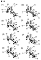
- FIG. 1 is an explanatory view showing tool and pot conveyance from a first magazine to a standby position in an automatic tool storage mechanism according to one embodiment of the present invention.
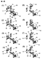
- FIG. 2 is an explanatory view showing conveyance of tools and pots from the standby position to the second magazine in the automatic tool storage mechanism shown in FIG.
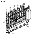
- FIG. 3 is a schematic perspective view showing an example of an automatic tool storage mechanism according to a preferred embodiment of the present invention.
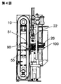
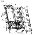
- FIG. 4 shows the relationship between one magazine of the automatic tool storage mechanism shown in FIG. 5 is a schematic perspective view showing the automatic tool storage mechanism shown in FIG. 6 is a schematic perspective view showing the automatic tool storage mechanism shown in FIG. 3 in a slightly enlarged manner.
- FIG. 7 is a diagram showing the relationship between the claw of the pot moving arm, the tool, and the pot, among the automatic tool storage mechanism shown in FIG.
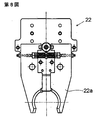
- FIG. 8 shows a pair of claws of the pot moving arm shown in FIG.
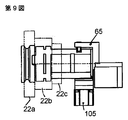
- FIG. 9 is a schematic top view showing three pairs of claws of the pot moving arm shown in FIG. 7.
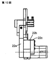
- 10 is a schematic side view showing three pairs of claws of the pot moving arm shown in FIG. 7.
- FIG. 1 shows a situation in which a tool and a pot before use are taken together from one magazine, conveyed to a standby position, and the tool before use and the tool after use on the spindle side are exchanged.
- FIG. 2 shows a situation in which the replaced tool and pot after use are returned together to another magazine.
- a pot also called a tool pot
- a pot is common to all tools (also called tool holders).
- the second magazine 16 is no. 51 to No. Houses up to 100 tools 18 (only one shown, others not shown) and pot 14.
- FIG. 1 (1) shows an example of the initial state. No. stored in the first magazine 10.
- One tool 12 is called by control means (not shown).
- the one tool 12 and the pot 14 therefor are taken out of the first magazine 10 together and transferred to the right in FIG.
- the pot moving arm 22 is lowered, and the No. 1 is moved by the plurality of claws of the pot moving arm 22. 1. Grab the V-shaped flange portion of the tool 12 and the pot 14.
- One tool 12 and pot 14 are moved to the entrance of guide 26.
- FIG. 1 shows a state where the tool change is completed.
- the 51 tool 18 and the pot 14 therefor move together to the left toward the entrance of the guide 26.
- tools 18 and the pot 14 are positioned below the pot moving arm 22.
- the pot moving arm 22 is moved by a plurality of claws. Grab the V-shaped flange part of 51 tool 18 and pot 14.
- the pot moving arm 22 is moved by a plurality of claws. In a state where the V-shaped flange portion of the tool 18 of 51 and the pot 14 are held, the pot moving arm 22 rises and returns to the initial position.
- the pot moving arm 22 moves to the position of the second magazine 16 while holding the tool 18 and the pot 14.
- the pot moving arm 22 holds the tool 18 and the pot 14 while holding the tool No. 2 in the second magazine 16.
- the 51 tool 18 is lowered to the return position.
- FIGS. 3 to 8 show one specific example of the automatic tool storage mechanism shown in FIGS.
- a plurality of (for example, five) magazines 10, 16, 40, 46, and 50 having the same basic configuration are arranged in a line in the vertical direction.
- a large number of pots 14 common to them are rotatably arranged so as to circulate in an endless manner.
- Various types of tools 12 and 18 (only two types are shown in FIGS. 1 and 2 as an example) are attached to each of the pots 14.
- the total number of pots 14 stored in all magazines can be several hundred (for example, 300).
- a specific pot 14 equipped with the tools 12 and 18 is selected (that is, called) by a control device (not shown), and a waiting means near the main shaft from the position 90 (FIG. 4) on the magazine side by a conveying means (described later). Transported to position 100.
- a first guide portion 51 on the magazine side that is conveyed and positioned in front of each of all the magazines, and a second provided between the first guide portion 51 and the standby position 100 at a predetermined position.
- the guide portion 26 constitutes a guide.
- the pot moving means includes a first driving means (preferably a hydraulic cylinder 55) for moving a pot with a tool, that is, a tool mounting pot, in a horizontal direction between the first guide portion 51 and each magazine, and a second guide portion.
- the tool mounting pot is moved in the vertical direction between the second guide means 101 (preferably a ball screw and a servo motor) for moving the tool mounting pot in the horizontal direction along the first guide portion 51 and the second guide portion 26.
- a pot moving arm 22 is provided.
- two rail-shaped pot moving arm travel guides 61 are arranged in parallel in the horizontal direction over both sides of the mechanism.
- a plurality of magazines 10 and the like are provided in a line along the pot moving arm travel guide 61.
- the pot moving arm 22 is moved up and down in the vertical direction or the up and down direction by an elevating drive unit 71.
- a traveling drive unit 77 (preferably including a speed reducer and a servo motor) via two belts 73 and 75 extending between both sides of the mechanism along the two pot moving arm traveling guides 61. Moves horizontally and stops at the selected magazine position.
- the first guide portion 51 can be set at desired vertical and horizontal positions. This will be described with reference to FIG.
- No. 1 is called (selected) by a control device (not shown), and the No. 1 tool 12 is set by the hydraulic cylinder 55 provided at the pot loading / unloading position of the magazine 10.
- One tool 12 and its pot 14 are pushed together from the first magazine 10 and transferred to the right in FIG. At that time, no.
- the pot 14 is gripped by the pot gripping portion 59 by the action of the pot lock cylinder 57 until the one tool 12 and the pot 14 therefor arrive at the lower position of the pot moving arm 22.
- the pot moving arm 22 is lowered and a plurality of claws such as No. Grab the V flange part of the tool 12 of 1 and grasp the two places of the pot 14 with the claws 22b and 22c.
- Reference numeral 103 denotes a pot lock cylinder for locking and gripping the tool and the pot 14 with the claws 22a, 22b and 22c.
- the pot moving arm 22 is raised, The first tool 12 and the pot 14 are moved together to the entrance of the second guide portion 26.
- the pot gripping portion 65 grips the pot 14 by the action of the pot lock cylinder 105.
- the pot 14 and the tool 12 attached thereto are conveyed to the standby position 100 by the second driving means 101. No. before use.
- the tool changing arm 28 is operated, and the pair of gripping portions 28a and 28b are rotated. 1 and the tool No. 1 after use attached to the spindle 30. 51 replaces the tool 18.
Landscapes
- Engineering & Computer Science (AREA)
- Mechanical Engineering (AREA)
- Automatic Tool Replacement In Machine Tools (AREA)
- Warehouses Or Storage Devices (AREA)
Abstract
Description
多数のツールとポットを収納したマガジンと、マガジンから所定のポットに装着されたツールを取り出して待機位置まで搬送する搬送手段と、その待機位置で待機中の使用前のツールと主軸側の使用後のツールとを交換する工具交換アームとを有する工具自動交換装置は公知である。例えば、Japanese Patent Laid−Open No.2003−291046及びJapanese Patent Laid−Open No.2008−155343を参照。
従来の自動工具交換装置においては、マガジンに配備されたものの中から呼び出された(選択された)ツールのV字フランジ部分を爪(ツメ)でつかみ、ポットからツールを取り出す。そして、そのポットはマガジンに残し、ツールのみをマガジンから待機位置まで搬送していた。
従来のように、ツールをポットから離して、ツールのV字フランジ部分のみをツメで把持した状態でツールを搬送すると、ツールが重い刃物や長い刃物である場合、ツールが搬送時に傾きやすくなり、とくに長い搬送路や高速度で、安定した搬送を行うことが困難になる。
ツールのV字フランジ部分を強く把持するためには、ツメは、高い剛性が必要となる。
図2は、図1に示す自動工具収納機構における待機位置から第2マガジンへのツール及びポットの搬送を示す説明図。
図3は、本発明の好ましい実施例による自動工具収納機構の一例を示す概略斜視図。
図4は、図3に示した自動工具収納機構の1つのマガジンと搬送手段との関係を示す。
図5は、図3に示す自動工具収納機構を少し拡大して示す概略斜視図。
図6は、図3に示す自動工具収納機構を少し拡大して示す概略斜視図。
図7は、図3に示す自動工具収納機構のうち、とくにポット移動アームのツメと、ツールおよびポットとの関係を示す図。
図8は、図7に示すポット移動アームの1対のツメを示す。
図9は、図7に示すポット移動アームの3対のツメを示す概略上面図。
図10は、図7に示すポット移動アームの3対のツメを示す概略側面図。
図1は、1つのマガジンから使用前のツールとポットを一緒に取り出して、それらを待機位置まで搬送し、その使用前のツールと、主軸側の使用後のツールとを交換する状況を示す。
図2は、交換された使用後のツールとポットを一緒に別のマガジンへ返却する状況を示す。
ポット(ツールポットともいう)は、すべてのツール(ツールホルダともいう)に共通のものを用いる。
図1~2の実施例においては、第1マガジン10がNo.1からNo.50までのツール12(1つのみ示し他は図示せず)とポット14を収納する。第2マガジン16がNo.51からNo.100までのツール18(1つのみ示し他は図示せず)とポット14を収納する。第1及び第2マガジン以外のマガジンは、図1~2には図示していない。
図1の(1)は初期状態の一例を示す。第1マガジン10に収納されたNo.1のツール12が制御手段(図示せず)によって呼び出される。
図1の(2)においては、その呼び出されたNo.1のツール12とそのためのポット14が一緒に第1マガジン10から取り出され、図1において右方向に移送されて、ポット移動アーム22の下方位置にくる。
図1の(3)においては、ポット移動アーム22が下降して、ポット移動アーム22の複数のツメによって、そのNo.1のツール12のV字フランジ部分とポット14をつかむ。
図1の(4)においては、ポット移動アーム22の上昇によってNo.1のツール12とポット14がガイド26の入口まで移動される。
図1の(5)では、複数のツメによってNo.1のツール12とポット14が保持されてガイド26の入口で停止した状態で、ポット移動アーム22だけが上昇して初期状態へ戻る。
図1の(6)では、No.1のツール12とポット14が保持された状態で、No.1のツール12とポット14が一緒にガイド26に沿って待機位置へ移動する。
図1の(7)では、工具交換アーム28が使用前のNo.1のツール12と主軸30側の使用後のNo.51のツール18とを交換する。
図1の(8)は工具交換完了の状態を示す。
図2の(1)においては、交換された使用後のNo.51のツール18とそのためのポット14が一緒にガイド26の入口に向けて左方向に移動する。
図2の(2)においては、使用後のNo.51のツール18とポット14がポット移動アーム22の下方位置にくる。
図2の(3)においては、ポット移動アーム22が、複数のツメによって、No.51のツール18のV字フランジ部分とポット14をつかむ。
図2の(4)においては、ポット移動アーム22が、複数のツメによって、No.51のツール18のV字フランジ部分とポット14をつかんだ状態で、ポット移動アーム22が上昇して初期位置に戻る。
図2の(5)においては、ポット移動アーム22が、ツール18とポット14をつかんだまま、第2マガジン16の位置に移動する。
図2の(6)においては、ポット移動アーム22が、ツール18とポット14をつかんだまま、第2マガジン16におけるNo.51のツール18の返却位置へ下降する。
図2の(7)においては、ツール18とポット14から離れて、ポット移動アーム22のみが初期状態の位置へ上昇する。
図2の(8)においては、No.51のツール18がポット14と一緒に第2マガジン16に返却される。その結果、全体が初期状態に戻る。
図3~8は、図1~2に示した自動工具収納機構の具体例の1つを示す。
同じ基本構成の複数(例えば5つ)のマガジン10、16、40、46、50が縦向きに一列に並べて配置されている。
各マガジン10、16、40、46、50には、それらに共通の多数のポット14がエンドレスの形で周回するように回動自在に配置されている。それらのポット14の各々に1つずつ種々のツール12、18(図1~2には2種類のみ例示的に示した)が装着されている。
全マガジンに収納するポット14の総数は、数百(例えば300)にすることができる。
ツール12、18を装着した特定のポット14が、制御装置(図示せず)によって選択され(つまり呼び出され)、搬送手段(後述)によって、マガジン側の位置90(図4)から主軸近くの待機位置100まで搬送される。
ポット搬送のために、全マガジンの各々の前方に搬送されて位置決めされるマガジン側の第1ガイド部分51と、所定の位置で第1ガイド部分51と待機位置100との間に設けられる第2ガイド部分26とが、ガイドを構成している。
ポット移動手段は、ツールを装着したポット、つまりツール装着ポットを第1ガイド部分51と各マガジンとの間で水平方向に移動させる第1駆動手段(好ましくは油圧シリンダ55)と、第2ガイド部分26に沿ってツール装着ポットを水平方向に移動させる第2駆動手段101(好ましくはボールネジ及びサーボモータ)と、第1ガイド部分51及び第2ガイド部分26間でツール装着ポットを垂直方向に移動させるポット移動アーム22を有する。
図5によく示されているように、2本のレール状のポット移動アーム走行用ガイド61が機構の両側にわたって水平方向に平行に配置されている。それらのポット移動アーム走行用ガイド61に沿って複数のマガジン10その他が一列に並んで設けられている。
ポット移動アーム22は、昇降用駆動部71によって垂直方向又は上下方向に昇降される。
2本のポット移動アーム走行用ガイド61に沿って、機構の両側間に延設された2本のベルト73、75を介して走行用駆動部77(好ましくは減速機とサーボモータを含む)によって水平方向に移動され、選択されたマガジンの位置で停止する。
2本のポット移動アーム走行用ガイド61とポット移動アーム22によって、第1ガイド部分51は所望の縦方向と横方向の位置に設定できる。
図6を参照して説明する。
第1マガジン10に収納されている多数のツールのうち、No.1のツール12が制御装置(図示せず)によって呼び出され(選択され)、マガジン10のポット出し入れ位置に設けられた油圧シリンダ55によって、そのNo.1のツール12とそれ用のポット14が一緒に第1マガジン10から押し出され、第1ガイド部分51に沿って、図6において右方向に移送される。その際、No.1のツール12とそれ用のポット14がポット移動アーム22の下方位置に到来するまで、ポットロックシリンダ57の作用で、ポット14はポット把持部59によって把持される。
次に、ポット移動アーム22を下降させて、複数のツメで、例えば、ツメ22aでNo.1のツール12のVフランジ部分をつかみ、ツメ22b、22cでポット14の2箇所をつかむ。
符号103は、ツメ22a、22b、22cでツールとポット14をロックして把持するためのポットロックシリンダを示す。
ポットロックシリンダ103を作動させて「ロック」状態にしたまま、ポット移動アーム22を上昇させて、No.1のツール12とポット14を一緒に第2ガイド部分26の入口に移動させる。
第2ガイド部分26の入口において、ポット把持部65がポットロックシリンダ105の作用でポット14を把持する。ポット14が把持された状態で、ポット14とそこに装着されたツール12が第2駆動手段101によって待機位置100まで搬送されていく。
使用前のNo.1のツール12とポット14が待機位置100に到来したあと、工具交換アーム28が作動し、1対の把持部28a、28bが回動し、待機位置100に存在する使用前のNo.1のツール12と、主軸30に装着されている使用後のNo.51にツール18とが交換される。つまり、No.1のツール12をポット14から取り外すとともに、No.51のツール18を主軸30から取り外し、そのあと、それらを180°回転させ、さらに、No.1のツール12を主軸30に装着するとともに、No.51のツール18をポット18に装着する。
使用後のNo.51のツール18とポット14は、図2に示されているように、ガイドに沿って所定のマガジンに向けて搬送される。その際、ポットロックシリンダ103、105、ポット移動アーム22、把持部59、65、油圧シリンダ55その他は、ポット14がマガジンから待機位置100まで搬送されてきたときとは逆の順序で同様の動作をする。
前述のembodimentsによれば、マガジンと待機位置100との間でツールとポットがつねに一緒になっており、ポットがサポートされる。
Claims (9)
- ツールを装着したポットが数多く収納された少なくとも1つのマガジンと、
マガジン側の位置と主軸近くの待機位置との間で1つずつツールを装着したポットを搬送する搬送手段と、
待機位置で待機中のポットから使用前のツールを取り出して主軸に装着するとともに、主軸に装着されていた使用後のツールを主軸から取り出してポットに装着する工具交換アームと
を有する自動工具収納機構。 - 搬送手段が、マガジン側の位置と主軸近くの待機位置との間に設けられたガイドと、ツールを装着したポットをガイドに沿って移動させるポット移動手段を有することを特徴とする請求項1に記載の自動工具収納機構。
- ガイドが、マガジン側の第1ガイド部分と、第1ガイド部分と待機位置との間でツールを装着したポットをガイドする第2ガイド部分を有することを特徴とする請求項2に記載の自動工具収納機構。
- ポット移動手段が、ツールを装着したポットを第1ガイド部分とマガジンとの間で移動する油圧シリンダと、ツールを装着したポットを移動するボールネジ及びサーボモータとを有することを特徴とする請求項2に記載の自動工具収納機構。
- さらに、ポット移動手段が、ツールを装着したポットを第1ガイド部分と第2ガイド部分との間で移動するポット移動アームを有することを特徴とする請求項2又は4記載の自動工具収納機構。
- 複数のマガジンが、ポット移動アーム走行用ガイドに沿って並んで配置されており、ポット移動アームをポット移動アーム走行用ガイド上で走行させる駆動手段が設けられており、選択された1つのマガジンのところでポット移動アームを停止して、そのマガジンと第1ガイド部分との間で、ツールを装着したポットを移動することを特徴とする請求項5に記載の自動工具収納機構。
- 複数のマガジンに収納されるポットの総数が数百であることを特徴とする請求項6に記載の自動工具収納機構。
- ポット移動アームがベルトの使用によってポット移動アーム走行用ガイドに沿って走行することを特徴とする請求項6に記載の自動工具収納機構。
- ポット移動アームが、ポットをつかむツメとツールをつかむツメを有することを特徴とする請求項6又は8に記載の自動工具収納機構。
Priority Applications (4)
| Application Number | Priority Date | Filing Date | Title |
|---|---|---|---|
| US13/055,050 US8360945B2 (en) | 2009-04-22 | 2010-04-20 | Automatic tool storing mechanism |
| EP10767187.7A EP2422924B1 (en) | 2009-04-22 | 2010-04-20 | Automatic tool storage mechanism |
| KR1020117003676A KR101232007B1 (ko) | 2009-04-22 | 2010-04-20 | 자동공구 수납기구 |
| CN2010800021313A CN102099152B (zh) | 2009-04-22 | 2010-04-20 | 自动工具收容机构 |
Applications Claiming Priority (2)
| Application Number | Priority Date | Filing Date | Title |
|---|---|---|---|
| JP2009-104249 | 2009-04-22 | ||
| JP2009104249A JP4972120B2 (ja) | 2009-04-22 | 2009-04-22 | 自動工具収納機構 |
Publications (1)
| Publication Number | Publication Date |
|---|---|
| WO2010123135A1 true WO2010123135A1 (ja) | 2010-10-28 |
Family
ID=43011246
Family Applications (1)
| Application Number | Title | Priority Date | Filing Date |
|---|---|---|---|
| PCT/JP2010/057321 Ceased WO2010123135A1 (ja) | 2009-04-22 | 2010-04-20 | 自動工具収納機構 |
Country Status (7)
| Country | Link |
|---|---|
| US (1) | US8360945B2 (ja) |
| EP (1) | EP2422924B1 (ja) |
| JP (1) | JP4972120B2 (ja) |
| KR (1) | KR101232007B1 (ja) |
| CN (1) | CN102099152B (ja) |
| TW (1) | TWI392559B (ja) |
| WO (1) | WO2010123135A1 (ja) |
Cited By (3)
| Publication number | Priority date | Publication date | Assignee | Title |
|---|---|---|---|---|
| US20130095988A1 (en) * | 2011-04-05 | 2013-04-18 | Deckel Maho Pfronten Gmbh | Tool handling device for machine tools |
| US20130260973A1 (en) * | 2010-12-13 | 2013-10-03 | Doosan Infracore Co., Ltd. | Tool carrier unit of a tool magazine |
| TWI630979B (zh) * | 2015-05-29 | 2018-08-01 | 東芝機械股份有限公司 | 工作機械 |
Families Citing this family (6)
| Publication number | Priority date | Publication date | Assignee | Title |
|---|---|---|---|---|
| TW201302376A (zh) * | 2011-07-13 | 2013-01-16 | Jian Xue Qin | Cnc綜合加工機自動換刀機構 |
| KR101383442B1 (ko) * | 2012-06-14 | 2014-04-08 | 주식회사 성산암데코 | 자동차 브레이크 시스템의 캘리퍼 하우징 가공용 고속 툴 체인저 |
| JP5667254B1 (ja) | 2013-08-02 | 2015-02-12 | キタムラ機械株式会社 | 自動工具収納機構 |
| CN104191290B (zh) * | 2014-08-25 | 2016-03-30 | 无锡众望四维科技有限公司 | 锁芯专用夹紧装置 |
| JP6342940B2 (ja) * | 2016-04-19 | 2018-06-13 | キタムラ機械株式会社 | 工作機械用自動工具交換システム |
| JP6998158B2 (ja) * | 2017-09-07 | 2022-01-18 | 株式会社ディスコ | 切削ブレード供給装置 |
Citations (7)
| Publication number | Priority date | Publication date | Assignee | Title |
|---|---|---|---|---|
| JPH0438335U (ja) * | 1990-07-31 | 1992-03-31 | ||
| JP2001038561A (ja) * | 1999-07-27 | 2001-02-13 | Toshiba Mach Co Ltd | マトリックス形工具マガジン |
| JP2002355729A (ja) * | 2001-05-30 | 2002-12-10 | Hitachi Seiki Co Ltd | 工作機械の自動工具交換装置 |
| JP2003291046A (ja) | 2002-03-29 | 2003-10-14 | Toyoda Mach Works Ltd | 自動工具交換装置 |
| JP2004276161A (ja) * | 2003-03-14 | 2004-10-07 | Kitamura Mach Co Ltd | ツールホルダ交換機構 |
| JP2005103653A (ja) * | 2003-09-26 | 2005-04-21 | Makino Milling Mach Co Ltd | 自動工具交換装置 |
| JP2008155343A (ja) | 2006-12-26 | 2008-07-10 | Kitamura Mach Co Ltd | 工具交換方法及びマシニングセンター |
Family Cites Families (18)
| Publication number | Priority date | Publication date | Assignee | Title |
|---|---|---|---|---|
| JPS50112874A (ja) * | 1974-02-18 | 1975-09-04 | ||
| JPS5726897B2 (ja) * | 1974-04-30 | 1982-06-07 | ||
| IT1037252B (it) * | 1975-04-14 | 1979-11-10 | Mandelli Spa | Macchina utensile conportante un unico mandrino atto ad assumere automaticamente siala posizione orizzontale quella verticale ed un unico dispositivo di cambio automatico degli utnesili |
| AR225485A1 (es) * | 1980-02-08 | 1982-03-31 | Oerlikon Buehrle Ag | Una maquina-herramienta |
| JPS56157935A (en) * | 1980-05-09 | 1981-12-05 | Kurashiki Kikai Kk | Tool magazine at machining center |
| JPS61142038A (ja) * | 1984-12-12 | 1986-06-28 | Toshiba Mach Co Ltd | アタツチメント工具交換装置 |
| JPS62199333A (ja) * | 1986-02-26 | 1987-09-03 | Okuma Mach Works Ltd | 工作機械における工具交換方法 |
| JPH01240244A (ja) * | 1988-03-18 | 1989-09-25 | Nkk Corp | Nc工作機における工具交換方法及びそのための装置 |
| JPH0438335A (ja) | 1990-06-05 | 1992-02-07 | Mitsubishi Electric Corp | 屋外水配管凍結防止装置 |
| JP3642069B2 (ja) * | 1994-03-09 | 2005-04-27 | 豊田工機株式会社 | 自動工具交換装置 |
| JP3246647B2 (ja) * | 1996-03-12 | 2002-01-15 | キタムラ機械株式会社 | 自動工具交換用ツールマガジン |
| JP3177766B2 (ja) * | 1996-04-18 | 2001-06-18 | オークマ株式会社 | 工具搬送装置 |
| GB2331946B (en) * | 1997-12-02 | 1999-10-20 | Nippei Toyama Corp | Tool change method and tool change device |
| JP2002355728A (ja) * | 2001-05-30 | 2002-12-10 | Howa Mach Ltd | 工作機械の工具マガジン装置 |
| AT504172B1 (de) * | 2006-09-14 | 2009-08-15 | Miguel Muser | Vorrichtung zum be- und entladen einer werkzeugmaschine |
| JP2008149416A (ja) * | 2006-12-19 | 2008-07-03 | Nisshinbo Ind Inc | マシニングセンタ |
| JP5082591B2 (ja) * | 2007-05-31 | 2012-11-28 | ブラザー工業株式会社 | 工具交換装置 |
| US7635327B1 (en) * | 2009-04-02 | 2009-12-22 | Quaser Machine Tools, Inc. | Multi-layered tool magazine of CNC machine |
-
2009
- 2009-04-22 JP JP2009104249A patent/JP4972120B2/ja active Active
- 2009-11-19 TW TW098139367A patent/TWI392559B/zh not_active IP Right Cessation
-
2010
- 2010-04-20 KR KR1020117003676A patent/KR101232007B1/ko active Active
- 2010-04-20 EP EP10767187.7A patent/EP2422924B1/en active Active
- 2010-04-20 CN CN2010800021313A patent/CN102099152B/zh not_active Expired - Fee Related
- 2010-04-20 WO PCT/JP2010/057321 patent/WO2010123135A1/ja not_active Ceased
- 2010-04-20 US US13/055,050 patent/US8360945B2/en active Active
Patent Citations (7)
| Publication number | Priority date | Publication date | Assignee | Title |
|---|---|---|---|---|
| JPH0438335U (ja) * | 1990-07-31 | 1992-03-31 | ||
| JP2001038561A (ja) * | 1999-07-27 | 2001-02-13 | Toshiba Mach Co Ltd | マトリックス形工具マガジン |
| JP2002355729A (ja) * | 2001-05-30 | 2002-12-10 | Hitachi Seiki Co Ltd | 工作機械の自動工具交換装置 |
| JP2003291046A (ja) | 2002-03-29 | 2003-10-14 | Toyoda Mach Works Ltd | 自動工具交換装置 |
| JP2004276161A (ja) * | 2003-03-14 | 2004-10-07 | Kitamura Mach Co Ltd | ツールホルダ交換機構 |
| JP2005103653A (ja) * | 2003-09-26 | 2005-04-21 | Makino Milling Mach Co Ltd | 自動工具交換装置 |
| JP2008155343A (ja) | 2006-12-26 | 2008-07-10 | Kitamura Mach Co Ltd | 工具交換方法及びマシニングセンター |
Non-Patent Citations (1)
| Title |
|---|
| See also references of EP2422924A4 * |
Cited By (6)
| Publication number | Priority date | Publication date | Assignee | Title |
|---|---|---|---|---|
| US20130260973A1 (en) * | 2010-12-13 | 2013-10-03 | Doosan Infracore Co., Ltd. | Tool carrier unit of a tool magazine |
| US9333609B2 (en) * | 2010-12-13 | 2016-05-10 | Doosan Infracore Co., Ltd. | Tool carrier unit of a tool magazine |
| US20130095988A1 (en) * | 2011-04-05 | 2013-04-18 | Deckel Maho Pfronten Gmbh | Tool handling device for machine tools |
| US8758208B2 (en) * | 2011-04-05 | 2014-06-24 | Deckel Maho Pfronten Gmbh | Tool handling device for machine tools |
| TWI630979B (zh) * | 2015-05-29 | 2018-08-01 | 東芝機械股份有限公司 | 工作機械 |
| US10086485B2 (en) | 2015-05-29 | 2018-10-02 | Toshiba Kikai Kabushiki Kaisha | Machine tool |
Also Published As
| Publication number | Publication date |
|---|---|
| TW201038356A (en) | 2010-11-01 |
| CN102099152A (zh) | 2011-06-15 |
| EP2422924B1 (en) | 2014-07-23 |
| EP2422924A4 (en) | 2013-05-29 |
| EP2422924A1 (en) | 2012-02-29 |
| KR20120014549A (ko) | 2012-02-17 |
| JP2010253588A (ja) | 2010-11-11 |
| US20120028771A1 (en) | 2012-02-02 |
| JP4972120B2 (ja) | 2012-07-11 |
| CN102099152B (zh) | 2013-11-06 |
| TWI392559B (zh) | 2013-04-11 |
| US8360945B2 (en) | 2013-01-29 |
| KR101232007B1 (ko) | 2013-02-08 |
Similar Documents
| Publication | Publication Date | Title |
|---|---|---|
| JP5667254B1 (ja) | 自動工具収納機構 | |
| JP4972120B2 (ja) | 自動工具収納機構 | |
| CN110461539B (zh) | 机床 | |
| JP5106783B2 (ja) | 棚式倉庫及び荷役方法 | |
| JP2011178563A (ja) | 収納ラック | |
| KR101824069B1 (ko) | 와이어 본더 물류 설비 및 그의 매거진 이송방법 | |
| JP2010253588A5 (ja) | ||
| CN113939462A (zh) | 用于机床的分拣系统、机床以及用于分拣切割零件的方法 | |
| JP2013111742A (ja) | シャフト状のワークピースを加工するための工作機械 | |
| CN218370422U (zh) | 工件转移装置及加工设备的自动上下料系统 | |
| KR102293463B1 (ko) | 반송장치 | |
| CN106573352A (zh) | 加工中心 | |
| CN218143647U (zh) | 晶圆存储智能仓 | |
| JP2005118930A (ja) | 加工セル | |
| CN111591658B (zh) | 一种储刀配刀系统 | |
| US9969037B2 (en) | Dual-spindle machining apparatus | |
| US20060075625A1 (en) | Multiple side processing machine and positioning device for a workpiece | |
| ITMO20100099A1 (it) | Centro di lavorazione | |
| ES2985709T3 (es) | Máquina de mecanizado para lentes ópticas e instalación de fabricación con la misma | |
| EP4480633A1 (en) | Manipulating device for extracting workpieces from cnc lathe and placing them on pallets | |
| JP2009056546A (ja) | 工作機械 | |
| JPH0538663A (ja) | 旋盤セル | |
| JPH0455822B2 (ja) | ||
| CN120051350A (zh) | 工件搬出搬入装置和工件搬出搬入装置的控制方法 | |
| JP2000005961A (ja) | 工具マガジン |
Legal Events
| Date | Code | Title | Description |
|---|---|---|---|
| WWE | Wipo information: entry into national phase |
Ref document number: 201080002131.3 Country of ref document: CN |
|
| WWE | Wipo information: entry into national phase |
Ref document number: 2010767187 Country of ref document: EP |
|
| 121 | Ep: the epo has been informed by wipo that ep was designated in this application |
Ref document number: 10767187 Country of ref document: EP Kind code of ref document: A1 |
|
| WWE | Wipo information: entry into national phase |
Ref document number: 13055050 Country of ref document: US |
|
| ENP | Entry into the national phase |
Ref document number: 20117003676 Country of ref document: KR Kind code of ref document: A |
|
| NENP | Non-entry into the national phase |
Ref country code: DE |