WO2010143325A1 - 塗布具 - Google Patents
塗布具 Download PDFInfo
- Publication number
- WO2010143325A1 WO2010143325A1 PCT/JP2009/071281 JP2009071281W WO2010143325A1 WO 2010143325 A1 WO2010143325 A1 WO 2010143325A1 JP 2009071281 W JP2009071281 W JP 2009071281W WO 2010143325 A1 WO2010143325 A1 WO 2010143325A1
- Authority
- WO
- WIPO (PCT)
- Prior art keywords
- coating liquid
- guiding member
- liquid guiding
- tip
- insertion hole
- Prior art date
- Legal status (The legal status is an assumption and is not a legal conclusion. Google has not performed a legal analysis and makes no representation as to the accuracy of the status listed.)
- Ceased
Links
Images


Classifications
-
- A—HUMAN NECESSITIES
- A45—HAND OR TRAVELLING ARTICLES
- A45D—HAIRDRESSING OR SHAVING EQUIPMENT; EQUIPMENT FOR COSMETICS OR COSMETIC TREATMENTS, e.g. FOR MANICURING OR PEDICURING
- A45D34/00—Containers or accessories specially adapted for handling liquid toiletry or cosmetic substances, e.g. perfumes
- A45D34/04—Appliances specially adapted for applying liquid, e.g. using roller or ball
- A45D34/042—Appliances specially adapted for applying liquid, e.g. using roller or ball using a brush or the like
-
- A—HUMAN NECESSITIES
- A46—BRUSHWARE
- A46B—BRUSHES
- A46B11/00—Brushes with reservoir or other means for applying substances, e.g. paints, pastes, water
- A46B11/001—Brushes with reservoir or other means for applying substances, e.g. paints, pastes, water with integral reservoirs
- A46B11/0013—Brushes with reservoir or other means for applying substances, e.g. paints, pastes, water with integral reservoirs dispensing by gravity or by shaking
-
- B—PERFORMING OPERATIONS; TRANSPORTING
- B43—WRITING OR DRAWING IMPLEMENTS; BUREAU ACCESSORIES
- B43K—IMPLEMENTS FOR WRITING OR DRAWING
- B43K8/00—Pens with writing-points other than nibs or balls
- B43K8/02—Pens with writing-points other than nibs or balls with writing-points comprising fibres, felt, or similar porous or capillary material
-
- B—PERFORMING OPERATIONS; TRANSPORTING
- B43—WRITING OR DRAWING IMPLEMENTS; BUREAU ACCESSORIES
- B43K—IMPLEMENTS FOR WRITING OR DRAWING
- B43K8/00—Pens with writing-points other than nibs or balls
- B43K8/02—Pens with writing-points other than nibs or balls with writing-points comprising fibres, felt, or similar porous or capillary material
- B43K8/04—Arrangements for feeding ink to writing-points
Definitions
- the present invention relates to an applicator for applying an application liquid such as ink or cosmetic liquid, such as a writing instrument such as a brush pen or a cosmetic tool.
- an application liquid such as ink or cosmetic liquid
- a writing instrument such as a brush pen or a cosmetic tool.
- various kinds of applicators are conventionally used as an applicator for applying a coating liquid such as ink or cosmetic liquid to a coating medium, such as a writing instrument such as a brush pen or a cosmetic tool.
- a coating liquid such as ink or cosmetic liquid
- a writing instrument such as a brush pen or a cosmetic tool.
- paper is used as the application medium
- cosmetic tools the peripheral part of the eyes of the face is the application medium.
- there is a brush that has been used since ancient times, and the brush is a seemingly primitive writing instrument in that it requires the work of attaching ink to the tip of the brush, but the characteristics required for the writing instrument Is fully considered.
- the tip of the brush follows the movement of the brush body in both the static state of “stop” and the dynamic state of “splash” and “bend”, or
- the fact that the adhered ink is satisfactorily supplied from the root part of the hair tip to the tip part side is a suitable example in which the brush has the characteristics necessary for the writing instrument.
- Good brush conditions include sharp hair tips, straight and well-aligned hair, fluffy hair tips, elasticity, etc. "It is soft and has good ink.”
- hairiness refers to the operability of transmitting the movement of the hand to the brush tip
- “includes” refers to the property of transmission to the tip side of the ink.
- Brushes with moderately soft fur have sharp hair tips, and the tips of the brushes do not scatter during carrying, and are rich in elasticity.
- a brush with good “include” has characteristics such as good transmission and adjustment that can supply black ink continuously as a supply source.
- General brushes have a function of “contains” by storing the ink in the root part of the hair tip, and the root part of the hair tip is a replenishing part of the ink, and at the same time the ink is rapidly applied to the tip side. It also fulfills the function of supplying.
- brush pens have a permanent liquid replenishment unit, such as an ink reservoir, so that the hair tip basically has the function of "contains". There is no need.
- the brush pen is provided with a liquid replenishment portion (ink storage portion) at a position away from the hair tip, which is the writing portion, so that the function of rapidly supplying ink to the tip side becomes insufficient. There is a fear.
- a brush pen it is impossible to realize a writing taste like an old brush, and therefore, each of the fibers constituting the hair tip is tapered. However, it has been found that such a taper further reduces the function of supplying ink to the tip side.
- Lucas Washburn equation (1) is often used for the liquid penetration rate between fibers.
- X is the reach distance of the liquid
- ⁇ is the viscosity of the liquid
- D is the average diameter of the flow path formed between the fibers
- t is the elapsed time
- ⁇ is the surface tension of the liquid
- ⁇ is the liquid The contact angle with the fiber.
- FIG. 12 is a graph in which the vertical axis represents the liquid penetration amount Q and the horizontal axis represents the liquid movement distance X, but the fiber is tapered compared to the curve a when the fiber is not tapered.
- the curve b shows that the amount Q of liquid permeation rapidly decreases.
- the graph of FIG. 12 expresses the balance between the driving force of the capillary force between the fibers and the deceleration effect due to the fluid resistance generated in the flow path.
- the fibers are tapered, Even when the taper is not tapered, when ink is supplied from the liquid reservoir to the tip of the hair like a brush pen, the liquid flow path length is long. It has been shown that there is a disadvantage in terms of ink supply compared to those with a liquid supply source. Further, according to the above formula (1), it is shown that when the liquid viscosity ⁇ increases, the moving distance of the liquid decreases, and when the viscosity of the ink is large, the moving speed cannot be sufficiently obtained and the blurring phenomenon may be caused. There is also the possibility of deposition during the supply.
- an ink guiding portion or a pipe called a relay core is provided in the center portion of the hair tip from the ink storage portion in order to supply liquid (ink) to a portion close to the writing portion.
- a brush pen that can supply ink to the hair tip has also been developed.
- patent applications relating to a brush pen having a structure having such a relay core for example, applications shown in Patent Documents 1 to 3 below have been filed.
- a brush pen having a structure with such a relay core can follow the rapid ink supply because the supply mechanism is close to the writing part.
- the present invention has been made in order to solve the above-described problems, and there is no risk of the above-described cracking of the hair tip, and the coating liquid can be reliably guided to the hair tip side.
- Another object of the present invention is to make it possible to make the hair ends thinner while maintaining these functions.
- the present invention has been made to solve such a problem, and in an applicator having a hair tip that can be impregnated with a coating solution and can apply the coating solution to a coating medium, the coating solution is applied to the hair tip side.
- the present invention provides an applicator characterized in that a coating liquid guiding member capable of guiding the liquid is provided.
- the application liquid can supply the application liquid to the hair end side by the application liquid guiding member, and therefore, the central part of the hair tip like the conventional applicator. It is not necessary to provide a relay core located at the center, and as a result, it is possible to reliably prevent inadvertent cracking or the like of the hair tip that may have occurred by providing such a relay core.
- the coating liquid guiding member is configured to be able to supply the coating liquid to the hair tip side
- the coating liquid guiding member and the hair tip are compared with those of the conventional structure in which the relay core is provided.
- the contact area with the tip of the hair can be increased, and the moving distance of the coating liquid to the hair tip can be shortened structurally, so that the coating liquid can be reliably guided to the hair tip portion.
- the application of is not defective.
- the coating liquid guiding member is configured to be able to supply the coating liquid to the hair tip side, and a conventional relay core is not required, so that the hair tip can be formed thinner than the conventional one. .
- a conventional face brush has a thin tip, so it has been necessary to lengthen the tip to have a storage function at the root, but in the present invention, a writing instrument such as a brush pen with a short tip is thin. It becomes possible to provide.
- the coating liquid guiding member is formed with an insertion hole for inserting a hair tip.
- the coating liquid guiding member is preferably formed with a coating liquid guiding hole that can guide the coating liquid to the insertion hole side by capillary action in communication with the insertion hole.
- the coating liquid is induced by the capillary phenomenon in the coating liquid guiding hole of the coating liquid guiding member, and further guided from the coating liquid guiding hole to the insertion hole.
- the capillary phenomenon By this, the coating liquid guided through the coating liquid guiding hole is impregnated in the hair ends inserted into the insertion holes. Accordingly, the coating liquid is reliably guided from the coating liquid guiding member to the hair tip side.
- the coating liquid guiding hole is composed of, for example, a plurality of pores formed radially from the insertion hole toward the outside centering on the insertion hole. With this configuration, the capillary phenomenon can be more suitably exhibited.
- the coating liquid guiding member formed by communicating the coating liquid guiding hole with such an insertion hole is formed of, for example, a synthetic resin molded body.
- the coating liquid guiding member can be easily manufactured even if the coating liquid guiding hole has a complicated shape that causes capillary action.
- the insertion hole of the coating liquid guiding member is preferably formed by opening an opening on the distal end side from which the tip of the hair tip protrudes and an opening so that the rear end of the hair tip can come into contact with the coating liquid. It is formed so as to penetrate through the opening on the end side.
- a stopper that is wider than the opening on the rear end side of the coating liquid guiding member is preferably provided on the rear end side of the hair tip so that it can be locked to the rear end surface side of the coating liquid guiding member. It is formed.
- the hair tip is preferably configured by bundling a plurality of tapered fibers. Further, the inner peripheral surface of the insertion hole of the coating liquid guiding member is formed in a tapered shape that is narrower toward the tip side.
- the insertion hole of the coating liquid guiding member is formed in a narrow taper shape from the rear end side to the front end side of the insertion hole, the front end from the rear end side of the insertion hole Also in the direction toward the part side, the induction of the coating liquid is performed in a good state, and as a result, the supply of the coating liquid to the tip end side of the hair end is performed in a good state. Furthermore, the insertion hole of the coating liquid guiding member is formed in a narrow taper shape from the rear end side to the front end side, and a hair tip constituted by bundling a plurality of tapered fibers is inserted into the insertion hole.
- the hair ends When the hair ends are inserted into the coating liquid guiding member in close contact with each other, there is no risk of a gap between the hair tips and the coating liquid guiding member. As a result, the hair ends become the coating liquid guiding member. It will be securely fixed to. Moreover, a stable hair tip with a sharp point is obtained by inserting the hair tip into the coating liquid guiding member in a close contact state. Furthermore, by inserting the bristles into the coating liquid guiding member in a close contact state, the bristles and the coating liquid guiding member are in an integrated state, and as a result, when contacting the coating medium, etc. The operability of the applicator is improved.
- the coating liquid guiding member is preferably made of a porous material. With this configuration, the coating liquid is absorbed by the coating liquid guiding member composed of the porous material, and the coating liquid is supplied from the peripheral side to the hair tip by the coating liquid guiding member more smoothly. Will occur.
- the coating liquid guiding member is made of a porous material
- the pore diameter is preferably 20 to 80 ⁇ m. Examples of the porous material include a sintered resin, a foamable synthetic resin, a ceramic foam, a foam metal, a sintered metal porous body, and the like.
- the coating liquid guiding member is preferably configured to have flexibility. With this configuration, for example, when the hair tip comes into contact with an application medium such as paper and bends, the coating liquid guiding member is also easily bent with the hair tip, and the operability of the applicator is further improved.
- the insertion hole can also be formed as a concave shape having no opening on the rear end side.
- the bristles are preferably inserted so as to be in surface contact with the inner peripheral surface of the insertion hole of the coating liquid guiding member 4.
- the coating liquid can be reliably guided to the hair tip side, and the liquid supply to the tip end side of the hair tip is also performed in a good state. Therefore, it is possible to provide an applicator that can apply the coating liquid in a good state.
- the coating liquid guiding member is configured to be able to supply the coating liquid to the hair tip side
- the hair tip can be formed thinner than the conventional one from the structure, for example, a face brush
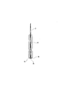
- FIG. 2 is a sectional view taken along line AA in FIG. 1.
- Sectional drawing of other embodiment which shows the fixing means of a coating liquid guide member and a hair tip.
- Sectional drawing of other embodiment which shows the fixing means of a coating liquid guide member and a hair tip.
- Sectional drawing of the applicator of other embodiment Sectional drawing of the applicator of other embodiment.
- the graph which shows the correlation with the osmosis
- the applicator of the present invention can be impregnated with the application liquid, and in the applicator having a hair tip capable of applying the application liquid to the application medium, the application liquid capable of inducing the application liquid toward the hair tip side. It consists of a structure provided with a guide member.
- the material of the hair tip is not particularly limited, and for example, polyester fibers such as polyethylene terephthalate and polybutylene terephthalate, and synthetic fibers such as polyamide fibers are used. It is desirable that the bristles are formed by bundling a plurality of tapered fibers.
- the material of the coating liquid guiding member is not particularly limited.
- synthetic fibers are aggregated and bonded with a binder, expandable synthetic resin having open cells, porous injection molding resin, sintered resin, etc.
- ceramic foam, foam metal, sintered metal porous body, and the like can also be used.
- a thing like a synthetic resin molded body can also be used.
- it is desirable to be composed of a porous material such as a sintered resin, a porous injection molded resin, a foamable synthetic resin having open cells, a ceramic foam, a foam metal, a sintered metal porous body, It is desirable to be composed of sintered resin, porous injection molding resin, foamable synthetic resin having open cells, and the like.
- the sintered resin can be formed by sintering resin powder (resin fine particles), and as described above, the insertion hole of the coating liquid guiding member has a narrow taper shape toward the tip side. It can be easily formed into a shape. Moreover, it is convenient also when forming so that a coating liquid guide member may have flexibility. Furthermore, it is excellent also in the effect
- thermoplastic resins such as polyethylene, polypropylene, polytetrafluoroethylene, polyamide, and polyacetal, and thermosetting resins such as phenol resin can be used.
- polyethylene can be preferably used.
- ultra high molecular weight polyethylene, high density polyethylene, low density polyethylene and the like can be used.
- the sintered resin is produced by sintering resin powder (resin fine particles), and the resin fine particles having a particle diameter of 1 to 100 ⁇ m are used. It is desirable to use one having a thickness of 5 to 30 ⁇ m.
- the porosity is preferably about 20 to 50%, more preferably about 30 to 50%.
- the temperature during heating is set according to the melting point of each resin, and the heating time can be any time such as 10 minutes to 3 hours.
- the pore diameter of the porous material is preferably 20 to 80 ⁇ m.
- Ordinary pigments have a primary particle size of 20 to 100 nm and a dispersed particle size of about 0.06 to 6 ⁇ m, and a kind of lame pearl is close to several ⁇ m, and these various inks do not cause a color change. Therefore, it is desirable that the average pore diameter of the porous resin constituting the coating liquid guiding member is about 20 ⁇ m to 80 ⁇ m.
- the coating liquid guiding member is preferably configured to have flexibility.
- the attachment of the hair tip to the coating liquid guiding member is performed, for example, by forming an insertion hole in the coating liquid guiding member and inserting the hair tip into the insertion hole.
- the insertion hole of the coating liquid guiding member penetrates, for example, an opening on the front end side from which the bristles protrude and a rear end side opening formed so that the bristles can come into contact with the coating liquid. It is shaped like an insertion hole formed in this way. Alternatively, in addition to such an insertion hole, it may be formed as a concave shape having no rear end side opening.
- the hair tips are inserted so as to be in surface contact with the inner peripheral surface of the insertion hole of the coating liquid guiding member.
- the coating liquid impregnated and held in the coating liquid guiding member is supplied to the hair tip from the peripheral portion side of the hair tip in the surface contact state.
- the inner peripheral surface of the insertion hole of the coating liquid guiding member can be formed in a tapered shape that is narrower toward the tip side.
- the inner peripheral surface of the insertion hole of the coating liquid guiding member is formed in a tapered shape, and further, a plurality of tapered fibers are bundled to form a hair tip, thereby forming the inner peripheral surface of the insertion hole of the coating liquid guiding member and Adhesion with the hair ends becomes better.
- the coating liquid guiding member can be formed with a coating liquid guiding hole that can guide the coating liquid to the insertion hole side by capillary action in communication with the insertion hole.
- a coating liquid guiding hole By forming such a coating liquid guiding hole, the coating liquid is guided by the capillary phenomenon in the coating liquid guiding hole of the coating liquid guiding member, and is further guided from the coating liquid guiding hole to the insertion hole.
- the tip of the hair inserted into the insertion hole is impregnated with the coating solution that has been guided through the hole for guiding the coating solution by capillary action.
- Such a coating liquid guiding hole is constituted by, for example, a plurality of pores formed radially from the insertion hole toward the outside with the insertion hole as a center.
- the coating liquid guiding member is made of the porous material as described above from the viewpoint of facilitating molding. It is desirable that the molded body is made of a synthetic resin.
- a synthetic resin for example, a polyolefin resin such as polyacetal resin, fluorine-based resin, acrylic resin, and polypropylene can be used, and a biodegradable synthetic resin such as polybutylene succinate (PBS) is used. It is also possible.
- the cross-sectional shape of the insertion hole can be, for example, an ellipse, a rectangle, a polygon, or a star.
- the entrance is a perfect circle and the exit is an ellipse.
- a stopper wider than the opening on the rear end side of the coating liquid guiding member is provided on the rear end side of the hair tip so that it can be locked to the rear end side of the coating liquid guiding member, for example. It is also possible to form.
- this stopper for example, one formed by protruding in a hook shape, or one formed by thermally melting the rear end portion side of the hair tip, and further, the rear end portion side of the hair tip is impregnated with an adhesive. The thing formed by this is used.
- the main body portion of the applicator can be configured such that, for example, a coating liquid reservoir for storing the coating liquid is provided in the shaft tube.
- the hair tip does not need to be lengthened.
- An easy-to-use ultra-fine brush can be provided. In an actual trial production, it became possible to produce a brush of about 1 mm ⁇ ⁇ 4 mm. This is half the length of a conventional fine brush. There is an advantage that even those who are not familiar with fine brushes can use it well.
- the applicator of the present embodiment includes a shaft cylinder 1 provided with a coating liquid storage section 2, a hair tip 3 provided on the distal end side of the shaft cylinder 1, and the coating liquid storage section 2.
- a coating liquid guiding member 4 for guiding the coating liquid from the side toward the hair tip 3 is provided.
- the shaft cylinder 1 is formed in a substantially cylindrical shape as a whole, and the inner peripheral surface 6 on the tip end portion 1 a side of the shaft cylinder 1 is formed so as to be in contact with the outer peripheral surface of the coating liquid guiding member 4.
- the coating liquid guiding member 4 is formed in a substantially cylindrical shape as a whole.
- the coating liquid guiding member 4 has an insertion hole 13 into which the hair tip 3 can be inserted.
- the insertion hole 13 is formed as a through-hole that penetrates from the opening 13 a on the front end side of the coating liquid guiding member 4 toward the opening 13 b on the rear end side.
- tip part 3a of the hair tip 3 protrudes from the opening part 13a of the front-end
- the hair tips 3 are inserted into the insertion holes 13 so as to be positioned substantially on the same plane as the opening 13b on the rear end side.
- the rear end portion 4b side of the coating liquid guiding member 4 is exposed to the coating liquid storage section 2 in the shaft tube 1, and the coating liquid guiding member 4 is in contact with the coating liquid 10 in the coating liquid storage section 2. ing. Further, the coating liquid guiding member 4 of the shaft tube 1 is arranged so that the tip portion 4 a side of the coating solution guiding member 4 protrudes to the outside of the shaft tube 1 with the bristles 3 inserted into the insertion holes 13. It is inserted in the front-end
- the coating liquid guiding member 4 is constituted by a synthetic resin molded body obtained by molding a synthetic resin.
- synthetic resins for example, fluorine resins, acrylic resins, polyacetal resins, polyolefin resins such as polypropylene, biodegradable synthetic resins such as polybutylene succinate (PBS), and other various synthetic resins should be used. Can do.
- a coating liquid guiding hole 17 is formed in communication with the periphery of the insertion hole 13 having a circular cross section.
- the coating liquid guiding hole 17 is for guiding the coating liquid to the insertion hole 13 side by capillary action, and has a plurality of radially formed outwards from the insertion hole 13 around the insertion hole 13. It is constituted by slit-like pores.
- the insertion hole 13 and the coating liquid guiding hole 17 are continuously formed from the opening 13a on the front end side to the opening 13b on the rear end side of the coating liquid guiding member 4, and the continuously formed insertion hole. 13 and the coating liquid guiding hole 17 are formed in the same shape in all cross sections of the coating liquid guiding member 4 from the opening 13a on the front end side to the opening 13b on the rear end side.
- a small hole 8 is formed on the rear end portion 1 b side of the shaft cylinder 1, and air flows into a part of the rear portion side of the coating liquid reservoir 2 through the small hole 8, so that the coating liquid reservoir 2 is applied.
- the back pressure of the liquid 10 is adjusted.
- the hair tip 3 When using an applicator having such a configuration, the hair tip 3 is brought into contact with an application medium (for example, paper in the case of a writing instrument), and the application liquid is applied to the application medium.
- an application medium for example, paper in the case of a writing instrument
- the coating liquid 10 stored in the coating liquid storage unit 2 is in contact with the coating liquid guiding member 4 and the coating liquid guiding member 4 is in contact with the hair tip 3, the coating liquid is Then, it is guided from the coating liquid guiding member 4 to the hair tip 3 and applied from the hair tip 3 to the coating medium.
- the coating liquid guiding hole 17 for guiding the coating liquid to the insertion hole 13 side by capillary action as described above is inserted around the insertion hole 13 of the coating liquid guiding member 4.
- the insertion hole 13 and the coating liquid guiding hole 17 are formed so as to communicate with the hole 13.
- the coating liquid guiding member 4 extends from the opening 13 a on the front end side to the opening 13 b on the rear end side. Since all the cross sections are formed in the same shape, the application liquid is guided in the state where the rear end portion 4b of the application liquid guiding member 4 is in contact with the application liquid in the application liquid storage section 2. From the portion of the coating liquid guiding hole 17 at the rear end portion 4b of the member 4 toward the tip portion 4a side of the coating liquid guiding member 4, the inside of the coating liquid guiding hole 17 formed continuously by capillary action. Will be moved.
- the coating liquid is guided in the coating liquid guiding hole 17 from the rear end portion 4 b side of the coating liquid guiding member 4 toward the tip end portion 4 a side by the capillary phenomenon, and further into the coating liquid guiding hole 17. It will be guided to the insertion hole 13 side that communicates.
- the coating liquid is guided to the outer peripheral surface side of the hair tip 3 from the portion of the coating liquid guiding hole 17 which is the outside of the hair tip 3 inserted into the insertion hole 13.
- the coating liquid is reliably supplied from the coating liquid guiding member 4 side to the hair tip 3 side, and is applied to the coating medium in a good state.
- the coating liquid guiding member 4 communicates with the insertion hole 13 into which the hair tip 3 is inserted, the coating liquid guiding hole 17 for guiding the coating liquid by capillary action is formed.
- the coating liquid can be supplied to the hair tip 3 from the coating liquid guiding hole 17 located on the peripheral side of the hair tip 3, and thus the hair tip like a relay core provided in a conventional applicator. Therefore, it is not necessary to attach to the substantially central portion of 3 and as a result, the hair tip 3 is not cracked.
- the hair tip 3 is positioned so that the rear end portion 3b of the hair tip 3 is substantially flush with the opening 13b on the rear end side of the coating liquid guiding member 4 as described above. Is inserted into the insertion hole 13, the rear end 3 b of the hair tip 3 is also in contact with the coating liquid in the coating liquid reservoir 2, and therefore from the rear end 3 b side of the hair tip 3. The coating liquid is also guided toward the tip portion 3a side, and the coating liquid is more reliably impregnated into the hair tip 3.
- the coating liquid evaporates and concentrates from the outer part, and as a result, there is a problem that the coating liquid hardens. Since the hair tip 3 is inserted into the insertion hole 13 of the coating liquid guiding member 4 and the coating liquid is supplied to the hair tip 3 from the coating liquid guiding member 4 side, the outer side of the hair tip is coated. Therefore, the phenomenon that the coating liquid evaporates and concentrates from the outer portion of the hair tip and the coating liquid hardens is slightly smaller than the coating liquid guiding member 4 in this embodiment. It occurs only at the protruding hair ends. Therefore, in order to recover to a state where writing is possible, the operation is completed by a slight operation of pressing the hair tip portion slightly protruding from the coating liquid guiding member 4 against the coating medium.
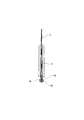
- the applicator of the present embodiment includes a shaft cylinder 1 provided with a coating liquid storage section 2, a hair tip 3 provided on the distal end side of the shaft cylinder 1, and the coating liquid storage section 2.
- a coating liquid guiding member 4 for guiding the coating liquid from the side toward the hair tip 3 is provided.
- the shaft cylinder 1 is formed in a substantially cylindrical shape as a whole, and the outer peripheral surface 5 on the tip end portion 1a side of the shaft tube 1 is formed in a tapered shape as shown in FIG.
- the inner peripheral surface of the portion 6 is formed so as to be in contact with the outer peripheral surface of the coating liquid guiding member 4.
- the coating liquid guiding member 4 is formed in a substantially cylindrical shape as a whole.
- the coating liquid guiding member 4 is formed with an insertion hole 13 into which the hair tip 3 can be inserted.
- the insertion hole 13 is formed as a through hole that penetrates from the opening 13 a on the front end side of the coating liquid guiding member 4 toward the opening 13 b on the rear end side.
- tip part 3a of the hair tip 3 protrudes from the opening part 13a of the front-end
- the hair tips 3 are inserted into the insertion holes 13 so as to protrude slightly from the opening 13b on the rear end side.
- the insertion hole 13 of the coating liquid guiding member 4 is formed in a tapered shape whose inner peripheral surface is narrower from the opening 13b on the rear end side of the coating liquid guiding member 4 toward the opening 13a on the front end side. ing. Further, the fibers constituting the hair tips 3 are formed in a tapered shape so that the coating liquid guiding member 4 and the hair tips 3 are in close contact with each other at the time of insertion. After the bristles 3 are inserted into the insertion holes 13 of the coating liquid guiding member 4, the bristles 3 are slightly pressed against the inner peripheral surface of the insertion holes 13 due to the restoring force of the bristles 3.
- the rear end portion 4b side of the coating liquid guiding member 4 is exposed to the coating liquid storage section 2 in the shaft tube 1, and the coating liquid guiding member 4 is in contact with the coating liquid 10 in the coating liquid storage section 2. ing. Further, the coating liquid guiding member 4 of the shaft tube 1 is arranged so that the tip portion 4 a side of the coating solution guiding member 4 protrudes to the outside of the shaft tube 1 with the bristles 3 inserted into the insertion holes 13. It is inserted in the front-end
- the coating liquid guiding member 4 is made of a sintered resin, more specifically, a sintered polyethylene having a porosity of about 30% or more in this embodiment.
- a sintered resin those having a pore diameter of 20 to 80 ⁇ m can be used, but those having 20 to 50 ⁇ m are more preferable, and those having 20 to 30 ⁇ m are more preferable.
- a small hole 8 is formed on the rear end portion 1 b side of the shaft cylinder 1, and air flows into a part of the rear portion side of the coating liquid reservoir 2 through the small hole 8, so that the coating liquid reservoir 2 is applied.
- the back pressure of the liquid 10 is adjusted.
- tip part 3a of the hair tip 3 is made to contact toward the application medium 21 (for example, paper etc. in the case of a writing instrument),
- the coating liquid is applied to the coating medium 21.
- the coating liquid 10 stored in the coating liquid storage unit 2 is in contact with the coating liquid guiding member 4 and the coating liquid guiding member 4 is in contact with the hair tip 3, the coating liquid is Then, it is guided from the coating liquid guiding member 4 to the hair tip 3 and applied to the coating medium 21 from the hair tip 3.
- the coating liquid guiding member 4 is made of a sintered resin, which is a porous material, and the insertion hole 13 of the coating liquid guiding member 4 is located behind the opening 13a on the front end side. Since it is formed so as to penetrate to the opening 13b on the end side, the coating liquid is applied in the state where the rear end 4b of the coating liquid guiding member 4 is in contact with the coating liquid in the coating liquid storage section 2.
- the sintered resin that is suitably absorbed by the guide member 4 and that constitutes the coating liquid guiding member 4 from the rear end portion 4b side of the coating liquid guiding member 4 toward the front end portion 4a side of the coating liquid guiding member 4 It will move in the pores.
- the coating liquid moves through the pores of the sintered resin constituting the coating liquid guiding member 4, so that the coating liquid flows from the rear end portion 4 b side to the front end portion 4 a side by the capillary phenomenon. Will be directed towards.
- the inner peripheral surface of the insertion hole 13 of the coating liquid guiding member 4 is formed in a tapered shape having a narrow width toward the distal end side, and the fibers constituting the hair tip are formed in a tapered shape so that the coating liquid is guided. Since the member 4 and the hair tip 3 are in close contact with each other, the coating liquid guided by the coating liquid guiding member 4 is preferably guided from the coating liquid guiding member 4 to the outer peripheral surface side of the hair tip 3. In other words, the induced coating liquid is surely supplied from the coating liquid guiding member 4 side to the hair tip 3 side, and is applied to the coating medium in a good state.
- the coating liquid guiding member 4 is made of sintered resin, and the inner peripheral surface of the insertion hole 13 of the coating liquid guiding member 4 is opened from the rear end side opening 13b to the front end side opening. From the coating liquid guiding member 4 located on the peripheral side of the hair tip 3, it is formed in a narrow taper shape toward 13 a and can be brought into close contact with the tapered fiber forming the hair tip.
- the coating liquid can be suitably supplied to the hair tip 3.
- the hair tip 3 is inserted into the insertion hole so that the rear end portion 3b of the hair tip 3 slightly protrudes from the opening 13b on the rear end side of the coating liquid guiding member 4 as described above. 13, the rear end 3 b of the hair tip 3 is also in contact with the coating solution in the coating solution reservoir 2, and therefore the tip 3 a from the rear end 3 b side of the hair tip 3. Also toward the side, the coating liquid is guided, and the coating liquid more reliably impregnates the hair tips 3.
- the inner peripheral surface of the insertion hole 13 of the coating liquid guiding member 4 is formed in a tapered shape with a narrow width toward the distal end side, and the fibers constituting the hair tips are tapered. Since the coating liquid guiding member 4 and the hair tip 3 are in close contact with each other, the coating liquid guiding member 4 and the hair tip 3 are integrated with each other. Since it is comprised by the sintered resin which has flexibility, the coating liquid guide member 4 will also bend suitably suitably, as the front-end
- the tip 3 and the coating liquid guiding member 4 can be integrated to provide an applicator.
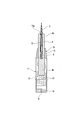
- This embodiment is one embodiment of a means for fixing the hair tip 3 to the coating liquid guiding member 4.
- a stopper 16 is formed on the rear end 3 b side of the hair tip 3.
- the stopper 16 of this embodiment is formed in a bowl shape as shown in FIG.
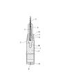
- This embodiment is another embodiment of the means for fixing the hair tip 3 to the coating liquid guiding member 4.
- the stopper 16 is formed, for example, by thermally melting the rear end portion 3b side of the hair tip 3, or by impregnating the rear end portion 3b side of the hair tip 3 with an adhesive.
- the shape of the stopper 16 is not a bowl shape as in the third embodiment, but is formed in a substantially spherical shape as shown in FIG. 6, but the shape is not limited.
- the stopper 17 on the side of the rear end 3b of the hair tip 3 can suitably prevent the hair tip 3 from coming out of the coating liquid guiding member 4.
- the outer peripheral surface 5 on the distal end portion 1 a side of the shaft tube 1 is formed in a gently tapered surface. This is different from the first embodiment in which the outer peripheral surface 5 is formed straight.
- the inner peripheral surface 6 on the distal end portion 1a side of the shaft tube 1 is formed so as to be in contact with the outer peripheral surface of the coating liquid guiding member 4.
- the coating liquid guiding member 4 protrudes into the coating liquid storage part 2 so that not only the rear end portion 4b of the coating liquid guiding member 4 but also the side surface of the coating liquid guiding member 4 is in contact with the coating liquid. Yes.
- the insertion hole 13 is formed in a concave shape having an opening 13a only on the distal end side, and the insertion hole 13 is formed to penetrate therethrough. This is different from the first and second embodiments.
- the hair tip 3 is fitted into the concave insertion hole 13.
- the coating liquid 10 stored in the coating liquid storage section 2 is in contact with not only the rear end portion 4b of the coating liquid guiding member 4 but also the side surface of the coating liquid guiding member 4. Since the coating liquid guiding member 4 is made of a sintered resin and other configurations are the same as those in the second embodiment, detailed description thereof is omitted.
- the hair tip 3 since the hair tip 3 is inserted into the concave insertion hole 13, the hair tip 3 is not directly in contact with the coating solution, but the hair tip 3 is inserted into the insertion hole 13.
- the coating liquid guide member 4 is made of sintered resin, and the coating liquid 10 stored in the coating liquid storage section 2 is not only the rear end portion 4 b of the coating liquid guide member 4 but also the side surface of the coating liquid guide member 4. Therefore, the coating liquid is suitably impregnated in the coating liquid guiding member 4. And since the hair tip 3 is inserted in the insertion hole 13 of the coating liquid guiding member 4 and the coating liquid guiding member 4 is in contact with the hair tip 3, the coating liquid is fed from the coating liquid guiding member 4 to the hair tip 3. It will be guided to.
- the inner peripheral surface of the insertion hole 13 of the coating liquid guiding member 4 is formed in a tapered shape with a narrow width toward the distal end side, and the fibers constituting the hair tip are formed in a tapered shape. Since the liquid guiding member 4 and the hair tip 3 are in close contact with each other, the coating liquid guided by the coating liquid guiding member 4 is preferably guided from the coating liquid guiding member 4 to the outer peripheral surface side of the hair tip 3. Thus, the induced coating liquid is reliably supplied from the coating liquid guiding member 4 side to the hair tip 3 side, and is applied to the coating medium in a good state.
- the coating liquid guiding member 4 is made of sintered resin, and the inner peripheral surface of the insertion hole 13 of the coating liquid guiding member 4 is formed in a narrow taper shape toward the tip side.
- the coating solution is suitably supplied to the hair tips 3 from the coating solution guiding member 4 located on the peripheral side of the hair tips 3. Will be able to.
- this embodiment demonstrated the case where the coating liquid induction
- the coating liquid is impregnated into the filling 9 composed of the aggregate of fibers, and the coating liquid guiding member 4 is inserted into the filling 9 by inserting the rear end portion 4 b of the coating liquid guiding member 4. Is in contact with the coating solution.
- the rear end portion 4 b of the coating liquid guiding member 4 is formed to be thinner than the body portion so that it can be easily inserted into the batting 9.
- Examples of the material of the batting 9 include natural fibers, polyacetal resins, acrylic resins, polyester resins, polyamide resins, polyurethane resins, polyolefin resins, polyvinyl resins, polyether resins, polyphenylene resins, and the like. A bundle of fibers made of or sponge or the like is used.
- the applicator comprises a shaft cylinder 1 having a coating liquid reservoir 2, a hair tip 3, and a coating liquid guiding member 4, and the outer peripheral surface 5 on the tip 1a side of the shaft cylinder 1 is gentle.
- the point made of sintered resin, the concave insertion hole 13 is formed in the coating liquid guiding member 4, the hair tip 3 is fitted in the insertion hole 13, and the entire coating liquid guiding member 4 is
- the point which is formed in a substantially cylindrical shape, the point that the small hole 8 is formed on the rear end 1b side of the shaft tube 1, and the like are the same as in the fifth embodiment.
- the coating liquid guiding member 4 is not in direct contact with the coating liquid as in the first, second, and fifth embodiments, but the coating liquid guiding member 4 is applied to the batting 9 impregnated with the coating liquid. Since the coating liquid guiding member 4 is brought into contact with the batting 9 by inserting the rear end portion 4b, the coating liquid impregnated in the batting 9 is guided to the coating liquid guiding member 4, and further from the coating liquid guiding member 4 It will be guided to the hair tip 3.
- the hair tip 3 is fitted into the concave insertion hole 13 of the coating liquid guiding member 4 in the same manner as in the fifth embodiment, and the inside of the insertion hole 13 of the coating liquid guiding member 4 is
- the peripheral surface is formed in a narrow taper shape toward the distal end side, and the fibers constituting the hair tip are formed in a taper shape so that the coating liquid guiding member 4 and the hair tip 3 are in close contact with each other. Therefore, the coating liquid impregnated and held in the coating liquid guiding member 4 is supplied to the hair tip 3 from the peripheral portion side of the hair tip 3, and reliably from the coating liquid guiding member 4 side to the hair tip 3 side. It will be supplied to.
- this embodiment demonstrated the case where the coating liquid induction
- the outer peripheral surface of the coating liquid guiding member 4 is formed in a gently tapered surface, and this coating liquid guiding member 4 is located on the tip portion 1 a side of the shaft tube 1. Attached to the opening 11. That is, in the present embodiment, the tip 1a of the shaft cylinder 1 has a predetermined thickness as in the first embodiment, and the coating liquid guiding member 4 is inserted into the inner peripheral surface 6 of the shaft cylinder 1 so that the shaft cylinder 1 is inserted.
- the coating liquid guiding member 4 is attached to the opening 11 of the shaft cylinder 1 formed in a thin cylindrical shape of the same degree as a whole, instead of holding the coating liquid guiding member 4 at the tip 1a of the
- the coating liquid guiding member 4 itself is configured to form the tip of the shaft tube 1.
- the insertion hole 13 penetrated in the same manner as in the first and second embodiments is formed in the coating liquid guiding member 4 instead of the concave insertion hole 13 as in the fifth and sixth embodiments.
- the hair tips 3 are inserted into the insertion holes 13.
- the rear end portion 3 b of the hair tip 3 protrudes into the coating liquid storage portion 2 and is in contact with the coating solution 10.
- the rear end side of the coating liquid guiding member 4 is also in contact with the coating liquid 10.
- the coating film 12 made of a synthetic resin film is applied to the outer peripheral surfaces of the coating liquid guiding member 4 and the shaft tube 1.
- the coating liquid guiding member 4 is impregnated with the coating liquid and adheres to the hand. This is to prevent this.
- the coating 12 is applied across the shaft tube 1 from the coating liquid guiding member 4, but it can be applied only to the coating liquid guiding member 4, and the coating liquid guiding member If it adheres to 4, the objective of preventing that a coating liquid adheres to a hand will be achieved once.
- the applicator includes a shaft tube 1 having a coating liquid reservoir 2, a hair tip 3, and a coating liquid guide member 4, and the coating liquid guide member 4 is formed of a sintered resin.
- the point that a small hole 8 is formed on the rear end 1b side of the shaft tube 1 is the same as in the first, fifth, sixth, etc.
- the coating liquid guiding member 4 is in contact with the coating liquid, but also the hair tips 3 themselves are in contact with the coating liquid. Therefore, in this embodiment, not only the coating liquid is guided to the hair tip 3 from the coating liquid guiding member 4 side, but also the coating solution is directly guided to the hair tip 3.
- the coating liquid is supplied from the outer peripheral surface side of the hair tip 3 to the hair tip 3 and reliably from the coating liquid guiding member 4 side to the hair tip 3 side. Will be supplied.
- the coating liquid reservoir 2 is not provided in the shaft tube 1, and the hair tip 3 is directly immersed in a separately prepared coating solution, and the coating solution impregnated in the hair tip 3 in this way. Will be applied to the application medium.
- the coating liquid guiding member 4 has an insertion hole 13, and the inner peripheral surface of the insertion hole 13 is formed in a tapered shape that is narrower toward the distal end side.
- the hair tip 3 in which the fiber was formed in the insertion hole 13 is inserted into the insertion hole 13, and the hair tip 3 is inserted in a state of being in close contact with the inner peripheral surface of the insertion hole 13 of the coating liquid guiding member 4,
- the coating liquid impregnated in the hair tip 3 is also impregnated in the coating liquid guiding member 4.
- the coating liquid guiding member 4 is brought into contact with the coating liquid 10 or the batting 9 in the coating liquid reservoir 2 so that the coating liquid is self-contained. It is different from the applicator. Moreover, since the coating liquid storage part 2 does not exist, in this embodiment, the shaft cylinder 1 is made into a solid shape, which is different from the above-described embodiments in which the shaft cylinder 1 is formed in a hollow shape.
- a recess 14 is formed at the tip 1 a of the solid shaft tube 1, and the coating liquid guiding member 4 is fitted and attached in the recess 14. Further, a recess 15 having a smaller diameter than the recess 14 is formed in communication with the recess 14. The hair tips 3 are fitted and attached in the small-diameter recesses 15.
- the coating liquid guiding member 4 a material composed of sintered resin or a material composed of synthetic fibers bonded with a binder can be used.
- the applicator of the present embodiment is not a coating liquid self-contained applicator as described above, the hair tip 3 is directly immersed in a separately prepared coating liquid and applied to a coating medium.
- the insertion hole 13 is formed in the coating liquid guiding member 4 as described above, and the hair tip 3 is inserted into the insertion hole 13 so that the inside of the insertion hole 13 of the coating liquid guiding member 4 in the hair tip 3 is inserted. Since it is in close contact with the peripheral surface, the coating liquid impregnated in the bristles 3 is also impregnated in the coating liquid guiding member 4 and is held for a certain period of time.
- the coating liquid held by the coating liquid guiding member 4 is guided from the coating liquid guiding member 4 side to the hair tip 3 side, and the coating liquid thus guided is also applied by the hair tip 3. It will be applied to the medium.
- the insertion hole 13 is formed in the coating liquid guiding member 4 as in the above embodiments, and the inner peripheral surface of the insertion hole 13 is formed in a tapered shape that is narrower toward the distal end side. .
- the hair tip 3 in which the fiber was formed in the taper shape is inserted in the insertion hole 13, and the hair tip 3 is inserted in a state of being in close contact with the inner peripheral surface of the insertion hole 13 of the coating liquid guiding member 4. Yes.
- the coating liquid is impregnated by directly contacting the hair tip 3 with the coating liquid, and the coating liquid guided from the hair tip 3 side to the coating liquid guiding member 4 side is applied to the coating liquid guiding member 4.
- the coating liquid is guided from the coating liquid guiding member 4 side to the hair tip 3 side, so that it is applied to the coating medium in a better state than a general direct liquid type coating. Can do.
- an adapter 18 called a front shaft is press-fitted and attached to the distal end side of the shaft tube 1.
- the distal end side of the adapter 18 is formed in a tapered shape, and the distal end side of the coating liquid guiding member 4 is also formed in a tapered shape.
- the hair tips 3 are inserted into the insertion holes 13 formed in the coating liquid guiding member 4 as in the eighth embodiment.
- a support 19 made of synthetic resin is attached, and a rear end 3 b of the hair tip 3 is attached in a recess 20 formed on the front end side of the support 19.
- the hair tip 3 is not in direct contact with the coating liquid 10, and only the coating liquid guiding member 4 is in contact with the coating liquid 10 as in the first embodiment and the like.
- the coating liquid impregnated and held in the member 4 is supplied to the hair tip 3 from the outer peripheral surface side of the hair tip 3.
- the material of the coating liquid guiding member 4 is not limited to the synthetic resin molded body, the sintered resin such as sintered polyethylene, and the synthetic fiber bonded with the binder in the above embodiment. It can also be composed of a synthetic resin, and further can be composed of other materials such as ceramic foam, foam metal, sintered metal porous body, and the like. In short, it is only necessary to be made of a material that can be impregnated with the coating liquid and can guide the coating liquid to the hair tip 3 side.
- the material of the hair tips 3 is not limited to polyester fibers such as polyethylene terephthalate and polybutylene terephthalate of the above embodiment, polyamide fibers, etc., and can be composed of other synthetic fibers, It is also possible to use natural fibers, and the material of the bristles 3 does not matter.
- the material of the batting 9 is also natural fiber, polyacetal resin, acrylic resin, polyester resin, polyamide resin, polyurethane resin, polyolefin resin, polyvinyl resin, PP resin, polyether resin of the above embodiment. It is not limited to a bundle of fibers made of resin, polyphenylene resin, or the like, or a sponge, and other materials can be used.
- the application of the applicator is not limited to a writing instrument, but can also be used for a cosmetic tool.
Landscapes
- Pens And Brushes (AREA)
- Coating Apparatus (AREA)
Abstract
筆ペン等の筆記具、或いは化粧用具等、インクや化粧液等の塗布液を塗布するための塗布具に関し、毛先の割れを生じるおそれがなく、且つ毛先の部分への塗布液の誘導を確実に行うことができ、塗布液を良好な状態で塗布することができる塗布具を提供することを課題とする。また、塗布液を含浸可能で、該塗布液を塗布媒体に塗布可能な毛先を有する塗布具において、前記毛先側へ塗布液を誘導することができる塗布液誘導部材4が具備されていることを特徴とする。
Description
本発明は、筆ペン等の筆記具、或いは化粧用具等、インクや化粧液等の塗布液を塗布するための塗布具に関する。
周知のように、筆ペン等の筆記具、化粧用具等、インクや化粧液等の塗布液を塗布媒体に塗布する塗布具として、従来から種々のものが用いられている。筆記具においては、紙が塗布媒体とされ、化粧用具においては、顔の目の周辺部等が塗布媒体となる。このような塗布具のうち、古来から使用されているものとして筆があり、筆はその筆先に墨を付着させるという作業を要する点で、一見原始的な筆記具であるが、筆記具に必要な特性が十分に考慮されている。たとえば書道において、「止め」という静的な状態と、「はね」や「曲がり」という動的な状態とのいずれにおいても、筆の本体の動きに毛先がよく追従していくこと、或いは付着された墨が毛先の根元部から先端部側へ良好に供給されること等は、筆記具に必要な特性が筆に具備されていることの好適な例である。
良い筆の条件として、穂先が鋭いこと、毛の一本一本が素直でよく揃っていること、毛先がふっくらしていること、弾性に富むこと等が挙げられ、また「毛腰が適度に柔らかく、墨の含みがよい。」等が良い筆の条件とされている。ここで「毛腰」とは、手の動きを筆先へ伝える操作性のことであり、「含み」とは、墨の先端側への伝達性のことである。毛腰が適度に柔らかい筆では、毛先が鋭く、筆を運ぶ途中で毛先がばらけず、弾性に富む等の特性がある。また、「含み」の良い筆は、供給源として、持続的に墨を供給することができる伝達性、調節性が良好である等の特性がある。一般の筆は、墨を毛先の根元部分に貯留して「含み」の機能を奏しており、その毛先の根元部分は墨の補給部であると同時に、先端側への墨の急速な供給を行う機能も果たしている。
このような古来からの筆とは異なり、筆ペンの場合は、インクの貯留部のような液体の永続的な補給部を有するため、基本的には「含み」の機能を毛先で持たせる必要がない。しかし、筆ペンは、液補給部(インクの貯留部)が筆記部分である毛先から離れた位置に設けられているため、先端側へのインクの急速な補給を行う機能が不十分となるおそれがある。また筆ペンでは、古来からの筆のような書き味を実現させることができないので、毛先を構成する繊維の1本ずつにテーパを付けることも行われている。ところが、このようなテーパを付けることで、先端側へインクを供給する機能がさらに低下することも判明している。
一般に、繊維間への液浸透速度は、下記(1)のルーカス・ウオッシュバーンの式が用いられることが多い。下記(1)式において、Xは液体の到達距離、ηは液体の粘度、Dは繊維間に生じる流路の平均的な径、tは経過時間、γは液体の表面張力、θは液体と繊維との接触角である。

繊維にテーパがついていない場合には、(1)式でDが一定である。繊維にテーパがついている場合には、Dが到達距離に応じて変化する。先端部ではDが小さくなり、液体の伝達速度が遅くなる。つまり、繊維にテーパがついている場合は、毛先の先端側程、流路面積が減少し、液体の伝達量が急速に減少するが、このことを図12に基づいて説明する。図12は、縦軸に液体の浸透量Q、横軸に液体の移動距離Xを表したグラフであるが、繊維にテーパがついていない場合の曲線aに比べて、繊維にテーパがついた場合の曲線bは急激に液体の浸透量Qが低下していることが示されている。
この図12のグラフは、繊維間の毛細管力の駆動力とその流路に生じる流体抵抗による減速効果とのバランスを表現したものであり、繊維にテーパがついている場合はもちろんであるが、繊維にテーパがついていない場合であっても、筆ペンのように液の貯留部から毛先に向かってインクを供給する場合、液体流路長が長いので、古来からの筆のように、近くに液の供給源があるものと比べてインク供給の面で不利なことが示されている。また、上記(1)式によると、液体粘度ηが大きくなると、液体の移動距離が小さくなることが示され、インクの粘度が大きい場合、移動速度が十分にとれず、かすれ現象をひきおこすことがあり、また供給途中での沈着等を来すことがある。
そこで、このような問題点に鑑み、筆記部に近い部位へ液体(インク)を供給するために、インク貯留部から、中継芯と称されるインク誘導部分やパイプを毛先の中心部分に設けて毛先にインクを供給しうるように構成された筆ペンも開発されている。このような中継芯を備えた構造の筆ペンに関する特許出願として、たとえば下記特許文献1乃至3に示すような出願がなされている。このような中継芯を備えた構造の筆ペンは、供給機構が筆記部に近いため 急速なインクの供給にも追従できるものである。
しかし、このような中継芯は、軸筒内にインク貯留部と毛先とに跨がるように設けられるので、この中継芯を挿通させるための孔を毛先に穿設しなければならないこととなる。そのような孔を毛先に穿設する場合、毛先に割れを生じるおそれがあるという新たな問題点が発生した。また、毛先の中心部に誘導部材である中継芯を配置しているので、たとえば2mmΦ以下のような細い筆は作りにくいという問題がある。
本発明は、上記のような問題点を解決するためになされたもので、上記のような毛先の割れを生じるおそれがなく、毛先側への塗布液の誘導を確実に行うことができるとともに、その毛先の先端部側への液の供給も良好な状態で行うことができ、ひいては塗布液を良好な状態で塗布することができる塗布具を提供することを課題とする。また本発明の他の課題は、これらの機能を維持しつつ、毛先を細くすることを可能とすることである。
本発明は、このような課題を解決するためになされたもので、塗布液を含浸可能で、該塗布液を塗布媒体に塗布可能な毛先を有する塗布具において、前記毛先側へ塗布液を誘導することができる塗布液誘導部材が具備されていることを特徴とする塗布具を提供するものである。本発明の塗布具をかかる構成とすることで、塗布液は、その塗布液誘導部材によって毛先側へ塗布液を供給することができ、従って、従来の塗布具のように毛先の中心部に位置する中継芯を設けることが不要となり、その結果、このような中継芯を設けることによって生じるおそれがあった毛先の不用意な割れ等を確実に防止することができる。
また、塗布液誘導部材が毛先側へ塗布液を供給することができるように構成されているので、中継芯が設けられていた従来の構造のものに比べて、塗布液誘導部材と毛先との接触面積を大きくとることができ、また毛先への塗布液の移動距離も構造上短くすることができ、毛先の部分への塗布液の誘導を確実に行うことができ、塗布液の塗布が不良となることがない。
さらに、塗布液誘導部材が毛先側へ塗布液を供給することができるように構成されて、従来のような中継芯が不要となるので、毛先を従来に比べて細く形成することができる。この結果、たとえば従来の面相筆は毛先が細いので根元に貯留機能を持たせるために毛先を長くする必要があったが、本発明では、毛先が短く細い筆ペンのような筆記具を提供することが可能となる。
塗布液誘導部材には、好ましくは、毛先を挿入するための挿入孔が形成される。さらに、塗布液誘導部材には、好ましくは、挿入孔側へ毛細管現象によって塗布液を誘導しうるような塗布液誘導用孔が、前記挿入孔に連通して形成される。かかる構成とすることで、塗布液が、塗布液誘導部材の塗布液誘導用孔において毛細管現象によって誘導され、さらにその塗布液誘導用孔から挿入孔に誘導されることとなり、その結果、毛細管現象によって塗布液誘導用孔を誘導されてきた塗布液が、挿入孔内に挿入された毛先に含浸されることとなる。従って、塗布液誘導部材から毛先側への塗布液の誘導が確実に行われることとなる。
この塗布液誘導用孔は、たとえば、挿入孔を中心として該挿入孔から外側に向かって放射状に形成された複数の細孔によって構成される。かかる構成とすることで、毛細管現象をより好適に発揮させることが可能となる。
このような挿入孔に塗布液誘導用孔が連通して形成された塗布液誘導部材は、たとえば合成樹脂製成形体で構成される。合成樹脂製成形体で構成することで、塗布液誘導用孔が、毛細管現象を生じさせるような複雑な形状のものであっても、塗布液誘導部材の製造を容易に行うことができる。
塗布液誘導部材の挿入孔は、好ましくは、毛先の先端部を突出させる先端側の開口部と、該毛先の後端部が塗布液と接触しうるように開口して形成された後端側の開口部とに貫通して形成される。また、毛先の後端部側には、好ましくは、塗布液誘導部材の後端面側に係止可能となるように、該塗布液誘導部材の後端部側の開口部より幅広なストッパーが形成される。かかる構成とすることで、挿入孔からの毛先の抜け出しを好適に防止することができる。
毛先は、好ましくは、テーパ状繊維が多数本束ねられて構成される。また、塗布液誘導部材の挿入孔の内周面は、先端側に向かって幅狭なテーパ状に形成される。かかる構成とすることで、テーパ状繊維が多数本束ねられて構成された毛先が塗布液誘導部材の挿入孔内に挿入された際、その毛先は塗布液誘導部材内に密着状態で挿入されることとなり、従って、塗布液誘導部材側から毛先側への塗布液の誘導が非常に良好な状態で行われることとなる。
また、塗布液誘導部材の挿入孔が、該挿入孔の後端部側から先端部側に向かって幅狭なテーパ状に形成されている場合には、その挿入孔の後端部側から先端部側に向かう方向においても、塗布液の誘導が良好な状態で行われ、その結果、毛先の先端部側への塗布液の供給が良好な状態で行われることとなる。さらに、塗布液誘導部材の挿入孔が後端部側から先端部側に向かって幅狭なテーパ状に形成され、テーパ状繊維が多数本束ねられて構成された毛先が挿入孔内に挿入された際に、毛先が塗布液誘導部材内に密着状態で挿入される結果、毛先と塗布液誘導部材との間に隙間が生じるおそれもなく、その結果、毛先が塗布液誘導部材に確実に固定されることとなる。また、毛先が塗布液誘導部材内に密着状態で挿入されることで、先の尖った安定した毛先が得られることとなる。さらに、毛先が塗布液誘導部材内に密着状態で挿入されることにより、毛先と塗布液誘導部材とはあたかも一体化されたような状態となり、その結果、塗布媒体に接触させる際等の塗布具の操作性が向上する。
塗布液誘導部材は、好ましくは多孔質材料で構成される。かかる構成とすることで、塗布液は多孔質材料で構成された塗布液誘導部材に吸収され、その塗布液誘導部材によって周辺部側から毛先に塗布液が供給される作用が、よりスムーズに生じることとなる。塗布液誘導部材を多孔質材料で構成する場合、その孔径は、好ましくは20~80μmとされる。多孔質材料としては、焼結樹脂、発泡性合成樹脂、セラミックの発泡体、発泡金属、焼結金属多孔質体等が例示されるが、とりわけ焼結樹脂で構成されることが望ましい。
塗布液誘導部材は、好ましくは、可撓性を有して構成される。かかる構成とすることで、たとえば紙等の塗布媒体に毛先が接触して撓むとき、塗布液誘導部材も毛先と一体となって撓み易くなり、塗布具の操作性が一層向上する。
また、挿入孔は、上記のように貫通して形成される場合の他、後端側の開口部を有しない凹状のものとして形成することも可能である。毛先は、好ましくは、塗布液誘導部材4の挿入孔の内周面に面接触状態となるように挿入される。
以上のように。本発明によって、毛先の割れを生じるおそれがなく、毛先側への塗布液の誘導を確実に行うことができるとともに、その毛先の先端部側への液の供給も良好な状態で行うことができ、ひいては塗布液を良好な状態で塗布することができる塗布具を提供することが可能となる。
さらに、塗布液誘導部材が毛先側へ塗布液を供給することができるように構成されているので、その構造上からも毛先を従来に比べて細く形成することができ、たとえば面相筆のように毛先の長い形式の書き味の筆記具であって、実際の面相筆に比べて毛先が短く細い筆ペンのような筆記具を提供することが可能となる。
本発明の塗布具は、上述のように、塗布液を含浸可能で、該塗布液を塗布媒体に塗布可能な毛先を有する塗布具において、前記毛先側へ塗布液を誘導可能な塗布液誘導部材が具備された構成からなるものである。
毛先の材質は特に限定されるものではなく、たとえばポリエチレンテレフタレートやポリブチレンテレフタレート等のポリエステル繊維、ポリアミド繊維等の合成繊維が用いられる。毛先は、テーパ状繊維が多数本束ねられて構成されていることが望ましい。
また、塗布液誘導部材の材質も特に限定されるものではなく、たとえば合成繊維を集合させ、バインダーで結合させたもの、連続気泡を有する発泡性合成樹脂、多孔性射出成形樹脂、焼結樹脂等を用いることができる。さらに、セラミックの発泡体、発泡金属、焼結金属多孔質体等を使用することもできる。また、合成樹脂製の成形体のようなものを用いることもできる。ただし、焼結樹脂、多孔性射出成形樹脂、連続気泡を有する発泡性合成樹脂、セラミックの発泡体、発泡金属、焼結金属多孔質体等の多孔質材料で構成されていることが望ましく、とりわけ、焼結樹脂、多孔性射出成形樹脂、連続気泡を有する発泡性合成樹脂等で構成されていることが望ましい。
焼結樹脂は、樹脂粉末(樹脂微粒子)を焼結させて成形することができ、上記のように、塗布液誘導部材の挿入孔を、先端側に向かって幅狭なテーパ状となるような形状に、容易に成形することができる。また、塗布液誘導部材が可撓性を有するように形成する上でも好都合である。さらに、塗布液を塗布液誘導部材側から毛先側へ誘導する作用、及び塗布液を塗布液誘導部材の後端部側から先端部側へ供給する作用にも優れている。焼結樹脂としては、ポリエチレン、ポリプロピレン、ポリテトラフルオロエチレン、ポリアミド、ポリアセタール等の熱可塑性樹脂や、フェノール樹脂等の熱硬化性樹脂を用いることができる。これらの中でも、ポリエチレンを好適に使用することができる。ポリエチレンとしては、超高分子量ポリエチレン、高密度ポリエチレン、低密度ポリエチレン等を用いることができる。
また焼結樹脂は、上述のように、樹脂粉末(樹脂微粒子)を焼結させて製造されるものであるが、その際の樹脂微粒子の粒子径としては、1~100μmのものを使用するのが望ましく、5~30μmのものを使用するのがより望ましい。また、焼結樹脂の場合の気孔率は、20~50%程度のものを使用するのが望ましく、30~50%程度のものを使用するのがより望ましい。さらに、加熱時の温度は各樹脂の融点に応じて設定され、加熱時間は、たとえば10分~3時間等の任意の時間とすることができる。
また、塗布液誘導部材を多孔質材料で構成する場合、その多孔質材料の孔径は、20~80μmとすることが望ましい。通常の顔料は一次粒径が20~100nm、分散粒径が0.06~6μm程度であり、またラメの一種パールでは 数μm近くのものもあり、これら種々のインクを色の変化を起こさずに塗布液誘導部材で供給するために、その塗布液誘導部材を構成する多孔性樹脂の平均孔径は20μm~80μm程度があることが望ましいのである。
さらに、塗布液誘導部材は、好ましくは可撓性を有して構成される。
さらに、塗布液誘導部材への毛先の取り付けは、たとえば塗布液誘導部材に挿入孔を形成し、その挿入孔に毛先を挿入することによって行う。塗布液誘導部材の挿入孔は、たとえば、毛先を突出させる先端側の開口部と、毛先が塗布液と接触しうるように開口して形成された後端側の開口部とに貫通して形成された挿入孔のような形態とされる。或いは、このような挿入孔の他に、後端側の開口部を有しない凹状のものとして形成することも可能である。
これらの場合において、毛先は、塗布液誘導部材の挿入孔の内周面に面接触状態となるように挿入されるのが望ましい。このように面接触状態となることによって、塗布液誘導部材に含浸、保持された塗布液は、面接触状態とされた毛先の周辺部側から、毛先に供給されることとなる。
さらに、塗布液誘導部材の挿入孔の内周面は、先端側に向かって幅狭なテーパ状に形成することが可能である。このように塗布液誘導部材の挿入孔の内周面をテーパ状に形成し、さらにテーパ状繊維を多数本束ねて毛先を構成することで、塗布液誘導部材の挿入孔の内周面と、毛先との密着性がより良好となる。このように密着状態で毛先が塗布液誘導部材の挿入孔に挿入されることによって、塗布液誘導部材に含浸、保持された塗布液は、毛先の周辺部側から、好適に毛先に供給されることとなるのである。
さらに、塗布液誘導部材には、挿入孔側へ毛細管現象によって塗布液を誘導しうるような塗布液誘導用孔を、前記挿入孔に連通して形成することができる。このような塗布液誘導用孔を形成することにより、塗布液は、塗布液誘導部材の塗布液誘導用孔を毛細管現象によって誘導され、さらにその塗布液誘導用孔から挿入孔に誘導されることとなり、その結果、毛細管現象によって塗布液誘導用孔を誘導されてきた塗布液が、挿入孔内に差し込まれた毛先に含浸されることとなる。このような塗布液誘導用孔は、たとえば、挿入孔を中心として該挿入孔から外側に向かって放射状に形成された複数の細孔によって構成される。このように、塗布液誘導部材の挿入孔に塗布液誘導用孔が連通して形成される場合には、成形を容易に行う観点から、塗布液誘導部材は、上記のような多孔質材料ではなく、合成樹脂製成形体で構成されることが望ましい。この場合の合成樹脂としては、たとえばポリアセタール樹脂、フッ素系樹脂、アクリル系樹脂、ポリプロピレン等のポリオレフィン系樹脂を用いることができ、またポリブチレンサクシネート(PBS)のような生分解性合成樹脂を用いることも可能である。
さらに、挿入孔の断面形状は、たとえば楕円形、矩形、多角形、星型等とすることができる。また、挿入孔の先端側(入口部)と後端側(出口部)とで異なる断面形状とすることも可能である。たとえば、入り口が真円、出口が楕円となるような場合である。
また、毛先の後端部側には、たとえば、塗布液誘導部材の後端部側に係止可能となるように、該塗布液誘導部材の後端部側の開口部より幅広なストッパーを形成することも可能である。このストッパーとしては、たとえば鍔状に突出させて形成したもの、或いは毛先の後端部側を熱融解することによって形成したもの、さらには、毛先の後端部側に接着剤を含浸させることによって形成したもの等が用いられる。
さらに、塗布具の本体部分は、たとえば塗布液を貯留する塗布液貯留部を軸筒内に設けたような構成とすることが可能である。
さらに、上記のような塗布液誘導部材の構造を利用して、細い筆の根元を塗布液誘導部材で包囲し、「含み」機能を持たせれば、毛先を長くしなくてもよく、使いやすい極細筆を提供することができる。実際の試作では1mmΦ×4mm程度の筆を製作することが可能となった。これは従来の極細筆の半分の長さである。細筆を使い慣れない者でも十分に使いこなせるという利点がある。
以下に、本発明の塗布具のより具体的な構成を説明する。
(実施形態1)
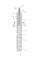
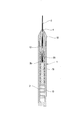
本実施形態の塗布具は、図1に示すように、塗布液貯留部2を備えた軸筒1と、該軸筒1の先端側に設けられた毛先3と、前記塗布液貯留部2側から前記毛先3側に塗布液を誘導する塗布液誘導部材4とを具備して構成されている。
本実施形態の塗布具は、図1に示すように、塗布液貯留部2を備えた軸筒1と、該軸筒1の先端側に設けられた毛先3と、前記塗布液貯留部2側から前記毛先3側に塗布液を誘導する塗布液誘導部材4とを具備して構成されている。
軸筒1は、その全体が略円柱状に形成され、該軸筒1の先端部1a側の内周面6は、塗布液誘導部材4の外周面と接触しうるように形成されている。また、塗布液誘導部材4は全体が略円柱状に形成されている。
塗布液誘導部材4には、前記毛先3を挿入可能な挿入孔13が形成されている。この挿入孔13は、図1に示すように、塗布液誘導部材4の先端側の開口部13aから後端側の開口部13bに向かって貫通するような貫通孔として形成されている。このような貫通孔とされることで、毛先3の先端部3aが前記塗布液誘導部材4の先端側の開口部13aから突出し、毛先3の後端部3bが塗布液誘導部材4の後端側の開口部13bとほぼ同面上に位置するように、毛先3が挿入孔13に挿入されている。
塗布液誘導部材4の後端部4b側は、軸筒1内の塗布液貯留部2に臨出され、塗布液貯留部2内の塗布液10に塗布液誘導部材4が接触した状態とされている。また塗布液誘導部材4の先端部4a側は、挿入孔13内に毛先3を挿入させた状態で軸筒1の外部に突出されるように、前記塗布液誘導部材4が軸筒1の先端部1a側に挿入されている。
さらに、塗布液誘導部材4は、本実施形態では、合成樹脂を成形した合成樹脂成形体によって構成されている。合成樹脂としては、たとえばフッ素系樹脂、アクリル系樹脂、ポリアセタール樹脂、ポリプロピレン等のポリオレフィン系樹脂、ポリブチレンサクシネート(PBS)のような生分解性合成樹脂、その他の種々の合成樹脂を使用することができる。
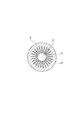
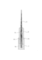
さらに、本実施形態では、図2に示すように、断面円形の挿入孔13の周囲に連通して塗布液誘導用孔17が形成されている。この塗布液誘導用孔17は、塗布液を挿入孔13側へ毛細管現象によって誘導するためのもので、前記挿入孔13を中心として該挿入孔13から外側に向かって放射状に形成された複数のスリット状の細孔によって構成されている。そして、挿入孔13及び塗布液誘導用孔17は、塗布液誘導部材4の先端側の開口部13aから後端側の開口部13bにかけて連続的に形成され、その連続的に形成された挿入孔13及び塗布液誘導用孔17は、先端側の開口部13aから後端側の開口部13bに至る塗布液誘導部材4のすべての断面において同一形状に形成されている。
軸筒1の後端部1b側には小孔8が穿設され、その小孔8によって塗布液貯留部2の後部側の一部に空気が流入されて、該塗布液貯留部2の塗布液10の背圧が調整されることとなる。
そして、このような構成からなる塗布具を使用する場合には、毛先3を塗布媒体(たとえば筆記具の場合は紙等)に向けて接触させ、塗布液を塗布媒体に塗布する。この場合において、塗布液貯留部2に貯留されている塗布液10は、塗布液誘導部材4と接触しており、その塗布液誘導部材4が毛先3に接触しているので、塗布液は、塗布液誘導部材4から毛先3に誘導されて毛先3から塗布媒体に塗布されることとなる。
この点をより詳細に説明すると、塗布液誘導部材4の挿入孔13の周囲に、上記のように塗布液を挿入孔13側へ毛細管現象によって誘導するための塗布液誘導用孔17が前記挿入孔13に連通して形成されており、また、このような挿入孔13及び塗布液誘導用孔17は、先端側の開口部13aから後端側の開口部13bに至る塗布液誘導部材4のすべての断面において同一形状に形成されているため、塗布液誘導部材4の後端部4bが、塗布液貯留部2内の塗布液と接触している状態において、塗布液は、前記塗布液誘導部材4の後端部4bにおける塗布液誘導用孔17の部分から、該塗布液誘導部材4の先端部4a側に向かって、毛細管現象によって、連続的に形成された塗布液誘導用孔17内を移動することになる。
このように、塗布液は、毛細管現象によって、塗布液誘導部材4の後端部4b側から先端部4a側に向かって塗布液誘導用孔17内で誘導され、さらに塗布液誘導用孔17に連通する挿入孔13側へ誘導されることになる。
この結果、塗布液は、挿入孔13内に挿入された毛先3の外側である塗布液誘導用孔17の部分から、その毛先3の外周面側に誘導されることとなり、誘導された塗布液は、塗布液誘導部材4側から毛先3側に確実に供給されることとなり、塗布媒体に良好な状態で塗布されることとなる。
このように、本実施形態では、塗布液誘導部材4に、毛先3が挿入される挿入孔13に連通して、塗布液を毛細管現象によって誘導する塗布液誘導用孔17を形成したので、毛先3の周辺部側に位置する塗布液誘導用孔17から、塗布液を毛先3に供給することができ、従って、従来の塗布具に設けられていた中継芯のように、毛先3のほぼ中心部分に装填するような取り付けが不要となり、その結果、毛先3の割れなどを生じさせるようなことがないのである。
尚、本実施形態においては、毛先3の後端部3bが、上記のように、塗布液誘導部材4の後端側の開口部13bとほぼ同面上に位置するように、毛先3が挿入孔13に挿入されているので、その毛先3の後端部3bも塗布液貯留部2内の塗布液と接触した状態となっており、従って毛先3の後端部3b側から先端部3a側に向かっても、塗布液が誘導されることとなり、塗布液がより確実に毛先3に含浸することとなる。
また筆のような形態の塗布具では、キャップなしで一定時間開放すると、外側の部分から塗布液が蒸発して濃縮され、その結果、塗布液が固まるという問題点があるが、本実施形態においては、毛先3が塗布液誘導部材4の挿入孔13に挿入され、塗布液誘導部材4側から塗布液が毛先3に供給されるように構成されているので、毛先の外側は塗布液の供給には関与しないこととなり、従って、毛先の外側の部分から塗布液が蒸発して濃縮され、塗布液が固まるという現象は、本実施形態においては、塗布液誘導部材4よりわずかに突出した毛先の部分においてしか発生しない。従って、筆記できる状態に回復するには、この塗布液誘導部材4よりわずかに突出した毛先の部分を塗布媒体に押し付けるわずかの動作で完了することとなる。
また筆のような形態の塗布具では、キャップなしで一定時間開放すると、外側の部分から塗布液が蒸発して濃縮され、その結果、塗布液が固まるという問題点があるが、本実施形態においては、毛先3が塗布液誘導部材4の挿入孔13に挿入され、塗布液誘導部材4側から塗布液が毛先3に供給されるように構成されているので、毛先の外側は塗布液の供給には関与しないこととなり、従って、毛先の外側の部分から塗布液が蒸発して濃縮され、塗布液が固まるという現象は、本実施形態においては、塗布液誘導部材4よりわずかに突出した毛先の部分においてしか発生しない。従って、筆記できる状態に回復するには、この塗布液誘導部材4よりわずかに突出した毛先の部分を塗布媒体に押し付けるわずかの動作で完了することとなる。
(実施形態2)
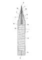
本実施形態の塗布具は、図3に示すように、塗布液貯留部2を備えた軸筒1と、該軸筒1の先端側に設けられた毛先3と、前記塗布液貯留部2側から前記毛先3側に塗布液を誘導する塗布液誘導部材4とを具備して構成されている。
本実施形態の塗布具は、図3に示すように、塗布液貯留部2を備えた軸筒1と、該軸筒1の先端側に設けられた毛先3と、前記塗布液貯留部2側から前記毛先3側に塗布液を誘導する塗布液誘導部材4とを具備して構成されている。
軸筒1は、その全体が略円柱状に形成され、該軸筒1の先端部1a側の外周面5は、図3に示すように先細なテーパ状に形成され、その先端部1aにおける開口部6の内周面が、塗布液誘導部材4の外周面と接触しうるように形成されている。また、塗布液誘導部材4は全体が略円柱状に形成されている。
塗布液誘導部材4には、前記毛先3を挿入可能な挿入孔13が形成されている。この挿入孔13は、図3に示すように、塗布液誘導部材4の先端側の開口部13aから後端側の開口部13bに向かって貫通するような貫通孔として形成されている。このような貫通孔とされることで、毛先3の先端部3aが前記塗布液誘導部材4の先端側の開口部13aから突出し、毛先3の後端部3bが塗布液誘導部材4の後端側の開口部13bよりもわずかに突出するように、毛先3が挿入孔13に挿入されている。また、この塗布液誘導部材4の挿入孔13は、その内周面が塗布液誘導部材4の後端側の開口部13bから先端側の開口部13aに向かって幅狭なテーパ状に形成されている。さらに、毛先3を構成する繊維は、挿入時において該塗布液誘導部材4と毛先3とが密着した状態となるように、テーパ状に形成されている。塗布液誘導部材4の挿入孔13への毛先3の挿入後には、毛先3の復元力によって、毛先3は挿入孔13の内周面にわずかに圧接された状態となる。
塗布液誘導部材4の後端部4b側は、軸筒1内の塗布液貯留部2に臨出され、塗布液貯留部2内の塗布液10に塗布液誘導部材4が接触した状態とされている。また塗布液誘導部材4の先端部4a側は、挿入孔13内に毛先3を挿入させた状態で軸筒1の外部に突出されるように、前記塗布液誘導部材4が軸筒1の先端部1a側に挿入されている。
さらに、塗布液誘導部材4は、本実施形態では焼結樹脂、より具体的には気孔率が約30%以上の焼結ポリエチレンで構成されている。この場合、焼結樹脂としては、孔径が20~80μmのものを用いることができるが、20~50μmのものを用いることがより好ましく、20~30μmのものを用いることがより好ましい。
軸筒1の後端部1b側には小孔8が穿設され、その小孔8によって塗布液貯留部2の後部側の一部に空気が流入されて、該塗布液貯留部2の塗布液10の背圧が調整されることとなる。
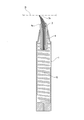
そして、このような構成からなる塗布具を使用する場合には、図4に示すように、毛先3の先端部3aを塗布媒体21(たとえば筆記具の場合は紙等)に向けて接触させ、塗布液を塗布媒体21に塗布する。この場合において、塗布液貯留部2に貯留されている塗布液10は、塗布液誘導部材4と接触しており、その塗布液誘導部材4が毛先3に接触しているので、塗布液は、塗布液誘導部材4から毛先3に誘導されて毛先3から塗布媒体21に塗布されることとなる。
この点をより詳細に説明すると、塗布液誘導部材4が多孔質材料である焼結樹脂で構成されており、また、塗布液誘導部材4の挿入孔13が、先端側の開口部13aから後端側の開口部13bに至って貫通して形成されているため、塗布液誘導部材4の後端部4bが塗布液貯留部2内の塗布液と接触している状態において、塗布液は塗布液誘導部材4に好適に吸収され、前記塗布液誘導部材4の後端部4b側から、該塗布液誘導部材4の先端部4a側に向かって、塗布液誘導部材4を構成する焼結樹脂の気孔中を移動することになる。
このように塗布液が塗布液誘導部材4を構成する焼結樹脂の気孔中を移動することにより、塗布液は、毛細管現象によって、塗布液誘導部材4の後端部4b側から先端部4a側に向かって誘導されることになる。
さらに、塗布液誘導部材4の挿入孔13の内周面が先端側に向かって幅狭なテーパ状に形成されているとともに、毛先を構成する繊維がテーパ状に形成されて、塗布液誘導部材4と毛先3とが密着した状態となっているため、塗布液誘導部材4によって誘導された塗布液は、その塗布液誘導部材4から毛先3の外周面側に好適に誘導されることとなり、誘導された塗布液は、塗布液誘導部材4側から毛先3側に確実に供給されることとなり、塗布媒体に良好な状態で塗布されることとなる。
このように、本実施形態では、塗布液誘導部材4を焼結樹脂で構成するとともに、塗布液誘導部材4の挿入孔13の内周面を後端側の開口部13bから先端側の開口部13aに向かって幅狭なテーパ状に形成し、毛先を構成するテーパ状に形成された繊維と密着しうる状態としたため、毛先3の周辺部側に位置する塗布液誘導部材4から、塗布液を毛先3に好適に供給することができることとなる。
尚、本実施形態においては、毛先3の後端部3bが、上記のように、塗布液誘導部材4の後端側の開口部13bよりわずかに突出するように、毛先3が挿入孔13に挿入されているので、その毛先3の後端部3bも塗布液貯留部2内の塗布液と接触した状態となっており、従って毛先3の後端部3b側から先端部3a側に向かっても、塗布液が誘導されることとなり、塗布液がより確実に毛先3に含浸することとなる。
また、上記図4のように、塗布媒体21に毛先3の先端部3aを接触させる際、その毛先3の先端部3aを塗布媒体21に押し付けることによって、同図のように毛先3の先端部3aが撓むことになる。
この場合において、上述のように、塗布液誘導部材4の挿入孔13の内周面が先端側に向かって幅狭なテーパ状に形成されているとともに、毛先を構成する繊維がテーパ状に形成されて、塗布液誘導部材4と毛先3とが密着した状態となっているため、塗布液誘導部材4と毛先3とは一体化した状態となり、しかも塗布液誘導部材4は、可撓性を有する焼結樹脂で構成されているので、上記図4のように毛先3の先端部3aが撓むことに伴って、塗布液誘導部材4も好適に撓むこととなる。
従って、先端側において、毛先3と塗布液誘導部材4とが一体となって塗布具を提供することができるのである。
(実施形態3)
本実施形態は、毛先3を塗布液誘導部材4に固定する手段の1つの実施形態である。本実施形態においては、図5に示すように、毛先3の後端部3b側に、ストッパー16が形成されている。本実施形態のストッパー16は、同図のように、鍔状に形成されたものである。
本実施形態は、毛先3を塗布液誘導部材4に固定する手段の1つの実施形態である。本実施形態においては、図5に示すように、毛先3の後端部3b側に、ストッパー16が形成されている。本実施形態のストッパー16は、同図のように、鍔状に形成されたものである。
このような鍔状のストッパー16が、毛先3の後端部3b側に形成されていることによって、そのストッパー16の部分が塗布液誘導部材4の後端部4bに係止されることとなり、それによって、毛先3が塗布液誘導部材4から抜け出るのを好適に防止することができる。
(実施形態4)
本実施形態は、毛先3を塗布液誘導部材4に固定する手段の他の実施形態である。本実施形態においては、ストッパー16は、たとえば毛先3の後端部3b側を熱融解することによって、或いは毛先3の後端部3b側に接着剤を含浸させることによって形成されている。ストッパー16の形状は、上記実施形態3のような鍔状ではなく、図6のように略球状に形成されているが、その形状は問うものではない。
本実施形態は、毛先3を塗布液誘導部材4に固定する手段の他の実施形態である。本実施形態においては、ストッパー16は、たとえば毛先3の後端部3b側を熱融解することによって、或いは毛先3の後端部3b側に接着剤を含浸させることによって形成されている。ストッパー16の形状は、上記実施形態3のような鍔状ではなく、図6のように略球状に形成されているが、その形状は問うものではない。
本実施形態においても、毛先3の後端部3b側のストッパー17によって、毛先3が塗布液誘導部材4から抜け出るのを好適に防止することができる。
(実施形態5)
本実施形態においては、図7に示すように、軸筒1の先端部1a側の外周面5が、緩やかなテーパ面状に形成されており、この点で軸筒1の先端部1a側の外周面5が真っ直ぐに形成されていた上記実施形態1と相違している。
本実施形態においては、図7に示すように、軸筒1の先端部1a側の外周面5が、緩やかなテーパ面状に形成されており、この点で軸筒1の先端部1a側の外周面5が真っ直ぐに形成されていた上記実施形態1と相違している。
本実施形態においても、上記実施形態1と同様に、軸筒1の先端部1a側の内周面6が塗布液誘導部材4の外周面と接触しうるように形成されているが、本実施形態においては、塗布液誘導部材4の後端部4bのみならず、塗布液誘導部材4の側面も塗布液に接触するように、塗布液誘導部材4が塗布液貯留部2内に臨出している。
また、本実施形態では、図7に示すように、挿入孔13が、先端部側にのみ開口部13aを有する凹状に形成されており、その点で挿入孔13が貫通して形成されていた実施形態1、2と相違している。そして、毛先3は、このような凹状の挿入孔13内に嵌合されている。
本実施形態においては、塗布液貯留部2に貯留されている塗布液10が、塗布液誘導部材4の後端部4bのみならず、塗布液誘導部材4の側面にも接触している。塗布液誘導部材4が焼結樹脂で構成されている点、その他の構成は、上記実施形態2と共通するため、その詳細な説明は省略する。
本実施形態では、凹状の挿入孔13に毛先3が嵌入されているので、毛先3が直接塗布液に接触しているわけではないが、毛先3を挿入孔13に嵌入させている塗布液誘導部材4が焼結樹脂で構成され、且つ塗布液貯留部2に貯留されている塗布液10が、塗布液誘導部材4の後端部4bのみならず、塗布液誘導部材4の側面にも接触しているので、塗布液は塗布液誘導部材4に好適に含浸されることとなる。そして、塗布液誘導部材4の挿入孔13に毛先3が嵌入されて、その塗布液誘導部材4が毛先3に接触しているので、塗布液は、塗布液誘導部材4から毛先3に誘導されることとなる。
この場合において、塗布液誘導部材4の挿入孔13の内周面が先端側に向かって幅狭なテーパ状に形成されているとともに、毛先を構成する繊維がテーパ状に形成されて、塗布液誘導部材4と毛先3とが密着した状態となっているため、塗布液誘導部材4によって誘導された塗布液は、その塗布液誘導部材4から毛先3の外周面側に好適に誘導されることとなり、誘導された塗布液は、塗布液誘導部材4側から毛先3側に確実に供給されることとなり、塗布媒体に良好な状態で塗布されることとなる。
このように、本実施形態においても、塗布液誘導部材4を焼結樹脂で構成するとともに、塗布液誘導部材4の挿入孔13の内周面を先端側に向かって幅狭なテーパ状に形成し、毛先を構成するテーパ状に形成された繊維と密着しうる状態としたため、毛先3の周辺部側に位置する塗布液誘導部材4から、塗布液を毛先3に好適に供給することができることとなる。
尚、本実施形態では、塗布液誘導部材4を焼結樹脂で構成する場合について説明したが、これに限らず、たとえば合成繊維をバインダーで結合することによって得られた素材で塗布液誘導部材4を構成することも可能である。
(実施形態6)
本実施形態においては、図8に示すように、塗布液貯留部2内に中綿9が装填されており、この点で塗布液が直接塗布液貯留部2内に貯留されていた上記実施形態1、2、5と相違している。
本実施形態においては、図8に示すように、塗布液貯留部2内に中綿9が装填されており、この点で塗布液が直接塗布液貯留部2内に貯留されていた上記実施形態1、2、5と相違している。
すなわち、本実施形態では、繊維の集合体で構成した中綿9に塗布液を含浸させており、その中綿9に、塗布液誘導部材4の後端部4bを差し込むことによって、塗布液誘導部材4を塗布液の接触させている。塗布液誘導部材4の後端部4bは、中綿9に差し込み易いように、胴体部分よりも細く形成されている。
尚、中綿9の素材としては、たとえば天然繊維、ポリアセタール系樹脂、アクリル系樹脂、ポリエステル系樹脂、ポリアミド系樹脂、ポリウレタン系樹脂、ポリオレフィン系樹脂、ポリビニル系樹脂、ポリエーテル系樹脂、ポリフェニレン系樹脂等からなる繊維を使用して束ねたもの、或いはスポンジ等が用いられる。
塗布具が、塗布液貯留部2を備えた軸筒1、毛先3、塗布液誘導部材4を具備して構成されている点、軸筒1の先端部1a側の外周面5が緩やかなテーパ面状に形成されている点、軸筒1の先端部1a側の内周面6が塗布液誘導部材4の外周面と接触しうるように形成されている点、塗布液誘導部材4が焼結樹脂で構成されている点、塗布液誘導部材4に凹状の挿入孔13が形成され、その挿入孔13内に毛先3が嵌合されている点、塗布液誘導部材4の全体が略円柱状に形成されている点、軸筒1の後端部1b側に小孔8が穿設されている点等は実施形態5と同じである。
本実施形態では、上記実施形態1、2、5のように、塗布液誘導部材4が塗布液に直接接触しているのではないが、塗布液を含浸させた中綿9に塗布液誘導部材4の後端部4bを差し込むことによって、塗布液誘導部材4を中綿9に接触させているので、中綿9に含浸された塗布液が塗布液誘導部材4に誘導され、さらに塗布液誘導部材4から毛先3に誘導されることとなる。
この場合において、本実施形態においても、上記実施形態5と同様に、毛先3が塗布液誘導部材4の凹状の挿入孔13内に嵌合され、塗布液誘導部材4の挿入孔13の内周面が先端側に向かって幅狭なテーパ状に形成されているとともに、毛先を構成する繊維がテーパ状に形成されて、塗布液誘導部材4と毛先3とが密着した状態となっているため、塗布液誘導部材4に含浸、保持された塗布液は、毛先3の周辺部側から毛先3に供給されることとなり、塗布液誘導部材4側から毛先3側に確実に供給されることとなるのである。
尚、本実施形態では、塗布液誘導部材4を焼結樹脂で構成する場合について説明したが、これに限らず、たとえば合成繊維をバインダーで結合することによって得られた素材で塗布液誘導部材4を構成することも可能である。
(実施形態7)
本実施形態においては、図9に示すように、塗布液誘導部材4の外周面が、緩やかなテーパ面状に形成されており、この塗布液誘導部材4が軸筒1の先端部1a側の開口部11に装着されている。すなわち、本実施形態では、軸筒1の先端部1aが、上記実施形態1のように所定の厚さを有し、その内周面6に塗布液誘導部材4が挿入されて該軸筒1の先端部1aで塗布液誘導部材4を保持しているという状態ではなく、全体が同程度の薄い円筒状に形成された軸筒1の開口部11に塗布液誘導部材4が装着されて、塗布液誘導部材4自体が軸筒1の先端部を構成しているような形態とされている。
本実施形態においては、図9に示すように、塗布液誘導部材4の外周面が、緩やかなテーパ面状に形成されており、この塗布液誘導部材4が軸筒1の先端部1a側の開口部11に装着されている。すなわち、本実施形態では、軸筒1の先端部1aが、上記実施形態1のように所定の厚さを有し、その内周面6に塗布液誘導部材4が挿入されて該軸筒1の先端部1aで塗布液誘導部材4を保持しているという状態ではなく、全体が同程度の薄い円筒状に形成された軸筒1の開口部11に塗布液誘導部材4が装着されて、塗布液誘導部材4自体が軸筒1の先端部を構成しているような形態とされている。
さらに、本実施形態では、上記実施形態5、6のような凹状の挿入孔13ではなく、実施形態1、2と同様に貫通された挿入孔13が塗布液誘導部材4に形成されており、その挿入孔13に毛先3が挿入されている。このように毛先3が挿入孔13に挿入された状態において、毛先3の後端部3bは塗布液貯留部2内に臨出して塗布液10に接触した状態となっている。また、塗布液誘導部材4の後端部側も塗布液10に接触している。
さらに、本実施形態では、合成樹脂製フィルムからなる被膜12が、塗布液誘導部材4及び軸筒1の外周面に被着されている。これは、本実施形態では、緩やかなテーパ面状に形成された塗布液誘導部材4の先端部側が把持される可能性があり、その塗布液誘導部材4に塗布液が含浸されて手に付着するおそれがあるので、これを防止するためである。この被膜12は、本実施形態では塗布液誘導部材4から軸筒1に跨がって被着されているが、塗布液誘導部材4のみに被着することも可能であり、塗布液誘導部材4に被着されていれば、塗布液が手に付着するのを防止するという目的は一応達成される。
塗布具が、塗布液貯留部2を備えた軸筒1、毛先3、塗布液誘導部材4を具備して構成されている点、塗布液誘導部材4が焼結樹脂で構成されている点、軸筒1の後端部1b側に小孔8が穿設されている点等は実施形態1、5、6等と同じである。
本実施形態では、塗布液誘導部材4が塗布液に接触しているだけでなく、毛先3自体も塗布液に接触した状態とされている。従って、本実施形態では、塗布液誘導部材4側から塗布液が毛先3に誘導されるだけでなく、塗布液が直接毛先3に誘導されることにもなる。
本実施形態においては、塗布液誘導部材4に挿入孔13が形成され、その挿入孔13に毛先3が挿入されているので、毛先の外周面は塗布液誘導部材4の挿入孔13の内周面と面接触状態となり、従って本実施形態においても、塗布液は毛先3の外周面側から毛先3に供給されることとなり、塗布液誘導部材4側から毛先3側に確実に供給されることとなる。
(実施形態8)
本実施形態においては、軸筒1に塗布液貯留部2が設けられておらず、別途準備された塗布液に毛先3が直接浸漬され、そのようにして毛先3に含浸された塗布液が塗布媒体に塗布されることとなる。また、上記各実施形態と同様に、塗布液誘導部材4には挿入孔13が形成され、該挿入孔13の内周面が先端側に向かって幅狭なテーパ状に形成されている。そして、その挿入孔13に、繊維がテーパ状に形成された毛先3が挿入されており、毛先3が塗布液誘導部材4の挿入孔13の内周面に密着する状態で挿入され、毛先3に含浸された塗布液が塗布液誘導部材4にも含浸される構造とされている。
本実施形態においては、軸筒1に塗布液貯留部2が設けられておらず、別途準備された塗布液に毛先3が直接浸漬され、そのようにして毛先3に含浸された塗布液が塗布媒体に塗布されることとなる。また、上記各実施形態と同様に、塗布液誘導部材4には挿入孔13が形成され、該挿入孔13の内周面が先端側に向かって幅狭なテーパ状に形成されている。そして、その挿入孔13に、繊維がテーパ状に形成された毛先3が挿入されており、毛先3が塗布液誘導部材4の挿入孔13の内周面に密着する状態で挿入され、毛先3に含浸された塗布液が塗布液誘導部材4にも含浸される構造とされている。
このような構成からなる点で、塗布液貯留部2内の塗布液10又は中綿9に塗布液誘導部材4が接触して、塗布液が自給式となるように構成されていた上記各実施形態塗布具と相違している。また塗布液貯留部2が存在しないので、本実施形態では軸筒1が中実状とされ、この点で軸筒1が中空状に形成されていた上記各実施形態と相違する。
本実施形態では、図10に示すように、中実状の軸筒1の先端部1aに凹部14が形成され、その凹部14内に塗布液誘導部材4が嵌合されて取り付けられている。また、この凹部14に連通して該凹部14よりも小径の凹部15が形成されている。そして、この小径の凹部15内に毛先3が嵌合されて取り付けられている。
塗布液誘導部材4としては、焼結樹脂で構成したものや、合成繊維をバインダーで結合させて構成したものを用いることができる。
本実施形態の塗布具は、上述のように塗布液自給式の塗布具ではないので、毛先3を、別途準備された塗布液に直接浸漬し、塗布媒体に塗布することによって使用される。この場合において、塗布液誘導部材4には上記のように挿入孔13が形成され、その挿入孔13に毛先3が挿入されて、毛先3の塗布液誘導部材4の挿入孔13の内周面と密着状態とされているため、毛先3に含浸された塗布液は塗布液誘導部材4にも含浸されることとなり、一定時間保持されることとなる。
従って、塗布液誘導部材4に保持された塗布液は、逆に塗布液誘導部材4側から毛先3側へ誘導されることとなり、そのように誘導された塗布液も、毛先3により塗布媒体に塗布されることとなる。
本実施形態では、上記各実施形態と同様に、塗布液誘導部材4に挿入孔13が形成され、その挿入孔13の内周面が先端側に向かって幅狭なテーパ状に形成されている。そして、その挿入孔13に、繊維がテーパ状に形成された毛先3が挿入されており、毛先3が塗布液誘導部材4の挿入孔13の内周面に密着する状態で挿入されている。
このように、本実施形態では、毛先3に直接塗布液が接触して含浸される他、その毛先3側から塗布液誘導部材4側へ誘導された塗布液が、塗布液誘導部材4で一定時間保持され、逆に塗布液誘導部材4側から毛先3側へ誘導されることになるので、一般の直液式の塗布等に比べると、塗布媒体に良好な状態で塗布することができる。
(実施形態9)
本実施形態では、図11に示すように、先軸と称されるアダプター18が、軸筒1の先端側に圧入されて取り付けられている。アダプター18の先端側はテーパ状に形成され、また塗布液誘導部材4の先端側もテーパ状に形成されている。このように形成されることによって、アダプター18が、軸筒1の先端側に圧入される際に、塗布液誘導部材4が収縮し、それによって毛先3が固定されることになる。
本実施形態では、図11に示すように、先軸と称されるアダプター18が、軸筒1の先端側に圧入されて取り付けられている。アダプター18の先端側はテーパ状に形成され、また塗布液誘導部材4の先端側もテーパ状に形成されている。このように形成されることによって、アダプター18が、軸筒1の先端側に圧入される際に、塗布液誘導部材4が収縮し、それによって毛先3が固定されることになる。
また本実施形態においても、上記実施形態8と同様に、塗布液誘導部材4に形成された挿入孔13に毛先3が挿入されているが、本実施形態では塗布液誘導部材4の下部に合成樹脂製の支持体19が取り付けられ、その支持体19の先端側に形成された凹部20内に毛先3の後端部3bが取り付けられている。
従って、本実施形態では、毛先3は塗布液10に直接接触してはおらず、実施形態1等と同様に、塗布液誘導部材4のみが塗布液10と接触しているので、塗布液誘導部材4に含浸、保持された塗布液が、毛先3の外周面側から毛先3に供給されることとなるのである。
(その他の実施形態)
尚、塗布液誘導部材4の形状、構造、及び塗布液誘導部材4への毛先3の取付手段は上記実施形態に限定されるものではなく、要は、毛先3の周辺部側から毛先3へ塗布液が誘導されるように構成されていればよい。
尚、塗布液誘導部材4の形状、構造、及び塗布液誘導部材4への毛先3の取付手段は上記実施形態に限定されるものではなく、要は、毛先3の周辺部側から毛先3へ塗布液が誘導されるように構成されていればよい。
また、塗布液誘導部材4の材質も、上記実施形態の、合成樹脂の成形体、焼結ポリエチレンのような焼結樹脂、合成繊維をバインダーで結合させて構成したものに限らず、たとえば発泡性合成樹脂で構成することも可能であり、さらにはこれ以外の素材、たとえばセラミックの発泡体、発泡金属、焼結金属多孔質体等で構成することも可能である。要は、塗布液を含浸することができ、毛先3側へ塗布液を誘導しうるような素材で構成されていればよいのである。
さらに毛先3の材質も、上記実施形態のポリエチレンテレフタレートやポリブチレンテレフタレート等のポリエステル繊維、ポリアミド繊維等に限定されるものではなく、これ以外の合成繊維で構成することも可能であり、さらには、天然繊維で構成することも可能であり、毛先3の材質は問うものではない。
さらに、中綿9の材質も、上記実施形態の天然繊維、ポリアセタール系樹脂、アクリル系樹脂、ポリエステル系樹脂、ポリアミド系樹脂、ポリウレタン系樹脂、ポリオレフィン系樹脂、ポリビニル系樹脂、PP系樹脂、ポリエーテル系樹脂、ポリフェニレン系樹脂等からなる繊維を使用して束ねたもの、或いはスポンジ等に限定されるものではなく、これ以外のものを使用することも可能である。
さらに、塗布具の用途も、筆記具に限らず、化粧用具に使用することも可能である。
3 毛先
4 塗布液誘導部材
13 挿入孔
16 ストッパー
17 塗布液誘導用孔
4 塗布液誘導部材
13 挿入孔
16 ストッパー
17 塗布液誘導用孔
Claims (16)
- 塗布液を含浸可能で、該塗布液を塗布媒体に塗布可能な毛先(3)を有する塗布具において、前記毛先(3)側へ塗布液を誘導することができる塗布液誘導部材(4)が具備されていることを特徴とする塗布具。
- 塗布液誘導部材(4)に、毛先(3)を挿入するための挿入孔(13)が形成されている請求項1記載の塗布具。
- 挿入孔(13)側へ毛細管現象によって塗布液を誘導しうるような塗布液誘導用孔(17)が、前記挿入孔(13)に連通して塗布液誘導部材(4)に形成されている請求項2記載の塗布具。
- 塗布液誘導用孔(17)が、挿入孔(13)を中心として該挿入孔(13)から外側に向かって放射状に形成された複数の細孔によって構成されている請求項3記載の塗布具。
- 塗布液誘導部材(4)の挿入孔(13)が、毛先(3)の先端部(3a)を突出させる先端側の開口部(13a)と、該毛先(3)の後端部(3b)が塗布液と接触しうるように開口して形成された後端側の開口部(13b)とに貫通して形成されている請求項2記載の塗布具。
- 挿入孔(13)の後端側の開口部(13b)より幅広に形成されて、塗布液誘導部材(4)の後端部(4b)側に係止可能となるように、毛先(3)の後端部(3b)側にストッパー(16)が形成されている請求項5記載の塗布具。
- テーパ状繊維が多数本束ねられて毛先(3)が構成されている請求項1記載の塗布具。
- 塗布液誘導部材(4)の挿入孔(13)の内周面が、先端側に向かって幅狭なテーパ状に形成されている請求項2記載の塗布具。
- 塗布液誘導部材(4)が、多孔質材料で構成されている請求項1記載の塗布具。
- 塗布液誘導部材(4)を構成する多孔質材料の孔径が20~80μmである請求項9記載の塗布具。
- 塗布液誘導部材(4)が、合成樹脂製成形体で構成されている請求項1記載の塗布具。
- 塗布液誘導部材(4)が、焼結樹脂で構成されている請求項1記載の塗布具。
- 塗布液誘導部材(4)が、発泡性合成樹脂、セラミックの発泡体、発泡金属、焼結金属多孔質体、又は合成繊維をバインダーで結合させた素材で構成されている請求項1記載の塗布具。
- 塗布液誘導部材(4)が可撓性を有して構成されている請求項1記載の塗布具。
- 挿入孔(13)が、後端側の開口部を有しない凹状のものである請求項2記載の塗布具。
- 毛先(3)が、塗布液誘導部材(4)の挿入孔(13)の内周面に面接触状態となるように挿入されている請求項2記載の塗布具。
Applications Claiming Priority (2)
| Application Number | Priority Date | Filing Date | Title |
|---|---|---|---|
| JP2009-141519 | 2009-06-12 | ||
| JP2009141519A JP2010284927A (ja) | 2009-06-12 | 2009-06-12 | 塗布具 |
Publications (1)
| Publication Number | Publication Date |
|---|---|
| WO2010143325A1 true WO2010143325A1 (ja) | 2010-12-16 |
Family
ID=43308589
Family Applications (1)
| Application Number | Title | Priority Date | Filing Date |
|---|---|---|---|
| PCT/JP2009/071281 Ceased WO2010143325A1 (ja) | 2009-06-12 | 2009-12-22 | 塗布具 |
Country Status (2)
| Country | Link |
|---|---|
| JP (1) | JP2010284927A (ja) |
| WO (1) | WO2010143325A1 (ja) |
Cited By (7)
| Publication number | Priority date | Publication date | Assignee | Title |
|---|---|---|---|---|
| JP2015002984A (ja) * | 2013-05-21 | 2015-01-08 | 三菱鉛筆株式会社 | コレクター式塗布具 |
| CN108340703A (zh) * | 2018-03-09 | 2018-07-31 | 绩溪县上庄老胡开文墨厂 | 一种注墨毛笔 |
| CN108407491A (zh) * | 2018-03-09 | 2018-08-17 | 绩溪县上庄老胡开文墨厂 | 一种注墨毛笔 |
| CN108407494A (zh) * | 2018-03-09 | 2018-08-17 | 绩溪县上庄老胡开文墨厂 | 一种注墨毛笔 |
| CN108407495A (zh) * | 2018-03-09 | 2018-08-17 | 绩溪县上庄老胡开文墨厂 | 一种注墨毛笔 |
| CN108407493A (zh) * | 2018-03-09 | 2018-08-17 | 绩溪县上庄老胡开文墨厂 | 一种注墨毛笔 |
| CN109937068A (zh) * | 2016-10-28 | 2019-06-25 | 尼普洛株式会社 | 涂敷器以及药液涂敷器 |
Families Citing this family (2)
| Publication number | Priority date | Publication date | Assignee | Title |
|---|---|---|---|---|
| JP6286831B2 (ja) * | 2013-01-31 | 2018-03-07 | ぺんてる株式会社 | 塗布具 |
| JP6745387B2 (ja) * | 2019-06-27 | 2020-08-26 | 三菱鉛筆株式会社 | 塗布具 |
Citations (5)
| Publication number | Priority date | Publication date | Assignee | Title |
|---|---|---|---|---|
| JPS5542504U (ja) * | 1978-08-31 | 1980-03-19 | ||
| JPS5734488U (ja) * | 1980-08-06 | 1982-02-23 | ||
| JPS59126686U (ja) * | 1983-02-15 | 1984-08-25 | ぺんてる株式会社 | 毛筆状筆記具 |
| JPH0789288A (ja) * | 1992-01-28 | 1995-04-04 | Coronet Werke Gmbh | 液体を付与する装置 |
| JP4395189B1 (ja) * | 2008-08-29 | 2010-01-06 | 株式会社ソリトン | 塗布具 |
-
2009
- 2009-06-12 JP JP2009141519A patent/JP2010284927A/ja not_active Withdrawn
- 2009-12-22 WO PCT/JP2009/071281 patent/WO2010143325A1/ja not_active Ceased
Patent Citations (5)
| Publication number | Priority date | Publication date | Assignee | Title |
|---|---|---|---|---|
| JPS5542504U (ja) * | 1978-08-31 | 1980-03-19 | ||
| JPS5734488U (ja) * | 1980-08-06 | 1982-02-23 | ||
| JPS59126686U (ja) * | 1983-02-15 | 1984-08-25 | ぺんてる株式会社 | 毛筆状筆記具 |
| JPH0789288A (ja) * | 1992-01-28 | 1995-04-04 | Coronet Werke Gmbh | 液体を付与する装置 |
| JP4395189B1 (ja) * | 2008-08-29 | 2010-01-06 | 株式会社ソリトン | 塗布具 |
Cited By (7)
| Publication number | Priority date | Publication date | Assignee | Title |
|---|---|---|---|---|
| JP2015002984A (ja) * | 2013-05-21 | 2015-01-08 | 三菱鉛筆株式会社 | コレクター式塗布具 |
| CN109937068A (zh) * | 2016-10-28 | 2019-06-25 | 尼普洛株式会社 | 涂敷器以及药液涂敷器 |
| CN108340703A (zh) * | 2018-03-09 | 2018-07-31 | 绩溪县上庄老胡开文墨厂 | 一种注墨毛笔 |
| CN108407491A (zh) * | 2018-03-09 | 2018-08-17 | 绩溪县上庄老胡开文墨厂 | 一种注墨毛笔 |
| CN108407494A (zh) * | 2018-03-09 | 2018-08-17 | 绩溪县上庄老胡开文墨厂 | 一种注墨毛笔 |
| CN108407495A (zh) * | 2018-03-09 | 2018-08-17 | 绩溪县上庄老胡开文墨厂 | 一种注墨毛笔 |
| CN108407493A (zh) * | 2018-03-09 | 2018-08-17 | 绩溪县上庄老胡开文墨厂 | 一种注墨毛笔 |
Also Published As
| Publication number | Publication date |
|---|---|
| JP2010284927A (ja) | 2010-12-24 |
Similar Documents
| Publication | Publication Date | Title |
|---|---|---|
| WO2010143325A1 (ja) | 塗布具 | |
| CN107074002A (zh) | 笔及笔用笔芯 | |
| JP6804267B2 (ja) | 筆先ユニット及び筆先ユニットを用いた液体塗布具 | |
| JP2018122566A (ja) | 筆記具 | |
| JP2026040790A (ja) | 筆記具 | |
| JP4395189B1 (ja) | 塗布具 | |
| JP2021115761A (ja) | ペン先、中継芯、及び、該ペン先又は中継芯を備える液体塗布具 | |
| JP7638630B2 (ja) | 筆記具 | |
| JP2012101395A (ja) | 塗布具 | |
| US11427027B2 (en) | Writing implement | |
| JP7258954B2 (ja) | 筆記具 | |
| JP7158203B2 (ja) | 塗布具 | |
| JP5795042B2 (ja) | 圧力変動緩衝機構及び塗布具 | |
| CN114762553A (zh) | 液体化妆品材料容器 | |
| CN116348309A (zh) | 书写工具用纤维束体、使用其的笔尖、书写工具 | |
| JP2023083886A (ja) | 筆先ユニット、筆先ユニットの製造方法、及び、筆先ユニットを用いた液体塗布具 | |
| JP2010149441A (ja) | 液体塗布具 | |
| JP2010269133A (ja) | 液体供給体及び該液体供給体を用いた筆先構造 | |
| JP5457695B2 (ja) | 化粧料の塗布具 | |
| JP6262463B2 (ja) | 液体塗布具 | |
| JP2005313404A (ja) | 筆記具 | |
| JP2014037074A (ja) | 液体塗布具 | |
| JP2018126210A (ja) | 液体塗布容器 | |
| JP7042556B2 (ja) | 筆記具 | |
| JP2021030463A (ja) | 筆記具 |
Legal Events
| Date | Code | Title | Description |
|---|---|---|---|
| 121 | Ep: the epo has been informed by wipo that ep was designated in this application |
Ref document number: 09845847 Country of ref document: EP Kind code of ref document: A1 |
|
| NENP | Non-entry into the national phase |
Ref country code: DE |
|
| 122 | Ep: pct application non-entry in european phase |
Ref document number: 09845847 Country of ref document: EP Kind code of ref document: A1 |