WO2010143333A1 - Dispositif d'affichage, dispositif d'affichage à cristaux liquides, procédé de pilotage de dispositif d'affichage et récepteur de télévision - Google Patents
Dispositif d'affichage, dispositif d'affichage à cristaux liquides, procédé de pilotage de dispositif d'affichage et récepteur de télévision Download PDFInfo
- Publication number
- WO2010143333A1 WO2010143333A1 PCT/JP2010/000946 JP2010000946W WO2010143333A1 WO 2010143333 A1 WO2010143333 A1 WO 2010143333A1 JP 2010000946 W JP2010000946 W JP 2010000946W WO 2010143333 A1 WO2010143333 A1 WO 2010143333A1
- Authority
- WO
- WIPO (PCT)
- Prior art keywords
- display
- frame
- subframe
- data
- light
- Prior art date
- Legal status (The legal status is an assumption and is not a legal conclusion. Google has not performed a legal analysis and makes no representation as to the accuracy of the status listed.)
- Ceased
Links
Images


Classifications
-
- G—PHYSICS
- G09—EDUCATION; CRYPTOGRAPHY; DISPLAY; ADVERTISING; SEALS
- G09G—ARRANGEMENTS OR CIRCUITS FOR CONTROL OF INDICATING DEVICES USING STATIC MEANS TO PRESENT VARIABLE INFORMATION
- G09G3/00—Control arrangements or circuits, of interest only in connection with visual indicators other than cathode-ray tubes
- G09G3/20—Control arrangements or circuits, of interest only in connection with visual indicators other than cathode-ray tubes for presentation of an assembly of a number of characters, e.g. a page, by composing the assembly by combination of individual elements arranged in a matrix no fixed position being assigned to or needed to be assigned to the individual characters or partial characters
- G09G3/34—Control arrangements or circuits, of interest only in connection with visual indicators other than cathode-ray tubes for presentation of an assembly of a number of characters, e.g. a page, by composing the assembly by combination of individual elements arranged in a matrix no fixed position being assigned to or needed to be assigned to the individual characters or partial characters by control of light from an independent source
- G09G3/36—Control arrangements or circuits, of interest only in connection with visual indicators other than cathode-ray tubes for presentation of an assembly of a number of characters, e.g. a page, by composing the assembly by combination of individual elements arranged in a matrix no fixed position being assigned to or needed to be assigned to the individual characters or partial characters by control of light from an independent source using liquid crystals
- G09G3/3611—Control of matrices with row and column drivers
-
- G—PHYSICS
- G09—EDUCATION; CRYPTOGRAPHY; DISPLAY; ADVERTISING; SEALS
- G09G—ARRANGEMENTS OR CIRCUITS FOR CONTROL OF INDICATING DEVICES USING STATIC MEANS TO PRESENT VARIABLE INFORMATION
- G09G3/00—Control arrangements or circuits, of interest only in connection with visual indicators other than cathode-ray tubes
- G09G3/20—Control arrangements or circuits, of interest only in connection with visual indicators other than cathode-ray tubes for presentation of an assembly of a number of characters, e.g. a page, by composing the assembly by combination of individual elements arranged in a matrix no fixed position being assigned to or needed to be assigned to the individual characters or partial characters
- G09G3/2007—Display of intermediate tones
- G09G3/2018—Display of intermediate tones by time modulation using two or more time intervals
- G09G3/2022—Display of intermediate tones by time modulation using two or more time intervals using sub-frames
- G09G3/2025—Display of intermediate tones by time modulation using two or more time intervals using sub-frames the sub-frames having all the same time duration
-
- G—PHYSICS
- G09—EDUCATION; CRYPTOGRAPHY; DISPLAY; ADVERTISING; SEALS
- G09G—ARRANGEMENTS OR CIRCUITS FOR CONTROL OF INDICATING DEVICES USING STATIC MEANS TO PRESENT VARIABLE INFORMATION
- G09G3/00—Control arrangements or circuits, of interest only in connection with visual indicators other than cathode-ray tubes
- G09G3/20—Control arrangements or circuits, of interest only in connection with visual indicators other than cathode-ray tubes for presentation of an assembly of a number of characters, e.g. a page, by composing the assembly by combination of individual elements arranged in a matrix no fixed position being assigned to or needed to be assigned to the individual characters or partial characters
- G09G3/2007—Display of intermediate tones
- G09G3/2077—Display of intermediate tones by a combination of two or more gradation control methods
- G09G3/2081—Display of intermediate tones by a combination of two or more gradation control methods with combination of amplitude modulation and time modulation
-
- G—PHYSICS
- G09—EDUCATION; CRYPTOGRAPHY; DISPLAY; ADVERTISING; SEALS
- G09G—ARRANGEMENTS OR CIRCUITS FOR CONTROL OF INDICATING DEVICES USING STATIC MEANS TO PRESENT VARIABLE INFORMATION
- G09G2320/00—Control of display operating conditions
- G09G2320/02—Improving the quality of display appearance
- G09G2320/0247—Flicker reduction other than flicker reduction circuits used for single beam cathode-ray tubes
-
- G—PHYSICS
- G09—EDUCATION; CRYPTOGRAPHY; DISPLAY; ADVERTISING; SEALS
- G09G—ARRANGEMENTS OR CIRCUITS FOR CONTROL OF INDICATING DEVICES USING STATIC MEANS TO PRESENT VARIABLE INFORMATION
- G09G2320/00—Control of display operating conditions
- G09G2320/02—Improving the quality of display appearance
- G09G2320/0261—Improving the quality of display appearance in the context of movement of objects on the screen or movement of the observer relative to the screen
-
- G—PHYSICS
- G09—EDUCATION; CRYPTOGRAPHY; DISPLAY; ADVERTISING; SEALS
- G09G—ARRANGEMENTS OR CIRCUITS FOR CONTROL OF INDICATING DEVICES USING STATIC MEANS TO PRESENT VARIABLE INFORMATION
- G09G2320/00—Control of display operating conditions
- G09G2320/02—Improving the quality of display appearance
- G09G2320/0271—Adjustment of the gradation levels within the range of the gradation scale, e.g. by redistribution or clipping
- G09G2320/0276—Adjustment of the gradation levels within the range of the gradation scale, e.g. by redistribution or clipping for the purpose of adaptation to the characteristics of a display device, i.e. gamma correction
-
- G—PHYSICS
- G09—EDUCATION; CRYPTOGRAPHY; DISPLAY; ADVERTISING; SEALS
- G09G—ARRANGEMENTS OR CIRCUITS FOR CONTROL OF INDICATING DEVICES USING STATIC MEANS TO PRESENT VARIABLE INFORMATION
- G09G2330/00—Aspects of power supply; Aspects of display protection and defect management
- G09G2330/02—Details of power systems and of start or stop of display operation
- G09G2330/021—Power management, e.g. power saving
Definitions
- the present invention relates to a display device (for example, a liquid crystal display device) capable of performing frame display by the sum of display of a plurality of subframes.
- a display device for example, a liquid crystal display device
- the luminance is different between when the liquid crystal panel is viewed from an oblique direction and when viewed from the front direction.
- the difference between the luminance that should be displayed (scheduled luminance) and the luminance that is actually displayed (actual luminance) is the minimum luminance (minimum gradation) or the maximum. While it is 0 in the case of luminance (maximum gradation), it is maximum in intermediate luminance (halftone).
- Such a phenomenon is generally referred to as “brightness floating (white floating)”.
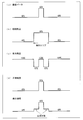
- FIG. 20A shows the display luminance of the input image data
- FIG. 20B shows the amount of light per frame of the illumination area
- FIG. 20C shows the light transmittance of the liquid crystal assumed in the display area.
- D shows the luminance when the liquid crystal panel is viewed from the front direction and the luminance when the liquid crystal panel is viewed from the oblique direction.
- Patent Document 1 and Patent Document 2 disclose techniques for suppressing such brightness floating (white floating).
- the liquid crystal display device of Patent Document 1 has a configuration in which one frame is divided into a plurality of subframes (for example, a first subframe and a second subframe), and input data is displayed by a sum of display of each subframe.
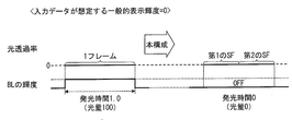
- a display method of this liquid crystal display device is shown in FIGS. Note that the input data assumes a minimum display luminance of 0 to a maximum display luminance of 100.
- the backlight (BL) is lit in the same state for one frame period (light quantity is 100 in one frame), and the first sub
- the light transmittance is set to 60% for the frame, and the light transmittance is set to 100% for the second subframe.
- the backlight is turned on in the same state during one frame period (the amount of light is 100 in one frame), and the first subframe. Is set to 20%, and the second subframe is set to 100%.
- the backlight is turned on in the same state during one frame period (the amount of light is 100 in one frame), and the first subframe. Is set to 0 percent light transmittance, and the second subframe is set to 20 percent light transmittance.
- the luminance shift in the intermediate luminance (halftone) is reduced, so that the luminance floating can be suppressed.
- any sub-frame (the first sub-frame in the above example) is a dark sub-frame for most input data
- the backlight state is one frame. Since it is constant during the period, this dark subframe is floated due to light leakage or the like, and there is a problem that the effect of subframe display is reduced. Furthermore, since the backlight state is constant regardless of the dark subframe and the bright subframe, there is a problem that wasteful power is consumed.
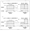
- FIG. 23 is a block diagram showing a schematic configuration of the liquid crystal display device of Patent Document 3.
- the liquid crystal display device 110 has a configuration in which a plurality of illumination areas are provided and the amount of light in each illumination area is individually adjusted, and the light transmittance of each subframe is set based on the amount of light.
- a specific example will be described.
- the backlight control unit obtains the display brightness of the frame data DF.
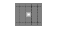
- the display area HAR0 see FIG. 2 of the liquid crystal panel
- the backlight control unit sets the amount of light per frame of the illumination area LAR0 (see FIG. 3) of the area active backlight corresponding to the display area HAR0 to 80. decide. That is, the backlight control unit sets the light emission time of the illumination area LAR0 to be 0.8 frames, makes the light emission state in the 0.2 frame period from the start of the frame, and sets the light emission state in the remaining 0.8 frame period. .
- first subframe data DSF1 indicating 100% light transmittance and second subframe data DSF2 indicating 100% light transmittance are generated.
- the display brightness is 0 even if the light transmittance on the display area HAR0 side is set to 100%.
- the display luminance is 100 if the light transmittance on the display area HAR0 side is 100%. If this is schematically shown, the configuration of FIG. 24A is obtained, and it can be seen that sub-frame display can be performed while suppressing the amount of light in the illumination area LAR0.
- first subframe data DSF1 indicating 33% light transmittance and second subframe data DSF2 indicating 100% light transmittance are generated.
- the display brightness is 0 even if the light transmittance on the display area HAR0 side is set to 33%.
- the display luminance is 33 if the light transmittance on the display area HAR0 side is 33%, and the display luminance if the light transmittance is 100%. Is also 100. If this is represented schematically, it becomes the structure of FIG.24 (b), and it turns out that a sub-frame display can be performed, suppressing the light quantity of illumination area LAR0.
- the display quality of the liquid crystal display device can be improved, the power consumption can be reduced, and the moving image performance can be improved.
- the conventional display device that performs sub-frame display has a problem in that the display quality is inferior due to flicker compared to a display device that performs general frame display. That is, it is difficult to realize a display device that is superior to a display device that performs frame display in all aspects of moving image performance, power consumption, and display quality due to flicker.
- the present invention has been made in view of the above-described problems, and an object of the present invention is to provide a display device capable of simultaneously improving the performance of moving images, reducing power consumption, and improving display quality by reducing flicker. It is to provide.
- the display device of the present invention generates subframe data corresponding to each of a plurality of subframes obtained by dividing one frame from input data, and sums the display of each subframe data.
- a display device that displays the input data by a backlight that has a plurality of illumination areas and that can individually adjust the amount of light in each illumination area according to the input data, and a display area corresponding to each illumination area.
- a backlight control unit that determines the amount of light in the illumination area from input data and adjusts the amount of light in the illumination area, and a subframe that generates each subframe data based on the amount of light determined by the backlight control unit
- a data generation unit and divides one frame into first and second subframes
- the data generator is configured such that the display luminance indicated by the first sub-frame is lower than the display luminance indicated by the second sub-frame in one of adjacent pixels, and the second sub-frame is determined in the other pixel.
- the first and second subframe data are generated so that the display luminance indicated by is less than or equal to the display luminance indicated by the first subframe.
- the first half frame of one frame is a dark subframe
- the second half frame is a bright subframe
- the second pixel adjacent to the first pixel is The first half frame of one frame.
- the difference between the average value of the display brightness (brightness and darkness) of the entire display surface of the display panel in the first half frame and the average value of the display brightness (lightness and darkness) of the entire display surface of the display panel in the second half frame is When the sub-frame display is performed on the entire surface (see FIG. 25), it becomes smaller and it becomes difficult to recognize the luminance difference between the sub-frames.
- the effect of suppressing the occurrence of flicker and improving the display quality can be obtained. That is, it is possible to simultaneously improve display performance by improving moving image performance, reducing power consumption, and reducing flicker.
- a display device of the present invention has a plurality of illumination areas, a backlight that individually adjusts the amount of light in each illumination area according to input data, and a display area corresponding to each illumination area
- a display luminance determining unit for determining whether or not a difference between the maximum display luminance and the minimum display luminance obtained from one frame of input data is greater than a preset threshold value, and a display corresponding to each illumination area
- a backlight control unit that determines the light amount of the illumination area from input data of one frame of the area and adjusts the light amount of the illumination area, the determination result of the display luminance determination unit, and the light amount determined by the backlight control unit
- Subframes for generating subframe data corresponding to each of a plurality of subframes obtained by dividing one frame from input data based on And when the difference between the maximum display luminance and the minimum display luminance in the input data of one frame of the display area is larger than the threshold value, the backlight control unit in the display area
- the sub-frame data having different display
- the display area When the difference between the maximum display luminance and the minimum display luminance in the input data of one frame of the area is equal to or less than the threshold value, in the display area, based on the light amount determined by the backlight control unit, The subframe data having the same display luminance is generated from the input data, and the generated subframe data is displayed. And performing display of the input data by the sum.
- the corresponding illumination area Is adjusted to a value that can display the display area, and based on the adjusted value, each subframe data is generated so that the display luminance of each subframe is different, and display is performed using these subframe data ( (Luminance division subframe display).
- the luminance division subframe display is not performed, and the subframe data is generated so that the display luminances of the subframes are equal to each other. Can be displayed (luminance uniform subframe display).
- the threshold value is a value serving as a reference for whether or not the brightness floats. For example, in the input data of the display area, when the brightness (light transmittance) difference between the bright part and the dark part is 20%, the brightness does not occur, and when the brightness difference is greater than 20%, the brightness occurs. In this case, the threshold is set to 20%. This threshold is determined according to the optical characteristics of the liquid crystal panel used and the optical system of the backlight.
- the luminance division subframe display is performed in the display area where the luminance floating is likely to occur, while the luminance uniform subframe display is performed in the display area where the luminance floating is difficult to occur.
- This makes it difficult to recognize the luminance difference between the subframes as compared with the display state when the subframe display (luminance division subframe display) is performed on the entire display surface of the display panel (see FIG. 25). Therefore, in addition to the effect of improving the moving image performance and reducing the power consumption obtained by luminance division subframe display, the effect of suppressing the occurrence of flicker and improving the display quality can be obtained. That is, it is possible to simultaneously improve display performance by improving moving image performance, reducing power consumption, and reducing flicker.
- the display device driving method of the present invention includes a plurality of illumination areas, and includes a backlight that can individually adjust the light amount of each illumination area according to input data.
- the display luminance indicated by the first sub-frame is less than or equal to the display luminance indicated by the second sub-frame in one of adjacent pixels.
- the first and second subframe data is generated so that the display luminance indicated by the second subframe is equal to or lower than the display luminance indicated by the first subframe.
- the display device driving method of the present invention has a plurality of illumination areas, and the display device is provided with a backlight that individually adjusts the amount of light in each illumination area according to input data. It is a method, and it is determined whether or not a difference between the maximum display luminance and the minimum display luminance obtained from input data of one frame of the display area corresponding to each illumination area is larger than a preset threshold value.
- a display brightness determination step for determining the light amount of the illumination area from input data of one frame of the display area corresponding to each illumination area, and adjusting the light amount of the illumination area, and the display brightness determination step Based on the determination result and the light quantity determined in the backlight control step, a plurality of frames obtained by dividing one frame from input data
- a frame data generation step for generating subframe data corresponding to each frame, and a difference between the maximum display luminance and the minimum display luminance in the input data of one frame of the display area is larger than the threshold value
- the sub-frame data having different display luminances is generated from the input data based on the light amount determined in the backlight control step, and display of the generated sub-frame data is performed.
- the display area Based on the amount of light determined in the backlight control step, the display brightness is calculated from the input data. Generating equal the sub-frame data to have, and performs display of the input data by the display of the sum of each sub-frame data that this generated.
- the display device and the driving method thereof according to the present invention are configured to perform subframe display so that when one pixel is a dark subframe and the other pixel is a bright subframe in adjacent pixels. is there.
- another display device and a driving method thereof according to the present invention are configured to perform the above-described luminance division sub-frame display only in a portion where luminance floating is likely to occur. As a result, the moving image performance, power consumption, and display quality can be improved by reducing flicker.
- FIG. 1 is a block diagram illustrating a schematic configuration of a liquid crystal display device according to Embodiment 1.
- FIG. It is a schematic diagram which shows schematic structure of the display part of this liquid crystal display device. It is a schematic diagram which shows schematic structure of an area active backlight. It is a figure which shows the mode of a brightness
- FIG. 3 is a diagram showing a display state at every 120 Hz in driving at 60 Hz per frame in the liquid crystal display device according to the first embodiment. It is a figure for demonstrating the process which performs a sub-frame display partially, (a) shows the part which a brightness
- FIG. 1 In the portion that tends to occur, the state of the first half frame (first subframe) of one frame is shown, (c) shows the state of the second half frame of the one frame (second subframe) in the portion that tends to generate brightness, (D) has shown the display state of 1 frame represented by the sum of the display of (b) and (c).
- (A)-(c) is a schematic diagram which shows the setting example of the area active backlight in the liquid crystal display device which concerns on Example 1 of Embodiment 1, and the example of a production
- 6 is a schematic diagram illustrating an example of setting area active backlight and an example of generating subframe data in the liquid crystal display device according to Example 1 of Embodiment 1.
- FIG. 6 is a block diagram illustrating a schematic configuration of a liquid crystal display device according to a second embodiment.
- FIG. 9 is a diagram schematically showing a method of driving each pixel of a liquid crystal panel in a liquid crystal display device according to Embodiment 2, wherein (a) is an odd-numbered frame (first frame, third frame, fifth frame,). A driving method of each pixel is shown, and (b) shows a driving method of each pixel in the even frame (second frame, fourth frame, sixth frame,).
- FIG. 13 is a diagram visually showing a driving method of each pixel of the liquid crystal panel corresponding to FIG. 12, and (a) shows odd frames (first frame, third frame, fifth frame,...) b) shows even frames (second frame, fourth frame, sixth frame,).
- FIG. 6 is a diagram showing a display state for every 120 Hz (subframe) in a liquid crystal display device according to a second embodiment when driving at 60 Hz per frame.
- FIG. 10 is a diagram schematically showing a driving method of each pixel of another liquid crystal panel in the liquid crystal display device according to Embodiment 2, wherein (a) is an odd-numbered frame (first frame, third frame, fifth frame,... ) Shows a driving method for each pixel, and (b) shows a driving method for each pixel in an even frame (second frame, fourth frame, sixth frame,).
- FIG. 6 is a block diagram illustrating a schematic configuration of a liquid crystal display device according to a third embodiment.
- FIG. 10 is a diagram for explaining a process of partially performing a subframe display and a process of making a dark subframe and a bright subframe different between adjacent pixels in the liquid crystal display device according to Embodiment 3.
- A shows a portion in which luminance floating (white floating) is likely to occur due to a large luminance difference
- (b) is a state of the first half frame (first subframe) of one frame in a portion in which luminance floating is likely to occur.
- C shows the state of the second half frame (second sub-frame) of one frame in the portion where the brightness is likely to occur, and (d) is expressed by the sum of the displays of (b) and (c). The display state of one frame is shown.
- 26 is a block diagram illustrating functions of the present television receiver. It is a graph which shows the relationship between the plan brightness
- FIG. 23 It is a graph which shows the relationship between the plan brightness
- (A) * (b) is a schematic diagram which shows the example of a setting of the area active backlight in the liquid crystal display device of FIG. 23, and the example of a production
- (A)-(c) is a schematic diagram which shows the setting example of the area active backlight in the liquid crystal display device which concerns on Example 2 of Embodiment 1, and the example of a production
- FIG. 6 is a block diagram illustrating a schematic configuration of a liquid crystal display device according to a fourth embodiment.
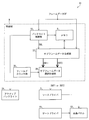
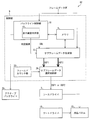
- 14 is a flowchart illustrating an example of the operation of the liquid crystal display device according to the fourth embodiment.
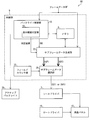
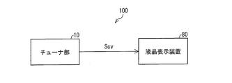
- FIG. 1 is a block diagram showing the configuration of the present liquid crystal display device.
- the present liquid crystal display device 80 includes an area active backlight (active backlight, backlight) 29, a liquid crystal panel 10, a gate driver 19, a source driver 3, and a control unit 9. .
- the liquid crystal panel 10 and each driver may be integrated.
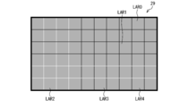
- the area active backlight 29 includes a plurality of illumination areas LAR, and each illumination area LAR is configured so that the amount of light per frame can be individually adjusted.
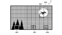
- the liquid crystal panel 10 includes a plurality of display areas HAR corresponding to the illumination areas LAR of the area active backlight 29 in the display unit.
- the display area HAR1 of the liquid crystal panel 10 corresponds to the illumination area LAR1 of the area active backlight 29.
- the control unit 9 of the present liquid crystal display device 80 includes a memory 6, a backlight control unit 15, a subframe data generation unit 22, a subframe data selection unit 25, and a field counter unit 35.
- the backlight control unit 15 includes a display luminance determination unit 16.
- Frame data (input data) DF is input to the backlight control unit 15 and the subframe data generation unit 22.
- the frame data DF is RGB data.
- the control unit 9 is provided with a timing control unit to which a vertical synchronization signal, a horizontal synchronization signal, a dot clock, and the like are input.
- the timing control unit includes the backlight control unit 15, It controls the subframe data generation unit 22, the subframe data selection unit 25, the gate driver 19, and the like.
- the backlight control unit 15 includes a maximum display luminance (maximum display luminance) and a minimum display luminance (minimum display luminance) assumed in the display area HAR from all the frame data DF included in each display area HAR. And the display luminance determination unit 16 determines whether or not the difference (luminance difference) between the maximum display luminance and the minimum display luminance is greater than a preset threshold (display luminance determination step). The display brightness determination unit 16 outputs the determination result to the subframe data generation unit 22.
- the threshold value is a value that serves as a reference for whether or not the brightness floats, and depends on the optical characteristics of the liquid crystal panel used and the optical system of the backlight, and is evaluated and determined in each system. Stored in the memory 6.
- the backlight control unit 15 determines the amount of light per frame of the illumination area LAR corresponding to the display area HAR based on the maximum display luminance (backlight control step), and uses this as data DBL as subframe data. Output to the generator 22. Further, the backlight control unit 15 adjusts (sets) the light amount per frame of the illumination area LAR based on the determined light amount (backlight control step). In the present liquid crystal display device 80, the illumination brightness of each illumination area LAR is fixed, and one frame of each illumination area LAR is changed by changing the light emission time in one frame period (that is, what percentage of one frame period is lit). Adjust the amount of light per unit.
- the subframe data generation unit 22 performs a process of generating subframe data based on the determination result of the display luminance determination unit 16 (frame data generation step). That is, when the difference between the minimum display brightness and the maximum display brightness (brightness difference) is larger than a preset threshold value, there is a high possibility that the brightness floats, so that the subframe display as shown in FIG. Subframe data (DSF1 and DSF2) is generated to perform the above. Specifically, the subframe data generation unit 22 generates the first subframe data based on the frame data DF and the light amount (data DBL) per frame of each illumination area LAR determined by the backlight control unit 15. DSF1 and second subframe data DSF2 are generated.
- the first subframe data DSF1 and the second subframe data DSF2 are generated so that the display luminances of the first subframe and the second subframe are different from each other.
- a subframe display is referred to as “luminance division subframe display”. That is, “luminance division subframe display” means that one frame is divided into a plurality of subframes (for example, the first subframe and the second subframe), and the luminance of each subframe is different from each other (that is, whichever This is a display method in which input data is displayed by the sum of the display of these subframes by concentrating the luminance on the subframe.
- the subframe data generation unit 22 performs processing for generating subframe data as follows based on the determination result of the display luminance determination unit 16 (frame data generation step). That is, the subframe data generation unit 22 performs the first subframe and the second subframe based on the frame data DF and the light amount (data DBL) per frame of each illumination area LAR determined by the backlight control unit 15. First subframe data DSF1 and second subframe data DSF2 are generated so that the display luminances of the frames are equal to each other.
- luminance equal subframe display means that one frame is divided into a plurality of subframes (for example, the first subframe and the second subframe), and the luminance of each subframe is equal to each other (that is, This means a display method in which input data is displayed by the sum of the display of these subframes without concentrating the luminance on the subframe.
- the first subframe data DSF1 and the second subframe data DSF2 generated by the subframe data generation unit 22 are input to the subframe data selection unit 25.
- the subframe data selection unit 25 performs a process of replacing the first and second subframe data DSF1 and DSF2 at double speed (for example, 120 Hz).
- the field counter unit 35 determines whether the timing is the timing of the first subframe or the timing of the second subframe, and outputs the determination result to the subframe data selection unit 25.
- the subframe data selection unit 25 Based on the determination result of the field counter unit 35, the subframe data selection unit 25 outputs the first subframe data DSF1 to the source driver 3 at the start timing of the first subframe and the first subframe data DSF1 at the start timing of the second subframe. 2 Subframe data DSF2 is output to the source driver 3.
- the source driver 3 converts the subframe data DSF1 and DSF2 into analog potential signals, and drives each source line (data signal line) of the liquid crystal panel 10 by this potential signal.
- the gate driver 19 drives a gate line (scanning signal line) of the liquid crystal panel 10 based on a known control signal output from the control unit 9.
- the “luminance division subframe” is displayed for the display area HAR.
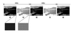
- FIG. 4 shows a state in which brightness floating (white floating) occurs in one frame. According to the configuration of the liquid crystal display device 80, “brightness division subframe display” is performed for the central display area HAR in which white floating occurs, and “brightness equal subframe display” is performed for the other display areas HAR. .
- FIG. 5 is a diagram showing a display state at every 120 Hz in the liquid crystal display device 80 when driving at 60 Hz per frame. As shown in this figure, it can be seen that the luminance difference between subframes is smaller than that in FIG. 25, and flicker is hardly recognized.
- FIG. 6 is a diagram for explaining a process of partially performing luminance division subframe display.
- A has shown the part (dotted line frame surrounding part) which a brightness
- B shows the state of the first half frame (first sub-frame) of one frame in a portion where the brightness is likely to rise. In the first subframe, the first subframe data DSF1 having low luminance is in a dark state.
- C) shows the state of the second half frame (second sub-frame) of one frame in the portion where the brightness is liable to occur. In the second subframe, a bright state is obtained by the second subframe data DSF2 having high luminance.
- D has shown the display state of 1 frame represented by the sum of the display of (b) and (c). As shown in (d), it can be seen that the luminance floating can be suppressed by partially performing the luminance division subframe display.
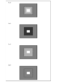
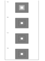
- Example 1 Hereinafter, specific examples (examples) will be described with reference to FIG. 2, FIG. 7 (a) to (c), FIG. 8, FIG. 9 (a), FIG. 9 (b), FIG. 10 (a) and FIG. 1) will be described.
- the backlight control unit 15 obtains the display brightness of the frame data DF in the display area HAR1.
- the display luminance of the moon portion is 80
- the display luminance of the wing portion of the airplane is 10
- the display luminance of the other portion is 60.
- the maximum display brightness is 80
- the minimum display brightness is 10
- the brightness difference is 70.
- the threshold value is set to 15
- the luminance difference (70) is larger than the threshold value (15), so that “luminance division subframe display” is performed in the display area HAR1.
- the backlight control unit 15 determines the amount of light per frame of the illumination area LAR1 as 80. That is, the backlight control unit 15 sets the light emission time of the illumination area LAR1 to 0.8 frames, sets the light emission state for the 0.2 frame period from the start of the frame, and sets the light emission state for the remaining 0.8 frame period. To do.
- the subframe data generation unit 22 performs processing for generating subframe data (DSF1 and DSF2) based on the determination result of the display luminance determination unit 16 (luminance difference (70)> threshold (15)). That is, the first subframe data DSF1 and the second subframe data DSF2 are generated based on the setting of the backlight control unit 15 (light quantity 80) and the frame data DF. This is schematically shown in FIGS. 7 (a) to (c).
- the subframe data generation unit 22 uses the first subframe data DSF1 indicating the light transmittance of 100% for the month portion (the portion where the assumed display luminance is 80) in the display area HAR1.
- Second subframe data DSF2 indicating 100% light transmittance is generated.
- the display luminance is 0 even if the light transmittance on the display area HAR1 side is set to 100%.
- the display luminance is 100 if the light transmittance on the display area HAR1 side is 100%. If this is represented schematically, it will be understood that the configuration of the present application shown in FIG. 7A can be obtained, and sub-frame display can be performed while suppressing the amount of light in the illumination area LAR1.
- the subframe data generation unit 22 performs the first subframe indicating the light transmittance of 33% for the empty portion (the portion where the assumed display luminance is 60) in the display area HAR1.
- Data DSF1 and second subframe data DSF2 indicating 100% light transmittance are generated.
- the illumination area LAR1 is in a non-light emitting state during the 0.2 frame period from the start of the frame, the display luminance is 0 even if the light transmittance on the display area HAR1 side is set to 33%.
- the display luminance is 33 if the light transmittance on the display area HAR1 side is 33%, and the display luminance if the light transmittance is 100%. Is also 100. If this is schematically represented, it can be seen that the present application configuration of FIG. 7B is obtained, and sub-frame display can be performed while suppressing the amount of light in the illumination area LAR1.
- the subframe data generation unit 22 performs the first subframe indicating 0% light transmittance for the wing portion (the portion where the assumed display luminance is 10) in the display area HAR1.
- Data DSF1 and second subframe data DSF2 indicating 20% light transmittance are generated.
- the illumination area LAR1 is in a non-light emitting state (the light transmittance on the display area HAR1 side is also 0%) during the 0.2 frame period from the start of the frame, the display luminance is zero.
- the display luminance is 0 if the light transmittance on the display area HAR1 side is 0 percent, and the display luminance if the light transmittance is 20 percent. Will also be 20. If this is represented schematically, it will be understood that the present application configuration of FIG. 7C is obtained, and sub-frame display can be performed while suppressing the amount of light in the illumination area LAR1.
- the illumination area LAR1 is in a non-light emitting state in the first half (0.2 frame period), there is no light leakage and the display luminance can be reliably reduced to zero.
- the display area HAR2 in FIG. 2 is a solid (black) display, and the assumed maximum display brightness is zero.
- the backlight control unit 15 determines the light amount per frame in the illumination area LAR2 to be 0. That is, the backlight control unit 15 is always in a non-light emitting state during the frame period.
- the subframe data generation unit 22 generates the first subframe data DSF1 and the second subframe data DSF2 based on the setting (light quantity 0) of the backlight control unit 15 and the frame data DF of the display area HAR2. This is schematically shown in FIG.
- the subframe data generation unit 22 includes the first subframe data DSF1 indicating the light transmittance of 0% and the light transmittance of 0 for the display area HAR2 (the portion where the assumed display luminance is 0). Second subframe data DSF2 indicating the percentage is generated. If this is represented schematically, it will be understood that the configuration of the present application shown in FIG.
- the display area HAR3 in FIG. 2 will be described with reference to FIGS. 9 (a) and 9 (b).
- the display luminance of the background portion of the tree is 40 and the display luminance of the tree portion is 20.
- the maximum display brightness is 40
- the minimum display brightness is 20, and the brightness difference is 20.
- the threshold value is set to 15
- the luminance difference (20) is larger than the threshold value (15)
- “luminance division subframe display” is performed in the display area HAR3.
- the backlight control unit 15 determines the amount of light per frame in the illumination area LAR3 as 40. That is, the backlight control unit 15 sets the light emission time of the illumination area LAR3 to 0.4 frames, sets the light emission state for the 0.6 frame period from the start of the frame, and sets the light emission state for the remaining 0.4 frame period. To do.
- the subframe data generation unit 22 performs processing for generating subframe data (DSF1 and DSF2) based on the determination result of the display luminance determination unit 16 (luminance difference (20)> threshold (15)). That is, the first subframe data DSF1 and the second subframe data DSF2 are generated based on the setting of the backlight control unit 15 (light quantity 40) and the frame data DF. This is schematically shown in FIGS. 9 (a) and 9 (b).
- the subframe data generation unit 22 performs the first subframe that indicates 0% light transmittance for the background portion of the tree in the display area HAR3 (the portion where the assumed display luminance is 40).
- Data DSF1 and second subframe data DSF2 indicating 100% light transmittance are generated.
- the display luminance is zero.
- the display luminance is 100 if the light transmittance on the display area HAR3 side is 100%.
- the first subframe data DSF1 indicating the light transmittance of 0% and the light transmittance Second subframe data DSF2 indicating 50 percent is generated.
- the illumination area LAR3 is in a non-light emitting state during the 0.6 frame period from the start of the frame (the light transmittance on the display area HAR3 side is also 0)
- the display luminance is zero.
- the illumination area LAR3 is in a light emitting state during the remaining 0.4 frame period, if the light transmittance on the display area HAR3 side is 50%, the display luminance is also 50%.
- the display area HAR4 in FIG. 2 will be described with reference to FIGS. 10 (a) and 10 (b).
- the display brightness of the background portion of the house is 80 and the display brightness of the house portion is 70.
- the maximum display brightness is 80
- the minimum display brightness is 70
- the brightness difference is 10.
- the threshold value is set to 15
- the luminance difference (10) is equal to or smaller than the threshold value (15), so that “luminance equal subframe display” is performed in the display area HAR4.
- the backlight control unit 15 determines the light amount per frame of the illumination area LAR4 as 80. That is, the backlight control unit 15 sets the light emission time of the illumination area LAR4 to 0.8 frames, sets the light emission state for the 0.2 frame period from the start of the frame, and sets the light emission state for the remaining 0.8 frame period. To do.
- the subframe data generation unit 22 performs processing for generating subframe data (DSF1 and DSF2) based on the determination result of the display luminance determination unit 16 (luminance difference (10) ⁇ threshold (15)). That is, the first subframe data DSF1 and the second subframe data DSF2 are generated based on the setting of the backlight control unit 15 (light quantity 80) and the frame data DF. This is schematically shown in FIGS. 10 (a) and 10 (b).
- the subframe data generation unit 22 performs the first subframe indicating the light transmittance of 100% for the background portion of the house in the display area HAR4 (the portion where the assumed display luminance is 80).
- Data DSF1 and second subframe data DSF2 indicating 100% light transmittance are generated.
- the display brightness is 0 even if the light transmittance on the display area HAR4 side is set to 100%.
- the display luminance is 100 if the light transmittance on the display area HAR4 side is 100%. If this is represented schematically, it will be understood that the configuration of the present application shown in FIG.
- the subframe data generation unit 22 has a first light transmittance of 87.5% for the house portion (the portion where the assumed display luminance is 70) in the display area HAR4.
- Subframe data DSF1 and second subframe data DSF2 indicating light transmittance of 87.5% are generated.
- the illumination area LAR4 is in a non-light emitting state during the 0.2 frame period from the start of the frame, the display luminance is 0 even if the light transmittance on the display area HAR4 side is set to 87.5%.
- the illumination area LAR4 is in a light emitting state during the remaining 0.8 frame period, if the light transmittance on the display area HAR4 side is 87.5%, the display luminance is 87.5. If this is schematically shown, it becomes the present application configuration of FIG. 10B, and it can be seen that sub-frame display can be performed while suppressing the amount of light in the illumination area LAR4.
- the illumination area LARn is set to the non-light-emitting state during (100 ⁇ Rmax) ⁇ 100 frame period from the start of one frame period, and the remaining Rmax ⁇ 100 frame period is the illumination area. LARn emits light (continuously).
- the first subframe indicating the light transmittance of 0% with the light amount of the illumination area LARn being 40.
- the first subframe data indicating the light transmittance of 0% with the light amount of the illumination area LARn being 80.
- the light transmittance X (display brightness assumed by the input data ⁇ 50) ⁇ (Rmax ⁇ 50) ⁇ 100) is generated, and second subframe data DSF2 indicating 100% light transmittance is generated.
- the illumination area LARn is set to the non-light emission state during the 0.2 frame period, and the illumination area LARn is emitted (continuously) during the remaining 0.8 frame period.
- Example 2 Next, another specific example (Example 2) will be described with reference to FIGS. 2, 26A to 26C, FIG. 27A, and FIG. 27B.
- the configuration in which the light emission time is assigned to the second half frame (second subframe), that is, the light emission time of the set illumination area LAR1 (0.8 frames in FIG. 7) is 0.2 frame period from the start of the frame. Is in a non-light emitting state, and the remaining 0.8 frame period is in a light emitting state.
- the light emission time (0.8 frames) of the set illumination area LAR1 is equally allocated in one frame for display.
- the display area HAR1 in FIG. 2 will be described with reference to FIGS.
- the backlight control unit 15 obtains the display brightness of the frame data DF in the display area HAR1.
- the display brightness of the moon portion is 80
- the display brightness of the wing portion of the airplane is 10
- the display brightness of the other portion is 60.
- the maximum display brightness is 80
- the minimum display brightness is 10
- the brightness difference is 70.
- the threshold value is set to 15
- the luminance difference (70) is larger than the threshold value (15), so that “luminance division subframe display” is performed in the display area HAR1.
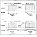
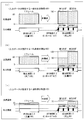
- the backlight control unit 15 determines the amount of light per frame of the illumination area LAR1 as 80. That is, the backlight control unit 15 assigns the light emission time of the illumination area LAR1 evenly in one frame. For example, the 0.05 frame period from the start of the frame is set to the non-light emitting state, the next 0.2 frame period is set to the light emitting state, and this is repeated for the remaining frame periods. As a result, in the entire frame, the non-light emission period of the 0.05 frame period is 4 blocks, the light emission period of the 0.2 frame period is 4 blocks, and the total 0.2 frame period is in the non-light emission state. Eight frames are in the light emission state. In each subframe, the non-light emission period of 0.05 frame period is 2 blocks and the light emission period of 0.2 frame period is 2 blocks, and the light emission time of each subframe is equally 0.4 frames.
- the subframe data generation unit 22 performs processing for generating subframe data (DSF1 and DSF2) based on the determination result of the display luminance determination unit 16 (luminance difference (70)> threshold (15)). That is, the first subframe data DSF1 and the second subframe data DSF2 are generated based on the setting of the backlight control unit 15 (light quantity 80) and the frame data DF. This is schematically shown in FIGS. 26 (a) to 26 (c).
- the subframe data generation unit 22 uses the first subframe data DSF1 indicating the light transmittance of 100% for the month portion (the portion where the assumed display luminance is 80) in the display area HAR1.
- Second subframe data DSF2 indicating 100% light transmittance is generated.
- the illumination area LAR1 is in a non-light emitting state during the 0.05 frame period from the start of the frame, the display brightness is 0 even if the light transmittance on the display area HAR1 side is set to 100%.
- the display luminance is also 100.
- the display luminance is 0, and during the next 0.2 frame period, the display area is 100 because the illumination area LAR1 is in a light emitting state.
- the light transmittance on the display area HAR1 side is 100. Even if the percentage is set, the display brightness is 0, and the illumination area LAR1 is in the light emission state during the next 0.2 frame period. Therefore, if the light transmittance on the display area HAR1 side is 100%, the display brightness is 100. Become.
- the display luminance is 0, and during the next 0.2 frame period, the display area is 100 because the illumination area LAR1 is in a light emitting state. Become. If this is schematically shown, it can be seen that the configuration of the present application shown in FIG. 26A is obtained, and subframe display can be performed while suppressing the amount of light in the illumination area LAR1.
- the subframe data generation unit 22 performs the first subframe indicating the light transmittance of 50% for the empty portion (the portion where the assumed display luminance is 60) in the display area HAR1.
- Data DSF1 and second subframe data DSF2 indicating 100% light transmittance are generated.
- the display luminance is 0 even if the light transmittance on the display area HAR1 side is set to 50%.
- the display luminance is also 50.
- the display luminance is 0, and since the illumination area LAR1 is in the light emitting state during the next 0.2 frame period, the display luminance is 50. Obviously, since the illumination area LAR1 is in the non-light emitting state during the next 0.05 frame period, the display luminance is 0, and since the illumination area LAR1 is in the light emitting state during the next 0.2 frame period, the display luminance is 50. Obviously, since the illumination area LAR1 is in the non-light emitting state during the next 0.05 frame period, the display luminance is 0, and since the illumination area LAR1 is in the light emitting state during the next 0.2 frame period, the display luminance is 50. Become.
- the light transmittance on the display area HAR1 side is set to 100% because the illumination area LAR1 is in a non-light-emitting state for 0.05 frame period from the start (after the lapse of 0.5 frame period from the start of the frame). Even if the display area is displayed, the display brightness is 0, and the illumination area LAR1 is in a light emitting state during the next 0.2 frame period. Therefore, if the light transmittance on the display area HAR1 side is 100%, the display brightness is also 100.
- the display luminance is 0, and during the next 0.2 frame period, the display area is 100 because the illumination area LAR1 is in a light emitting state. Become. If this is schematically shown, the present application configuration of FIG. 26B is obtained, and it can be seen that sub-frame display can be performed while suppressing the amount of light in the illumination area LAR1.
- the subframe data generation unit 22 performs the first subframe indicating 0% light transmittance for the wing portion (the portion where the assumed display luminance is 10) in the display area HAR1.
- Data DSF1 and second subframe data DSF2 indicating a light transmittance of 25% are generated.
- the illumination area LAR1 is in a non-light emitting state (the light transmittance on the display area HAR1 side is also 0%) during the 0.05 frame period from the start of the frame, the display luminance is zero.
- the illumination area LAR1 is in a light emitting state, if the light transmittance on the display area HAR1 side is 0%, the display luminance is also zero.
- the illumination area LAR1 is in a non-light emitting state during the next 0.05 frame period, the display luminance is 0, and during the next 0.2 frame period, the illumination area LAR1 is in a light emitting state, but the display luminance is 0. Obviously, since the illumination area LAR1 is in a non-light emitting state during the next 0.05 frame period, the display luminance is 0, and during the next 0.2 frame period, the illumination area LAR1 is in a light emitting state, but the display luminance is 0. Become.
- the light transmittance on the display area HAR1 side is set to 25% because the illumination area LAR1 is in a non-light-emitting state for 0.05 frame period from the start (after the lapse of 0.5 frame period from the start of the frame). Even if the display area is displayed, the display brightness is 0, and the illumination area LAR1 is in a light emitting state during the next 0.2 frame period. Therefore, if the light transmittance on the display area HAR1 side is 25%, the display brightness is 25.
- the display luminance is 0, and during the next 0.2 frame period, the display area is 25 because the illumination area LAR1 is in the light emitting state. Become. If this is schematically shown, the present application configuration of FIG. 26C is obtained, and it can be seen that sub-frame display can be performed while suppressing the amount of light in the illumination area LAR1.
- luminance division subframe display can be performed in the same manner as described above.
- the luminance difference (10) is equal to or less than the threshold value (15), so that “luminance uniform subframe display” is performed.
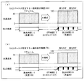
- luminance uniform subframe display in the second embodiment will be described with reference to FIGS. 27A and 27B.
- the backlight control unit 15 determines the light amount per frame of the illumination area LAR4 as 80. That is, the backlight control unit 15 assigns the light emission time of the illumination area LAR4 evenly in one frame. For example, the 0.05 frame period from the start of the frame is set to the non-light emitting state, the next 0.2 frame period is set to the light emitting state, and this is repeated for the remaining frame periods. As a result, in the entire frame, the non-light emission period of the 0.05 frame period is 4 blocks, the light emission period of the 0.2 frame period is 4 blocks, and the total 0.2 frame period is in the non-light emission state. Eight frames are in the light emission state. In each subframe, the non-light emission period of 0.05 frame period is 2 blocks and the light emission period of 0.2 frame period is 2 blocks, and the light emission time of each subframe is equally 0.4 frames.
- the subframe data generation unit 22 performs processing for generating subframe data (DSF1 and DSF2) based on the determination result of the display luminance determination unit 16 (luminance difference (10) ⁇ threshold (15)). That is, the first subframe data DSF1 and the second subframe data DSF2 are generated based on the setting of the backlight control unit 15 (light quantity 80) and the frame data DF. This is schematically shown in FIGS. 27 (a) and 27 (b).
- the subframe data generation unit 22 performs the first subframe indicating the light transmittance of 100% for the background portion of the house in the display area HAR4 (the portion where the assumed display luminance is 80).
- Data DSF1 and second subframe data DSF2 indicating 100% light transmittance are generated.
- the display luminance is 0 even if the light transmittance on the display area HAR4 side is set to 100%.
- the display luminance is also 100.
- the display luminance is 0, and during the next 0.2 frame period, the display area is 100 because the illumination area LAR4 is in a light emitting state.
- the light transmittance on the display area HAR4 side is 100. Even if the percentage is set, the display brightness is 0, and the illumination area LAR4 is in a light emitting state during the next 0.2 frame period. Therefore, if the light transmittance on the display area HAR4 side is 100%, the display brightness is 100. Become.
- the display luminance is 0, and during the next 0.2 frame period, the display area is 100 because the illumination area LAR4 is in a light emitting state. Become. If this is represented schematically, it will be understood that the configuration of the present application shown in FIG. 27A can be obtained, and sub-frame display can be performed while suppressing the amount of light in the illumination area LAR4.
- the subframe data generation unit 22 has a first light transmittance of 87.5% for the house portion (the portion where the assumed display luminance is 70) in the display area HAR4.
- Subframe data DSF1 and second subframe data DSF2 indicating light transmittance of 87.5% are generated.
- the illumination area LAR4 is in a non-light emitting state during the 0.05 frame period from the start of the frame, the display luminance is 0 even if the light transmittance on the display area HAR4 side is set to 87.5%.
- the display luminance is also 87.5. Since the illumination area LAR4 is in a non-light emitting state during the next 0.05 frame period, the display luminance is 0. In the next 0.2 frame period, since the illumination area LAR4 is in a light emitting state, the display luminance is 87.degree. 5
- the light transmittance on the display area HAR4 side is 87. Even if it is set to .5%, the display brightness is 0, and the illumination area LAR4 is in a light emitting state during the next 0.2 frame period. Therefore, if the light transmittance on the display area HAR4 side is 87.5%, the display is performed.
- the luminance is also 87.5. Since the illumination area LAR4 is in a non-light emitting state during the next 0.05 frame period, the display luminance is 0.
- the display luminance is 87.degree. 5 If this is represented schematically, it will be understood that the present application configuration of FIG. 27B is obtained, and sub-frame display can be performed while suppressing the amount of light in the illumination area LAR4.
- the maximum display luminance assumed in the display area HARn is Rmax
- the illumination area LARn is set to the non-light emitting state during (100 ⁇ Rmax) ⁇ 100 frame periods in one frame period, and the illumination area LARn is caused to emit light during the remaining Rmax ⁇ 100 frame periods. Note that the non-light emitting state period and the light emitting state period are equally allocated in one frame period.
- the maximum display luminance assumed in the display area HARn is 80 and the display luminance assumed in the input data is 60%
- the light amount in the illumination area LARn is 80
- first subframe data DSF1 indicating percent and second subframe data DSF2 indicating light transmittance of 100 percent are generated.
- the illumination area LARn is caused to emit light. For example, from the start of one frame period, the 0.05 frame period is set to the non-light emitting state, the next 0.2 frame period is set to the light emitting state, and this is repeated thereafter (see FIG. 26B).
- the maximum display luminance assumed in the display area HARn is Rmax
- the display luminance assumed by the input data ⁇ (Rmax / 2) the light quantity of the corresponding illumination area is Rmax, and each input data
- the first subframe data DSF1 indicating the light transmittance of 0%
- the second subframe indicating the light transmittance X (display luminance assumed by the input data ⁇ (Rmax ⁇ 2)) ⁇ 100) percent.
- Data DSF2 is generated.
- the first subframe indicating the light transmittance of 0% with the light amount of the illumination area LARn being 80.
- the illumination area LARn is caused to emit light. For example, from the start of one frame period, the 0.05 frame period is set to the non-light emitting state, the next 0.2 frame period is set to the light emitting state, and this is repeated thereafter (see FIG. 26C).
- the present liquid crystal display device may have the following configuration.
- the first subframe of the first half of one frame is set to a non-light emitting state or low display brightness
- the second subframe of the second half is set to high display brightness
- the present invention is not limited to this. Instead, the first subframe of the first half may be set to high display luminance, and the second subframe of the second half may be set to a non-light emitting state or low display luminance.
- the backlight control unit 15 determines the amount of light per frame of the illumination area LAR, but it is preferable to consider the influence of crosstalk in this determination.
- the amount of backlight light is changed for each illumination area, the light that illuminates a display area is included in the light that illuminates a display area due to crosstalk between illumination areas (wrapping of illumination light from adjacent display areas). The phenomenon of being degenerated occurs. Therefore, the backlight control unit 15 once obtains the light amount per frame of each illumination area LAR from the maximum display luminance assumed in each display area HAR, and further, based on the light amount of the adjacent display area. The amount of light in the illumination area LAR is finally determined.
- the light quantity of each illumination area LAR once obtained is corrected using a LUT (Looking Up Table).
- LUT Light amount correction data is stored according to the combination of the light amount of the target illumination area and the light amount of the illumination area adjacent thereto.
- the backlight control unit 15 outputs the finally determined light amount to the subframe data generation unit 22 as data DBL.
- the R, G, B LEDs can be used for the area active backlight 29.
- the light amount per frame of each illumination area LAR is determined for each of R, G, and B from the maximum display luminance (R, G, B) assumed in each display area HAR.
- the subframe data generation unit 22 performs the first subframe data DSF1 and the second subframe based on the determined light amounts of R, G, and B and the frame data DF (R, G, B data). Data DSF2 is generated.
- Embodiment 2 Another embodiment of the liquid crystal display device according to the present invention will be described below. For convenience of explanation, members having the same functions as those shown in the first embodiment are given the same reference numerals. In addition, the terms defined in Embodiment 1 are used in accordance with the definitions in this embodiment unless otherwise specified.
- FIG. 11 is a block diagram showing the configuration of the present liquid crystal display device.
- the present liquid crystal display device 81 includes an area active backlight (active backlight, backlight) 29, a liquid crystal panel 10, a gate driver 19, a source driver 3, and a control unit 9. .
- the liquid crystal panel 10 and each driver may be integrated.
- the area active backlight 29 includes a plurality of illumination areas LAR, and each illumination area LAR is configured so that the amount of light per frame can be individually adjusted.
- the liquid crystal panel 10 includes a plurality of display areas HAR corresponding to the illumination areas LAR of the area active backlight 29 in the display unit.
- the display area HAR1 of the liquid crystal panel 10 corresponds to the illumination area LAR1 of the area active backlight 29.
- the control unit 9 of the present liquid crystal display device 81 includes a memory 6, a backlight control unit 15, a subframe data generation unit 22, a subframe data selection control unit 26, and a field counter unit 35.
- Frame data (input data) DF is input to the backlight control unit 15 and the subframe data generation unit 22.
- the frame data DF is RGB data.
- the control unit 9 is provided with a timing control unit to which a vertical synchronization signal, a horizontal synchronization signal, a dot clock, and the like are input.
- the timing control unit includes the backlight control unit 15, It controls the subframe data generation unit 22, the subframe data selection control unit 26, the gate driver 19, and the like.
- the backlight control unit 15 obtains the maximum display luminance assumed in the display area HAR from all the frame data DF included in each display area HAR, and based on this, the illumination area corresponding to the display area HAR The amount of light per frame of LAR is determined, and this is output to the subframe data generation unit 22 as data DBL. Further, the backlight control unit 15 adjusts (sets) the light amount per frame of the illumination area LAR based on the determined light amount. In the present liquid crystal display device 81, the illumination brightness of each illumination area LAR is made constant, and the light emission time in one frame period (that is, what percentage of one frame period is lit) is changed to change one frame of each illumination area LAR. Adjust the amount of light per unit.
- the subframe data generation unit 22 is based on the frame data DF and the light amount (data DBL) per frame of each illumination area LAR determined by the backlight control unit 15 in order to perform the “luminance division subframe display”. Thus, the first subframe data DSF1 and the second subframe data DSF2 are generated.
- the first subframe data DSF1 and the second subframe data DSF2 generated by the subframe data generation unit 22 are input to the subframe data selection control unit 26, and in the subframe data selection control unit 26, the first and second subframe data DSF1 are generated.
- the two subframe data DSF1 and DSF2 are switched at a double speed (for example, 120 Hz).
- the field counter unit 35 determines whether the timing is the first subframe timing or the second subframe timing, and outputs the determination result to the subframe data selection control unit 26.
- the subframe data selection control unit 26 outputs the first subframe data DSF1 to the source driver 3 at the start timing of the first subframe based on the determination result of the field counter unit 35, and the start timing of the second subframe. Then, the second subframe data DSF 2 is output to the source driver 3.
- the source driver 3 converts each subframe data (DSF1 and DSF2) into an analog potential signal, and drives each source line (data signal line) of the liquid crystal panel 10 by this potential signal.
- the gate driver 19 drives a gate line (scanning signal line) of the liquid crystal panel 10.
- the method of setting the amount of light per frame of the illumination area LAR and the method of generating the first subframe data DSF1 and the second subframe data DSF2 performed in the subframe data generation unit 22 are the same as in the first embodiment. Since there is, explanation is omitted.
- the output method of the first subframe data DSF1 and the second subframe data DSF2 generated by the subframe data generation unit 22 to the source driver 3 will be described below together with the specific configuration of the subframe data selection control unit 26.
- the subframe data having the lower display luminance is the dark subframe data
- the subframe data having the higher display luminance is the bright subframe data. Called.
- the subframe data selection control unit 26 replaces the dark subframe data and the bright subframe data for each frame, and outputs them to the source driver 3.
- dark subframe data is output to the source driver 3 at the start timing of the first subframe
- bright subframe data is output to the source driver 3 at the start timing of the second subframe.
- dark subframe data is output to the source driver 3 at the start timing of the second subframe.
- dark subframe data is output to the source driver 3 again at the start timing of the first subframe
- bright subframe data is output to the source driver 3 at the start timing of the second subframe. Thereafter, this process is repeated.
- the subframe data selection control unit 26 outputs to the source driver 3 so that the dark subframe data and the bright subframe data differ from each other in a staggered manner in adjacent pixels.
- the first pixel outputs dark subframe data to the source driver 3 at the start timing of the first subframe. Then, the bright subframe data is output to the source driver 3 at the start timing of the second subframe. In the second pixel, the bright subframe data is output to the source driver 3 at the start timing of the first subframe, and the dark subframe data is output to the source driver 3 at the start timing of the second subframe.
- the sub-frame data selection control unit 26 replaces the dark sub-frame data and the bright sub-frame data for each frame, so that the second frame is as follows.
- the first pixel outputs bright subframe data to the source driver 3 at the start timing of the first subframe, and outputs dark subframe data to the source driver 3 at the start timing of the second subframe.
- dark subframe data is output to the source driver 3 at the start timing of the first subframe
- bright subframe data is output to the source driver 3 at the start timing of the second subframe.
- the dark subframe data and the bright subframe data are switched for each frame.
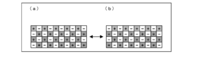
- FIG. 12 schematically shows a driving method of each pixel of the liquid crystal panel 10.
- A shows the driving method of each pixel of odd frames (first frame, third frame, fifth frame, etc, And
- (b) shows even frames (second frame, fourth frame, sixth frame). ,...)).
- the shaded portion is a pixel whose luminance increases in the second half (second subframe) of one frame (that is, dark subframe data is output in the first subframe, and bright subframe data is output in the second subframe.
- a pixel whose luminance is high that is, bright subframe data is output in the first subframe and the second subpixel is output).
- FIG. 12 shows dot inversion driving in which polarities differ between adjacent pixels, the driving method is not limited to this.
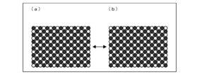
- FIG. 13 is a diagram visually representing a driving method of each pixel of the liquid crystal panel 10 corresponding to FIG. 12, and FIG. 13A is an odd-numbered frame (first frame, third frame, fifth frame,). (B) shows even frames (second frame, fourth frame, sixth frame,).
- black indicates a pixel whose luminance increases in the second half of one frame
- white indicates a pixel whose luminance increases in the first half of one frame.
- FIG. 13 it can be seen that it is difficult to recognize the luminance difference when the frames are switched.
- FIG. 14 is a diagram showing a display state for each 120 Hz (subframe) in the liquid crystal display device when driving at 60 Hz per frame.
- the luminance difference between the subframes is smaller than that of the conventional configuration (see FIG. 25), and flicker is hardly recognized.
- the average value of the display luminance (brightness and darkness) of the entire display surface of the display panel (the display surface on the left side of each frame (60 Hz) shown in FIG. 14) in the first half frame and the second half
- the difference between the display panel display surface (the display surface on the right side of each frame (60 Hz)) in the frame and the average value of the display luminance (brightness and darkness) of the entire display panel is the above-mentioned “luminance division subframe display” on the entire display surface of the display panel. This is smaller than the case (see FIG. 25), and it is difficult to recognize the luminance difference between subframes.
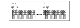
- the method of allocating the dark subframe data and the bright subframe data is not limited to the configuration shown in FIG. 12, and the dark subframe data and the bright subframe data are set for each set with two adjacent pixels as one set. May be different.
- the dark subframe data and the bright subframe data are set for each set with two adjacent pixels as one set. May be different.
- FIG. 15A in the first frame (FIG. 15A), in the first set, bright subframe data is output in the first subframe and dark subframes are output in the second subframe.
- Frame data is output, and in the second set, dark subframe data is output in the first subframe, and bright subframe data is output in the second subframe.
- the second frame ((b) of FIG.
- dark subframe data is output in the first subframe
- bright subframe data is output in the second subframe
- Bright subframe data is output in one subframe
- dark subframe data is output in a second subframe.
- Embodiment 3 Another embodiment of the liquid crystal display device according to the present invention will be described below.
- members having the same functions as those shown in the first and second embodiments are given the same reference numerals.
- the terms defined in Embodiments 1 and 2 are used in accordance with the definitions in this embodiment unless otherwise specified.
- the liquid crystal display device of the present embodiment includes the characteristic configurations of the first and second embodiments.
- the present liquid crystal display device is configured to perform the process of making the dark subframe and the bright subframe different between adjacent pixels only in a display area having a large luminance difference.
- FIG. 16 is a block diagram showing the configuration of the present liquid crystal display device.
- the present liquid crystal display device 82 includes an area active backlight (active backlight) 29, a liquid crystal panel 10, a gate driver 19, a source driver 3, and a control unit 9.
- the liquid crystal panel 10 and each driver may be integrated.
- the area active backlight 29 includes a plurality of illumination areas LAR, and each illumination area LAR is configured so that the amount of light per frame can be individually adjusted.
- the liquid crystal panel 10 includes a plurality of display areas HAR corresponding to the illumination areas LAR of the area active backlight 29 in the display unit.
- the display area HAR1 of the liquid crystal panel 10 corresponds to the illumination area LAR1 of the area active backlight 29.
- the control unit 9 of the present liquid crystal display device 82 includes a memory 6, a backlight control unit 15, a subframe data generation unit 22, a subframe data selection control unit 26, and a field counter unit 35.
- the backlight control unit 15 includes a display luminance determination unit 16.
- Frame data (input data) DF is input to the backlight control unit 15 and the subframe data generation unit 22.
- the frame data DF is RGB data.
- the control unit 9 is provided with a timing control unit to which a vertical synchronization signal, a horizontal synchronization signal, a dot clock, and the like are input.
- the timing control unit includes the backlight control unit 15, It controls the subframe data generation unit 22, the subframe data selection control unit 26, the gate driver 19, and the like.
- the backlight control unit 15 includes a maximum display luminance (maximum display luminance) and a minimum display luminance (minimum display luminance) assumed in the display area HAR from all the frame data DF included in each display area HAR.
- the display luminance determination unit 16 determines whether or not the difference (luminance difference) between the maximum display luminance and the minimum display luminance is larger than a preset threshold value.
- the display brightness determination unit 16 outputs the determination result to the subframe data generation unit 22.
- the threshold value is a value that serves as a reference for whether or not the brightness floats, and depends on the optical characteristics of the liquid crystal panel used and the optical system of the backlight, and is evaluated and determined in each system. Stored in the memory 6.
- the backlight control unit 15 determines the amount of light per frame of the illumination area LAR corresponding to the display area HAR based on the maximum display luminance, and outputs this to the subframe data generation unit 22 as data DBL. . Further, the backlight control unit 15 adjusts (sets) the light amount per frame of the illumination area LAR based on the determined light amount.
- the illumination brightness of each illumination area LAR is made constant, and the light emission time in one frame period (that is, what percentage is lit in one frame period) is changed to change 1 of each illumination area LAR. Adjust the amount of light per frame.
- the subframe data generation unit 22 performs a process of generating subframe data based on the determination result of the display luminance determination unit 16. That is, when the difference between the minimum display brightness and the maximum display brightness (brightness difference) is larger than a preset threshold value, there is a high possibility that the brightness will rise, so the “brightness division subframe display” is performed. Therefore, the first subframe data DSF1 and the second subframe data DSF2 are generated based on the frame data DF and the light amount (data DBL) per frame of each illumination area LAR determined by the backlight control unit 15. .
- the first subframe data DSF1 and the second subframe data DSF2 generated by the subframe data generation unit 22 are input to the subframe data selection control unit 26.
- the subframe data selection control unit 26 performs a process of replacing the first and second subframe data DSF1 and DSF2 at a double speed (for example, 120 Hz).
- the field counter unit 35 determines whether the timing is the first subframe timing or the second subframe timing, and outputs the determination result to the subframe data selection control unit 26.
- the subframe data selection control unit 26 outputs the first subframe data DSF1 to the source driver 3 at the start timing of the first subframe based on the determination result of the field counter unit 35, and the start timing of the second subframe. Then, the second subframe data DSF 2 is output to the source driver 3. In addition, the subframe data selection control unit 26 replaces the dark subframe data and the bright subframe data for each frame and outputs them to the source driver 3. For example, in the first frame, dark subframe data is output to the source driver 3 at the start timing of the first subframe, and bright subframe data is output to the source driver 3 at the start timing of the second subframe. In the second frame, bright subframe data is output to the source driver 3 at the start timing of the first subframe, and dark subframe data is output to the source driver 3 at the start timing of the second subframe.
- the source driver 3 converts each subframe data (DSF1 and DSF2) into an analog potential signal, and drives each source line (data signal line) of the liquid crystal panel 10 by this potential signal.
- the gate driver 19 drives a gate line (scanning signal line) of the liquid crystal panel 10.
- the method of setting the amount of light per frame of the illumination area LAR and the method of generating the first subframe data DSF1 and the second subframe data DSF2 performed in the subframe data generation unit 22 are the same as in the first embodiment. Since there is, explanation is omitted. Further, the method for outputting the first subframe data DSF1 and the second subframe data DSF2 generated by the subframe data generation unit 22 to the source driver 3 is the same as that in the second embodiment, and thus the description thereof is omitted.
- the dark sub-frame and the bright subframe are not subjected to a process of differentiating between adjacent pixels.
- FIG. 17 is a diagram for explaining processing for partially performing “luminance division subframe display” and processing for making dark subframes and bright subframes different between adjacent pixels.
- A has shown the part which a brightness
- B shows the state of the first half frame (first sub-frame) of one frame in a portion where the brightness is likely to rise.
- (C) shows the state of the second half frame (second sub-frame) of one frame in the portion where the brightness is liable to occur.
- the subframe data with low luminance and the subframe data with high luminance are arranged in a staggered manner so that they differ between adjacent pixels. Therefore, the luminance is averaged over the entire display surface. Therefore, as shown in (b) and (c) of FIG. 6, it is difficult to recognize each subframe as a dark state or a bright state.
- (D) has shown the display state of 1 frame represented by the sum of the display of (b) and (c).
- by performing “luminance division subframe display” partially and processing for making dark subframes and bright subframes different between adjacent pixels, it is possible to suppress luminance floating. I understand.
- the present liquid crystal display device 82 it is possible to make it difficult to recognize the luminance difference between subframes as compared to the configurations of the first and second embodiments.
- Embodiment 4 Another embodiment of the liquid crystal display device according to the present invention will be described below.
- members having the same functions as those shown in the first to third embodiments are given the same reference numerals.
- the terms defined in Embodiments 1 to 3 are used in accordance with the definitions in this embodiment unless otherwise specified.
- the liquid crystal display device of this embodiment has a function of switching each driving method shown in Embodiments 1 to 3 to each other.
- the driving method described in the first embodiment that is, driving in which “luminance division subframe display” is performed only in a display area in which luminance is likely to occur
- driving mode A driving in which “luminance division subframe display” is performed only in a display area in which luminance is likely to occur
- driving mode B driving in which a dark subframe and a bright subframe are different between adjacent pixels
- driving method shown in the third embodiment that is, the dark subframe and the bright subframe are represented by The process of making the pixel different between adjacent pixels is called “driving mode C”. That is, the present liquid crystal display device is configured to switch the drive modes A to C based on the state of the frame data DF, an instruction from the user of the liquid crystal display device, and the like.
- FIG. 28 is a block diagram showing a configuration of the present liquid crystal display device.
- the present liquid crystal display device 83 includes an area active backlight (active backlight, backlight) 29, a liquid crystal panel 10, a gate driver 19, a source driver 3, and a control unit 9. .
- the liquid crystal panel 10 and each driver (the source driver 3 and the gate driver 19) may be integrated.
- the area active backlight 29 includes a plurality of illumination areas LAR, and each illumination area LAR is configured so that the amount of light per frame can be individually adjusted.
- the liquid crystal panel 10 includes a plurality of display areas HAR corresponding to the illumination areas LAR of the area active backlight 29 in the display unit.
- the display area HAR1 of the liquid crystal panel 10 corresponds to the illumination area LAR1 of the area active backlight 29.
- the control unit 9 of the present liquid crystal display device 83 includes a memory 6, a backlight control unit 15, a subframe data generation unit 22, a subframe data selection control unit 26, a field counter unit 35, and a subframe control unit 39.
- the backlight control unit 15 includes a display brightness determination unit 16 and a drive mode determination unit 17.
- the backlight control unit 15 is given a command for selecting a drive mode from the outside.
- frame data (input data) DF is input to the backlight control unit 15 and the subframe data generation unit 22.
- the frame data DF is RGB data.
- the control unit 9 is provided with a timing control unit to which a vertical synchronization signal, a horizontal synchronization signal, a dot clock, and the like are input.
- the timing control unit includes the backlight control unit 15, It controls the subframe data generation unit 22, the subframe data selection control unit 26, the gate driver 19, and the like.
- the backlight control unit 15 calculates the maximum display luminance (maximum display luminance) and the minimum display luminance (minimum display luminance) assumed in the display area HAR from all the frame data DF included in each display area HAR. Based on this, the light quantity per frame of the illumination area LAR corresponding to the display area HAR is determined, and this is output as data DBL to the subframe data generation unit 22. Further, the backlight control unit 15 adjusts (sets) the light amount per frame of the illumination area LAR based on the determined light amount. In the present liquid crystal display device 83, the illumination brightness of each illumination area LAR is made constant, and the light emission time in one frame period (that is, what percentage is lit in one frame period) is changed to change 1 of each illumination area LAR. Adjust the amount of light per frame.
- the drive mode determination unit 17 receives, for example, a command (instruction for selecting a drive mode) given by a user operation, and the selected drive mode is “A, B, C”. It is determined whether it is.
- the drive mode determination unit 17 outputs the determination result to the display luminance determination unit 16 and the subframe control unit 39.
- the display luminance determination unit 16 determines whether or not the difference (luminance difference) between the maximum display luminance and the minimum display luminance is greater than a preset threshold value. Then, the determination result is output to the subframe data generation unit 22.
- the display brightness determination unit 16 outputs the fact that the drive mode is “B” to the subframe data generation unit 22 without performing the determination process.
- the subframe data generation unit 22 performs the following processing for generating subframe data based on the determination result of the display luminance determination unit 16.
- Second subframe data DSF1 and second subframe data DSF2 are generated.
- the difference (brightness difference) between the minimum display brightness and the maximum display brightness is equal to or less than a preset threshold value, it is unlikely that the brightness floats.
- First subframe data DSF1 and second subframe data DSF2 are generated.
- the first subframe data DSF1 and the second subframe data for performing the “luminance division subframe display” are used.
- Frame data DSF2 is generated.
- the first subframe data DSF1 and the second subframe data DSF2 generated by the subframe data generation unit 22 are input to the subframe data selection control unit 26.
- the subframe data selection control unit 26 is based on the determination result of the drive mode determination unit 17 and the determination result of the field counter unit 35 acquired via the subframe control unit 39, and the first acquired from the subframe data generation unit 22. Output processing of the subframe data DSF1 and the second subframe data DSF2 is performed.
- the first subframe data DSF1 is output to the source driver 3 at the start timing of the first subframe, and the second subframe data is output at the start timing of the second subframe.
- DSF2 is output to the source driver 3.
- the first pixel When the drive mode is “B” or “C”, in the first frame, the first pixel outputs dark subframe data to the source driver 3 at the start timing of the first subframe, and the second subframe. While the bright subframe data is output to the source driver 3 at the start timing, the second pixel outputs the bright subframe data to the source driver 3 at the start timing of the first subframe and the dark pixel at the start timing of the second subframe. The subframe data is output to the source driver 3. Then, after the second frame, the above processes for the first pixel and the second pixel are switched for each frame.
- the first subframe data DSF1 is output to the source driver 3 at the start timing of the first subframe in each frame, and the second subframe is output.
- the second sub-frame data DSF2 is output to the source driver 3 at the start timing.
- the source driver 3 converts each subframe data (DSF1 and DSF2) into an analog potential signal, and drives each source line (data signal line) of the liquid crystal panel 10 by this potential signal.
- the gate driver 19 drives a gate line (scanning signal line) of the liquid crystal panel 10.
- FIG. 29 is a flowchart showing an example of the operation of the present liquid crystal display device 83.
- the frame data DF is input to the backlight control unit 15 and the subframe data generation unit 22.
- the drive mode determination unit 17 determines which of “A, B, C” is the drive mode selected by the user. Here, it is determined whether or not the drive mode is “B” (S2).
- the display luminance determination unit 16 of the backlight control unit 15 acquires the acquired frame data. For DF, it is determined whether or not the difference (luminance difference) between the maximum display luminance and the minimum display luminance is larger than a preset threshold value (S3).
- subframe data generation unit 22 If the luminance difference is larger than the threshold (YES in S3), subframe data generation unit 22 generates first subframe data DSF1 and second subframe data DSF2 for luminance division subframe display ( S4). On the other hand, when the luminance difference is equal to or smaller than the threshold value (NO in S3), subframe data generation unit 22 generates first subframe data DSF1 and second subframe data DSF2 for luminance uniform subframe display. (S5).
- the determination process (luminance difference> threshold?) By the display luminance determination unit 16 of the backlight control unit 15 is not performed, and the subframe data generation unit 22 is performed. Generates first subframe data DSF1 and second subframe data DSF2 for luminance division subframe display (S4).
- the subframe data selection control unit 26 acquires the determination result of the drive mode determination unit 17 from the subframe control unit 39, and determines whether or not the drive mode is “A” (S6). If the drive mode is “A” (YES in S6), the first subframe data DSF1 and the second subframe data DSF2 for luminance division subframe display acquired from the subframe data generation unit 22 are stored in the field counter. The data is output to the source driver 3 at the timing specified by the unit 35 (S7). That is, the first subframe data DSF1 is output to the source driver 3 at the start timing of the first subframe, and the second subframe data DSF2 is output to the source driver 3 at the start timing of the second subframe.
- the luminance division subframe display acquired from the subframe data generation unit 22 is used.
- the first subframe data DSF1 and the second subframe data DSF2 are output to the source driver 3 at the timing specified by the field counter unit 35 (S8). That is, in the first pixel, dark subframe data is output to the source driver 3 at the start timing of the first subframe, and bright subframe data is output to the source driver 3 at the start timing of the second subframe.
- the bright subframe data is output to the source driver 3 at the start timing of the first subframe
- the dark subframe data is output to the source driver 3 at the start timing of the second subframe.
- the sub-frame data of the first pixel and the second pixel is switched.
- the first subframe data DSF1 and the second subframe data DSF2 for luminance uniform subframe display acquired from the subframe data generation unit 22 are used.
- the data is output to the source driver 3 at the timing specified by the field counter unit 35 (S9). That is, the first subframe data DSF1 is output to the source driver 3 at the start timing of the first subframe, and the second subframe data DSF2 is output to the source driver 3 at the start timing of the second subframe.
- the driving mode selected by the user can be switched for each frame.
- the drive mode may be automatically switched regardless of the user's selection. For example, for the frame data for one frame, when the display area HAR in which the luminance difference is larger than the threshold exceeds the predetermined number of areas among all display areas of one frame, the drive mode is switched to “B”. If the number is less than the predetermined number, the drive mode is switched to “C”. As a result, the drive mode can be switched for each frame according to the number of display areas HAR in which the brightness is likely to rise. For this reason, for example, when the number of display areas in which brightness is likely to rise is large, the display mode becomes complicated if the processing of the drive mode “B” (replaces bright / dark subframe data for each frame and each adjacent pixel) is performed. Therefore, in this case, the process of the drive mode “C” (only part of the process “B” is performed) is performed. Thereby, the display operation can be simplified.
- the frame data DF for one frame is stored in the memory 6, and the backlight control unit 15 refers to the frame data DF for one frame, and the luminance difference is less than the threshold value. It is determined whether or not the display area HAR that is larger than the predetermined number of areas. Note that the frame data DF for one frame is not stored in the memory 6, and the backlight control unit 15 counts and determines whether or not the predetermined number of areas is exceeded for each input frame data DF. Also good. Other configurations are the same as those shown in FIG. Therefore, in the present liquid crystal display device, in step S2 of FIG. 29, the drive mode determination unit 17 determines the drive mode based on the determination result, and thereafter, the processing after step S3 is executed.
- the drive mode has three patterns of A, B, and C.
- the present invention is not limited to this, and other drive modes such as conventional frame display drive and subframe display drive are included. It may be configured to switch between each other in the drive mode.
- the television receiver 100 including the liquid crystal display device described in the first to fourth embodiments will be described.
- a tuner unit 10 is connected to each liquid crystal display device (in FIG. 18, as an example, a liquid crystal display device 80).
- the tuner unit 10 extracts a signal of a channel to be received from a received wave (high frequency signal) received by an antenna (not shown), converts the signal to an intermediate frequency signal, and detects the intermediate frequency signal to detect a television signal.
- a composite color video signal Scv as a John signal is taken out.
- the composite color video signal Scv is input to the liquid crystal display device as described above, and an image based on the composite color video signal Scv is displayed by the liquid crystal display device.
- each part of the control unit 9 of the liquid crystal display device according to the first to fourth embodiments in particular, the backlight control unit 15, the subframe data generation unit 22, the subframe data selection unit 25, and the subframe data selection control unit 26.
- the backlight control unit 15, the subframe data generation unit 22, the subframe data selection unit 25, and the subframe data selection control unit 26 May be configured by hardware logic, or may be realized by software using a CPU as follows.
- each liquid crystal display device includes a CPU (central processing unit) that executes instructions of a control program that realizes each function, a ROM (read only memory) that stores the program, and a RAM (random access memory) that develops the program. And a storage device (recording medium) such as a memory for storing the program and various data.
- An object of the present invention is to provide a recording medium on which a program code (execution format program, intermediate code program, source program) of an electronic device control program, which is software that realizes the above-described functions, is recorded so as to be readable by a computer. This can also be achieved by supplying the program to the display device and reading and executing the program code recorded on the recording medium by the computer (or CPU or MPU).
- Examples of the recording medium include tapes such as magnetic tapes and cassette tapes, magnetic disks such as floppy (registered trademark) disks / hard disks, and disks including optical disks such as CD-ROM / MO / MD / DVD / CD-R.
- Card system such as IC card, IC card (including memory card) / optical card, or semiconductor memory system such as mask ROM / EPROM / EEPROM / flash ROM.
- each liquid crystal display device may be configured to be connectable to a communication network, and the program code may be supplied via the communication network.
- the communication network is not particularly limited.
- the Internet intranet, extranet, LAN, ISDN, VAN, CATV communication network, virtual private network, telephone line network, mobile communication network, satellite communication. A net or the like is available.
- the transmission medium constituting the communication network is not particularly limited. For example, even in the case of wired such as IEEE 1394, USB, power line carrier, cable TV line, telephone line, ADSL line, etc., infrared rays such as IrDA and remote control, Bluetooth ( (Registered trademark), 802.11 wireless, HDR, mobile phone network, satellite line, terrestrial digital network, and the like can also be used.
- the present invention can also be realized in the form of a computer data signal embedded in a carrier wave in which the program code is embodied by electronic transmission.
- each liquid crystal display device may be realized by a computer, and in this case, a control program for each device that causes the liquid crystal display device to be realized by the computer by operating the computer as each block, and A computer-readable recording medium on which it is recorded also falls within the scope of the present invention.
- the display device of the present invention generates subframe data corresponding to each of a plurality of subframes obtained by dividing one frame from input data, and sums the display of each subframe data.
- a display device that displays the input data by a backlight that has a plurality of illumination areas and that can individually adjust the amount of light in each illumination area according to the input data, and a display area corresponding to each illumination area.
- a backlight control unit that determines the amount of light in the illumination area from input data and adjusts the amount of light in the illumination area, and a subframe that generates each subframe data based on the amount of light determined by the backlight control unit
- a data generation unit and divides one frame into first and second subframes
- the data generator is configured such that the display luminance indicated by the first sub-frame is lower than the display luminance indicated by the second sub-frame in one of adjacent pixels, and the second sub-frame is determined in the other pixel.
- the first and second subframe data are generated so that the display luminance indicated by is less than or equal to the display luminance indicated by the first subframe.
- the first half frame of one frame is a dark subframe
- the second half frame is a bright subframe
- the second pixel adjacent to the first pixel is The first half frame of one frame.
- the difference between the average value of the display brightness (brightness and darkness) of the entire display surface of the display panel in the first half frame and the average value of the display brightness (lightness and darkness) of the entire display surface of the display panel in the second half frame is When the sub-frame display is performed on the entire surface (see FIG. 25), it becomes smaller and it becomes difficult to recognize the luminance difference between the sub-frames.
- the effect of suppressing the occurrence of flicker and improving the display quality can be obtained. That is, it is possible to simultaneously improve display performance by improving moving image performance, reducing power consumption, and reducing flicker.
- a display device of the present invention has a plurality of illumination areas, a backlight that individually adjusts the amount of light in each illumination area according to input data, and a display area corresponding to each illumination area
- a display luminance determining unit for determining whether or not a difference between the maximum display luminance and the minimum display luminance obtained from one frame of input data is greater than a preset threshold value, and a display corresponding to each illumination area
- a backlight control unit that determines the light amount of the illumination area from input data of one frame of the area and adjusts the light amount of the illumination area, the determination result of the display luminance determination unit, and the light amount determined by the backlight control unit
- Subframes for generating subframe data corresponding to each of a plurality of subframes obtained by dividing one frame from input data based on And when the difference between the maximum display luminance and the minimum display luminance in the input data of one frame of the display area is larger than the threshold value, the backlight control unit in the display area
- the sub-frame data having different display
- the display area When the difference between the maximum display luminance and the minimum display luminance in the input data of one frame of the area is equal to or less than the threshold value, in the display area, based on the light amount determined by the backlight control unit, The subframe data having the same display luminance is generated from the input data, and the generated subframe data is displayed. And performing display of the input data by the sum.
- the corresponding illumination area Is adjusted to a value that can display the display area, and based on the adjusted value, each subframe data is generated so that the display luminance of each subframe is different, and display is performed using these subframe data ( (Luminance division subframe display).
- the luminance division subframe display is not performed, and the subframe data is generated so that the display luminances of the subframes are equal to each other. Can be displayed (luminance uniform subframe display).
- the threshold value is a value serving as a reference for whether or not the brightness floats. For example, in the input data of the display area, when the brightness (light transmittance) difference between the bright part and the dark part is 20%, the brightness does not occur, and when the brightness difference is greater than 20%, the brightness occurs. In this case, the threshold is set to 20%. This threshold is determined according to the optical characteristics of the liquid crystal panel used and the optical system of the backlight.
- the luminance division subframe display is performed in the display area where the luminance floating is likely to occur, while the luminance uniform subframe display is performed in the display area where the luminance floating is difficult to occur.
- This makes it difficult to recognize the luminance difference between the subframes as compared with the display state when the subframe display (luminance division subframe display) is performed on the entire display surface of the display panel (see FIG. 25). Therefore, in addition to the effect of improving the moving image performance and reducing the power consumption obtained by luminance division subframe display, the effect of suppressing the occurrence of flicker and improving the display quality can be obtained. That is, it is possible to simultaneously improve display performance by improving moving image performance, reducing power consumption, and reducing flicker.
- the sub-frame data generation unit in one of adjacent pixels, the display luminance indicated by the first sub-frame is less than or equal to the display luminance indicated by the second sub-frame, In the other pixel, the first and second subframe data may be generated so that the display luminance indicated by the second subframe is equal to or lower than the display luminance indicated by the first subframe. it can.
- the backlight control unit may be configured to determine the light amount based on the maximum display luminance obtained from the input data of each display area. Thereby, in each display area, the above-mentioned effect can be obtained while expressing the high luminance portion included in the display area without difficulty.
- the backlight control unit may determine a light amount for one frame period in each illumination area and adjust a light amount for one frame period in the illumination area based on the determined light amount.
- the amount of light for one frame period in each illumination area can be adjusted by changing the light emission time while keeping the illumination brightness constant. For example, when maximizing the amount of light in each illumination area in one frame period, it is in a light emission state during one frame period, but in other cases, this is (non-emission) within one frame period.
- the light emitting state is set after the state is set (continuously), or the light emitting state is set (continuously) within one frame period and then the non-light emitting state is set.
- the corresponding illumination area can be in a non-light emitting state during the partial period or the entire period, and the above effect can be further enhanced.
- the backlight control unit may be configured to adjust the light amount of one frame period in each illumination area by changing the light emission time while keeping the illumination luminance constant.
- the backlight control unit makes the light emission state during one frame period when the light amount of one frame period of each illumination area is maximized, and within the one frame period otherwise. It is also possible to adopt a configuration in which the light-emitting state is set after the light-emitting state is set, or the light-emitting state is set after the light-emitting state is set within one frame period.
- one frame is divided into first and second sub-frames, and the backlight control unit determines the light amount of one frame period in each illumination area, and based on this, the light amount in the illumination area is determined.
- the amount of light in one frame period is adjusted by changing the light emission time while keeping the illumination luminance constant, and one pixel in the adjacent pixels is the same except for maximizing the amount of light in one frame period of each illumination area.
- At least a part of the first subframe is in a non-light-emitting state
- at least a part of the second subframe is in a non-light-emitting state
- the subframe data generation unit In the one pixel, the display luminance indicated by the first subframe is lower than the display luminance indicated by the second subframe, and the other image is displayed. So as the second display luminance indicated by the sub-frame is equal to or less than the display brightness indicated by the first sub-frame may be configured to generate the first and second subframe data. As a result, the above-described effects can be obtained in sub-frame display in which one frame is divided into two sub-frames.
- the sub-frame data generation unit may cause the display luminance indicated by the first sub-frame to be equal to or lower than the display luminance indicated by the second sub-frame in one of adjacent pixels in the odd-numbered frame.
- the first and second subframe data are generated so that the display luminance indicated by the second subframe is equal to or lower than the display luminance indicated by the first subframe.
- the display luminance indicated by the second subframe is lower than the display luminance indicated by the first subframe
- the display luminance indicated by the first subframe is indicated by the other pixel.
- the first and second sub-frame data can be generated so that is less than or equal to the display luminance indicated by the second sub-frame.
- one frame is divided into first and second sub-frames, and the backlight control unit determines the light amount of one frame period in each illumination area, and based on this, the light amount in the illumination area is determined.
- the amount of light for one frame period is adjusted by changing the light emission time while keeping the illumination brightness constant, and at least the first subframe of the first sub-frame except for maximizing the amount of light for one frame period of each illumination area.
- the sub-frame data generation unit sets the first and first sub-frame data generation units so that the display luminance indicated by the first sub-frame is equal to or lower than the display luminance indicated by the second sub-frame. It is also possible to generate two subframe data. As a result, the above-described effects can be obtained in sub-frame display in which one frame is divided into two sub-frames.
- the present liquid crystal display device includes any one of the above display devices.
- the display device driving method of the present invention includes a plurality of illumination areas, and includes a backlight that can individually adjust the light amount of each illumination area according to input data.
- the display luminance indicated by the first sub-frame is less than or equal to the display luminance indicated by the second sub-frame in one of adjacent pixels.
- the first and second subframe data is generated so that the display luminance indicated by the second subframe is equal to or lower than the display luminance indicated by the first subframe.
- the display device driving method of the present invention has a plurality of illumination areas, and the display device is provided with a backlight that individually adjusts the amount of light in each illumination area according to input data. It is a method, and it is determined whether or not a difference between the maximum display luminance and the minimum display luminance obtained from input data of one frame of the display area corresponding to each illumination area is larger than a preset threshold value.
- a display brightness determination step for determining the light amount of the illumination area from input data of one frame of the display area corresponding to each illumination area, and adjusting the light amount of the illumination area, and the display brightness determination step Based on the determination result and the light quantity determined in the backlight control step, a plurality of frames obtained by dividing one frame from input data
- a frame data generation step for generating subframe data corresponding to each frame, and a difference between the maximum display luminance and the minimum display luminance in the input data of one frame of the display area is larger than the threshold value
- the sub-frame data having different display luminances is generated from the input data based on the light amount determined in the backlight control step, and display of the generated sub-frame data is performed.
- the display area Based on the amount of light determined in the backlight control step, the display brightness is calculated from the input data. Generating equal the sub-frame data to have, and performs display of the input data by the display of the sum of each sub-frame data that this generated.
- This television receiver includes the display device and a tuner unit that receives a television broadcast.
- the display device of the present invention is suitable for a liquid crystal television, for example.
- Control Unit 3 Source Driver 6 Memory 9 Control Unit 10 Liquid Crystal Panel 15 Backlight Control Unit 16 Display Luminance Determination Unit 17 Drive Mode Determination Unit 19 Gate Driver 22 Subframe Data Generation Unit 25 Subframe Data Selection Unit 26 Subframe Data Selection Control Unit 29 Area Active backlight (active backlight, backlight) 80, 81, 82, 83 Liquid crystal display device (display device) DF Frame data DSF1 First subframe data DSF2 Second subframe data HAR Display area LAR Lighting area
Landscapes
- Engineering & Computer Science (AREA)
- Physics & Mathematics (AREA)
- Computer Hardware Design (AREA)
- General Physics & Mathematics (AREA)
- Theoretical Computer Science (AREA)
- Chemical & Material Sciences (AREA)
- Crystallography & Structural Chemistry (AREA)
- Control Of Indicators Other Than Cathode Ray Tubes (AREA)
- Liquid Crystal Display Device Control (AREA)
Abstract
L'invention porte sur un dispositif d'affichage qui comprend un rétroéclairage actif surfacique (29), une unité de commande de rétroéclairage (15) pour déterminer et ajuster la quantité de lumière d'une zone d'éclairage à partir de données d'entrée (DF), et une unité de génération de données de sous-images (22) pour générer des données de sous-images (DSF1, DSF2) à partir des données d'entrée (DF) sur la base de la quantité de lumière déterminée. Une image est divisée en des première et seconde sous-images (DSF1, DSF2). L'unité de génération de données de sous-images (22) génère des données de première et seconde sous-images (DSF1, DSF2) de telle manière que dans un pixel de pixels adjacents, la luminance d'affichage représentée par la première sous-image est inférieure ou égale à celle représentée par la seconde sous-image et dans l'autre pixel, la luminance d'affichage représentée par la seconde sous-image est inférieure ou égale à celle représentée par la première sous-image, et un affichage est réalisé conformément à la somme totale des affichages des données des première et seconde sous-images. Le dispositif d'affichage décrit est ainsi capable de réaliser simultanément l'amélioration des performances en images animées, la réduction de consommation d'énergie, et l'amélioration de qualité d'affichage résultant de la réduction du papillotement.
Priority Applications (1)
| Application Number | Priority Date | Filing Date | Title |
|---|---|---|---|
| US13/322,968 US20120075536A1 (en) | 2009-06-09 | 2010-02-16 | Display Device, Liquid Crystal Display Device, Method For Driving Display Device, And Television Receiver |
Applications Claiming Priority (2)
| Application Number | Priority Date | Filing Date | Title |
|---|---|---|---|
| JP2009-138558 | 2009-06-09 | ||
| JP2009138558 | 2009-06-09 |
Publications (1)
| Publication Number | Publication Date |
|---|---|
| WO2010143333A1 true WO2010143333A1 (fr) | 2010-12-16 |
Family
ID=43308596
Family Applications (1)
| Application Number | Title | Priority Date | Filing Date |
|---|---|---|---|
| PCT/JP2010/000946 Ceased WO2010143333A1 (fr) | 2009-06-09 | 2010-02-16 | Dispositif d'affichage, dispositif d'affichage à cristaux liquides, procédé de pilotage de dispositif d'affichage et récepteur de télévision |
Country Status (2)
| Country | Link |
|---|---|
| US (1) | US20120075536A1 (fr) |
| WO (1) | WO2010143333A1 (fr) |
Families Citing this family (10)
| Publication number | Priority date | Publication date | Assignee | Title |
|---|---|---|---|---|
| JP2013195450A (ja) * | 2012-03-15 | 2013-09-30 | Seiko Epson Corp | 画像処理回路、電子機器および画像処理方法 |
| JP2014240926A (ja) * | 2013-06-12 | 2014-12-25 | パナソニック液晶ディスプレイ株式会社 | 液晶表示装置 |
| US9142041B2 (en) | 2013-07-11 | 2015-09-22 | Pixtronix, Inc. | Display apparatus configured for selective illumination of low-illumination intensity image subframes |
| KR102084714B1 (ko) | 2013-07-22 | 2020-03-05 | 삼성디스플레이 주식회사 | 표시 장치 및 그 구동 방법 |
| CN105094451A (zh) * | 2015-09-18 | 2015-11-25 | 上海和辉光电有限公司 | 一种透明显示设备 |
| US10324525B2 (en) | 2016-12-31 | 2019-06-18 | Intel Corporation | Context aware selective backlighting techniques |
| CN108538258B (zh) * | 2017-03-06 | 2023-03-24 | 北京小米移动软件有限公司 | 调整背光电流的方法及装置、显示设备 |
| KR102442114B1 (ko) * | 2017-12-20 | 2022-09-07 | 삼성전자주식회사 | 이미지의 특성에 기반하여 픽셀의 소스 구동을 제어하기 위한 전자 장치 및 전자 장치를 이용한 영상 출력 방법 |
| US10867538B1 (en) * | 2019-03-05 | 2020-12-15 | Facebook Technologies, Llc | Systems and methods for transferring an image to an array of emissive sub pixels |
| JP7596115B2 (ja) * | 2020-10-22 | 2024-12-09 | キヤノン株式会社 | 表示装置及びその制御方法 |
Citations (5)
| Publication number | Priority date | Publication date | Assignee | Title |
|---|---|---|---|---|
| JP2002055664A (ja) * | 1999-05-10 | 2002-02-20 | Matsushita Electric Ind Co Ltd | 画像表示装置および画像表示方法 |
| JP2005266758A (ja) * | 2004-02-19 | 2005-09-29 | Sharp Corp | 液晶表示装置 |
| JP2006259619A (ja) * | 2005-03-18 | 2006-09-28 | Sharp Corp | 画像表示装置、画像表示モニター、およびテレビジョン受像機 |
| JP2008070558A (ja) * | 2006-09-13 | 2008-03-27 | Sharp Corp | 透過型ディスプレイ装置、およびその表示制御方法 |
| JP2008139891A (ja) * | 2006-12-04 | 2008-06-19 | Samsung Electronics Co Ltd | 表示装置及びその駆動方法 |
Family Cites Families (2)
| Publication number | Priority date | Publication date | Assignee | Title |
|---|---|---|---|---|
| JP4341839B2 (ja) * | 2003-11-17 | 2009-10-14 | シャープ株式会社 | 画像表示装置、電子機器、液晶テレビジョン装置、液晶モニタ装置、画像表示方法、表示制御プログラムおよび記録媒体 |
| KR101493492B1 (ko) * | 2007-09-14 | 2015-03-06 | 삼성디스플레이 주식회사 | 백라이트 유닛, 이를 포함하는 액정 표시 장치 및 이의구동방법 |
-
2010
- 2010-02-16 WO PCT/JP2010/000946 patent/WO2010143333A1/fr not_active Ceased
- 2010-02-16 US US13/322,968 patent/US20120075536A1/en not_active Abandoned
Patent Citations (5)
| Publication number | Priority date | Publication date | Assignee | Title |
|---|---|---|---|---|
| JP2002055664A (ja) * | 1999-05-10 | 2002-02-20 | Matsushita Electric Ind Co Ltd | 画像表示装置および画像表示方法 |
| JP2005266758A (ja) * | 2004-02-19 | 2005-09-29 | Sharp Corp | 液晶表示装置 |
| JP2006259619A (ja) * | 2005-03-18 | 2006-09-28 | Sharp Corp | 画像表示装置、画像表示モニター、およびテレビジョン受像機 |
| JP2008070558A (ja) * | 2006-09-13 | 2008-03-27 | Sharp Corp | 透過型ディスプレイ装置、およびその表示制御方法 |
| JP2008139891A (ja) * | 2006-12-04 | 2008-06-19 | Samsung Electronics Co Ltd | 表示装置及びその駆動方法 |
Also Published As
| Publication number | Publication date |
|---|---|
| US20120075536A1 (en) | 2012-03-29 |
Similar Documents
| Publication | Publication Date | Title |
|---|---|---|
| WO2010143333A1 (fr) | Dispositif d'affichage, dispositif d'affichage à cristaux liquides, procédé de pilotage de dispositif d'affichage et récepteur de télévision | |
| JP4540605B2 (ja) | 液晶表示装置 | |
| JP4341839B2 (ja) | 画像表示装置、電子機器、液晶テレビジョン装置、液晶モニタ装置、画像表示方法、表示制御プログラムおよび記録媒体 | |
| JP4629096B2 (ja) | 画像表示装置、画像表示モニター、およびテレビジョン受像機 | |
| CN102483907B (zh) | 显示装置 | |
| US8988338B2 (en) | Image display device having a plurality of image correction modes for a plurality of image areas and image display method | |
| JP5735100B2 (ja) | 表示装置、及び表示方法 | |
| US20100110112A1 (en) | Backlight apparatus and display apparatus | |
| JPWO2009054223A1 (ja) | 画像表示装置 | |
| JP2006251796A (ja) | ちらつき及びボケを低減する画像表示デバイス | |
| US20110001807A1 (en) | Image processing device, image display device, and image processing and display method and program | |
| JPWO2008114658A1 (ja) | 画像処理装置、画像表示装置および画像処理方法 | |
| WO2012124646A1 (fr) | Dispositif d'affichage vidéo | |
| JP2009134237A (ja) | 表示装置 | |
| US20110285758A1 (en) | Image display apparatus | |
| JP5326016B2 (ja) | 液晶表示装置 | |
| JP4722942B2 (ja) | 画像表示方法、画像表示装置、画像表示モニター、および、テレビジョン受像機 | |
| JP4192140B2 (ja) | 液晶表示装置 | |
| JP6896507B2 (ja) | 表示装置およびその制御方法 | |
| US20120044252A1 (en) | Image display apparatus and method of controlling the same | |
| JP4619095B2 (ja) | 液晶表示装置 | |
| JP2007322942A (ja) | バックライト駆動装置、表示装置及びバックライト駆動方法 | |
| JP4987134B1 (ja) | 映像表示装置 | |
| JP5039218B1 (ja) | 映像表示装置 | |
| JP4858947B2 (ja) | 画像表示装置、電子機器、液晶テレビジョン装置、液晶モニタ装置、画像表示方法、表示制御プログラムおよび記録媒体 |
Legal Events
| Date | Code | Title | Description |
|---|---|---|---|
| 121 | Ep: the epo has been informed by wipo that ep was designated in this application |
Ref document number: 10785865 Country of ref document: EP Kind code of ref document: A1 |
|
| WWE | Wipo information: entry into national phase |
Ref document number: 13322968 Country of ref document: US |
|
| NENP | Non-entry into the national phase |
Ref country code: DE |
|
| 122 | Ep: pct application non-entry in european phase |
Ref document number: 10785865 Country of ref document: EP Kind code of ref document: A1 |
|
| NENP | Non-entry into the national phase |
Ref country code: JP |