WO2010143341A1 - Turboventilateur et climatiseur - Google Patents
Turboventilateur et climatiseur Download PDFInfo
- Publication number
- WO2010143341A1 WO2010143341A1 PCT/JP2010/001874 JP2010001874W WO2010143341A1 WO 2010143341 A1 WO2010143341 A1 WO 2010143341A1 JP 2010001874 W JP2010001874 W JP 2010001874W WO 2010143341 A1 WO2010143341 A1 WO 2010143341A1
- Authority
- WO
- WIPO (PCT)
- Prior art keywords
- blade
- main plate
- edge
- shroud
- leading edge
- Prior art date
- Legal status (The legal status is an assumption and is not a legal conclusion. Google has not performed a legal analysis and makes no representation as to the accuracy of the status listed.)
- Ceased
Links
Images








Classifications
-
- F—MECHANICAL ENGINEERING; LIGHTING; HEATING; WEAPONS; BLASTING
- F04—POSITIVE - DISPLACEMENT MACHINES FOR LIQUIDS; PUMPS FOR LIQUIDS OR ELASTIC FLUIDS
- F04D—NON-POSITIVE-DISPLACEMENT PUMPS
- F04D29/00—Details, component parts, or accessories
- F04D29/26—Rotors specially for elastic fluids
- F04D29/28—Rotors specially for elastic fluids for centrifugal or helico-centrifugal pumps for radial-flow or helico-centrifugal pumps
- F04D29/281—Rotors specially for elastic fluids for centrifugal or helico-centrifugal pumps for radial-flow or helico-centrifugal pumps for fans or blowers
-
- F—MECHANICAL ENGINEERING; LIGHTING; HEATING; WEAPONS; BLASTING
- F04—POSITIVE - DISPLACEMENT MACHINES FOR LIQUIDS; PUMPS FOR LIQUIDS OR ELASTIC FLUIDS
- F04D—NON-POSITIVE-DISPLACEMENT PUMPS
- F04D25/00—Pumping installations or systems
- F04D25/02—Units comprising pumps and their driving means
- F04D25/08—Units comprising pumps and their driving means the working fluid being air, e.g. for ventilation
- F04D25/088—Ceiling fans
-
- F—MECHANICAL ENGINEERING; LIGHTING; HEATING; WEAPONS; BLASTING
- F04—POSITIVE - DISPLACEMENT MACHINES FOR LIQUIDS; PUMPS FOR LIQUIDS OR ELASTIC FLUIDS
- F04D—NON-POSITIVE-DISPLACEMENT PUMPS
- F04D29/00—Details, component parts, or accessories
- F04D29/18—Rotors
- F04D29/22—Rotors specially for centrifugal pumps
- F04D29/24—Vanes
- F04D29/242—Geometry, shape
-
- F—MECHANICAL ENGINEERING; LIGHTING; HEATING; WEAPONS; BLASTING
- F04—POSITIVE - DISPLACEMENT MACHINES FOR LIQUIDS; PUMPS FOR LIQUIDS OR ELASTIC FLUIDS
- F04D—NON-POSITIVE-DISPLACEMENT PUMPS
- F04D29/00—Details, component parts, or accessories
- F04D29/18—Rotors
- F04D29/22—Rotors specially for centrifugal pumps
- F04D29/24—Vanes
- F04D29/242—Geometry, shape
- F04D29/245—Geometry, shape for special effects
-
- F—MECHANICAL ENGINEERING; LIGHTING; HEATING; WEAPONS; BLASTING
- F04—POSITIVE - DISPLACEMENT MACHINES FOR LIQUIDS; PUMPS FOR LIQUIDS OR ELASTIC FLUIDS
- F04D—NON-POSITIVE-DISPLACEMENT PUMPS
- F04D29/00—Details, component parts, or accessories
- F04D29/26—Rotors specially for elastic fluids
- F04D29/28—Rotors specially for elastic fluids for centrifugal or helico-centrifugal pumps for radial-flow or helico-centrifugal pumps
- F04D29/281—Rotors specially for elastic fluids for centrifugal or helico-centrifugal pumps for radial-flow or helico-centrifugal pumps for fans or blowers
- F04D29/282—Rotors specially for elastic fluids for centrifugal or helico-centrifugal pumps for radial-flow or helico-centrifugal pumps for fans or blowers the leading edge of each vane being substantially parallel to the rotation axis
-
- F—MECHANICAL ENGINEERING; LIGHTING; HEATING; WEAPONS; BLASTING
- F04—POSITIVE - DISPLACEMENT MACHINES FOR LIQUIDS; PUMPS FOR LIQUIDS OR ELASTIC FLUIDS
- F04D—NON-POSITIVE-DISPLACEMENT PUMPS
- F04D29/00—Details, component parts, or accessories
- F04D29/26—Rotors specially for elastic fluids
- F04D29/28—Rotors specially for elastic fluids for centrifugal or helico-centrifugal pumps for radial-flow or helico-centrifugal pumps
- F04D29/30—Vanes
-
- F—MECHANICAL ENGINEERING; LIGHTING; HEATING; WEAPONS; BLASTING
- F04—POSITIVE - DISPLACEMENT MACHINES FOR LIQUIDS; PUMPS FOR LIQUIDS OR ELASTIC FLUIDS
- F04D—NON-POSITIVE-DISPLACEMENT PUMPS
- F04D29/00—Details, component parts, or accessories
- F04D29/66—Combating cavitation, whirls, noise, vibration or the like; Balancing
- F04D29/661—Combating cavitation, whirls, noise, vibration or the like; Balancing especially adapted for elastic fluid pumps
- F04D29/667—Combating cavitation, whirls, noise, vibration or the like; Balancing especially adapted for elastic fluid pumps by influencing the flow pattern, e.g. suppression of turbulence
-
- F—MECHANICAL ENGINEERING; LIGHTING; HEATING; WEAPONS; BLASTING
- F05—INDEXING SCHEMES RELATING TO ENGINES OR PUMPS IN VARIOUS SUBCLASSES OF CLASSES F01-F04
- F05D—INDEXING SCHEME FOR ASPECTS RELATING TO NON-POSITIVE-DISPLACEMENT MACHINES OR ENGINES, GAS-TURBINES OR JET-PROPULSION PLANTS
- F05D2240/00—Components
- F05D2240/20—Rotors
- F05D2240/30—Characteristics of rotor blades, i.e. of any element transforming dynamic fluid energy to or from rotational energy and being attached to a rotor
- F05D2240/303—Characteristics of rotor blades, i.e. of any element transforming dynamic fluid energy to or from rotational energy and being attached to a rotor related to the leading edge of a rotor blade
-
- F—MECHANICAL ENGINEERING; LIGHTING; HEATING; WEAPONS; BLASTING
- F05—INDEXING SCHEMES RELATING TO ENGINES OR PUMPS IN VARIOUS SUBCLASSES OF CLASSES F01-F04
- F05D—INDEXING SCHEME FOR ASPECTS RELATING TO NON-POSITIVE-DISPLACEMENT MACHINES OR ENGINES, GAS-TURBINES OR JET-PROPULSION PLANTS
- F05D2240/00—Components
- F05D2240/20—Rotors
- F05D2240/30—Characteristics of rotor blades, i.e. of any element transforming dynamic fluid energy to or from rotational energy and being attached to a rotor
- F05D2240/304—Characteristics of rotor blades, i.e. of any element transforming dynamic fluid energy to or from rotational energy and being attached to a rotor related to the trailing edge of a rotor blade
Definitions
- the present invention relates to a turbo fan and an air conditioner, and more particularly to a turbo fan used in an air conditioner that performs air cleaning, humidification / dehumidification, air conditioning, and the like, and an air conditioner using the turbo fan.
- a turbo fan in which fan blades are formed in a three-dimensional shape has been widely used.
- the blade crosses from the leading edge to the trailing edge, and the position of the joining edge on the side plate side shifts in the rotation direction A with respect to the joining edge with the main plate (the imaginary line connecting the leading edge and the trailing edge is inclined with respect to the radiation)
- the shroud end portion on the front edge side of the blade is inclined toward the rotation direction A (see, for example, Patent Document 1).
- the shroud side end portion on the blade leading edge side where the axial velocity component of the inflowing air is particularly large is inclined toward the rotation direction A side in the inflow direction of the inflowing air. Therefore, peeling that tends to occur in the counter-rotation direction side can be prevented, and performance improvement and noise reduction can be achieved.
- a first tangent line in contact with the trailing edge at the connecting position (first connecting position) between the main plate and the blade at the trailing edge of the blade extends toward the blade rotation direction A so as to approach the shroud, and the side plate.
- a second tangent line that contacts the trailing edge extends so as to approach the main plate toward the rotation direction A side of the blade (for example, Patent Document 2). reference).
- a turbofan that has a sawtooth shape at the blade trailing edge is disclosed (for example, see Patent Document 3).
- a turbo fan By forming a turbo fan in this way, the pressure gradient and velocity deficit of the air flow associated with the flow merge at the rear edge is reduced compared to those with a straight rear edge, and turbulence is suppressed and noise is reduced. Can be achieved.
- Japanese Patent No. 3861008 pages 7-8, FIG. 5) JP 2007-205269 A (page 5-6, FIG. 7) Japanese Patent No. 3092554 (page 4-5, FIG. 1)
- the conventional turbo fan and the air conditioner using the turbo fan have the following problems.
- the thickness of the blade at an arbitrary same radius around the rotation center O is almost the same in the height direction of the impeller, so a thermoplastic resin such as ABS or Ps is used as a material.
- a thermoplastic resin such as ABS or Ps is used as a material.
- the blades are solid and the weight may increase.
- the first tangent line in contact with the rear edge is on the blade rotation direction A side at the connection position (first connection position) between the main plate and the blade at the trailing edge of the blade. Extending so as to approach the shroud, and at the connecting position (second connecting position) between the side plate and the blade, the second tangent line contacting the rear edge approaches the main plate toward the rotation direction A side of the blade. Elongated, the rear edge of the uniform thickness is formed in a substantially square shape in side view. For this reason, the flow is concentrated on the main plate side and the side plate side in the rotation direction A surface of the blade, and the vicinity of the center is difficult to flow.
- the half-rotation direction A surface of the blade is substantially the same shape as the rotation direction A surface, the distance between the blades of adjacent blades is the same in the height direction of the impeller, and in the rotation direction A surface.
- the flow is concentrated on the main plate side and the side plate side. For this reason, the flow becomes unstable near the center in the height direction and may be separated, resulting in noise deterioration.
- a thermoplastic resin such as ABS or Ps is used as a material. In the case of molding into wings, the blades are solid and the weight may increase.
- the present invention has been made to solve the above problems, and has an object to obtain a turbo fan capable of suppressing separation and turbulence (vortex generation) of an air flow, and an air conditioner equipped with the turbo fan. To do.
- a turbofan according to the present invention includes a disc-shaped main plate having a center of rotation and a protruding boss formed near the center of rotation, A cylindrical shroud that is disposed opposite to the main plate and has a diameter-expanded portion that increases in inner diameter as it approaches the main plate; A turbofan having a plurality of blades bonded at both ends to the main plate and the shroud, The blade trailing edge of the blade is located on a virtual cylinder formed by the outer periphery of the disk and the outer periphery of the shroud, and the blade leading edge of the blade is closer to the rotation center than the blade trailing edge of the blade.
- the blade outer surface which is a surface far from the rotation center of the blade, is formed as a convex surface protruding in a direction away from the rotation center
- the blade leading edge includes a main plate side blade leading edge close to the main plate, a shroud side blade leading edge close to the shroud, and a protruding blade formed between the main plate side blade leading edge and the shroud blade leading edge. Divided into a leading edge, The main plate side blade leading edge closer to the main plate forms a main plate side leading edge skirt that is inclined away from the rotation center while being away from the blade trailing edge as the main plate is closer to the main plate side.
- the range farther from the main plate than the front edge skirt portion forms a main plate side front edge vertical portion perpendicular to the main plate,
- the main plate-side leading edge vertical portion is more distant from the main plate than the main plate-side front edge vertical portion, and the main plate is inclined so as to move away from the rotation center while being further away from the blade trailing edge as the distance from the main plate is further away from the main plate.
- the main plate side front edge skirt portion that gradually leans toward the rotation center while gradually approaching the blade trailing edge.
- a main plate side front edge vertical portion, a main plate side front edge vertical portion, a main plate side front edge vertical portion, and a main plate side front edge inclined portion which is inclined away from the blade center while gradually moving away from the blade rear edge, and the main plate side front edge inclined portion.
- leading blade leading edge that protrudes in the direction farthest from the blade trailing edge and away from the rotation center
- shroud blade leading edge that is connected to the protruding blade leading edge and tilts away from the rotation center while approaching the blade trailing edge And an edge.
- the blade leading edge is curved in the direction away from the center of rotation, in the forward direction in which the position close to the main plate and the range including the protruding blade leading edge both advance in the rotational direction.
- attraction of the suction flow is promoted.
- the main plate side front edge skirt portion the angle formed with the main plate is an obtuse angle
- the flow flowing into the vicinity of the main plate is near the center of the curve (the main plate side front edge vertical portion and the main plate side front edge inclined portion and Therefore, the concentration of the flow toward the main plate can be avoided. Therefore, it is possible to make the wind speed uniform throughout.
- the protruding front edge end point advances in the rotational direction from the main plate side front edge vertical portion (same as the front edge curved point), and therefore, the protruding front edge end point is the apex, and the shroud blade front edge Since a "triangular wing shape" with two sides of the leading edge of the protruding blade (including the main plate side leading edge slope) is formed, a vertical vortex from the blade outer surface toward the inner surface is generated, In addition to attracting the flow, even if the draft resistance changes on the suction side, the flow is supplied to the blade surface by the vertical vortex, so that it does not peel off. As described above, the turbofan according to the present invention can reduce the noise since the passage air speed between the blades can be made uniform and separation on the blade surface can be prevented.
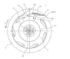
- FIG. 3 is a plan view schematically illustrating the turbo fan illustrated in FIG. 2.
- FIG. 3 is an enlarged side view schematically illustrating the turbo fan shown in FIG. 2.
- FIG. 3 is a perspective view illustrating a blade leading edge and a blade trailing edge of the turbofan illustrated in FIG. 2.
- FIG. 3 is a cross-sectional view of the turbo fan shown in FIG. 2 in plan view (position of a blade leading edge curve point).
- FIG. 3 is a cross-sectional view in plan view of the turbofan shown in FIG.
- FIG. 3 is a cross-sectional view of the turbo fan shown in FIG. 2 in plan view (a shroud-side blade leading edge).
- FIG. 3 is a cross-sectional view of the turbofan shown in FIG. 2 in plan view (a shroud-side front edge end point).
- FIG. 3 is a cross-sectional view of the turbo fan shown in FIG. 2 in a side view (position of a blade leading edge curve point).
- wing trailing edge of the turbo fan shown in FIG. The expanded view which shows the blade
- FIG. 1 is a longitudinal sectional view schematically showing an air conditioner according to Embodiment 1 of the present invention.
- a ceiling-embedded air conditioner 100 is embedded in a recess 19 formed in a ceiling surface 18 of a room 17 and includes an air conditioner body 10 and a turbo housed in the air conditioner body 10.
- the fan 1 and the heat exchanger 16 are included.
- the air conditioner main body 10 is a box formed of a main body side plate 10b that forms a cylindrical body having a rectangular cross section, and a main body top plate 10a that is made of a rectangular plate material that closes one end surface of the cylindrical body.
- the decorative panel 11 is detachably attached to the opening of the box (the surface facing the main body top plate 10a). That is, the main body top plate 10 a is positioned above the ceiling surface 18, and the decorative panel 11 is positioned substantially flush with the ceiling surface 18.
- a suction grill 11a that is a suction port for air to the air conditioner main body 10 is formed, and a filter 12 for removing dust after passing through the suction grill 11a is disposed.
- a panel outlet 11b which is an air outlet, is formed, and the direction of the air blown out to the panel outlet 11b is adjusted.
- a wind direction vane 13 is installed.
- a fan motor 15 is installed at the center of the main body top plate 10 a, and the turbo fan 1 is installed on the rotating shaft of the fan motor 15. Between the suction grill 11a and the turbo fan 1, a bell mouth 14 that forms a suction air passage from the former to the latter is arranged so as to surround the outer peripheral side of the turbo fan 1 (for example, substantially in plan view).
- a heat exchanger 16 is arranged (in a C shape). The heat exchanger 16 has fins arranged substantially horizontally at a predetermined interval, and a heat transfer pipe that penetrates the fin, and the heat transfer pipe is connected to an outdoor unit by a connection pipe (both not shown). Connected, cooled or heated refrigerant is supplied.
- the air in the room 17 is sucked into the suction grill 11 a of the decorative panel 11 when the turbo fan 1 rotates.
- the air removed from the filter 12 is guided by the bell mouth 14 that forms the main body suction port 10 c and is sucked into the turbofan 1.
- the turbo fan 1 the air sucked from the lower side to the upper side is blown out in a substantially horizontal direction.
- the blown air is subjected to heat exchange or humidity adjustment while passing through the heat exchanger 16, and is then blown out from the panel blower outlet 11 b toward the room 17 by changing the flow direction substantially downward.
- the wind direction is controlled by the wind direction vane 13 at the panel outlet 11b.
- the turbo fan 1 is the same as the turbo fan according to the second embodiment of the present invention, which will be described in detail separately, so that the air conditioner 100 with high quality, high performance, and low noise can be obtained. That is, when the turbofan 1 has a pressure loss body that can ventilate the main body inlet 10c side, the panel outlet 11b side, or both, and the pressure loss body provided in the inlet port is, for example, the filter 12, it can be operated for a long time. Even if dust accumulates and ventilation resistance increases, the blade leading edge 4a is curved, so that it is difficult to peel off and low noise can be maintained even during long-time operation.
- positioned at the panel blower outlet 11b is the heat exchanger 16 or a humidification rotor
- release can be performed effectively in the heat exchanger 16 or the humidification rotor whole.
- the distance between the turbofan 1 and the heat exchanger 16 is non-uniform because the heat exchanger 16 is substantially square, noise reduction can be achieved (this will be described in detail separately). ).
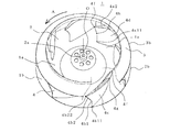
- FIG. 2 is a perspective view
- FIG. 3 is a plan view
- FIG. FIG. 4B is an enlarged side view in section (viewed in the direction of the arrow B shown in FIG. 3)
- FIG. 4B is an enlarged side view partially cut in section (viewed in the direction of the arrow C in FIG. 3)
- FIG. 5B is a perspective view schematically showing the trailing edge of the blade
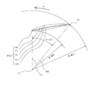
- FIGS. 6 to 10 are sectional views in plan view
- FIGS. FIG. 14 is a side view showing the blade trailing edge
- the turbo fan 1 is described as being mounted on the air conditioner 100 (Embodiment 1), the present invention is not limited to this, and the air blower in various air conditioners and various devices. It is mounted as a means.
- the upper side in the figure is the room 17 side. That is, the turbofan 1 is removed from the ceiling surface 18, the main body top plate 10 a is placed on the floor surface, and the main body suction port 10 c is up, so that air flows from the upper side to the lower side in the figure. To be sucked.
- symbol is attached
- a turbofan 1 includes a main plate 2 that is a rotating body having a flat outer peripheral portion and a central portion protruding in a mountain shape, a substantially annular shroud 3 that faces the main plate 2, and one end portion. Is formed of a plurality of blades 4 joined to the shroud 3 at the other end (same as if formed integrally). 2 and 3, the hatched portion indicates a state when the shroud 3 is peeled off from the blade 4, that is, a joint boundary surface between the shroud 3 and the blade 4.
- a boss 2a is formed at the center of the main plate 2 (the same as the top of the mountain-shaped protrusion), and the boss 2a is fixed to the rotating shaft of the fan motor 15 (see FIG. 1).
- rotation center O (O) the center of the rotation axis.
- the shroud 3 has an upper edge that forms a fan suction port 1a, and the inner diameter increases as it goes downward from the fan suction port 1a (as it approaches the main plate 2).
- the lower edge of the shroud 3 (inner diameter is the largest (hereinafter referred to as “shroud outer periphery”) 3b, and the outer periphery of the main plate 2 (hereinafter referred to as “main plate outer periphery”) 2b opposed thereto,
- the four of the blades 4 and the blade trailing edge 4b farthest from the rotation center O of the pair of blades 4 are located on the same virtual cylindrical surface (hereinafter referred to as “virtual outer peripheral cylinder”), and the fan outlet 1b is formed. (To be precise, since it is formed between a pair of blades 4, when there are seven blades, seven fan outlets 1b are formed on the circumference).
- the blade leading edge 4a of the blade 4 is located at a predetermined distance from the rotation center O
- the blade trailing edge 4b is located on the virtual outer peripheral cylinder, and an imaginary line (hereinafter referred to as “string line”) connecting the blade leading edge 4a and the blade trailing edge 4b is against radiation from the rotation center O.
- string line an imaginary line connecting the blade leading edge 4a and the blade trailing edge 4b is against radiation from the rotation center O.
- rotation direction A indicated by an arrow A in the figure
- counter-rotation direction the direction away from the blade leading edge 4a
- the blade outer surface (corresponding to the positive pressure surface) 4c which is the surface far from the rotation center O of the blade 4, is further away from the rotation center O in the counter-rotating direction, and the blade trailing edge 4b of the blade 4 is the virtual outer periphery.
- a blade inner surface (corresponding to a negative pressure surface) 4d which is a surface closer to the rotation center O of the blade 4, has a similar configuration while taking a predetermined distance (equivalent to the thickness of the blade 4) from the blade outer surface 4c. Presents. At this time, the predetermined interval (equivalent to the thickness of the blade 4) becomes thick in the middle between the blade leading edge 4a and the blade trailing edge 4b, and gradually decreases toward both edge portions.
- a line indicating the center position of the blade outer surface 4c and the blade inner surface 4d in a plane parallel to the main plate 2 is referred to as a “horizontal warp line P”, and an end point of the blade leading edge 4a and an end point of the blade trailing edge 4b
- the connecting straight line is called “horizontal chord line S”.
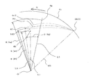
- (Blade leading edge) 4A shows the blade 4 viewed from the rotation center O in the radial direction (same as the direction of the arrow B shown in FIG. 3 and the direction perpendicular to the horizontal chord line S1), and FIG.
- the blade 4 is seen in the direction of the horizontal chord line S1 (the direction of the arrow C shown in FIG. 3).
- the blade leading edge 4a is roughly divided into a main plate side blade leading edge 4a1, a protruding blade leading edge 4a3, and a shroud side blade leading edge 4a2 from the main plate 2 toward the shroud 3.
- the main plate side blade front edge 4a1 includes a main plate side front edge vertical portion 40a1 which is a range perpendicular to the main plate 2, a main plate side front edge skirt portion 41a1 which is a predetermined range close to the main plate 2, and a main plate side front edge vertical. It is divided into a main plate side front edge inclined portion 42a1 which is bent at the portion 40a1 and the leading edge bending point 4h and is connected to the protruding blade leading edge 4a3.
- the large division of the main plate side blade leading edge 4a1 or the like, or the small division of the main plate side leading edge vertical portion 40a1 or the like is for convenience of explanation, and the boundary between them is not clearly shown. However, the range is not limited.
- the blade leading edge 4a gradually retreats from the main plate side front edge end point 4a11, which is a joint portion with the main plate 2, toward the blade trailing edge 4b in the main plate side front edge skirt portion 41a1 (direction in which the width of the blade becomes narrower).
- the main plate side front edge vertical portion 40a1 is perpendicular to the main plate 2 in the range from the end of the main plate side front edge skirt portion 41a1 to the front edge curve point 4h.
- the main plate side leading edge inclined portion 42a1 is bent at the leading edge bending point 4h and is moved forward in the direction opposite to the blade trailing edge 4b (the direction in which the blade width becomes wide), and eventually the protruding blade leading edge 4a3. It is connected to.
- the protruding blade leading edge 4a3 has a substantially arc shape and is connected to the protruding blade leading edge 4a3. Furthermore, the shroud 3 side of the protruding blade leading edge 4a3 is connected to the shroud-side blade leading edge 4a2. The shroud side blade leading edge 4a2 is further away from the main plate 2 as it approaches the blade trailing edge 4b, and is eventually connected to the shroud 3 at the shroud side front edge end point 4g.
- the blade trailing edge 4b is positioned on a virtual cylinder (virtual outer peripheral cylinder) formed by the main plate outer periphery 2b and the shroud outer periphery 3b, and from the main plate 2 toward the shroud 3, the main plate side blade trailing edge 4b1 and the shroud side blade rear Separated from the edge 4b2.
- the main plate side blade trailing edge 4 b 1 is a range perpendicular to the main plate 2.
- the shroud-side blade trailing edge 4b2 bends at the trailing edge curve point 4j, which is substantially the same distance from the main plate 2, and is positioned in a counter-rotating direction (direction in which the width of the blade 4 increases) as it approaches the shroud 3. Soon, it is connected to the shroud 3 at the shroud side rear edge end point 4b22.
- FIG. 6 shows a cross section at the leading edge curved point 4h, that is, a main plate side leading edge vertical portion 40a1 (the same as the range perpendicular to the main plate 2 of the blade leading edge 4a) and a trailing edge curved point 4j (the main plate 2 of the blade trailing edge 4b).
- the same as the range perpendicular to The leading edge bending point 4h is located at a distance R (4h) from the rotation center O.
- the trailing edge bending point 4j is positioned on the virtual outer peripheral cylinder (distance R (4j) from the rotation center O) at a position delayed by an angle ⁇ (4j) in the counter-rotating direction with respect to the leading edge bending point 4h. ing.
- the blade outer surface 4c1 is formed as a convex surface protruding in a direction far from the rotation center O.
- the blade inner surface 4d1 is formed in a convex surface protruding in a direction close to the rotation center O in a range close to the leading edge curved point 4h (same as close to the leading edge 4a), and close to the trailing edge curved point 4j (rear edge) In the same range, which is close to 4b, it is formed as a concave surface that recedes in a direction away from the rotation center O. That is, the radius of curvature when the blade outer surface 4c1 is regarded as an arc (actually not a circular arc) is smaller than the radius of curvature when the blade inner surface 4d1 is regarded as an arc (actually not a circular arc).
- the blade outer surface 4c1 is more greatly warped than the blade inner surface 4d1.
- a line connecting the centers of the blade outer surface 4c1 and the blade inner surface 4d1 is referred to as a “horizontal warp line P1”
- a straight line connecting the leading edge curved point 4h and the trailing edge curved point 4j is referred to as a “horizontal chord line S1”.
- FIG. 7A shows the cross-sectional shape of the joint between the main plate-side blade front edge 4a1 and the main plate 2, that is, the cross-section at the main plate-side front edge end point 4a11 and the main plate-side rear edge end point 4b11.
- FIG. 3 is an enlarged cross-sectional view of a part thereof.
- the main plate side front edge end point 4a11 is in a position (same as “advance”) advanced in the rotation direction A on the outer peripheral side with respect to the front edge curved point 4h.
- the blade outer surface 4c11 is formed as a convex surface protruding in a direction far from the rotation center O.
- the predetermined range close to the main plate side front edge end point 4a11 of the blade outer surface 4c11 deviates (deviations) from the blade inner surface 4d1 (range perpendicular to the main plate 2), and the range away from the main plate side front edge end point 4a11 is It is perpendicular to the main plate 2 and is the same as the blade outer surface 4c1.
- the blade inner surface 4d11 is formed in a convex surface protruding in a direction approaching the rotation center O in a predetermined range close to the main plate side front edge end point 4a11, and a range away from the main plate side front edge end point 4a11 is perpendicular to the main plate 2. However, it is the same as the blade inner surface 4d1.
- the blade outer surface 4c11 and the blade outer surface 4c1, and the blade inner surface 4d11 and the blade inner surface 4d1 are smoothly connected to form the main plate-side front edge skirt 41a1.
- FIG. 8 is a cross-section at the leading edge 4a3 of the protruding blade, and shows a cross-section at the shroud side rear edge end point 4b22.
- the protruding blade leading edge 4a3 is located at a position further in the rotational direction A on the outer peripheral side with respect to the leading edge curved point 4h.
- the protruding front edge end point 4f located on the outermost periphery of the protruding blade front edge 4a3 is a distance R (4f) larger than the distance R (4h) from the rotation center O.
- the shroud side rear edge end point 4b22 is on the virtual outer peripheral cylinder and is delayed by an angle ⁇ (4b22) in the counter-rotating direction. That is, the blade trailing edge 4b bends at the main plate side blade trailing edge 4b1 perpendicular to the main plate 2 and the trailing edge curved point 4j, and recedes in the counter-rotating direction (direction in which the width of the blade 4 increases) as it approaches the shroud 3. It has a shroud side blade trailing edge 4b2.
- the width of the blade 4 at this position is wider than the width of the cross section at the leading edge curved point 4h (same as the leading edge curved point 4h) by an amount equivalent to the angle “ ⁇ (4f) + ⁇ (4b22)”. It will be.
- the blade outer surface 4c3 is formed as a convex surface protruding in a direction far from the rotation center O.
- the blade inner surface 4d3 is formed in a convex surface protruding in a direction close to the rotation center O in the range close to the protruding front edge end point 4f (same as close to the front edge 4a), and close to the shroud side rear edge end point 4b22 (rear) In the same range close to the edge 4b), it is formed as a concave surface that recedes in a direction away from the rotation center O.
- a line connecting the center of the blade outer surface 4c3 and the blade inner surface 4d3 is referred to as a “horizontal warp line P3”, and a straight line connecting the protruding front edge end point 4f and the shroud side rear edge end point 4b22 is referred to as “horizontal chord line S3”.
- FIG. 9 is a cross section at the shroud side blade leading edge 4a2.
- a predetermined position 4i of the shroud side blade leading edge 4a2 is set to a distance R (4i) from the rotation center O, and an angle ⁇ (4i) is set to recede in the counter-rotating direction with respect to the protruding front edge end point 4f. ), The further the position 4i is away from the protruding front edge end point 4f, the more it moves backward in the counter-rotating direction and is positioned on the main plate outer periphery 2b.
- the range of the blade outer surface 4c and the blade inner surface 4d close to the shroud-side blade leading edge 4a2 has a substantially triangular shape bent in a substantially arc shape.
- the lines indicating the blade outer surface 4c and the blade inner surface 4d in the cross section including the position 4i are the blade outer surface 4c2 and the blade inner surface 4d2, and the line connecting the centers of the blade outer surface 4c2 and the blade inner surface 4d2 is “horizontal warp line P2”. Yes.
- the length of the horizontal warp line P2 becomes shorter as the position 4i is away from the main plate 2.
- FIG. 10 is a cross section at the shroud side blade leading edge 4a2.
- the shroud-side front edge end point 4g is retracted (delayed) by an angle ⁇ (4g) in the counter-rotating direction with respect to the protruding front edge end point 4f at a distance R (4g) from the rotation center O. . That is, there is a relationship of “R (4i) ⁇ R (4g), ⁇ (4i) ⁇ (4g)”. In summary, there is the following relationship.
- FIG. 11 is a cross-sectional view for explaining warpage at the blade leading edge 4a, and is a cross section of a plane perpendicular to the main plate 2 passing through the leading edge bending point 4h (more precisely, the main plate 2 and the horizontal chord line S1 (see FIG. 6). ) Is a vertical cross section).
- the perpendicular to the main plate 2 passing through the leading edge curved point 4 h is “perpendicular Q (4 h)”, and for convenience of explanation, the position 4 i happens to be located on the perpendicular Q (4 h).
- the center line (indicated by the alternate long and short dash line in the figure) between the blade outer surface 4c and the blade inner surface 4d is referred to as “vertical warp line Q (4i)”, and the intersection of the vertical warp line Q (4i) with the main plate 2 is referred to as “vertical warp line Q (4i)”.
- the range of the blade outer surface 4c that is equivalent to the main plate side front edge skirt 41a1 is inclined inward (right side in the figure) as the distance from the main plate 2 increases. ⁇ (4a12)> 90 °).
- the inclination angle ⁇ (4a12) formed with the main plate 2 is approximately 90 ° ( ⁇ (4a12) ⁇ 90. °). Therefore, the vertical warp line Q (4i) is inclined inward as the distance from the main plate 2 increases within a range equivalent to the main plate side front edge skirt 41a close to the main plate 2.
- the main plate side front edge vertical portion 40a1 further away from the main plate 2 is perpendicular to the main plate 2 and therefore coincides with the perpendicular Q (4h).
- the vertical warp line Q (4i) is inclined outward as the distance from the main plate 2 is further away from the vertical line Q (4h), and the inclination is gradually increased as the distance from the main plate 2 is increased. It becomes larger and has a substantially constant warpage angle ⁇ (4i) at the leading edge 4a3 of the protruding blade. Accordingly, in the blade 4, near the blade leading edge 4a, the blade outer surface 4c warps more than the blade inner surface 4d (when approximated to an arc, the former radius of curvature is smaller than the latter radius of curvature). .
- FIG. 12 is a cross-sectional view for explaining the warp in the blade middle part, and is a cross section of a plane perpendicular to the main plate 2 passing through the shroud-side front edge end point 4g (more precisely, the main plate 2 and the horizontal chord line S1 (see FIG. 6) ) Is a vertical cross section).
- a position that is in the plane of the main plate 2 and the horizontal chord line S1 passing through the shroud-side front edge point 4g and that is the same distance from the main plate 2 as the front edge curve point 4h is “intermediate curve point 4e”. It is said.
- the intermediate portion of the blade 4 is roughly divided into a main plate-side blade intermediate portion 4e1 close to the main plate 2 and a shroud-side blade intermediate portion 4e2 on the shroud 3 side, with the intermediate bending point 4e as a boundary.
- the main plate side blade intermediate portion 4e1 includes a main plate side intermediate skirt portion 41e1 which is a predetermined range close to the main plate 2, and a main plate side intermediate vertical portion 40e1 which is a range perpendicular to the main plate 2 and which is away from the main plate 2. Divided into small parts.
- the main plate side intermediate skirt portion 41e1, the main plate side intermediate vertical portion 40e1, and the shroud side blade intermediate portion 4e2 are smoothly connected, and the respective boundaries (intermediate bending points 4e) are not limited.
- a line perpendicular to the main plate 2 passing through the intermediate bending point 4e is defined as a perpendicular Q (4e).
- the center line (indicated by the alternate long and short dash line in the figure) between the blade outer surface 4c and the blade inner surface 4d is referred to as “vertical warp line Q (4g)”, and the intersection of the vertical warp line Q (4g) with the main plate 2 is referred to.
- the main plate side intermediate warp point 4a13 is referred to.
- the vertical warp line Q (4g) is inclined inward (right side in the figure) as the distance from the main plate 2 increases.
- the formed inclination angle ⁇ (4a13) is an obtuse angle ( ⁇ (4a13)> 90 °).
- the inclination angle ⁇ (4a13) formed with the main plate 2 is approximately 90 ° ( ⁇ (4a13) ⁇ 90 °. ).
- the vertical warp line Q (4 g) is inclined inward as the distance from the main plate 2 increases in a range close to the main plate 2.
- the main plate side intermediate vertical portion 40e1 further away from the main plate 2 is perpendicular to the main plate 2 and therefore coincides with the perpendicular Q (4e).
- the vertical warp line Q (4g) is inclined outward as the distance from the main plate 2 is further away from the perpendicular Q (4h), and the inclination is gradually increased as the distance from the main plate 2 is increased.
- the warpage angle ⁇ (4 g) is substantially constant.
- the warp angle ⁇ (4i) of the vertical warp line Q (4i) at the blade leading edge 4a (precisely, a position equivalent to the leading edge bending point 4h) is equal to the intermediate bending point 4e (the shroud side leading edge end point 4g).
- the warp angle ⁇ (4 g) of the vertical warp line Q (4 g) at the equivalent position) is larger. That is, the relationship is “( ⁇ (4i)> ⁇ (4g)”. In other words, the blade 4 is gradually approaching the rotation center O (blade leading edge 4a), and the warping angle in a range away from the main plate 2 is gradually increased.
- the flow flowing into the vicinity of the main plate 2 is the main plate 2 and the concave shape.
- concentration of the flow to the main plate 2 side is avoided and the wind speed is made uniform as a whole.
- the radius of curvature of the blade inner surface 4d can be considered to be larger than the radius of curvature of the blade outer surface 4c, so that the angle of attack with the flow flowing into the shroud-side blade leading edge 4a2 is reduced and smooth. Since it flows in, it is prevented from being peeled off and hardly disturbed.
- the warp angle ⁇ (4i) of the vertical warp line Q (4i) increases as it becomes closer to the rotation direction A (closer to the rotation center O) ( ⁇ (4i)> ⁇ (4g )), The shroud side blade leading edge 4a2 and the protruding blade leading edge 4a3 are warped (inclined) toward the rotation direction A side.
- the protruding front edge end point 4f is advanced in the rotational direction A and positioned farther from the rotation center O than the leading edge curved point 4h, and in the side view, the protruding front edge end point 4f is the main plate side front edge. Since the vertical portion 40a1 (same as the leading edge curved point 4h) advances in the rotation direction A, the protruding front edge end point 4f is the apex, the shroud side blade leading edge 4a2 and the protruding blade leading edge 4a3 (main plate side front) A “triangular wing shape” having two sides (including the edge inclined portion 42a1) is formed.
- downstream transition length of the vertical vortex generated in the vicinity of the curved portion of the main plate side front edge inclined portion 42a1 and the shroud side blade front edge 4a2 across the protruding blade leading edge 4a3 (the protruding front edge end point 4f) is too long. Therefore, a stable vortex is generated and the flow is not stably disturbed, so that the noise can be reduced.
- FIG. 13 is a cross-sectional view schematically illustrating the cross-sectional structure of the blade.
- the blade inner surface 4 d is substantially perpendicular to the main plate in a range closer to the main plate 2 than the line connecting the leading edge curved point 4 h and the trailing edge curved point 4 j, while the blade outer surface 4 c is separated from the main plate 2.
- the blade thickness which is the distance between the blade inner surface 4d and the blade outer surface 4c, becomes thinner as the distance from the main plate 2 increases (same as tapering).
- the blade 4 has a hollow structure in which a cavity 4v that opens to the lower surface of the main plate 2 is formed. Therefore, weight reduction can be promoted compared with the case where the blades 4 have a solid structure. Further, since the range close to the main plate 2 of the blades 4 is made of a two-plate structure made of plate-like members having substantially the same thickness as the main plate 2 or the shroud 3, it is easy to integrally mold the turbofan 1 with resin. .
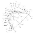
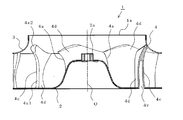
- FIG. 13 and 14 schematically illustrate the trailing edge of the blade
- FIG. 13 is a side view
- FIG. 14 is a developed view in which the outer peripheral virtual cylinder is developed on a plane.
- the blade trailing edge 4b is located on a virtual outer peripheral cylinder (same as a virtual cylinder connecting the main plate outer periphery 2b and the shroud outer periphery 3b).
- the main plate side blade trailing edge 4b1 that is closer to the main plate 2 and less inclined with respect to the main plate 2 and the shroud 3 are located closer to the shroud 3 and closer to the shroud 3 (retracted) in the shroud side. It can be roughly divided into the blade trailing edge 4b2.
- the boundary between the two is not clear, and the position of the boundary is not limited.
- the angle formed by the blade outer surface 4c and the main plate 2 is the inclination angle ⁇ (4b1)
- the angle formed by the blade inner surface 4c and the main plate 2 is the inclination angle ⁇ ( 4b1).
- the main plate-side blade trailing edge 4b1 is the main plate 2 The one closer to is a broad trapezoidal shape.
- the angle formed by the blade outer surface 4c and the shroud 3 is the inclination angle ⁇ (4b2)
- the angle formed by the blade inner surface 4d and the shroud 3 is the inclination angle ⁇ (4b2).
- the shroud side blade trailing edge 4b2 has a substantially rectangular shape.
- the blade outer surface 4c in the range close to the main plate 2 of the main plate side blade trailing edge 4b1 is linearly approximated
- the blade outer surface 4c in the range near the shroud 3 of the shroud side blade trailing edge 4b2 is linearly approximated.
- the intersection point is “outer surface trailing edge curve point 4 kc”
- the blade outer surface 4 c is curved with a curve angle ⁇ (4 kc) around the outer surface trailing edge curve point 4 kc.
- the blade inner surface 4d in the range close to the main plate 2 of the main plate side blade trailing edge 4b1 is linearly approximated
- the blade inner surface 4d in the range close to the shroud 3 of the shroud side blade trailing edge 4b2 is linearly approximated.
- the blade inner surface 4 d is curved with a curve angle ⁇ (4 kd) around the inner surface trailing edge curve point 4 kd.
- the main plate-side blade trailing edge 4b1 has a substantially trapezoidal shape closer to the main plate 2, the blade outer surface 4c is substantially perpendicular to the main plate 2, and the blade inner surface 4d is inclined. A part of the flow toward the main plate 2 side where it is easy to concentrate is directed toward the inner surface trailing edge curved point 4 kd and the shroud 3. As a result, there is no local high-speed flow at the fan outlet 1b, the wind speed distribution becomes uniform, and the flow is stabilized against fluctuations in ventilation resistance. Therefore, the quality stability is improved with low noise and resistance to disturbance.
- the shroud side blade trailing edge 4b2 As the shroud side blade trailing edge 4b2 approaches the shroud 3, the shroud side blade trailing edge 4b2 is positioned in the counter-rotating direction (retreats). That is, in FIG. 8, the rotation center O and the trailing edge curved point 4j (same as the main plate side trailing edge end point 4b11) are formed by the radiation M1 and the radiation M3 connecting the rotation center O and the shroud side trailing edge end point 4b22.
- the angle ⁇ 2 is “5 ° to 10 °”. Therefore, if the angle ⁇ 2 is too small, the flow toward the main plate 2 side of the blade outer surface 4c is concentrated.
- the angle ⁇ 2 is too large, the flow is excessively attracted to the shroud 3 side, the wind speed on the shroud 3 side becomes high, and the wind speed distribution becomes uneven, resulting in noise deterioration. That is, if the angle ⁇ 2 is within the above range (5 ° ⁇ 2 ⁇ 10 °), the wind speed distribution is made uniform, and there is no noticeable high-speed range, so noise can be reduced.
- turbofan according to the present invention can reduce the noise by suppressing the separation and turbulence (vortex generation) of the air flow, it can be widely installed in various devices including a variety of air conditioners and air blowing means. Can do.
- SYMBOLS 1 Turbo fan (Embodiment 2), 1a: Fan suction inlet, 1b: Fan blower outlet, 2: Main plate, 2a: Boss, 2b: Main plate outer periphery, 3: Shroud, 3b: Shroud outer periphery, 4: Blade, 4a : Blade front edge, 4a1: main plate side blade front edge, 4a11: main plate side front edge end point, 4a12: main plate side front edge warp point, 4a13: main plate side intermediate warp point, 4a2: shroud side blade front edge, 4a3: protruding blade Front edge, 4b: Blade trailing edge, 4b1: Main plate side blade trailing edge, 4b11: Main plate side trailing edge end point, 4b2: Shroud side blade trailing edge, 4b22: Shroud side trailing edge end point, 4c: Blade outer surface, 4c1: Blade outer surface 4c11: blade outer surface, 4c2: blade outer surface, 4c2: blade outer
Landscapes
- Engineering & Computer Science (AREA)
- Mechanical Engineering (AREA)
- General Engineering & Computer Science (AREA)
- Physics & Mathematics (AREA)
- Geometry (AREA)
- Structures Of Non-Positive Displacement Pumps (AREA)
Abstract
Priority Applications (6)
| Application Number | Priority Date | Filing Date | Title |
|---|---|---|---|
| US13/319,804 US8834121B2 (en) | 2009-06-11 | 2010-03-16 | Turbo fan and air conditioning apparatus |
| EP10785873.0A EP2441963B1 (fr) | 2009-06-11 | 2010-03-16 | Turboventilateur et climatiseur |
| ES10785873.0T ES2647955T3 (es) | 2009-06-11 | 2010-03-16 | Turboventilador y aparato de aire acondicionado |
| CN201080025499.1A CN102459917B (zh) | 2009-06-11 | 2010-03-16 | 涡轮风扇及空调机 |
| EP17181936.0A EP3273067B1 (fr) | 2009-06-11 | 2010-03-16 | Turboréacteur et conditionneur d'air |
| US14/454,201 US9651056B2 (en) | 2009-06-11 | 2014-08-07 | Turbo fan and air conditioning apparatus |
Applications Claiming Priority (2)
| Application Number | Priority Date | Filing Date | Title |
|---|---|---|---|
| JP2009139986A JP5164932B2 (ja) | 2009-06-11 | 2009-06-11 | ターボファンおよび空気調和機 |
| JP2009-139986 | 2009-06-11 |
Related Child Applications (2)
| Application Number | Title | Priority Date | Filing Date |
|---|---|---|---|
| US13/319,804 A-371-Of-International US8834121B2 (en) | 2009-06-11 | 2010-03-16 | Turbo fan and air conditioning apparatus |
| US14/454,201 Division US9651056B2 (en) | 2009-06-11 | 2014-08-07 | Turbo fan and air conditioning apparatus |
Publications (1)
| Publication Number | Publication Date |
|---|---|
| WO2010143341A1 true WO2010143341A1 (fr) | 2010-12-16 |
Family
ID=43308604
Family Applications (1)
| Application Number | Title | Priority Date | Filing Date |
|---|---|---|---|
| PCT/JP2010/001874 Ceased WO2010143341A1 (fr) | 2009-06-11 | 2010-03-16 | Turboventilateur et climatiseur |
Country Status (6)
| Country | Link |
|---|---|
| US (2) | US8834121B2 (fr) |
| EP (2) | EP2441963B1 (fr) |
| JP (1) | JP5164932B2 (fr) |
| CN (2) | CN102459917B (fr) |
| ES (2) | ES2647955T3 (fr) |
| WO (1) | WO2010143341A1 (fr) |
Cited By (2)
| Publication number | Priority date | Publication date | Assignee | Title |
|---|---|---|---|---|
| EP2426362A3 (fr) * | 2010-09-02 | 2012-10-17 | LG Electronics, Inc. | Turbosoufflante et climatiseur avec turbosoufflante |
| CN113074127A (zh) * | 2020-01-06 | 2021-07-06 | 广东威灵电机制造有限公司 | 送风装置及吸尘器 |
Families Citing this family (38)
| Publication number | Priority date | Publication date | Assignee | Title |
|---|---|---|---|---|
| JP5164932B2 (ja) * | 2009-06-11 | 2013-03-21 | 三菱電機株式会社 | ターボファンおよび空気調和機 |
| JP5730649B2 (ja) * | 2011-04-13 | 2015-06-10 | 株式会社日立製作所 | 羽根車及びそれを有するターボ機械 |
| CN103511335B (zh) * | 2012-06-25 | 2016-08-24 | 珠海格力电器股份有限公司 | 空调、离心风机及其叶片 |
| WO2014061094A1 (fr) | 2012-10-16 | 2014-04-24 | 三菱電機株式会社 | Réacteur à double flux et appareil de conditionnement d'air |
| JP5522306B1 (ja) * | 2012-12-21 | 2014-06-18 | ダイキン工業株式会社 | 遠心ファン |
| KR102076684B1 (ko) * | 2013-02-21 | 2020-02-12 | 엘지전자 주식회사 | 터보팬 및 이를 사용한 천정형 공기조화기 |
| CN103195751B (zh) * | 2013-04-03 | 2015-11-04 | 宁波朗迪叶轮机械有限公司 | 后倾式离心风叶 |
| EP2985542A4 (fr) * | 2013-04-30 | 2017-04-05 | Daikin Industries, Ltd. | Panneau décoratif et unité intérieure de climatiseur comprenant celui-ci |
| JP5783214B2 (ja) * | 2013-09-30 | 2015-09-24 | ダイキン工業株式会社 | 遠心送風機及びこれを備えた空気調和機 |
| CN104564805B (zh) * | 2013-10-29 | 2017-11-10 | 海尔集团公司 | 一种离心风机的扇叶结构、离心风机及嵌入式空调内机 |
| KR102203935B1 (ko) | 2014-01-08 | 2021-01-18 | 삼성전자주식회사 | 토출구 개폐장치 및 이를 포함하는 공기조화기 |
| CN104895835B (zh) * | 2014-03-05 | 2017-11-28 | 海尔集团公司 | 一种离心风扇、离心风扇的制造方法及具有该离心风扇的空调 |
| JP2016084751A (ja) * | 2014-10-27 | 2016-05-19 | 三菱重工業株式会社 | インペラ、遠心式流体機械、及び流体装置 |
| DE102015101938A1 (de) * | 2015-02-11 | 2016-08-11 | Ebm-Papst Mulfingen Gmbh & Co. Kg | Ventilatorrad und Ventilator |
| US10641280B2 (en) * | 2015-05-22 | 2020-05-05 | Samsung Electronics Co., Ltd. | Turbo fan and air conditioner including same |
| CN106337833A (zh) * | 2015-07-06 | 2017-01-18 | 杭州三花研究院有限公司 | 叶轮、离心泵以及电驱动泵 |
| ITUB20152807A1 (it) * | 2015-08-03 | 2017-02-03 | Ma Ti Ka S R L | Ventola per forni per la cottura di alimenti |
| KR102403728B1 (ko) * | 2015-10-07 | 2022-06-02 | 삼성전자주식회사 | 공기조화장치용 터보팬 |
| WO2017106530A1 (fr) * | 2015-12-16 | 2017-06-22 | Daniel Khalitov | Dispositif et procédé d'éjection d'air |
| JP6593539B2 (ja) * | 2016-07-27 | 2019-10-23 | 株式会社デンソー | 遠心送風機 |
| CN106640748B (zh) * | 2017-01-06 | 2022-12-02 | 珠海格力电器股份有限公司 | 叶片、叶轮及风机 |
| JP2018150910A (ja) * | 2017-03-14 | 2018-09-27 | ダイキン工業株式会社 | 両吸込型遠心ファン |
| DE102018204978A1 (de) * | 2018-04-03 | 2019-10-10 | Siemens Healthcare Gmbh | Kühlsystem für eine Bildgebungsvorrichtung mit einer Gantry |
| JP7207933B2 (ja) * | 2018-10-15 | 2023-01-18 | 日立建機株式会社 | 建設機械 |
| EP3647603A1 (fr) | 2018-10-31 | 2020-05-06 | Carrier Corporation | Agencement de roue centrifuge d'un ventilateur pour réduire le bruit |
| CN109899318B (zh) * | 2019-02-22 | 2021-03-30 | 宁波德业日用电器科技有限公司 | 新健康空气净化器的旋涡风扇 |
| CN110566500B (zh) * | 2019-10-12 | 2024-08-16 | 浙江科贸智能机电股份有限公司 | 一种离心通风机的叶轮 |
| JP2021134678A (ja) * | 2020-02-25 | 2021-09-13 | 三菱重工業株式会社 | 遠心圧縮機 |
| DE102020114389A1 (de) * | 2020-05-28 | 2021-12-02 | Ebm-Papst Mulfingen Gmbh & Co. Kg | Gebläserad mit ener nahtlosen Anbindung der Laufradschaufeln an einen Scheibenkörper |
| DE102020114387A1 (de) * | 2020-05-28 | 2021-12-02 | Ebm-Papst Mulfingen Gmbh & Co. Kg | Gebläserad mit dreidimensional gekrümmten Laufradschaufeln |
| US11686315B2 (en) * | 2020-08-11 | 2023-06-27 | Hunter Fan Company | Ceiling fan and impeller blade |
| WO2022055112A1 (fr) * | 2020-09-09 | 2022-03-17 | 삼성전자주식회사 | Ventilateur, climatiseur présentant un ventilateur et procédé de fabrication de ventilateur |
| CN116507808B (zh) * | 2020-11-25 | 2025-04-22 | 三菱电机株式会社 | 涡轮风扇以及空调机 |
| CN112392547A (zh) * | 2020-11-30 | 2021-02-23 | 中国航发动力股份有限公司 | 一种旋转机械的转子连接结构 |
| US20240209755A1 (en) * | 2021-06-03 | 2024-06-27 | Howard Purdum | Reaction turbine operating on condensing vapors |
| JP7697401B2 (ja) * | 2022-04-21 | 2025-06-24 | 株式会社デンソー | 送風機 |
| CN116592460B (zh) * | 2023-04-19 | 2026-01-23 | 安徽奥克斯智能电气有限公司 | 摆风控制方法、装置、空调器及存储介质 |
| US12510097B1 (en) | 2024-08-14 | 2025-12-30 | Regal Beloit America, Inc. | Axial fan and housing assembly and methods of use thereof |
Citations (6)
| Publication number | Priority date | Publication date | Assignee | Title |
|---|---|---|---|---|
| JPH05312191A (ja) * | 1992-03-11 | 1993-11-22 | Daikin Ind Ltd | 遠心ファン |
| JP3092554B2 (ja) | 1997-09-30 | 2000-09-25 | ダイキン工業株式会社 | 遠心送風機及びその製造方法並びに該遠心送風機を備えた空気調和機 |
| JP2006002689A (ja) * | 2004-06-18 | 2006-01-05 | Hitachi Home & Life Solutions Inc | 送風機 |
| JP3861008B2 (ja) | 2002-01-10 | 2006-12-20 | 三菱重工業株式会社 | ターボファン及びそれを備えた空気調和装置 |
| JP2007205269A (ja) | 2006-02-02 | 2007-08-16 | Daikin Ind Ltd | 遠心ファン |
| JP2008002379A (ja) * | 2006-06-23 | 2008-01-10 | Daikin Ind Ltd | 遠心ファン |
Family Cites Families (12)
| Publication number | Priority date | Publication date | Assignee | Title |
|---|---|---|---|---|
| CH512703A (it) * | 1969-08-07 | 1971-09-15 | Riello Condizionatori S A S | Apparecchio condizionatore, per il condizionamento ambientale di locali |
| US4231706A (en) * | 1977-04-27 | 1980-11-04 | Hitachi, Ltd. | Impeller of a centrifugal blower |
| JP2730396B2 (ja) | 1992-05-13 | 1998-03-25 | ダイキン工業株式会社 | 遠心ファンの羽根車 |
| JP2730395B2 (ja) | 1992-05-13 | 1998-03-25 | ダイキン工業株式会社 | 空気調和装置 |
| DE4311746A1 (de) * | 1993-04-08 | 1994-10-13 | Klein Schanzlin & Becker Ag | Kreiselpumpenlaufrad |
| US5478201A (en) * | 1994-06-13 | 1995-12-26 | Carrier Corporation | Centrifugal fan inlet orifice and impeller assembly |
| US6338610B1 (en) * | 1998-01-14 | 2002-01-15 | Ebara Corporation | Centrifugal turbomachinery |
| US6042335A (en) * | 1998-05-04 | 2000-03-28 | Carrier Corporation | Centrifugal flow fan and fan/orifice assembly |
| JP2001159396A (ja) * | 1999-12-03 | 2001-06-12 | Daikin Ind Ltd | 遠心ファン及び該遠心ファンを備えた空気調和機 |
| KR100405981B1 (ko) * | 2001-02-12 | 2003-11-14 | 엘지전자 주식회사 | 천정형 공조기의 터보팬 구조 |
| JP2003090298A (ja) * | 2001-09-17 | 2003-03-28 | Nippon Soken Inc | 遠心ファン |
| JP5164932B2 (ja) * | 2009-06-11 | 2013-03-21 | 三菱電機株式会社 | ターボファンおよび空気調和機 |
-
2009
- 2009-06-11 JP JP2009139986A patent/JP5164932B2/ja not_active Expired - Fee Related
-
2010
- 2010-03-16 WO PCT/JP2010/001874 patent/WO2010143341A1/fr not_active Ceased
- 2010-03-16 CN CN201080025499.1A patent/CN102459917B/zh not_active Expired - Fee Related
- 2010-03-16 ES ES10785873.0T patent/ES2647955T3/es active Active
- 2010-03-16 EP EP10785873.0A patent/EP2441963B1/fr not_active Not-in-force
- 2010-03-16 EP EP17181936.0A patent/EP3273067B1/fr not_active Not-in-force
- 2010-03-16 CN CN201510144533.1A patent/CN104791298A/zh active Pending
- 2010-03-16 ES ES17181936T patent/ES2794580T3/es active Active
- 2010-03-16 US US13/319,804 patent/US8834121B2/en active Active
-
2014
- 2014-08-07 US US14/454,201 patent/US9651056B2/en not_active Expired - Fee Related
Patent Citations (6)
| Publication number | Priority date | Publication date | Assignee | Title |
|---|---|---|---|---|
| JPH05312191A (ja) * | 1992-03-11 | 1993-11-22 | Daikin Ind Ltd | 遠心ファン |
| JP3092554B2 (ja) | 1997-09-30 | 2000-09-25 | ダイキン工業株式会社 | 遠心送風機及びその製造方法並びに該遠心送風機を備えた空気調和機 |
| JP3861008B2 (ja) | 2002-01-10 | 2006-12-20 | 三菱重工業株式会社 | ターボファン及びそれを備えた空気調和装置 |
| JP2006002689A (ja) * | 2004-06-18 | 2006-01-05 | Hitachi Home & Life Solutions Inc | 送風機 |
| JP2007205269A (ja) | 2006-02-02 | 2007-08-16 | Daikin Ind Ltd | 遠心ファン |
| JP2008002379A (ja) * | 2006-06-23 | 2008-01-10 | Daikin Ind Ltd | 遠心ファン |
Cited By (3)
| Publication number | Priority date | Publication date | Assignee | Title |
|---|---|---|---|---|
| EP2426362A3 (fr) * | 2010-09-02 | 2012-10-17 | LG Electronics, Inc. | Turbosoufflante et climatiseur avec turbosoufflante |
| US8668460B2 (en) | 2010-09-02 | 2014-03-11 | Lg Electronics Inc. | Turbo fan and air conditioner with turbo fan |
| CN113074127A (zh) * | 2020-01-06 | 2021-07-06 | 广东威灵电机制造有限公司 | 送风装置及吸尘器 |
Also Published As
| Publication number | Publication date |
|---|---|
| US20150030454A1 (en) | 2015-01-29 |
| EP3273067B1 (fr) | 2020-04-22 |
| CN102459917A (zh) | 2012-05-16 |
| EP2441963A1 (fr) | 2012-04-18 |
| JP2010285925A (ja) | 2010-12-24 |
| US8834121B2 (en) | 2014-09-16 |
| US9651056B2 (en) | 2017-05-16 |
| EP3273067A1 (fr) | 2018-01-24 |
| US20120063899A1 (en) | 2012-03-15 |
| JP5164932B2 (ja) | 2013-03-21 |
| ES2794580T3 (es) | 2020-11-18 |
| CN102459917B (zh) | 2015-04-29 |
| ES2647955T3 (es) | 2017-12-27 |
| EP2441963A4 (fr) | 2015-09-09 |
| EP2441963B1 (fr) | 2017-10-18 |
| CN104791298A (zh) | 2015-07-22 |
Similar Documents
| Publication | Publication Date | Title |
|---|---|---|
| JP5164932B2 (ja) | ターボファンおよび空気調和機 | |
| JP5955402B2 (ja) | ターボファンおよび空気調和機 | |
| CN102422025B (zh) | 离心风扇及空调机 | |
| JP4396775B2 (ja) | 遠心ファン | |
| EP2264320B1 (fr) | Turboventilateur et climatiseur | |
| JP5425270B2 (ja) | ターボファンおよび空気調和機 | |
| JP6215296B2 (ja) | プロペラファン及びこれを備えた空気調和機 | |
| JP5111582B2 (ja) | 遠心ファンとこれを備えた空気調和装置及び遠心ファンの金型 | |
| JP5127854B2 (ja) | 送風機及びヒートポンプ装置 | |
| JP2008232049A (ja) | 遠心羽根車と遠心送風機 | |
| JPWO2020161850A1 (ja) | 遠心送風機及びそれを用いた空気調和機 | |
| JP2001159396A (ja) | 遠心ファン及び該遠心ファンを備えた空気調和機 | |
| WO2015063850A1 (fr) | Ventilateur tangentiel et climatiseur | |
| JP6625213B2 (ja) | 多翼ファン及び空気調和機 | |
| WO2023188420A1 (fr) | Turbine à flux axial et soufflante à flux axial |
Legal Events
| Date | Code | Title | Description |
|---|---|---|---|
| WWE | Wipo information: entry into national phase |
Ref document number: 201080025499.1 Country of ref document: CN |
|
| 121 | Ep: the epo has been informed by wipo that ep was designated in this application |
Ref document number: 10785873 Country of ref document: EP Kind code of ref document: A1 |
|
| WWE | Wipo information: entry into national phase |
Ref document number: 13319804 Country of ref document: US |
|
| REEP | Request for entry into the european phase |
Ref document number: 2010785873 Country of ref document: EP |
|
| WWE | Wipo information: entry into national phase |
Ref document number: 2010785873 Country of ref document: EP |
|
| NENP | Non-entry into the national phase |
Ref country code: DE |