WO2010143341A1 - ターボファンおよび空気調和機 - Google Patents
ターボファンおよび空気調和機 Download PDFInfo
- Publication number
- WO2010143341A1 WO2010143341A1 PCT/JP2010/001874 JP2010001874W WO2010143341A1 WO 2010143341 A1 WO2010143341 A1 WO 2010143341A1 JP 2010001874 W JP2010001874 W JP 2010001874W WO 2010143341 A1 WO2010143341 A1 WO 2010143341A1
- Authority
- WO
- WIPO (PCT)
- Prior art keywords
- blade
- main plate
- edge
- shroud
- leading edge
- Prior art date
- Legal status (The legal status is an assumption and is not a legal conclusion. Google has not performed a legal analysis and makes no representation as to the accuracy of the status listed.)
- Ceased
Links
Images








Classifications
-
- F—MECHANICAL ENGINEERING; LIGHTING; HEATING; WEAPONS; BLASTING
- F04—POSITIVE - DISPLACEMENT MACHINES FOR LIQUIDS; PUMPS FOR LIQUIDS OR ELASTIC FLUIDS
- F04D—NON-POSITIVE-DISPLACEMENT PUMPS
- F04D29/00—Details, component parts, or accessories
- F04D29/26—Rotors specially for elastic fluids
- F04D29/28—Rotors specially for elastic fluids for centrifugal or helico-centrifugal pumps for radial-flow or helico-centrifugal pumps
- F04D29/281—Rotors specially for elastic fluids for centrifugal or helico-centrifugal pumps for radial-flow or helico-centrifugal pumps for fans or blowers
-
- F—MECHANICAL ENGINEERING; LIGHTING; HEATING; WEAPONS; BLASTING
- F04—POSITIVE - DISPLACEMENT MACHINES FOR LIQUIDS; PUMPS FOR LIQUIDS OR ELASTIC FLUIDS
- F04D—NON-POSITIVE-DISPLACEMENT PUMPS
- F04D25/00—Pumping installations or systems
- F04D25/02—Units comprising pumps and their driving means
- F04D25/08—Units comprising pumps and their driving means the working fluid being air, e.g. for ventilation
- F04D25/088—Ceiling fans
-
- F—MECHANICAL ENGINEERING; LIGHTING; HEATING; WEAPONS; BLASTING
- F04—POSITIVE - DISPLACEMENT MACHINES FOR LIQUIDS; PUMPS FOR LIQUIDS OR ELASTIC FLUIDS
- F04D—NON-POSITIVE-DISPLACEMENT PUMPS
- F04D29/00—Details, component parts, or accessories
- F04D29/18—Rotors
- F04D29/22—Rotors specially for centrifugal pumps
- F04D29/24—Vanes
- F04D29/242—Geometry, shape
-
- F—MECHANICAL ENGINEERING; LIGHTING; HEATING; WEAPONS; BLASTING
- F04—POSITIVE - DISPLACEMENT MACHINES FOR LIQUIDS; PUMPS FOR LIQUIDS OR ELASTIC FLUIDS
- F04D—NON-POSITIVE-DISPLACEMENT PUMPS
- F04D29/00—Details, component parts, or accessories
- F04D29/18—Rotors
- F04D29/22—Rotors specially for centrifugal pumps
- F04D29/24—Vanes
- F04D29/242—Geometry, shape
- F04D29/245—Geometry, shape for special effects
-
- F—MECHANICAL ENGINEERING; LIGHTING; HEATING; WEAPONS; BLASTING
- F04—POSITIVE - DISPLACEMENT MACHINES FOR LIQUIDS; PUMPS FOR LIQUIDS OR ELASTIC FLUIDS
- F04D—NON-POSITIVE-DISPLACEMENT PUMPS
- F04D29/00—Details, component parts, or accessories
- F04D29/26—Rotors specially for elastic fluids
- F04D29/28—Rotors specially for elastic fluids for centrifugal or helico-centrifugal pumps for radial-flow or helico-centrifugal pumps
- F04D29/281—Rotors specially for elastic fluids for centrifugal or helico-centrifugal pumps for radial-flow or helico-centrifugal pumps for fans or blowers
- F04D29/282—Rotors specially for elastic fluids for centrifugal or helico-centrifugal pumps for radial-flow or helico-centrifugal pumps for fans or blowers the leading edge of each vane being substantially parallel to the rotation axis
-
- F—MECHANICAL ENGINEERING; LIGHTING; HEATING; WEAPONS; BLASTING
- F04—POSITIVE - DISPLACEMENT MACHINES FOR LIQUIDS; PUMPS FOR LIQUIDS OR ELASTIC FLUIDS
- F04D—NON-POSITIVE-DISPLACEMENT PUMPS
- F04D29/00—Details, component parts, or accessories
- F04D29/26—Rotors specially for elastic fluids
- F04D29/28—Rotors specially for elastic fluids for centrifugal or helico-centrifugal pumps for radial-flow or helico-centrifugal pumps
- F04D29/30—Vanes
-
- F—MECHANICAL ENGINEERING; LIGHTING; HEATING; WEAPONS; BLASTING
- F04—POSITIVE - DISPLACEMENT MACHINES FOR LIQUIDS; PUMPS FOR LIQUIDS OR ELASTIC FLUIDS
- F04D—NON-POSITIVE-DISPLACEMENT PUMPS
- F04D29/00—Details, component parts, or accessories
- F04D29/66—Combating cavitation, whirls, noise, vibration or the like; Balancing
- F04D29/661—Combating cavitation, whirls, noise, vibration or the like; Balancing especially adapted for elastic fluid pumps
- F04D29/667—Combating cavitation, whirls, noise, vibration or the like; Balancing especially adapted for elastic fluid pumps by influencing the flow pattern, e.g. suppression of turbulence
-
- F—MECHANICAL ENGINEERING; LIGHTING; HEATING; WEAPONS; BLASTING
- F05—INDEXING SCHEMES RELATING TO ENGINES OR PUMPS IN VARIOUS SUBCLASSES OF CLASSES F01-F04
- F05D—INDEXING SCHEME FOR ASPECTS RELATING TO NON-POSITIVE-DISPLACEMENT MACHINES OR ENGINES, GAS-TURBINES OR JET-PROPULSION PLANTS
- F05D2240/00—Components
- F05D2240/20—Rotors
- F05D2240/30—Characteristics of rotor blades, i.e. of any element transforming dynamic fluid energy to or from rotational energy and being attached to a rotor
- F05D2240/303—Characteristics of rotor blades, i.e. of any element transforming dynamic fluid energy to or from rotational energy and being attached to a rotor related to the leading edge of a rotor blade
-
- F—MECHANICAL ENGINEERING; LIGHTING; HEATING; WEAPONS; BLASTING
- F05—INDEXING SCHEMES RELATING TO ENGINES OR PUMPS IN VARIOUS SUBCLASSES OF CLASSES F01-F04
- F05D—INDEXING SCHEME FOR ASPECTS RELATING TO NON-POSITIVE-DISPLACEMENT MACHINES OR ENGINES, GAS-TURBINES OR JET-PROPULSION PLANTS
- F05D2240/00—Components
- F05D2240/20—Rotors
- F05D2240/30—Characteristics of rotor blades, i.e. of any element transforming dynamic fluid energy to or from rotational energy and being attached to a rotor
- F05D2240/304—Characteristics of rotor blades, i.e. of any element transforming dynamic fluid energy to or from rotational energy and being attached to a rotor related to the trailing edge of a rotor blade
Definitions
- the present invention relates to a turbo fan and an air conditioner, and more particularly to a turbo fan used in an air conditioner that performs air cleaning, humidification / dehumidification, air conditioning, and the like, and an air conditioner using the turbo fan.
- a turbo fan in which fan blades are formed in a three-dimensional shape has been widely used.
- the blade crosses from the leading edge to the trailing edge, and the position of the joining edge on the side plate side shifts in the rotation direction A with respect to the joining edge with the main plate (the imaginary line connecting the leading edge and the trailing edge is inclined with respect to the radiation)
- the shroud end portion on the front edge side of the blade is inclined toward the rotation direction A (see, for example, Patent Document 1).
- the shroud side end portion on the blade leading edge side where the axial velocity component of the inflowing air is particularly large is inclined toward the rotation direction A side in the inflow direction of the inflowing air. Therefore, peeling that tends to occur in the counter-rotation direction side can be prevented, and performance improvement and noise reduction can be achieved.
- a first tangent line in contact with the trailing edge at the connecting position (first connecting position) between the main plate and the blade at the trailing edge of the blade extends toward the blade rotation direction A so as to approach the shroud, and the side plate.
- a second tangent line that contacts the trailing edge extends so as to approach the main plate toward the rotation direction A side of the blade (for example, Patent Document 2). reference).
- a turbofan that has a sawtooth shape at the blade trailing edge is disclosed (for example, see Patent Document 3).
- a turbo fan By forming a turbo fan in this way, the pressure gradient and velocity deficit of the air flow associated with the flow merge at the rear edge is reduced compared to those with a straight rear edge, and turbulence is suppressed and noise is reduced. Can be achieved.
- Japanese Patent No. 3861008 pages 7-8, FIG. 5) JP 2007-205269 A (page 5-6, FIG. 7) Japanese Patent No. 3092554 (page 4-5, FIG. 1)
- the conventional turbo fan and the air conditioner using the turbo fan have the following problems.
- the thickness of the blade at an arbitrary same radius around the rotation center O is almost the same in the height direction of the impeller, so a thermoplastic resin such as ABS or Ps is used as a material.
- a thermoplastic resin such as ABS or Ps is used as a material.
- the blades are solid and the weight may increase.
- the first tangent line in contact with the rear edge is on the blade rotation direction A side at the connection position (first connection position) between the main plate and the blade at the trailing edge of the blade. Extending so as to approach the shroud, and at the connecting position (second connecting position) between the side plate and the blade, the second tangent line contacting the rear edge approaches the main plate toward the rotation direction A side of the blade. Elongated, the rear edge of the uniform thickness is formed in a substantially square shape in side view. For this reason, the flow is concentrated on the main plate side and the side plate side in the rotation direction A surface of the blade, and the vicinity of the center is difficult to flow.
- the half-rotation direction A surface of the blade is substantially the same shape as the rotation direction A surface, the distance between the blades of adjacent blades is the same in the height direction of the impeller, and in the rotation direction A surface.
- the flow is concentrated on the main plate side and the side plate side. For this reason, the flow becomes unstable near the center in the height direction and may be separated, resulting in noise deterioration.
- a thermoplastic resin such as ABS or Ps is used as a material. In the case of molding into wings, the blades are solid and the weight may increase.
- the present invention has been made to solve the above problems, and has an object to obtain a turbo fan capable of suppressing separation and turbulence (vortex generation) of an air flow, and an air conditioner equipped with the turbo fan. To do.
- a turbofan according to the present invention includes a disc-shaped main plate having a center of rotation and a protruding boss formed near the center of rotation, A cylindrical shroud that is disposed opposite to the main plate and has a diameter-expanded portion that increases in inner diameter as it approaches the main plate; A turbofan having a plurality of blades bonded at both ends to the main plate and the shroud, The blade trailing edge of the blade is located on a virtual cylinder formed by the outer periphery of the disk and the outer periphery of the shroud, and the blade leading edge of the blade is closer to the rotation center than the blade trailing edge of the blade.
- the blade outer surface which is a surface far from the rotation center of the blade, is formed as a convex surface protruding in a direction away from the rotation center
- the blade leading edge includes a main plate side blade leading edge close to the main plate, a shroud side blade leading edge close to the shroud, and a protruding blade formed between the main plate side blade leading edge and the shroud blade leading edge. Divided into a leading edge, The main plate side blade leading edge closer to the main plate forms a main plate side leading edge skirt that is inclined away from the rotation center while being away from the blade trailing edge as the main plate is closer to the main plate side.
- the range farther from the main plate than the front edge skirt portion forms a main plate side front edge vertical portion perpendicular to the main plate,
- the main plate-side leading edge vertical portion is more distant from the main plate than the main plate-side front edge vertical portion, and the main plate is inclined so as to move away from the rotation center while being further away from the blade trailing edge as the distance from the main plate is further away from the main plate.
- the main plate side front edge skirt portion that gradually leans toward the rotation center while gradually approaching the blade trailing edge.
- a main plate side front edge vertical portion, a main plate side front edge vertical portion, a main plate side front edge vertical portion, and a main plate side front edge inclined portion which is inclined away from the blade center while gradually moving away from the blade rear edge, and the main plate side front edge inclined portion.
- leading blade leading edge that protrudes in the direction farthest from the blade trailing edge and away from the rotation center
- shroud blade leading edge that is connected to the protruding blade leading edge and tilts away from the rotation center while approaching the blade trailing edge And an edge.
- the blade leading edge is curved in the direction away from the center of rotation, in the forward direction in which the position close to the main plate and the range including the protruding blade leading edge both advance in the rotational direction.
- attraction of the suction flow is promoted.
- the main plate side front edge skirt portion the angle formed with the main plate is an obtuse angle
- the flow flowing into the vicinity of the main plate is near the center of the curve (the main plate side front edge vertical portion and the main plate side front edge inclined portion and Therefore, the concentration of the flow toward the main plate can be avoided. Therefore, it is possible to make the wind speed uniform throughout.
- the protruding front edge end point advances in the rotational direction from the main plate side front edge vertical portion (same as the front edge curved point), and therefore, the protruding front edge end point is the apex, and the shroud blade front edge Since a "triangular wing shape" with two sides of the leading edge of the protruding blade (including the main plate side leading edge slope) is formed, a vertical vortex from the blade outer surface toward the inner surface is generated, In addition to attracting the flow, even if the draft resistance changes on the suction side, the flow is supplied to the blade surface by the vertical vortex, so that it does not peel off. As described above, the turbofan according to the present invention can reduce the noise since the passage air speed between the blades can be made uniform and separation on the blade surface can be prevented.
- FIG. 3 is a plan view schematically illustrating the turbo fan illustrated in FIG. 2.
- FIG. 3 is an enlarged side view schematically illustrating the turbo fan shown in FIG. 2.
- FIG. 3 is a perspective view illustrating a blade leading edge and a blade trailing edge of the turbofan illustrated in FIG. 2.
- FIG. 3 is a cross-sectional view of the turbo fan shown in FIG. 2 in plan view (position of a blade leading edge curve point).
- FIG. 3 is a cross-sectional view in plan view of the turbofan shown in FIG.
- FIG. 3 is a cross-sectional view of the turbo fan shown in FIG. 2 in plan view (a shroud-side blade leading edge).
- FIG. 3 is a cross-sectional view of the turbofan shown in FIG. 2 in plan view (a shroud-side front edge end point).
- FIG. 3 is a cross-sectional view of the turbo fan shown in FIG. 2 in a side view (position of a blade leading edge curve point).
- wing trailing edge of the turbo fan shown in FIG. The expanded view which shows the blade
- FIG. 1 is a longitudinal sectional view schematically showing an air conditioner according to Embodiment 1 of the present invention.
- a ceiling-embedded air conditioner 100 is embedded in a recess 19 formed in a ceiling surface 18 of a room 17 and includes an air conditioner body 10 and a turbo housed in the air conditioner body 10.
- the fan 1 and the heat exchanger 16 are included.
- the air conditioner main body 10 is a box formed of a main body side plate 10b that forms a cylindrical body having a rectangular cross section, and a main body top plate 10a that is made of a rectangular plate material that closes one end surface of the cylindrical body.
- the decorative panel 11 is detachably attached to the opening of the box (the surface facing the main body top plate 10a). That is, the main body top plate 10 a is positioned above the ceiling surface 18, and the decorative panel 11 is positioned substantially flush with the ceiling surface 18.
- a suction grill 11a that is a suction port for air to the air conditioner main body 10 is formed, and a filter 12 for removing dust after passing through the suction grill 11a is disposed.
- a panel outlet 11b which is an air outlet, is formed, and the direction of the air blown out to the panel outlet 11b is adjusted.
- a wind direction vane 13 is installed.
- a fan motor 15 is installed at the center of the main body top plate 10 a, and the turbo fan 1 is installed on the rotating shaft of the fan motor 15. Between the suction grill 11a and the turbo fan 1, a bell mouth 14 that forms a suction air passage from the former to the latter is arranged so as to surround the outer peripheral side of the turbo fan 1 (for example, substantially in plan view).
- a heat exchanger 16 is arranged (in a C shape). The heat exchanger 16 has fins arranged substantially horizontally at a predetermined interval, and a heat transfer pipe that penetrates the fin, and the heat transfer pipe is connected to an outdoor unit by a connection pipe (both not shown). Connected, cooled or heated refrigerant is supplied.
- the air in the room 17 is sucked into the suction grill 11 a of the decorative panel 11 when the turbo fan 1 rotates.
- the air removed from the filter 12 is guided by the bell mouth 14 that forms the main body suction port 10 c and is sucked into the turbofan 1.
- the turbo fan 1 the air sucked from the lower side to the upper side is blown out in a substantially horizontal direction.
- the blown air is subjected to heat exchange or humidity adjustment while passing through the heat exchanger 16, and is then blown out from the panel blower outlet 11 b toward the room 17 by changing the flow direction substantially downward.
- the wind direction is controlled by the wind direction vane 13 at the panel outlet 11b.
- the turbo fan 1 is the same as the turbo fan according to the second embodiment of the present invention, which will be described in detail separately, so that the air conditioner 100 with high quality, high performance, and low noise can be obtained. That is, when the turbofan 1 has a pressure loss body that can ventilate the main body inlet 10c side, the panel outlet 11b side, or both, and the pressure loss body provided in the inlet port is, for example, the filter 12, it can be operated for a long time. Even if dust accumulates and ventilation resistance increases, the blade leading edge 4a is curved, so that it is difficult to peel off and low noise can be maintained even during long-time operation.
- positioned at the panel blower outlet 11b is the heat exchanger 16 or a humidification rotor
- release can be performed effectively in the heat exchanger 16 or the humidification rotor whole.
- the distance between the turbofan 1 and the heat exchanger 16 is non-uniform because the heat exchanger 16 is substantially square, noise reduction can be achieved (this will be described in detail separately). ).
- FIG. 2 is a perspective view
- FIG. 3 is a plan view
- FIG. FIG. 4B is an enlarged side view in section (viewed in the direction of the arrow B shown in FIG. 3)
- FIG. 4B is an enlarged side view partially cut in section (viewed in the direction of the arrow C in FIG. 3)
- FIG. 5B is a perspective view schematically showing the trailing edge of the blade
- FIGS. 6 to 10 are sectional views in plan view
- FIGS. FIG. 14 is a side view showing the blade trailing edge
- the turbo fan 1 is described as being mounted on the air conditioner 100 (Embodiment 1), the present invention is not limited to this, and the air blower in various air conditioners and various devices. It is mounted as a means.
- the upper side in the figure is the room 17 side. That is, the turbofan 1 is removed from the ceiling surface 18, the main body top plate 10 a is placed on the floor surface, and the main body suction port 10 c is up, so that air flows from the upper side to the lower side in the figure. To be sucked.
- symbol is attached
- a turbofan 1 includes a main plate 2 that is a rotating body having a flat outer peripheral portion and a central portion protruding in a mountain shape, a substantially annular shroud 3 that faces the main plate 2, and one end portion. Is formed of a plurality of blades 4 joined to the shroud 3 at the other end (same as if formed integrally). 2 and 3, the hatched portion indicates a state when the shroud 3 is peeled off from the blade 4, that is, a joint boundary surface between the shroud 3 and the blade 4.
- a boss 2a is formed at the center of the main plate 2 (the same as the top of the mountain-shaped protrusion), and the boss 2a is fixed to the rotating shaft of the fan motor 15 (see FIG. 1).
- rotation center O (O) the center of the rotation axis.
- the shroud 3 has an upper edge that forms a fan suction port 1a, and the inner diameter increases as it goes downward from the fan suction port 1a (as it approaches the main plate 2).
- the lower edge of the shroud 3 (inner diameter is the largest (hereinafter referred to as “shroud outer periphery”) 3b, and the outer periphery of the main plate 2 (hereinafter referred to as “main plate outer periphery”) 2b opposed thereto,
- the four of the blades 4 and the blade trailing edge 4b farthest from the rotation center O of the pair of blades 4 are located on the same virtual cylindrical surface (hereinafter referred to as “virtual outer peripheral cylinder”), and the fan outlet 1b is formed. (To be precise, since it is formed between a pair of blades 4, when there are seven blades, seven fan outlets 1b are formed on the circumference).
- the blade leading edge 4a of the blade 4 is located at a predetermined distance from the rotation center O
- the blade trailing edge 4b is located on the virtual outer peripheral cylinder, and an imaginary line (hereinafter referred to as “string line”) connecting the blade leading edge 4a and the blade trailing edge 4b is against radiation from the rotation center O.
- string line an imaginary line connecting the blade leading edge 4a and the blade trailing edge 4b is against radiation from the rotation center O.
- rotation direction A indicated by an arrow A in the figure
- counter-rotation direction the direction away from the blade leading edge 4a
- the blade outer surface (corresponding to the positive pressure surface) 4c which is the surface far from the rotation center O of the blade 4, is further away from the rotation center O in the counter-rotating direction, and the blade trailing edge 4b of the blade 4 is the virtual outer periphery.
- a blade inner surface (corresponding to a negative pressure surface) 4d which is a surface closer to the rotation center O of the blade 4, has a similar configuration while taking a predetermined distance (equivalent to the thickness of the blade 4) from the blade outer surface 4c. Presents. At this time, the predetermined interval (equivalent to the thickness of the blade 4) becomes thick in the middle between the blade leading edge 4a and the blade trailing edge 4b, and gradually decreases toward both edge portions.
- a line indicating the center position of the blade outer surface 4c and the blade inner surface 4d in a plane parallel to the main plate 2 is referred to as a “horizontal warp line P”, and an end point of the blade leading edge 4a and an end point of the blade trailing edge 4b
- the connecting straight line is called “horizontal chord line S”.
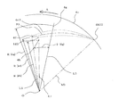
- (Blade leading edge) 4A shows the blade 4 viewed from the rotation center O in the radial direction (same as the direction of the arrow B shown in FIG. 3 and the direction perpendicular to the horizontal chord line S1), and FIG.
- the blade 4 is seen in the direction of the horizontal chord line S1 (the direction of the arrow C shown in FIG. 3).
- the blade leading edge 4a is roughly divided into a main plate side blade leading edge 4a1, a protruding blade leading edge 4a3, and a shroud side blade leading edge 4a2 from the main plate 2 toward the shroud 3.
- the main plate side blade front edge 4a1 includes a main plate side front edge vertical portion 40a1 which is a range perpendicular to the main plate 2, a main plate side front edge skirt portion 41a1 which is a predetermined range close to the main plate 2, and a main plate side front edge vertical. It is divided into a main plate side front edge inclined portion 42a1 which is bent at the portion 40a1 and the leading edge bending point 4h and is connected to the protruding blade leading edge 4a3.
- the large division of the main plate side blade leading edge 4a1 or the like, or the small division of the main plate side leading edge vertical portion 40a1 or the like is for convenience of explanation, and the boundary between them is not clearly shown. However, the range is not limited.
- the blade leading edge 4a gradually retreats from the main plate side front edge end point 4a11, which is a joint portion with the main plate 2, toward the blade trailing edge 4b in the main plate side front edge skirt portion 41a1 (direction in which the width of the blade becomes narrower).
- the main plate side front edge vertical portion 40a1 is perpendicular to the main plate 2 in the range from the end of the main plate side front edge skirt portion 41a1 to the front edge curve point 4h.
- the main plate side leading edge inclined portion 42a1 is bent at the leading edge bending point 4h and is moved forward in the direction opposite to the blade trailing edge 4b (the direction in which the blade width becomes wide), and eventually the protruding blade leading edge 4a3. It is connected to.
- the protruding blade leading edge 4a3 has a substantially arc shape and is connected to the protruding blade leading edge 4a3. Furthermore, the shroud 3 side of the protruding blade leading edge 4a3 is connected to the shroud-side blade leading edge 4a2. The shroud side blade leading edge 4a2 is further away from the main plate 2 as it approaches the blade trailing edge 4b, and is eventually connected to the shroud 3 at the shroud side front edge end point 4g.
- the blade trailing edge 4b is positioned on a virtual cylinder (virtual outer peripheral cylinder) formed by the main plate outer periphery 2b and the shroud outer periphery 3b, and from the main plate 2 toward the shroud 3, the main plate side blade trailing edge 4b1 and the shroud side blade rear Separated from the edge 4b2.
- the main plate side blade trailing edge 4 b 1 is a range perpendicular to the main plate 2.
- the shroud-side blade trailing edge 4b2 bends at the trailing edge curve point 4j, which is substantially the same distance from the main plate 2, and is positioned in a counter-rotating direction (direction in which the width of the blade 4 increases) as it approaches the shroud 3. Soon, it is connected to the shroud 3 at the shroud side rear edge end point 4b22.
- FIG. 6 shows a cross section at the leading edge curved point 4h, that is, a main plate side leading edge vertical portion 40a1 (the same as the range perpendicular to the main plate 2 of the blade leading edge 4a) and a trailing edge curved point 4j (the main plate 2 of the blade trailing edge 4b).
- the same as the range perpendicular to The leading edge bending point 4h is located at a distance R (4h) from the rotation center O.
- the trailing edge bending point 4j is positioned on the virtual outer peripheral cylinder (distance R (4j) from the rotation center O) at a position delayed by an angle ⁇ (4j) in the counter-rotating direction with respect to the leading edge bending point 4h. ing.
- the blade outer surface 4c1 is formed as a convex surface protruding in a direction far from the rotation center O.
- the blade inner surface 4d1 is formed in a convex surface protruding in a direction close to the rotation center O in a range close to the leading edge curved point 4h (same as close to the leading edge 4a), and close to the trailing edge curved point 4j (rear edge) In the same range, which is close to 4b, it is formed as a concave surface that recedes in a direction away from the rotation center O. That is, the radius of curvature when the blade outer surface 4c1 is regarded as an arc (actually not a circular arc) is smaller than the radius of curvature when the blade inner surface 4d1 is regarded as an arc (actually not a circular arc).
- the blade outer surface 4c1 is more greatly warped than the blade inner surface 4d1.
- a line connecting the centers of the blade outer surface 4c1 and the blade inner surface 4d1 is referred to as a “horizontal warp line P1”
- a straight line connecting the leading edge curved point 4h and the trailing edge curved point 4j is referred to as a “horizontal chord line S1”.
- FIG. 7A shows the cross-sectional shape of the joint between the main plate-side blade front edge 4a1 and the main plate 2, that is, the cross-section at the main plate-side front edge end point 4a11 and the main plate-side rear edge end point 4b11.
- FIG. 3 is an enlarged cross-sectional view of a part thereof.
- the main plate side front edge end point 4a11 is in a position (same as “advance”) advanced in the rotation direction A on the outer peripheral side with respect to the front edge curved point 4h.
- the blade outer surface 4c11 is formed as a convex surface protruding in a direction far from the rotation center O.
- the predetermined range close to the main plate side front edge end point 4a11 of the blade outer surface 4c11 deviates (deviations) from the blade inner surface 4d1 (range perpendicular to the main plate 2), and the range away from the main plate side front edge end point 4a11 is It is perpendicular to the main plate 2 and is the same as the blade outer surface 4c1.
- the blade inner surface 4d11 is formed in a convex surface protruding in a direction approaching the rotation center O in a predetermined range close to the main plate side front edge end point 4a11, and a range away from the main plate side front edge end point 4a11 is perpendicular to the main plate 2. However, it is the same as the blade inner surface 4d1.
- the blade outer surface 4c11 and the blade outer surface 4c1, and the blade inner surface 4d11 and the blade inner surface 4d1 are smoothly connected to form the main plate-side front edge skirt 41a1.
- FIG. 8 is a cross-section at the leading edge 4a3 of the protruding blade, and shows a cross-section at the shroud side rear edge end point 4b22.
- the protruding blade leading edge 4a3 is located at a position further in the rotational direction A on the outer peripheral side with respect to the leading edge curved point 4h.
- the protruding front edge end point 4f located on the outermost periphery of the protruding blade front edge 4a3 is a distance R (4f) larger than the distance R (4h) from the rotation center O.
- the shroud side rear edge end point 4b22 is on the virtual outer peripheral cylinder and is delayed by an angle ⁇ (4b22) in the counter-rotating direction. That is, the blade trailing edge 4b bends at the main plate side blade trailing edge 4b1 perpendicular to the main plate 2 and the trailing edge curved point 4j, and recedes in the counter-rotating direction (direction in which the width of the blade 4 increases) as it approaches the shroud 3. It has a shroud side blade trailing edge 4b2.
- the width of the blade 4 at this position is wider than the width of the cross section at the leading edge curved point 4h (same as the leading edge curved point 4h) by an amount equivalent to the angle “ ⁇ (4f) + ⁇ (4b22)”. It will be.
- the blade outer surface 4c3 is formed as a convex surface protruding in a direction far from the rotation center O.
- the blade inner surface 4d3 is formed in a convex surface protruding in a direction close to the rotation center O in the range close to the protruding front edge end point 4f (same as close to the front edge 4a), and close to the shroud side rear edge end point 4b22 (rear) In the same range close to the edge 4b), it is formed as a concave surface that recedes in a direction away from the rotation center O.
- a line connecting the center of the blade outer surface 4c3 and the blade inner surface 4d3 is referred to as a “horizontal warp line P3”, and a straight line connecting the protruding front edge end point 4f and the shroud side rear edge end point 4b22 is referred to as “horizontal chord line S3”.
- FIG. 9 is a cross section at the shroud side blade leading edge 4a2.
- a predetermined position 4i of the shroud side blade leading edge 4a2 is set to a distance R (4i) from the rotation center O, and an angle ⁇ (4i) is set to recede in the counter-rotating direction with respect to the protruding front edge end point 4f. ), The further the position 4i is away from the protruding front edge end point 4f, the more it moves backward in the counter-rotating direction and is positioned on the main plate outer periphery 2b.
- the range of the blade outer surface 4c and the blade inner surface 4d close to the shroud-side blade leading edge 4a2 has a substantially triangular shape bent in a substantially arc shape.
- the lines indicating the blade outer surface 4c and the blade inner surface 4d in the cross section including the position 4i are the blade outer surface 4c2 and the blade inner surface 4d2, and the line connecting the centers of the blade outer surface 4c2 and the blade inner surface 4d2 is “horizontal warp line P2”. Yes.
- the length of the horizontal warp line P2 becomes shorter as the position 4i is away from the main plate 2.
- FIG. 10 is a cross section at the shroud side blade leading edge 4a2.
- the shroud-side front edge end point 4g is retracted (delayed) by an angle ⁇ (4g) in the counter-rotating direction with respect to the protruding front edge end point 4f at a distance R (4g) from the rotation center O. . That is, there is a relationship of “R (4i) ⁇ R (4g), ⁇ (4i) ⁇ (4g)”. In summary, there is the following relationship.
- FIG. 11 is a cross-sectional view for explaining warpage at the blade leading edge 4a, and is a cross section of a plane perpendicular to the main plate 2 passing through the leading edge bending point 4h (more precisely, the main plate 2 and the horizontal chord line S1 (see FIG. 6). ) Is a vertical cross section).
- the perpendicular to the main plate 2 passing through the leading edge curved point 4 h is “perpendicular Q (4 h)”, and for convenience of explanation, the position 4 i happens to be located on the perpendicular Q (4 h).
- the center line (indicated by the alternate long and short dash line in the figure) between the blade outer surface 4c and the blade inner surface 4d is referred to as “vertical warp line Q (4i)”, and the intersection of the vertical warp line Q (4i) with the main plate 2 is referred to as “vertical warp line Q (4i)”.
- the range of the blade outer surface 4c that is equivalent to the main plate side front edge skirt 41a1 is inclined inward (right side in the figure) as the distance from the main plate 2 increases. ⁇ (4a12)> 90 °).
- the inclination angle ⁇ (4a12) formed with the main plate 2 is approximately 90 ° ( ⁇ (4a12) ⁇ 90. °). Therefore, the vertical warp line Q (4i) is inclined inward as the distance from the main plate 2 increases within a range equivalent to the main plate side front edge skirt 41a close to the main plate 2.
- the main plate side front edge vertical portion 40a1 further away from the main plate 2 is perpendicular to the main plate 2 and therefore coincides with the perpendicular Q (4h).
- the vertical warp line Q (4i) is inclined outward as the distance from the main plate 2 is further away from the vertical line Q (4h), and the inclination is gradually increased as the distance from the main plate 2 is increased. It becomes larger and has a substantially constant warpage angle ⁇ (4i) at the leading edge 4a3 of the protruding blade. Accordingly, in the blade 4, near the blade leading edge 4a, the blade outer surface 4c warps more than the blade inner surface 4d (when approximated to an arc, the former radius of curvature is smaller than the latter radius of curvature). .
- FIG. 12 is a cross-sectional view for explaining the warp in the blade middle part, and is a cross section of a plane perpendicular to the main plate 2 passing through the shroud-side front edge end point 4g (more precisely, the main plate 2 and the horizontal chord line S1 (see FIG. 6) ) Is a vertical cross section).
- a position that is in the plane of the main plate 2 and the horizontal chord line S1 passing through the shroud-side front edge point 4g and that is the same distance from the main plate 2 as the front edge curve point 4h is “intermediate curve point 4e”. It is said.
- the intermediate portion of the blade 4 is roughly divided into a main plate-side blade intermediate portion 4e1 close to the main plate 2 and a shroud-side blade intermediate portion 4e2 on the shroud 3 side, with the intermediate bending point 4e as a boundary.
- the main plate side blade intermediate portion 4e1 includes a main plate side intermediate skirt portion 41e1 which is a predetermined range close to the main plate 2, and a main plate side intermediate vertical portion 40e1 which is a range perpendicular to the main plate 2 and which is away from the main plate 2. Divided into small parts.
- the main plate side intermediate skirt portion 41e1, the main plate side intermediate vertical portion 40e1, and the shroud side blade intermediate portion 4e2 are smoothly connected, and the respective boundaries (intermediate bending points 4e) are not limited.
- a line perpendicular to the main plate 2 passing through the intermediate bending point 4e is defined as a perpendicular Q (4e).
- the center line (indicated by the alternate long and short dash line in the figure) between the blade outer surface 4c and the blade inner surface 4d is referred to as “vertical warp line Q (4g)”, and the intersection of the vertical warp line Q (4g) with the main plate 2 is referred to.
- the main plate side intermediate warp point 4a13 is referred to.
- the vertical warp line Q (4g) is inclined inward (right side in the figure) as the distance from the main plate 2 increases.
- the formed inclination angle ⁇ (4a13) is an obtuse angle ( ⁇ (4a13)> 90 °).
- the inclination angle ⁇ (4a13) formed with the main plate 2 is approximately 90 ° ( ⁇ (4a13) ⁇ 90 °. ).
- the vertical warp line Q (4 g) is inclined inward as the distance from the main plate 2 increases in a range close to the main plate 2.
- the main plate side intermediate vertical portion 40e1 further away from the main plate 2 is perpendicular to the main plate 2 and therefore coincides with the perpendicular Q (4e).
- the vertical warp line Q (4g) is inclined outward as the distance from the main plate 2 is further away from the perpendicular Q (4h), and the inclination is gradually increased as the distance from the main plate 2 is increased.
- the warpage angle ⁇ (4 g) is substantially constant.
- the warp angle ⁇ (4i) of the vertical warp line Q (4i) at the blade leading edge 4a (precisely, a position equivalent to the leading edge bending point 4h) is equal to the intermediate bending point 4e (the shroud side leading edge end point 4g).
- the warp angle ⁇ (4 g) of the vertical warp line Q (4 g) at the equivalent position) is larger. That is, the relationship is “( ⁇ (4i)> ⁇ (4g)”. In other words, the blade 4 is gradually approaching the rotation center O (blade leading edge 4a), and the warping angle in a range away from the main plate 2 is gradually increased.
- the flow flowing into the vicinity of the main plate 2 is the main plate 2 and the concave shape.
- concentration of the flow to the main plate 2 side is avoided and the wind speed is made uniform as a whole.
- the radius of curvature of the blade inner surface 4d can be considered to be larger than the radius of curvature of the blade outer surface 4c, so that the angle of attack with the flow flowing into the shroud-side blade leading edge 4a2 is reduced and smooth. Since it flows in, it is prevented from being peeled off and hardly disturbed.
- the warp angle ⁇ (4i) of the vertical warp line Q (4i) increases as it becomes closer to the rotation direction A (closer to the rotation center O) ( ⁇ (4i)> ⁇ (4g )), The shroud side blade leading edge 4a2 and the protruding blade leading edge 4a3 are warped (inclined) toward the rotation direction A side.
- the protruding front edge end point 4f is advanced in the rotational direction A and positioned farther from the rotation center O than the leading edge curved point 4h, and in the side view, the protruding front edge end point 4f is the main plate side front edge. Since the vertical portion 40a1 (same as the leading edge curved point 4h) advances in the rotation direction A, the protruding front edge end point 4f is the apex, the shroud side blade leading edge 4a2 and the protruding blade leading edge 4a3 (main plate side front) A “triangular wing shape” having two sides (including the edge inclined portion 42a1) is formed.
- downstream transition length of the vertical vortex generated in the vicinity of the curved portion of the main plate side front edge inclined portion 42a1 and the shroud side blade front edge 4a2 across the protruding blade leading edge 4a3 (the protruding front edge end point 4f) is too long. Therefore, a stable vortex is generated and the flow is not stably disturbed, so that the noise can be reduced.
- FIG. 13 is a cross-sectional view schematically illustrating the cross-sectional structure of the blade.
- the blade inner surface 4 d is substantially perpendicular to the main plate in a range closer to the main plate 2 than the line connecting the leading edge curved point 4 h and the trailing edge curved point 4 j, while the blade outer surface 4 c is separated from the main plate 2.
- the blade thickness which is the distance between the blade inner surface 4d and the blade outer surface 4c, becomes thinner as the distance from the main plate 2 increases (same as tapering).
- the blade 4 has a hollow structure in which a cavity 4v that opens to the lower surface of the main plate 2 is formed. Therefore, weight reduction can be promoted compared with the case where the blades 4 have a solid structure. Further, since the range close to the main plate 2 of the blades 4 is made of a two-plate structure made of plate-like members having substantially the same thickness as the main plate 2 or the shroud 3, it is easy to integrally mold the turbofan 1 with resin. .
- FIG. 13 and 14 schematically illustrate the trailing edge of the blade
- FIG. 13 is a side view
- FIG. 14 is a developed view in which the outer peripheral virtual cylinder is developed on a plane.
- the blade trailing edge 4b is located on a virtual outer peripheral cylinder (same as a virtual cylinder connecting the main plate outer periphery 2b and the shroud outer periphery 3b).
- the main plate side blade trailing edge 4b1 that is closer to the main plate 2 and less inclined with respect to the main plate 2 and the shroud 3 are located closer to the shroud 3 and closer to the shroud 3 (retracted) in the shroud side. It can be roughly divided into the blade trailing edge 4b2.
- the boundary between the two is not clear, and the position of the boundary is not limited.
- the angle formed by the blade outer surface 4c and the main plate 2 is the inclination angle ⁇ (4b1)
- the angle formed by the blade inner surface 4c and the main plate 2 is the inclination angle ⁇ ( 4b1).
- the main plate-side blade trailing edge 4b1 is the main plate 2 The one closer to is a broad trapezoidal shape.
- the angle formed by the blade outer surface 4c and the shroud 3 is the inclination angle ⁇ (4b2)
- the angle formed by the blade inner surface 4d and the shroud 3 is the inclination angle ⁇ (4b2).
- the shroud side blade trailing edge 4b2 has a substantially rectangular shape.
- the blade outer surface 4c in the range close to the main plate 2 of the main plate side blade trailing edge 4b1 is linearly approximated
- the blade outer surface 4c in the range near the shroud 3 of the shroud side blade trailing edge 4b2 is linearly approximated.
- the intersection point is “outer surface trailing edge curve point 4 kc”
- the blade outer surface 4 c is curved with a curve angle ⁇ (4 kc) around the outer surface trailing edge curve point 4 kc.
- the blade inner surface 4d in the range close to the main plate 2 of the main plate side blade trailing edge 4b1 is linearly approximated
- the blade inner surface 4d in the range close to the shroud 3 of the shroud side blade trailing edge 4b2 is linearly approximated.
- the blade inner surface 4 d is curved with a curve angle ⁇ (4 kd) around the inner surface trailing edge curve point 4 kd.
- the main plate-side blade trailing edge 4b1 has a substantially trapezoidal shape closer to the main plate 2, the blade outer surface 4c is substantially perpendicular to the main plate 2, and the blade inner surface 4d is inclined. A part of the flow toward the main plate 2 side where it is easy to concentrate is directed toward the inner surface trailing edge curved point 4 kd and the shroud 3. As a result, there is no local high-speed flow at the fan outlet 1b, the wind speed distribution becomes uniform, and the flow is stabilized against fluctuations in ventilation resistance. Therefore, the quality stability is improved with low noise and resistance to disturbance.
- the shroud side blade trailing edge 4b2 As the shroud side blade trailing edge 4b2 approaches the shroud 3, the shroud side blade trailing edge 4b2 is positioned in the counter-rotating direction (retreats). That is, in FIG. 8, the rotation center O and the trailing edge curved point 4j (same as the main plate side trailing edge end point 4b11) are formed by the radiation M1 and the radiation M3 connecting the rotation center O and the shroud side trailing edge end point 4b22.
- the angle ⁇ 2 is “5 ° to 10 °”. Therefore, if the angle ⁇ 2 is too small, the flow toward the main plate 2 side of the blade outer surface 4c is concentrated.
- the angle ⁇ 2 is too large, the flow is excessively attracted to the shroud 3 side, the wind speed on the shroud 3 side becomes high, and the wind speed distribution becomes uneven, resulting in noise deterioration. That is, if the angle ⁇ 2 is within the above range (5 ° ⁇ 2 ⁇ 10 °), the wind speed distribution is made uniform, and there is no noticeable high-speed range, so noise can be reduced.
- turbofan according to the present invention can reduce the noise by suppressing the separation and turbulence (vortex generation) of the air flow, it can be widely installed in various devices including a variety of air conditioners and air blowing means. Can do.
- SYMBOLS 1 Turbo fan (Embodiment 2), 1a: Fan suction inlet, 1b: Fan blower outlet, 2: Main plate, 2a: Boss, 2b: Main plate outer periphery, 3: Shroud, 3b: Shroud outer periphery, 4: Blade, 4a : Blade front edge, 4a1: main plate side blade front edge, 4a11: main plate side front edge end point, 4a12: main plate side front edge warp point, 4a13: main plate side intermediate warp point, 4a2: shroud side blade front edge, 4a3: protruding blade Front edge, 4b: Blade trailing edge, 4b1: Main plate side blade trailing edge, 4b11: Main plate side trailing edge end point, 4b2: Shroud side blade trailing edge, 4b22: Shroud side trailing edge end point, 4c: Blade outer surface, 4c1: Blade outer surface 4c11: blade outer surface, 4c2: blade outer surface, 4c2: blade outer
Landscapes
- Engineering & Computer Science (AREA)
- Mechanical Engineering (AREA)
- General Engineering & Computer Science (AREA)
- Physics & Mathematics (AREA)
- Geometry (AREA)
- Structures Of Non-Positive Displacement Pumps (AREA)
Abstract
Description
このようにターボファンを形成することで、流入空気の軸方向の速度成分が特に大きくなる羽根前縁側におけるシュラウド側の端部が、回転方向A側へ傾斜されて、流入する空気の流入方向に沿うようになるので、反回転方向側に生じやすい剥離を防ぎ、性能向上及び騒音の低減を図ることができる。
このようにターボファンを形成することで、羽根車出口における気流速度差に起因する乱流騒音を低減することができる。
このようにターボファンを形成することで、後縁部が直線状のものに対し後縁部での流れの合流に伴う空気流の圧力勾配及び速度欠損が小さくなり、乱れが抑制され低騒音化を図ることができる。
(i)特許文献1に開示されたターボファンは、羽根は前縁から後縁に渡り主板との接合端部に対し側板側の接合端部の位置が回転方向Aにオフセットし、シュラウド側羽根前縁が回転方向A側へ傾斜している。このため、流入する空気の流入方向に沿うようになるので、シュラウド側羽根前縁の反回転方向面側に生じやすい剥離を防ぐことができる。
しかし、羽根全体が回転方向Aに傾斜しているため、吸込流れが下流側へ向かうとき、主板側へ流れ易く、羽根側板側後縁部の近傍で剥離が生じて乱れや低風速域発生により風速分布が不均一となりうる。
また、羽根の回転方向A面は主板に対し鋭角で接合されているため、この接合部(角部)に流れが集中し易く、主板側の吹出風速も増加傾向となりうる。
そのため、乱れ発生や風速分布の不均一により、騒音悪化を招いてしまう。
さらに、羽根の回転軸に直交する水平断面において、回転中心Oを中心に任意同一半径における羽根の肉厚は、羽根車の高さ方向でほぼ同一のため、ABSやPsなど熱可塑性樹脂を材料に成形する場合、羽根は中実となるため重量が増加するおそれがある。
このため、羽根の回転方向A面は流れが主板側および側板側に集中し、中央付近が流れ難くなる。また、羽根の半回転方向A面は回転方向A面と略同一の略く字形状のため、隣り合う羽根の翼間距離は、羽根車の高さ方向で同一であり、回転方向A面で主板側および側板側に流れが集中する。このため、高さ方向の中央付近で流れが不安定となり剥離し、騒音悪化を招くおそれがある。
さらに、羽根の回転軸に直交する水平断面において、回転中心Oを中心に任意同一半径における羽根の肉厚は、羽根車の高さ方向でほぼ同一のため、ABSやPsなど熱可塑性樹脂を材料に成形する場合、羽根は中実となるため重量が増加するおそれがある。
該主板に対向して配置され、前記主板に近づく程、内径が拡大する拡径部を具備する筒状のシュラウドと、
両端がそれぞれ前記主板と前記シュラウドとに接合された複数枚の羽根と、を有するターボファンであって、
前記羽根の羽根後縁は、前記円盤の外周と前記シュラウドの外周とによって形成される仮想円筒上に位置し、前記羽根の羽根前縁は、前記羽根の羽根後縁よりも前記回転中心に近い位置にあり、且つ、 前記羽根後縁と前記羽根前縁とを結ぶ仮想線は、前記回転中心からの放射線に対して傾斜し、
前記羽根の前記回転中心から遠い面である羽根外面は、前記回転中心から遠ざかる方向に突出する凸面に形成され、
前記羽根前縁は、前記主板に近い主板側羽根前縁と、前記シュラウドに近いシュラウド側羽根前縁と、前記主板側羽根前縁と前記シュラウド側羽根前縁との間に形成された突出羽根前縁と、に区分され、
前記主板側羽根前縁の前記主板に近い範囲は、前記主板に近づく程、前記羽根後縁から遠ざかりながら、前記回転中心から遠ざかるように傾斜した主板側前縁裾野部を形成し、 該主板側前縁裾野部よりも前記主板から離れた範囲は、前記主板に垂直な主板側前縁垂直部を形成し、
該主板側前縁垂直部よりも前記主板から離れた範囲は、主板側前縁垂直部に対して、前記主板から遠ざかる程、前記羽根後縁から遠ざかりながら前記回転中心から遠ざかるように傾斜した主板側前縁傾斜部を形成し、
前記突出羽根前縁の突出前縁端点よりも前記主板に近い範囲は、主板側前縁傾斜部に繋がって、前記主板から遠ざかる程、前記羽根後縁から遠ざかりながら前記回転中心から遠ざかり、
前記突出羽根前縁の突出前縁端点よりも前記主板から遠い範囲は、シュラウド側羽根前縁に繋がって、前記主板から遠ざかる程、前記羽根後縁に近づきながら前記回転中心から遠ざかることを特徴とする。
また、主板側前縁裾野部(主板とのなす角が鈍角)を具備するので、主板近傍に流入する流れは、前記湾曲の中央付近(主板側前縁垂直部と主板側前縁傾斜部との接合位置に略相等する)に流れることから、主板側への流れの集中を回避することができる。よって、全体的に風速を均一化することが可能になる。
以上のように、本発明にかかるターボファンは、羽根間の通過風速の均一化、および羽根表面での剥離が防止可能になるため、低騒音化を図ることができる。
図1は本発明の実施の形態1に係る空気調和機を模式的に示す縦断面図である。図1において、天井埋込形空気調和機100は、部屋17の天井面18に形成された凹部19に埋め込まれるものであって、空調機本体10と、空調機本体10内に収納されたターボファン1および熱交換器16とを有している。
空調機本体10は、断面矩形状の筒体を形成する本体側板10bと、該筒体の一方の端面を塞ぐ矩形状の板材からなる本体天板10aと、から形成された函体であって、該函体の開口部(本体天板10aに対向する面)には、化粧パネル11が着脱自在に取付けられている。すなわち、本体天板10aは天井面18よりも上方に位置し、化粧パネル11は天井面18と略同一面に位置している。
一方、化粧パネル11の各辺に沿って、すなわち、吸込グリル11aを包囲するように、空気の吹出口であるパネル吹出口11bが形成され、パネル吹出口11bには吹き出す空気の方向を調整する風向ベーン13が設置されている。
そして、吸込グリル11aとターボファン1との間には、前者から後者に向かう吸込風路を形成するベルマウス14が配置され、ターボファン1の外周側を囲むように(例えば、平面視で略C字形状に)熱交換器16が配置されている。
熱交換器16は、略水平に所定の間隔を空けて配置されたフィンと、該フィンを貫通する伝熱管と、を有し、該伝熱管は室外機に接続配管(何れも図示しない)によって接続さ、冷却された冷媒または加熱された冷媒が供給される。
そして、ターボファン1では、下方から略上方に向かって吸い込まれた空気が、略水平方向に吹き出される。そうすると、吹き出された空気は、熱交換器16を通過しながら熱交換あるいは湿度調整された後、流れ方向を略下方に変更して、パネル吹出口11bから部屋17へ向けて吹き出される。このとき、パネル吹出口11bにおいて風向ベーン13によって風向が制御される。
すなわち、ターボファン1の本体吸込口10c側、又はパネル吹出口11b側、又は両方に通風可能な圧損体を有し、吸込口配設される圧損体が例えばフィルタ12の場合、長時間運転でホコリが堆積し通風抵抗が増加しても、羽根前縁4aが湾曲しているので剥離しづらく長時間運転でも低騒音を維持することができる。また、パネル吹出口11bに配設される圧損体が例えば熱交換器16や加湿ロータの場合、風速分布が均一なため熱交換器16や加湿ロータ全体で有効に熱交換や湿度放出ができる。また、熱交換器16が略四角形状でターボファン1と熱交換器16との距離が不均一であっても剥離しないため低騒音化を図ることができる(これについては、別途詳細に説明する)。
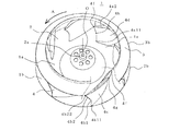
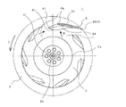
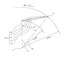
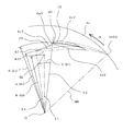
図2~図15は本発明の実施の形態2に係るターボファンを模式的に説明するものであって、図2は斜視図、図3は平面図、図4の(a)は一部を断面にした拡大側面図(図3に示す矢印B方向視)、図4の(b)は一部を断面にした拡大側面図(図3に示す矢印C方向視)、図5の(a)は羽根前縁を模式的に示す斜視図、図5の(b)は羽根後縁を模式的に示す斜視図、図6~図10はそれぞれ平面視の断面図、図11~図13はそれぞれ側面視の断面図、図14は羽根後縁を示す側面図、図15は羽根後縁を示す展開図である。
以下、ターボファン1として、空気調和機100(実施の形態1)に搭載されたものについて説明しているが、本発明はこれに限定されるものではなく、各種空気調和機や各種機器における送風手段として搭載されるものである。
なお、理解を容易にするため、図中上方を部屋17側にしている。すなわち、ターボファン1を天井面18から取り外し、本体天板10aを床面に載置し、本体吸込口10cを上にした状態に相等するから、図中上方から図中下方に向かって空気が吸い込まれることになっている。また、各図において同じ部分または相等する部分には同じ符号を付し、一部の説明を省略する。
図2~図5において、ターボファン1は、外周部が平坦で中央部が山状に突出した回転体である主板2と、主板2に対向した略円環状のシュラウド3と、一方の端部が主板2に、他方の端部がシュラウド3に接合された(一体的に形成されたに同じ)複数枚の羽根4と、から形成されている。
なお、図2および図3において斜線部は、シュラウド3を羽根4から剥ぎ取った際の状態、すなわち、シュラウド3と羽根4との接合境界面を示している。
シュラウド3は上縁がファン吸込口1aを形成し、ファン吸込口1aから下方になる程(主板2に近づく程)、内径が大きくなっている。
そして、シュラウド3の下縁(内径が最も大きくなっている。(以下、「シュラウド外周」と称す)3bと、これに対向する主板2の外周(以下、「主板外周」と称す)2bと、一対の羽根4の最も回転中心Oから離れた羽根後縁4bと、の4者は、同一の仮想円筒面(以下、「仮想外周円筒」と称す)上に位置し、ファン吹出口1bが形成されている(正確には、一対の羽根4に挟まれて形成されるから、羽根が7枚の場合、円周上に7箇所のファン吹出口1bが形成されている)。
図2~図5において、羽根4の羽根前縁4aは、回転中心Oから所定の距離に位置し、
羽根後縁4bは仮想外周円筒上に位置し、羽根前縁4aと羽根後縁4bとを結ぶ仮想線(以下、「弦線」と称している)は、回転中心Oからの放射線に対して傾斜している。
なお、以下の説明の便宜上、羽根後縁4bから遠ざかる方向を「回転方向A(図中、矢印Aにて示す)」と、羽根前縁4aから遠ざかる方向を「反回転方向」と称す。
また、羽根4の回転中心Oに近い方の面である羽根内面(負圧面に相当する)4dは、羽根外面4cと所定の間隔(羽根4の厚さに相等する)をとりながら同様の形態を呈している。このとき、前記所定の間隔(羽根4の厚さに相等する)は、羽根前縁4aと羽根後縁4bとの中間で厚くなり、両縁部に向かって除々に薄くなっている。すなわち、断面が翼形状に近似している。
なお、主板2に平行な面における、羽根外面4cと羽根内面4dとの中央位置を示す線を「水平反り線P」と称し、羽根前縁4aの端点と、羽根後縁4bの端点とを結ぶ直線を「水平弦線S」と称す。
図4の(a)は羽根4を回転中心Oから半径方向に向かって(図3において示す矢印Bの方向、水平弦線S1に垂直な方向に概略同じ)見、図4の(b)は羽根4を水平弦線S1の方向(図3において示す矢印Cの方向)に見ている。
羽根前縁4aは、主板2からシュラウド3に向かって、主板側羽根前縁4a1と、突出羽根前縁4a3と、シュラウド側羽根前縁4a2と、に大きく分けられる。そして、主板側羽根前縁4a1は、主板2に垂直な範囲である主板側前縁垂直部40a1と、主板2に近接した所定範囲である主板側前縁裾野部41a1と、主板側前縁垂直部40a1と前縁湾曲点4hにおいて折れ曲がり、突出羽根前縁4a3に繋がる主板側前縁傾斜部42a1と、に分けられる。
なお、主板側羽根前縁4a1等の大きな区分け、あるいは、主板側前縁垂直部40a1等の小さな区分けは、説明の便宜であって、相互の境界が明りょうに表れるものではなく、また、それぞれの範囲が限定されるものではない。
そして、主板側前縁傾斜部42a1は前縁湾曲点4hにおいて折れ曲がって、羽根後縁4bとは反対の方向に前進(羽根の幅が広くなる方向)し位置し、やがて、突出羽根前縁4a3に繋がっている。
突出羽根前縁4a3は略円弧状であって、突出羽根前縁4a3に繋がっている。さらに、突出羽根前縁4a3のシュラウド3側は、シュラウド側羽根前縁4a2に繋がっている。
シュラウド側羽根前縁4a2は、羽根後縁4bに近づく程、主板2から離れ、やがて、シュラウド3にシュラウド側前縁端点4gにおいて接続している。
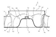
羽根後縁4bは、主板外周2bとシュラウド外周3bとが形成する仮想円筒(仮想外周円筒)上に位置し、主板2からシュラウド3に向かって、主板側羽根後縁4b1と、シュラウド側羽根後縁4b2と、分けられる。主板側羽根後縁4b1は、主板2に垂直な範囲である。シュラウド側羽根後縁4b2は、主板2からの距離が略同じである後縁湾曲点4jにおいて折れ曲がり、シュラウド3に近づく程、反回転方向(羽根4の幅が拡がる方向)に位置し(「後退する」に同じ)、やがて、シュラウド3にシュラウド側後縁端点4b22において接続している。
次に、羽根の断面形状について詳細に説明する。図6~図10は主板2に平行な面における羽根断面を示している。
図6は前縁湾曲点4hにおける断面、すなわち、主板側前縁垂直部40a1(羽根前縁4aの主板2に垂直な範囲に同じ)と、後縁湾曲点4j(羽根後縁4bの主板2に垂直な範囲に同じ)とを示している。
前縁湾曲点4hは回転中心Oから距離R(4h)に位置している。また、後縁湾曲点4jは、前縁湾曲点4hに対して反回転方向に角度θ(4j)だけ遅れた位置で、仮想外周円筒上(回転中心Oから距離R(4j))に位置している。
そして、羽根外面4c1は、回転中心Oから遠い方向に突出する凸面に形成されている。一方、羽根内面4d1は、前縁湾曲点4hに近い(前縁4aに近いに同じ)範囲では、回転中心Oに近い方向に突出する凸面に形成され、後縁湾曲点4jに近い(後縁4bに近いに同じ)範囲では、回転中心Oから遠ざかる方向に後退する凹面に形成されている。
すなわち、羽根外面4c1を円弧とみなした場合(実際は円弧でない)の曲率半径は、羽根内面4d1を円弧とみなした場合(実際は円弧でない)の曲率半径よりも小さくなっているから、水平断面において、羽根外面4c1の方が羽根内面4d1より、大きく反っていることになる。
このとき、羽根外面4c1と羽根内面4d1との中央を結ぶ線を「水平反り線P1」と、前縁湾曲点4hと後縁湾曲点4jとを結ぶ直線を「水平弦線S1」と称している。
図7の(a)は主板側羽根前縁4a1と主板2との接合部の断面形状、すなわち、主板側前縁端点4a11および主板側後縁端点4b11における断面を示し、図7の(b)はその一部を拡大した拡大断面図である。
主板側前縁端点4a11は前縁湾曲点4hに対して、より外周側で回転方向Aに進んだ位置(「前進する」に同じ)にある。すなわち、回転中心Oから、距離R(4h)よりも大きな距離R(4a11)に位置し、回転方向Aに角度θ(4a11)だけ進んでいる。また、主板側後縁端点4b11は後縁湾曲点4jと同じ位相に位置している。したがって、当該位置における羽根4の幅は角度θ(4a11)に相等する分だけ幅が広いことになる。
そして、羽根外面4c11は、回転中心Oから遠い方向に突出する凸面に形成されている。このとき、羽根外面4c11の主板側前縁端点4a11に近い所定範囲は、羽根内面4d1(主板2に垂直な範囲)から外れ(偏位し)、主板側前縁端点4a11から離れた範囲は、主板2に垂直であって、羽根外面4c1に同じになっている。
同様に、羽根内面4d11は、主板側前縁端点4a11に近い所定範囲は、回転中心Oに近づく方向に突出する凸面に形成され、主板側前縁端点4a11から離れた範囲は、主板2に垂直であって、羽根内面4d1に同じになっている。
そして、羽根外面4c11と羽根外面4c1、および羽根内面4d11と羽根内面4d1とは滑らかに繋がり、主板側前縁裾野部41a1を形成している。
図8は突出羽根前縁4a3における断面であって、シュラウド側後縁端点4b22における断面を示している。
突出羽根前縁4a3は前縁湾曲点4hに対して、より外周側で回転方向Aに進んだ位置にある。このとき、突出羽根前縁4a3の最も外周に位置する(回転方向Aに最も進んだ位置に同じ)突出前縁端点4fは、回転中心Oから、距離R(4h)よりも大きな距離R(4f)に位置し、回転方向Aに角度θ(4f)だけ進んでいる。
すなわち、主板2から離れるに伴って、主板側前縁傾斜部42a1および突出羽根前縁4a3は、前縁湾曲点4hに対して除々に「外周側かつ回転方向A側」に位置しながら、最も回転方向Aに進んだ位置である突出前縁端点4fに繋がっている。
したがって、当該位置における羽根4の幅は角度「θ(4f)+θ(4b22)」に相等する分だけ、前縁湾曲点4h(前縁湾曲点4hに同じ)における断面の幅より、幅が広いことになる。
そして、羽根外面4c3は、回転中心Oから遠い方向に突出する凸面に形成されている。一方、羽根内面4d3は、突出前縁端点4fに近い(前縁4aに近いに同じ)範囲では、回転中心Oに近い方向に突出する凸面に形成され、シュラウド側後縁端点4b22に近い(後縁4bに近いに同じ)範囲では、回転中心Oから遠ざかる方向に後退する凹面に形成されている。
このとき、羽根外面4c3と羽根内面4d3との中央を結ぶ線を「水平反り線P3」と突出前縁端点4fとシュラウド側後縁端点4b22とを結ぶ直線を「水平弦線S3」と、称す。
図9はシュラウド側羽根前縁4a2における断面である。図9において、シュラウド側羽根前縁4a2の所定の位置4iを、回転中心Oからの距離を距離R(4i)、突出前縁端点4fに対して反回転方向に後退する角度を角度θ(4i)とすると、位置4iが突出前縁端点4fから離れる程、反回転方向に後退し、且つ、主板外周2bに位置している。
すなわち、位置4iが主板2から離れる程(シュラウド3に近づく程に同じ)、角度θ(4i)および距離R(4i)が除々に大きくなっている。したがって、羽根外面4cおよび羽根内面4dのシュラウド側羽根前縁4a2に近い範囲は、略円弧状に曲げられた略三角形状を呈している。
そして、位置4iを含む断面における羽根外面4cおよび羽根内面4dを示す線を、羽根外面4c2および羽根内面4d2とし、羽根外面4c2と羽根内面4d2との中央を結ぶ線を「水平反り線P2」としている。このとき、位置4iを含む断面の回転中心Oから遠い側は、シュラウド3に接しているから、位置4iが主板2から離れる程、水平反り線P2の長さは短くなる。
図10はシュラウド側羽根前縁4a2における断面である。図9において、シュラウド側前縁端点4gは、回転中心Oから距離R(4g)で、突出前縁端点4fに対して反回転方向に角度θ(4g)だけ後退している(遅れている)。すなわち、「R(4i)<R(4g)、θ(4i)<θ(4g)」の関係にある。
以上をまとめると、次の関係がある。
「R(4a11)>R(4h)」、
「R(4h)<R(4f)<R(4i)<R(4g)」、
「θ(4a11)≠0」、
「θ(4f)≠0」、
「0≠θ(4i)<θ(4g)」。
図11は羽根前縁4aにおける反りを説明する断面図であって、前縁湾曲点4hを通過する主板2に垂直な面の断面(正確には、主板2および水平弦線S1(図6参照)に垂直な断面)を示している。
図11において、前縁湾曲点4hを通過する主板2への垂線を「垂線Q(4h)」とし、説明の便宜上、位置4iが、たまたま垂線Q(4h)上に位置しているとしている。そして、羽根外面4cと羽根内面4dとの中央線(図中、一点鎖線にて示す)を「垂直反り線Q(4i)」と称し、垂直反り線Q(4i)の主板2との交点を、主板側前縁反り点4a12とする。
したがって、垂直反り線Q(4i)は、主板2に近い主板側前縁裾野部41aに相等する範囲において、主板2から離れる程、内側に傾いている。そして、主板2からより離れた主板側前縁垂直部40a1においては、主板2に垂直であるから、垂線Q(4h)に一致している。
さらに、主板側前縁傾斜部42a1においては、垂直反り線Q(4i)は垂線Q(4h)に対して主板2から離れる程、外側に傾斜し、該傾斜は主板2から離れる程、除々に大きくなり、突出羽根前縁4a3において略一定の反り角度α(4i)になっている。
したがって、羽根4は羽根前縁4aの近くにおいて、羽根外面4cの方が羽根内面4dよりも大きく反っている(円弧に近似した場合、前者の曲率半径が後者の曲率半径より小さくなっている)。
図12は羽根中間部における反りを説明する断面図であって、シュラウド側前縁端点4gを通過する主板2に垂直な面の断面(正確には、主板2および水平弦線S1(図6参照)に垂直な断面)を示している。
図12において、シュラウド側前縁端点4gを通過する主板2および水平弦線S1な面内にあって、主板2からの距離が前縁湾曲点4hと同じである位置を「中間湾曲点4e」としている。
このとき、羽根4の中間部は、中間湾曲点4eを境に、主板2に近い主板側羽根中間部4e1と、シュラウド3側のシュラウド側羽根中間部4e2と、に大きく分けられる。また、主板側羽根中間部4e1は、主板2に近接した所定範囲である主板側中間裾野部41e1と、主板2から離れた、主板2に垂直な範囲である主板側中間垂直部40e1と、に小さく分けられる。
羽根外面4cの主板2に近い主板側中間裾野部41e1の範囲では、垂直反り線Q(4g)は、主板2から離れる程、内側(図中、右側)に傾いているから、主板2とのなす傾斜角度β(4a13)は鈍角(β(4a13)>90°)である。一方、羽根内面4dの主板側中間垂直部40e1に相等する範囲は、主板2の略垂直であるから、主板2とのなす傾斜角度δ(4a13)は略90°(δ(4a13)≒90°)である。
さらに、シュラウド側羽根中間部4e2においては、垂直反り線Q(4g)は垂線Q(4h)に対して主板2から離れる程、外側に傾斜し、該傾斜は主板2から離れる程、除々に大きくなり、シュラウド3に近い範囲では、略一定の反り角度α(4g)になっている。
すなわち、羽根4は回転中心O(羽根前縁4a)に近づく略、主板2から離れた範囲の反り角度が除々に大きくなっている。
(イ)羽根前縁4aに近い範囲は、平面視において、羽根外面4c1の方が羽根内面4d1よりも大きく反っている形態(前者の曲率半径の方が後者の曲率半径よりも小さいに相等する)のため、ターボファン1が誘引する吸込流れの誘引を促進している。
(ロ)主板側前縁端点4a11が、平面視において、主板側前縁端点4a11が主板側前縁垂直部40a1(前縁湾曲点4hに同じ)よりも回転方向Aに前進して回転中心Oよりも遠くに位置し、側面視において、主板側前縁裾野部41a1と主板2とがなす傾斜角度β(4a12)が鈍角であるから、主板2の近傍に流入する流れは主板2及び凹形状に湾曲する羽根車高さ方向の中央付近の最もへこむ部分とに流れることで主板2側への流れの集中を回避し全体的に風速を均一化している。
(ニ)側面視において、垂直反り線Q(4i)の反り角度α(4i)は、回転方向A側になる程(回転中心Oに近づく程)、大きくなる(α(4i)>α(4g))から、シュラウド側羽根前縁4a2および突出羽根前縁4a3は、回転方向A側になる程、反っている(傾斜している)。
また、平面視において、突出前縁端点4fが前縁湾曲点4hよりも回転方向Aに前進して回転中心Oよりも遠くに位置し、側面視において、突出前縁端点4fが主板側前縁垂直部40a1(前縁湾曲点4hに同じ)よりも回転方向Aに前進しているから、突出前縁端点4fを頂点とし、シュラウド側羽根前縁4a2と、突出羽根前縁4a3(主板側前縁傾斜部42a1を含む)を二辺とする「三角翼形状」が形成される。
(ヘ)以上の結果、羽根4間の通過風速の均一化及び羽根表面における剥離を防止することが可能になるため、低騒音化を図ることができる。
図13は羽根の断面構造を模式的に説明する断面図である。羽根4は、前縁湾曲点4hおよび後縁湾曲点4jを結ぶ線よりも主板2側の範囲において、羽根内面4dは主板に略垂直であるのに対し、羽根外面4cは主板2から離れる程、回転中心O側に傾いている。すなわち、羽根内面4dと羽根外面4cとの距離である羽根厚さは、主板2から遠ざかる程、薄くなっている(先細りに同じ)。
このことは、一方の羽根4の羽根外面4cと羽根4に隣接する他方の羽根の羽根内面4dとの距離が、主板2から離れる程、広くなっていることに同じであるから、主板2側への流れの集中を回避することができ、風速が均一化され、低騒音化を図ることができる。
また、羽根4は、主板2の下面に開口する空洞4vが内部に形成された中空構造になっている。したがって、羽根4を中実構造にした場合に比べ、軽量化を促進することができる。また、羽根4の主板2に近い範囲を、主板2あるいはシュラウド3と略同じ厚さの板状部材からなる二枚構造にするから、ターボファン1を一体的に樹脂成形することが容易になる。
図13および図14は羽根後縁を模式的に説明するものであって、図13は側面図、図14は外周仮想円筒を平面に展開した展開図である。
図13および図14において、羽根後縁4bは、仮想外周円筒(主板外周2bとシュラウド外周3bとを結ぶ仮想円筒に同じ)上に位置している。そして、主板2寄りであって、主板2に対して傾斜の少ない主板側羽根後縁4b1と、シュラウド3寄りであって、シュラウド3に近づく程、反回転方向に位置する(後退する)シュラウド側羽根後縁4b2とに、概略分けることができる。なお、両者の境界は明りょうでなく、該境界の位置は限定するものではない。
また、シュラウド側羽根後縁4b2に相等する範囲において、羽根外面4cとシュラウド3とがなす角度を傾斜角度β(4b2)と、羽根内面4dとシュラウド3とがなす角度を傾斜角度δ(4b2)とする。このとき、傾斜角度β(4b2)と傾斜角度δ(4b2)は略同じであるから、シュラウド側羽根後縁4b2は略矩形状を呈している。
同様に、主板側羽根後縁4b1の主板2に近い範囲の羽根内面4dを直線近似し、シュラウド側羽根後縁4b2のシュラウド3に近い範囲の羽根内面4dを直線近似し、かかる2本の直線の交点を「内面後縁湾曲点4kd」とすると、羽根内面4dは、内面後縁湾曲点4kdを中心に、湾曲角度φ(4kd)でもって湾曲している。このとき、
「φ(4kc)=β(4b1)+β(4b2)」、
「φ(4kd)=δ(4b1)+δ(4b2)」、
「180°>φ(4kc)>φ(4kd)」、
の関係がある。さらに、外面後縁湾曲点4kcが、内面後縁湾曲点4kdよりも回転方向Aに前進した位置になっている。
(あ)羽根外面4cにおいて、羽根4が外面後縁湾曲点4kcで湾曲し、シュラウド側羽根後縁4b2に対し主板側羽根後縁4b1は直立形態である。したがって、全体が回転方向Aに対し後退する形状で、主板2からシュラウド3側への圧力勾配により流れの一部がシュラウド3側へ向かう際、主板2側がシュラウド3側に対し相対的に圧力上昇する。このため、さらにシュラウド3側へ流れを誘引し、通風抵抗が変動してもシュラウド側羽根後縁4b2での剥離域が生じづらくなる。
(い)前記のように、主板側羽根後縁4b1は主板2に近い方が広い略台形状を呈、羽根外面4cが主板2に略垂直で、羽根内面4dが傾斜しているから、流れが集中しやすい主板2側へ向かう流れの一部が、内面後縁湾曲点4kdやシュラウド3方向へ向かうようになる。その結果、ファン吹出口1bで局所的な高速流がなくなり、風速分布が均一化すると共に、通風抵抗の変動に対しても流れが安定する。よって、低騒音で外乱に強く品質安定性が良くなる。
したがって、角度θ2が小さ過ぎると、羽根外面4cの主板2側に向かう流れが集中する。一方、角度θ2が大き過ぎると、シュラウド3側に流れが誘引され過ぎ、シュラウド3側の風速が高くなり、風速分布が不均一となるため騒音悪化してしまう。すなわち、角度θ2が前記範囲(5°<θ2<10°)であれば、風速分布が均一化され、目だった高速域が無くなるため低騒音化を図ることができる。
Claims (8)
- 中心に回転中心と、該回転中心の近くに形成された突出するボスと、を具備する円盤状の主板と、
該主板に対向して配置され、前記主板に近づく程、内径が拡大する拡径部を具備する筒状のシュラウドと、
両端がそれぞれ前記主板と前記シュラウドとに接合された複数枚の羽根と、を有するターボファンであって、
前記羽根の羽根後縁は、前記円盤の外周と前記シュラウドの外周とによって形成される仮想円筒上に位置し、前記羽根の羽根前縁は、前記羽根の羽根後縁よりも前記回転中心に近い位置にあり、且つ、 前記羽根後縁と前記羽根前縁とを結ぶ仮想線は、前記回転中心からの放射線に対して傾斜し、
前記羽根の前記回転中心から遠い面である羽根外面は、前記回転中心から遠ざかる方向に突出する凸面に形成され、
前記羽根前縁は、前記主板に近い主板側羽根前縁と、前記シュラウドに近いシュラウド側羽根前縁と、前記主板側羽根前縁と前記シュラウド側羽根前縁との間に形成された突出羽根前縁と、に区分され、
前記主板側羽根前縁の前記主板に近い範囲は、前記主板に近づく程、前記羽根後縁から遠ざかりながら、前記回転中心から遠ざかるように傾斜した主板側前縁裾野部を形成し、 該主板側前縁裾野部よりも前記主板から離れた範囲は、前記主板に垂直な主板側前縁垂直部を形成し、
該主板側前縁垂直部よりも前記主板から離れた範囲は、主板側前縁垂直部に対して、前記主板から遠ざかる程、前記羽根後縁から遠ざかりながら前記回転中心から遠ざかるように傾斜した主板側前縁傾斜部を形成し、
前記突出羽根前縁の突出前縁端点よりも前記主板に近い範囲は、主板側前縁傾斜部に繋がって、前記主板から遠ざかる程、前記羽根後縁から遠ざかりながら前記回転中心から遠ざかり、
前記突出羽根前縁の突出前縁端点よりも前記主板から遠い範囲は、シュラウド側羽根前縁に繋がって、前記主板から遠ざかる程、前記羽根後縁に近づきながら前記回転中心から遠ざかることを特徴とするターボファン。 - 前記主板に垂直な面における羽根外面と羽根内面との中央線である垂直反り線と、前記主板に垂直な垂線とが、前記主板から離れた範囲で形成する反り角度が、前記羽根後縁から遠ざかる程、除々に大きくなることを特徴とする請求項1記載のターボファン。
- 前記羽根後縁は、前記主板に近い主板側羽根後縁と、前記シュラウドに近いシュラウド側羽根後縁とに区分され、
前記主板側羽根後縁は前記主板に略垂直で、
前記シュラウド側羽根後縁は、前記主板から遠ざかる程、除々に前記羽根前縁から遠ざかるように傾斜していることを特徴とする請求項1または2記載のターボファン。 - 平面視において、前記主板側羽根後縁と前記主板との交点である主板側後縁端点と前記回転中心とを結ぶ放射線と、前記シュラウド側羽根後縁と前記シュラウドとの交点であるシュラウド側後縁端点と前記回転中心とを結ぶ放射線と、がなす角度が、5°~10°であることを特徴とする請求項3記載のターボファン。
- 前記主板側前縁垂直部における前記羽根の水平弦線(S1)と、前記突出前縁端点における前記羽根の水平弦線(S3)とがなす角度が、0°~10°であることを特徴とする請求項1乃至4の何れかに記載のターボファン。
- 前記羽根は、前記主板を貫通して開口する空洞を具備する中空構造であって、前記羽根外面と前記羽根内面との距離は、前記主板から遠ざかる程、除々に小さくなることを特徴とする請求項1乃至5の何れかに記載のターボファン。
- 前記羽根後縁の前記主板に近い範囲における前記一方の羽根の羽根外面と該一方の羽根に隣接する他方の羽根の羽根内面との羽根間隔が、前記羽根後縁の前記主板から遠い範囲における前記一方の羽根の羽根外面と該一方の羽根に隣接する他方の羽根の羽根内面との羽根間隔よりも、小さいことを特徴とする請求項1乃至6の何れかに記載のターボファン。
- 一方の面に、空気の吸込口および吹出口が形成された本体と、
前記吸込口に連通して前記本体内に配置された請求項1乃至7の何れかに記載のターボファンと、
該ターボファンと前記吹出口との間に配置された空気調和手段と、
を有することを特徴とする空気調和機。
Priority Applications (6)
| Application Number | Priority Date | Filing Date | Title |
|---|---|---|---|
| US13/319,804 US8834121B2 (en) | 2009-06-11 | 2010-03-16 | Turbo fan and air conditioning apparatus |
| EP10785873.0A EP2441963B1 (en) | 2009-06-11 | 2010-03-16 | Turbofan and air conditioner |
| ES10785873.0T ES2647955T3 (es) | 2009-06-11 | 2010-03-16 | Turboventilador y aparato de aire acondicionado |
| CN201080025499.1A CN102459917B (zh) | 2009-06-11 | 2010-03-16 | 涡轮风扇及空调机 |
| EP17181936.0A EP3273067B1 (en) | 2009-06-11 | 2010-03-16 | Turbofan and air conditioner |
| US14/454,201 US9651056B2 (en) | 2009-06-11 | 2014-08-07 | Turbo fan and air conditioning apparatus |
Applications Claiming Priority (2)
| Application Number | Priority Date | Filing Date | Title |
|---|---|---|---|
| JP2009139986A JP5164932B2 (ja) | 2009-06-11 | 2009-06-11 | ターボファンおよび空気調和機 |
| JP2009-139986 | 2009-06-11 |
Related Child Applications (2)
| Application Number | Title | Priority Date | Filing Date |
|---|---|---|---|
| US13/319,804 A-371-Of-International US8834121B2 (en) | 2009-06-11 | 2010-03-16 | Turbo fan and air conditioning apparatus |
| US14/454,201 Division US9651056B2 (en) | 2009-06-11 | 2014-08-07 | Turbo fan and air conditioning apparatus |
Publications (1)
| Publication Number | Publication Date |
|---|---|
| WO2010143341A1 true WO2010143341A1 (ja) | 2010-12-16 |
Family
ID=43308604
Family Applications (1)
| Application Number | Title | Priority Date | Filing Date |
|---|---|---|---|
| PCT/JP2010/001874 Ceased WO2010143341A1 (ja) | 2009-06-11 | 2010-03-16 | ターボファンおよび空気調和機 |
Country Status (6)
| Country | Link |
|---|---|
| US (2) | US8834121B2 (ja) |
| EP (2) | EP2441963B1 (ja) |
| JP (1) | JP5164932B2 (ja) |
| CN (2) | CN102459917B (ja) |
| ES (2) | ES2647955T3 (ja) |
| WO (1) | WO2010143341A1 (ja) |
Cited By (2)
| Publication number | Priority date | Publication date | Assignee | Title |
|---|---|---|---|---|
| EP2426362A3 (en) * | 2010-09-02 | 2012-10-17 | LG Electronics, Inc. | Turbo fan and air conditioner with turbo fan |
| CN113074127A (zh) * | 2020-01-06 | 2021-07-06 | 广东威灵电机制造有限公司 | 送风装置及吸尘器 |
Families Citing this family (38)
| Publication number | Priority date | Publication date | Assignee | Title |
|---|---|---|---|---|
| JP5164932B2 (ja) * | 2009-06-11 | 2013-03-21 | 三菱電機株式会社 | ターボファンおよび空気調和機 |
| JP5730649B2 (ja) * | 2011-04-13 | 2015-06-10 | 株式会社日立製作所 | 羽根車及びそれを有するターボ機械 |
| CN103511335B (zh) * | 2012-06-25 | 2016-08-24 | 珠海格力电器股份有限公司 | 空调、离心风机及其叶片 |
| WO2014061094A1 (ja) | 2012-10-16 | 2014-04-24 | 三菱電機株式会社 | ターボファンおよび空気調和機 |
| JP5522306B1 (ja) * | 2012-12-21 | 2014-06-18 | ダイキン工業株式会社 | 遠心ファン |
| KR102076684B1 (ko) * | 2013-02-21 | 2020-02-12 | 엘지전자 주식회사 | 터보팬 및 이를 사용한 천정형 공기조화기 |
| CN103195751B (zh) * | 2013-04-03 | 2015-11-04 | 宁波朗迪叶轮机械有限公司 | 后倾式离心风叶 |
| EP2985542A4 (en) * | 2013-04-30 | 2017-04-05 | Daikin Industries, Ltd. | Decorative panel and air-conditioner in-room unit provided with same |
| JP5783214B2 (ja) * | 2013-09-30 | 2015-09-24 | ダイキン工業株式会社 | 遠心送風機及びこれを備えた空気調和機 |
| CN104564805B (zh) * | 2013-10-29 | 2017-11-10 | 海尔集团公司 | 一种离心风机的扇叶结构、离心风机及嵌入式空调内机 |
| KR102203935B1 (ko) | 2014-01-08 | 2021-01-18 | 삼성전자주식회사 | 토출구 개폐장치 및 이를 포함하는 공기조화기 |
| CN104895835B (zh) * | 2014-03-05 | 2017-11-28 | 海尔集团公司 | 一种离心风扇、离心风扇的制造方法及具有该离心风扇的空调 |
| JP2016084751A (ja) * | 2014-10-27 | 2016-05-19 | 三菱重工業株式会社 | インペラ、遠心式流体機械、及び流体装置 |
| DE102015101938A1 (de) * | 2015-02-11 | 2016-08-11 | Ebm-Papst Mulfingen Gmbh & Co. Kg | Ventilatorrad und Ventilator |
| US10641280B2 (en) * | 2015-05-22 | 2020-05-05 | Samsung Electronics Co., Ltd. | Turbo fan and air conditioner including same |
| CN106337833A (zh) * | 2015-07-06 | 2017-01-18 | 杭州三花研究院有限公司 | 叶轮、离心泵以及电驱动泵 |
| ITUB20152807A1 (it) * | 2015-08-03 | 2017-02-03 | Ma Ti Ka S R L | Ventola per forni per la cottura di alimenti |
| KR102403728B1 (ko) * | 2015-10-07 | 2022-06-02 | 삼성전자주식회사 | 공기조화장치용 터보팬 |
| WO2017106530A1 (en) * | 2015-12-16 | 2017-06-22 | Daniel Khalitov | Air jet device and method |
| JP6593539B2 (ja) * | 2016-07-27 | 2019-10-23 | 株式会社デンソー | 遠心送風機 |
| CN106640748B (zh) * | 2017-01-06 | 2022-12-02 | 珠海格力电器股份有限公司 | 叶片、叶轮及风机 |
| JP2018150910A (ja) * | 2017-03-14 | 2018-09-27 | ダイキン工業株式会社 | 両吸込型遠心ファン |
| DE102018204978A1 (de) * | 2018-04-03 | 2019-10-10 | Siemens Healthcare Gmbh | Kühlsystem für eine Bildgebungsvorrichtung mit einer Gantry |
| JP7207933B2 (ja) * | 2018-10-15 | 2023-01-18 | 日立建機株式会社 | 建設機械 |
| EP3647603A1 (en) | 2018-10-31 | 2020-05-06 | Carrier Corporation | Arrangement of centrifugal impeller of a fan for reducing noise |
| CN109899318B (zh) * | 2019-02-22 | 2021-03-30 | 宁波德业日用电器科技有限公司 | 新健康空气净化器的旋涡风扇 |
| CN110566500B (zh) * | 2019-10-12 | 2024-08-16 | 浙江科贸智能机电股份有限公司 | 一种离心通风机的叶轮 |
| JP2021134678A (ja) * | 2020-02-25 | 2021-09-13 | 三菱重工業株式会社 | 遠心圧縮機 |
| DE102020114389A1 (de) * | 2020-05-28 | 2021-12-02 | Ebm-Papst Mulfingen Gmbh & Co. Kg | Gebläserad mit ener nahtlosen Anbindung der Laufradschaufeln an einen Scheibenkörper |
| DE102020114387A1 (de) * | 2020-05-28 | 2021-12-02 | Ebm-Papst Mulfingen Gmbh & Co. Kg | Gebläserad mit dreidimensional gekrümmten Laufradschaufeln |
| US11686315B2 (en) * | 2020-08-11 | 2023-06-27 | Hunter Fan Company | Ceiling fan and impeller blade |
| WO2022055112A1 (ko) * | 2020-09-09 | 2022-03-17 | 삼성전자주식회사 | 팬, 팬을 갖는 공기조화기 및 팬의 제조방법 |
| CN116507808B (zh) * | 2020-11-25 | 2025-04-22 | 三菱电机株式会社 | 涡轮风扇以及空调机 |
| CN112392547A (zh) * | 2020-11-30 | 2021-02-23 | 中国航发动力股份有限公司 | 一种旋转机械的转子连接结构 |
| US20240209755A1 (en) * | 2021-06-03 | 2024-06-27 | Howard Purdum | Reaction turbine operating on condensing vapors |
| JP7697401B2 (ja) * | 2022-04-21 | 2025-06-24 | 株式会社デンソー | 送風機 |
| CN116592460B (zh) * | 2023-04-19 | 2026-01-23 | 安徽奥克斯智能电气有限公司 | 摆风控制方法、装置、空调器及存储介质 |
| US12510097B1 (en) | 2024-08-14 | 2025-12-30 | Regal Beloit America, Inc. | Axial fan and housing assembly and methods of use thereof |
Citations (6)
| Publication number | Priority date | Publication date | Assignee | Title |
|---|---|---|---|---|
| JPH05312191A (ja) * | 1992-03-11 | 1993-11-22 | Daikin Ind Ltd | 遠心ファン |
| JP3092554B2 (ja) | 1997-09-30 | 2000-09-25 | ダイキン工業株式会社 | 遠心送風機及びその製造方法並びに該遠心送風機を備えた空気調和機 |
| JP2006002689A (ja) * | 2004-06-18 | 2006-01-05 | Hitachi Home & Life Solutions Inc | 送風機 |
| JP3861008B2 (ja) | 2002-01-10 | 2006-12-20 | 三菱重工業株式会社 | ターボファン及びそれを備えた空気調和装置 |
| JP2007205269A (ja) | 2006-02-02 | 2007-08-16 | Daikin Ind Ltd | 遠心ファン |
| JP2008002379A (ja) * | 2006-06-23 | 2008-01-10 | Daikin Ind Ltd | 遠心ファン |
Family Cites Families (12)
| Publication number | Priority date | Publication date | Assignee | Title |
|---|---|---|---|---|
| CH512703A (it) * | 1969-08-07 | 1971-09-15 | Riello Condizionatori S A S | Apparecchio condizionatore, per il condizionamento ambientale di locali |
| US4231706A (en) * | 1977-04-27 | 1980-11-04 | Hitachi, Ltd. | Impeller of a centrifugal blower |
| JP2730396B2 (ja) | 1992-05-13 | 1998-03-25 | ダイキン工業株式会社 | 遠心ファンの羽根車 |
| JP2730395B2 (ja) | 1992-05-13 | 1998-03-25 | ダイキン工業株式会社 | 空気調和装置 |
| DE4311746A1 (de) * | 1993-04-08 | 1994-10-13 | Klein Schanzlin & Becker Ag | Kreiselpumpenlaufrad |
| US5478201A (en) * | 1994-06-13 | 1995-12-26 | Carrier Corporation | Centrifugal fan inlet orifice and impeller assembly |
| US6338610B1 (en) * | 1998-01-14 | 2002-01-15 | Ebara Corporation | Centrifugal turbomachinery |
| US6042335A (en) * | 1998-05-04 | 2000-03-28 | Carrier Corporation | Centrifugal flow fan and fan/orifice assembly |
| JP2001159396A (ja) * | 1999-12-03 | 2001-06-12 | Daikin Ind Ltd | 遠心ファン及び該遠心ファンを備えた空気調和機 |
| KR100405981B1 (ko) * | 2001-02-12 | 2003-11-14 | 엘지전자 주식회사 | 천정형 공조기의 터보팬 구조 |
| JP2003090298A (ja) * | 2001-09-17 | 2003-03-28 | Nippon Soken Inc | 遠心ファン |
| JP5164932B2 (ja) * | 2009-06-11 | 2013-03-21 | 三菱電機株式会社 | ターボファンおよび空気調和機 |
-
2009
- 2009-06-11 JP JP2009139986A patent/JP5164932B2/ja not_active Expired - Fee Related
-
2010
- 2010-03-16 WO PCT/JP2010/001874 patent/WO2010143341A1/ja not_active Ceased
- 2010-03-16 CN CN201080025499.1A patent/CN102459917B/zh not_active Expired - Fee Related
- 2010-03-16 ES ES10785873.0T patent/ES2647955T3/es active Active
- 2010-03-16 EP EP10785873.0A patent/EP2441963B1/en not_active Not-in-force
- 2010-03-16 EP EP17181936.0A patent/EP3273067B1/en not_active Not-in-force
- 2010-03-16 CN CN201510144533.1A patent/CN104791298A/zh active Pending
- 2010-03-16 ES ES17181936T patent/ES2794580T3/es active Active
- 2010-03-16 US US13/319,804 patent/US8834121B2/en active Active
-
2014
- 2014-08-07 US US14/454,201 patent/US9651056B2/en not_active Expired - Fee Related
Patent Citations (6)
| Publication number | Priority date | Publication date | Assignee | Title |
|---|---|---|---|---|
| JPH05312191A (ja) * | 1992-03-11 | 1993-11-22 | Daikin Ind Ltd | 遠心ファン |
| JP3092554B2 (ja) | 1997-09-30 | 2000-09-25 | ダイキン工業株式会社 | 遠心送風機及びその製造方法並びに該遠心送風機を備えた空気調和機 |
| JP3861008B2 (ja) | 2002-01-10 | 2006-12-20 | 三菱重工業株式会社 | ターボファン及びそれを備えた空気調和装置 |
| JP2006002689A (ja) * | 2004-06-18 | 2006-01-05 | Hitachi Home & Life Solutions Inc | 送風機 |
| JP2007205269A (ja) | 2006-02-02 | 2007-08-16 | Daikin Ind Ltd | 遠心ファン |
| JP2008002379A (ja) * | 2006-06-23 | 2008-01-10 | Daikin Ind Ltd | 遠心ファン |
Cited By (3)
| Publication number | Priority date | Publication date | Assignee | Title |
|---|---|---|---|---|
| EP2426362A3 (en) * | 2010-09-02 | 2012-10-17 | LG Electronics, Inc. | Turbo fan and air conditioner with turbo fan |
| US8668460B2 (en) | 2010-09-02 | 2014-03-11 | Lg Electronics Inc. | Turbo fan and air conditioner with turbo fan |
| CN113074127A (zh) * | 2020-01-06 | 2021-07-06 | 广东威灵电机制造有限公司 | 送风装置及吸尘器 |
Also Published As
| Publication number | Publication date |
|---|---|
| US20150030454A1 (en) | 2015-01-29 |
| EP3273067B1 (en) | 2020-04-22 |
| CN102459917A (zh) | 2012-05-16 |
| EP2441963A1 (en) | 2012-04-18 |
| JP2010285925A (ja) | 2010-12-24 |
| US8834121B2 (en) | 2014-09-16 |
| US9651056B2 (en) | 2017-05-16 |
| EP3273067A1 (en) | 2018-01-24 |
| US20120063899A1 (en) | 2012-03-15 |
| JP5164932B2 (ja) | 2013-03-21 |
| ES2794580T3 (es) | 2020-11-18 |
| CN102459917B (zh) | 2015-04-29 |
| ES2647955T3 (es) | 2017-12-27 |
| EP2441963A4 (en) | 2015-09-09 |
| EP2441963B1 (en) | 2017-10-18 |
| CN104791298A (zh) | 2015-07-22 |
Similar Documents
| Publication | Publication Date | Title |
|---|---|---|
| JP5164932B2 (ja) | ターボファンおよび空気調和機 | |
| JP5955402B2 (ja) | ターボファンおよび空気調和機 | |
| CN102422025B (zh) | 离心风扇及空调机 | |
| JP4396775B2 (ja) | 遠心ファン | |
| EP2264320B1 (en) | Turbofan and air conditioner | |
| JP5425270B2 (ja) | ターボファンおよび空気調和機 | |
| JP6215296B2 (ja) | プロペラファン及びこれを備えた空気調和機 | |
| JP5111582B2 (ja) | 遠心ファンとこれを備えた空気調和装置及び遠心ファンの金型 | |
| JP5127854B2 (ja) | 送風機及びヒートポンプ装置 | |
| JP2008232049A (ja) | 遠心羽根車と遠心送風機 | |
| JPWO2020161850A1 (ja) | 遠心送風機及びそれを用いた空気調和機 | |
| JP2001159396A (ja) | 遠心ファン及び該遠心ファンを備えた空気調和機 | |
| WO2015063850A1 (ja) | 貫流ファン及び空気調和機 | |
| JP6625213B2 (ja) | 多翼ファン及び空気調和機 | |
| WO2023188420A1 (ja) | 軸流羽根車及び軸流送風機 |
Legal Events
| Date | Code | Title | Description |
|---|---|---|---|
| WWE | Wipo information: entry into national phase |
Ref document number: 201080025499.1 Country of ref document: CN |
|
| 121 | Ep: the epo has been informed by wipo that ep was designated in this application |
Ref document number: 10785873 Country of ref document: EP Kind code of ref document: A1 |
|
| WWE | Wipo information: entry into national phase |
Ref document number: 13319804 Country of ref document: US |
|
| REEP | Request for entry into the european phase |
Ref document number: 2010785873 Country of ref document: EP |
|
| WWE | Wipo information: entry into national phase |
Ref document number: 2010785873 Country of ref document: EP |
|
| NENP | Non-entry into the national phase |
Ref country code: DE |