WO2010143355A1 - 配線層構造及びその製造方法 - Google Patents
配線層構造及びその製造方法 Download PDFInfo
- Publication number
- WO2010143355A1 WO2010143355A1 PCT/JP2010/003187 JP2010003187W WO2010143355A1 WO 2010143355 A1 WO2010143355 A1 WO 2010143355A1 JP 2010003187 W JP2010003187 W JP 2010003187W WO 2010143355 A1 WO2010143355 A1 WO 2010143355A1
- Authority
- WO
- WIPO (PCT)
- Prior art keywords
- layer
- oxygen
- wiring layer
- alloy
- atomic
- Prior art date
- Legal status (The legal status is an assumption and is not a legal conclusion. Google has not performed a legal analysis and makes no representation as to the accuracy of the status listed.)
- Ceased
Links
Images


Classifications
-
- C—CHEMISTRY; METALLURGY
- C22—METALLURGY; FERROUS OR NON-FERROUS ALLOYS; TREATMENT OF ALLOYS OR NON-FERROUS METALS
- C22C—ALLOYS
- C22C9/00—Alloys based on copper
-
- H—ELECTRICITY
- H10—SEMICONDUCTOR DEVICES; ELECTRIC SOLID-STATE DEVICES NOT OTHERWISE PROVIDED FOR
- H10W—GENERIC PACKAGES, INTERCONNECTIONS, CONNECTORS OR OTHER CONSTRUCTIONAL DETAILS OF DEVICES COVERED BY CLASS H10
- H10W20/00—Interconnections in chips, wafers or substrates
- H10W20/40—Interconnections external to wafers or substrates, e.g. back-end-of-line [BEOL] metallisations or vias connecting to gate electrodes
- H10W20/41—Interconnections external to wafers or substrates, e.g. back-end-of-line [BEOL] metallisations or vias connecting to gate electrodes characterised by their conductive parts
- H10W20/425—Barrier, adhesion or liner layers
-
- C—CHEMISTRY; METALLURGY
- C22—METALLURGY; FERROUS OR NON-FERROUS ALLOYS; TREATMENT OF ALLOYS OR NON-FERROUS METALS
- C22C—ALLOYS
- C22C9/00—Alloys based on copper
- C22C9/01—Alloys based on copper with aluminium as the next major constituent
-
- H—ELECTRICITY
- H10—SEMICONDUCTOR DEVICES; ELECTRIC SOLID-STATE DEVICES NOT OTHERWISE PROVIDED FOR
- H10D—INORGANIC ELECTRIC SEMICONDUCTOR DEVICES
- H10D30/00—Field-effect transistors [FET]
- H10D30/60—Insulated-gate field-effect transistors [IGFET]
- H10D30/67—Thin-film transistors [TFT]
- H10D30/6729—Thin-film transistors [TFT] characterised by the electrodes
- H10D30/6737—Thin-film transistors [TFT] characterised by the electrodes characterised by the electrode materials
- H10D30/6739—Conductor-insulator-semiconductor electrodes
-
- H—ELECTRICITY
- H10—SEMICONDUCTOR DEVICES; ELECTRIC SOLID-STATE DEVICES NOT OTHERWISE PROVIDED FOR
- H10D—INORGANIC ELECTRIC SEMICONDUCTOR DEVICES
- H10D64/00—Electrodes of devices having potential barriers
- H10D64/60—Electrodes characterised by their materials
- H10D64/62—Electrodes ohmically coupled to a semiconductor
-
- H—ELECTRICITY
- H10—SEMICONDUCTOR DEVICES; ELECTRIC SOLID-STATE DEVICES NOT OTHERWISE PROVIDED FOR
- H10D—INORGANIC ELECTRIC SEMICONDUCTOR DEVICES
- H10D86/00—Integrated devices formed in or on insulating or conducting substrates, e.g. formed in silicon-on-insulator [SOI] substrates or on stainless steel or glass substrates
- H10D86/40—Integrated devices formed in or on insulating or conducting substrates, e.g. formed in silicon-on-insulator [SOI] substrates or on stainless steel or glass substrates characterised by multiple TFTs
- H10D86/441—Interconnections, e.g. scanning lines
-
- H—ELECTRICITY
- H10—SEMICONDUCTOR DEVICES; ELECTRIC SOLID-STATE DEVICES NOT OTHERWISE PROVIDED FOR
- H10P—GENERIC PROCESSES OR APPARATUS FOR THE MANUFACTURE OR TREATMENT OF DEVICES COVERED BY CLASS H10
- H10P14/00—Formation of materials, e.g. in the shape of layers or pillars
- H10P14/40—Formation of materials, e.g. in the shape of layers or pillars of conductive or resistive materials
- H10P14/42—Formation of materials, e.g. in the shape of layers or pillars of conductive or resistive materials using a gas or vapour
- H10P14/44—Physical vapour deposition [PVD]
-
- H—ELECTRICITY
- H10—SEMICONDUCTOR DEVICES; ELECTRIC SOLID-STATE DEVICES NOT OTHERWISE PROVIDED FOR
- H10D—INORGANIC ELECTRIC SEMICONDUCTOR DEVICES
- H10D86/00—Integrated devices formed in or on insulating or conducting substrates, e.g. formed in silicon-on-insulator [SOI] substrates or on stainless steel or glass substrates
- H10D86/40—Integrated devices formed in or on insulating or conducting substrates, e.g. formed in silicon-on-insulator [SOI] substrates or on stainless steel or glass substrates characterised by multiple TFTs
- H10D86/60—Integrated devices formed in or on insulating or conducting substrates, e.g. formed in silicon-on-insulator [SOI] substrates or on stainless steel or glass substrates characterised by multiple TFTs wherein the TFTs are in active matrices
Definitions
- the present invention relates to the field of wiring layer structures, and more particularly to a wiring layer structure used in a semiconductor device such as a transistor and a method of manufacturing the wiring layer structure.
- a Cu-based wiring layer having a lower resistivity than the currently mainstream Al-based wiring layer is attracting attention as a wiring layer for TFT panels.
- Cu has a problem in that it has poor adhesion to a base substrate material such as glass or Si as compared with a wiring material such as Al, and Cu diffuses into the base substrate.
- a Cu alloy layer is formed on a glass substrate or an amorphous Si substrate by using a method of sputtering a Cu alloy in an oxygen atmosphere, and Cu alone or Cu wiring in which a Cu alloy layer is formed has been developed (for example, see Non-Patent Document 1).
- the Cu simple substance or Cu alloy layer ensures low resistance
- the Cu alloy oxide layer enhances the adhesion at the interface between the Cu wiring and the underlying substrate and prevents the diffusion of Cu to the underlying substrate. Play the role of layer.
- Patent Document 1 A wiring layer using a Cu alloy containing various additive elements has been proposed (see Patent Document 1 and Patent Document 2).
- an opening is formed in the resist film along a predetermined pattern, and the wiring layer material exposed in the opening is removed by dry or wet etching, thereby providing wiring.
- a layer pattern is formed. As a result, a part of the underlayer is exposed.
- a Cu wiring layer pattern as described above is formed on a non-single crystal semiconductor thin film such as an amorphous silicon thin film or a polycrystalline silicon thin film to expose a part of the semiconductor thin film, the exposed semiconductor thin film surface is exposed. It is known that there are many dangling bonds (bonds that lose the covalent bond partner and do not participate in the bond). Since dangling bonds are unstable, in general, in the process of manufacturing a semiconductor element (such as a TFT) made of a non-single crystal semiconductor thin film, a dangling bond is formed by performing hydrogen plasma treatment after forming a wiring layer pattern (such as a source / drain electrode). Terminate and stabilize the ring bond.
- a wiring layer pattern such as a source / drain electrode
- Non-Patent Document 2 a phenomenon has been reported in which peeling of the interface occurs and adhesiveness deteriorates.
- an object of the present invention is to provide a low-resistance wiring layer structure having high adhesion to a base layer of a semiconductor or glass substrate, excellent diffusion barrier properties to the base layer, and excellent resistance to hydrogen plasma, and a method for manufacturing the same. Is to provide.
- the wiring layer structure of the present invention includes a base substrate of a semiconductor substrate or a glass substrate, an oxygen-containing Cu layer or an oxygen-containing Cu alloy layer formed on the base substrate, and the oxygen-containing layer.
- the “semiconductor substrate or glass substrate” includes a substrate provided with a semiconductor layer or a silica layer on one surface.
- an oxygen-containing Cu layer or oxygen-containing Cu alloy layer provided to improve adhesion to a base substrate such as a semiconductor and a glass substrate, and Cu containing at least one of Al, Zr, and Ti.
- An oxide layer containing at least one of Al, Zr, and Ti is formed between the alloy layers. The presence of this oxide layer makes it difficult for hydrogen ions to enter the oxygen-containing Cu layer or oxygen-containing Cu alloy layer even if hydrogen plasma treatment is performed (improves hydrogen plasma resistance), and the oxygen-containing Cu layer.
- oxygen in the oxygen-containing Cu alloy layer is less likely to be reduced, the interface is less likely to be peeled off, and the adhesion can be further improved.
- the oxygen-containing Cu alloy layer may contain at least one additive element selected from the group consisting of Ca, Mg, Li, Al, Zr, Ti, Si, Mn, Cr, and rare earth.
- these additional elements make it easier to form an oxide layer at the interface between the Cu alloy layer and the oxygen-containing Cu layer or the oxygen-containing Cu alloy layer.
- the additive element contained in the oxygen-containing Cu layer or the oxygen-containing Cu alloy layer may be contained in an amount of 20 atomic% or less, desirably 15 atomic% or less.
- the above additive element is 20 atomic% or less, the amount of oxide or intermetallic compound generated in the oxygen-containing Cu layer or oxygen-containing Cu alloy layer is limited, so that the electrical resistance value is remarkably increased. And there is no hindrance to the use as a wiring layer.
- the oxygen contained in the oxygen-containing Cu layer or oxygen-containing Cu alloy layer may be contained in an amount of 1 atomic% to 30 atomic%.
- the oxygen content is 1 atomic% or more, the adhesion to the base substrate material and the diffusion barrier property are sufficient.
- the oxygen is 30 atomic% or less, the amount of oxide generated in the oxygen-containing Cu layer or the oxygen-containing Cu alloy layer is limited. Thereby, an electrical resistance value does not increase remarkably, and the use as a wiring layer is not hindered.
- the oxygen-containing Cu layer or the Cu alloy layer above the oxygen-containing Cu alloy layer and the oxide layer is further added with at least one kind selected from the group consisting of Ca, Mg, Li, Si, Mn, Cr and rare earth It may contain elements.
- the total additive element of Al, Zr, and Ti contained in the Cu alloy layer may be contained in an amount of 1 atomic% to 15 atomic%, preferably 4 atomic% to 10 atomic%. When the additive element is 1 atomic% or more, the formation of an oxide layer at the interface between the Cu alloy layer and the oxygen-containing Cu layer or the oxygen-containing Cu alloy layer is sufficient, and the peeling resistance at the interface, and thus the adhesion Improvement is sufficient.
- the additive element When the additive element is 15 atomic% or less, the electrical resistance value of the Cu alloy layer does not increase remarkably, and the use as a wiring layer is not hindered.
- the content of Ca, Mg, Li, Si, Mn, Cr and rare earth may be 5 atomic% or less. If it is 5 atomic% or less, the resistance value will not increase significantly.
- a Cu conductive layer formed on the Cu alloy layer may be further provided.
- the Cu conductive layer may contain 99 atomic% or more of Cu. Thereby, a low resistance wiring layer can be provided.
- the oxygen-containing Cu layer or the oxygen-containing Cu alloy layer may have a thickness of 10 nm to 100 nm, and may preferably have a thickness of about 30 nm to 50 nm.
- the oxide layer may have a thickness of 1 nm to 20 nm in order to obtain excellent hydrogen plasma resistance, and may preferably have a thickness of about 5 nm.
- the thickness of the oxide layer is 1 nm or more, a uniform layer is obtained, and the effect of preventing the entry of hydrogen ions can be sufficiently obtained and excellent hydrogen plasma resistance can be obtained.
- the thickness of the oxide layer is 20 nm or less, the electrical resistance value does not increase remarkably and the use as a wiring layer is not hindered.
- the Cu alloy layer may have a thickness of 10 nm to 100 nm, and may preferably have a thickness of about 30 nm to 50 nm.
- the Cu conductive layer may have a thickness of 200 nm to 10 ⁇ m, and may preferably have a thickness of about 300 nm to 500 nm.
- the method for manufacturing a wiring layer structure includes a step (a) of sputtering a base substrate made of a semiconductor substrate or a glass substrate in an O 2 atmosphere using a target containing at least Cu, Al, Zr, A step (b) of sputtering in an inert gas atmosphere using a Cu alloy containing at least one of Ti as a target, and a wiring layer pattern formed by etching on the layer formed by the steps (a) and (b). Forming and exposing part of the base substrate (c) and terminating the dangling bonds existing on the surface of the base substrate exposed by hydrogen plasma treatment (d) in this order. A step (e) of performing annealing in a hydrogen atmosphere after the step (b) and before the step (d).
- sputtering is performed in an O 2 atmosphere on a base substrate using a target containing at least Cu (step (a)), and a Cu alloy containing at least one of Al, Zr, and Ti is used as a target.
- Sputtering is performed in an inert gas atmosphere (step (b)), and a wiring layer pattern is formed by etching on the layer formed by the steps (a) and (b), so that a part of the base substrate is formed.
- Exposed step (c)). In this state, dangling bonds in the base substrate exposed by hydrogen plasma treatment are terminated (step (d)), and stabilization is performed. Further, annealing is further performed in a hydrogen atmosphere after step (b) and before step (d) (step (e)).
- Al By performing annealing in this hydrogen atmosphere, Al, between the oxygen-containing Cu layer (or Cu alloy layer) formed by the step (a) and the Cu alloy layer formed by the step (b), Al, An oxide layer containing at least one of Zr and Ti is formed. Specifically, oxygen atoms (O) diffuse toward the Cu alloy layer formed in step (b), and an oxide layer is formed at the interface between the Cu alloy layer and the oxygen-containing Cu layer (or Cu alloy layer). Form. Moreover, the thickness of the oxide layer containing at least one of Al, Zr, and Ti can be sufficiently obtained depending on the conditions for annealing in a hydrogen atmosphere.
- This oxide layer makes it difficult for hydrogen ions to enter the oxygen-containing Cu layer (or oxygen-containing Cu alloy layer) even if hydrogen plasma treatment is performed (oxygen-containing Cu layer).
- oxygen in the oxygen-containing Cu alloy layer is less likely to be reduced, the interface is less likely to be peeled off, and the adhesion can be further improved.
- the target containing at least Cu used in the step (a) is at least one selected from the group consisting of Ca, Mg, Li, Al, Zr, Ti, Si, Mn, Cr, and rare earth.
- An additive element may be included. In this case, these additional elements make it easier to form an oxide layer at the interface between the Cu alloy layer and the oxygen-containing Cu layer or the oxygen-containing Cu alloy layer. In addition, there is an effect of enhancing the adhesion between the oxygen-containing Cu alloy layer and the base substrate.
- the additive element may be contained in an amount of 20 atomic% or less, desirably 15 atomic% or less.
- the above additive element is 20 atomic% or less, the amount of oxide or intermetallic compound generated in the oxygen-containing Cu layer or oxygen-containing Cu alloy layer is limited, so that the electrical resistance value is remarkably increased. And there is no hindrance to the use as a wiring layer.
- the O 2 atmosphere used in the sputtering in the step (a) may be 1% or more and 30% or less in volume fraction.
- the content of oxygen contained in the oxygen-containing Cu layer (or oxygen-containing Cu alloy layer) generated by the sputtering in the step (a) can be set to about 1 atomic% or more and 30 atomic% or less.
- the Cu alloy target containing at least one of Al, Zr, and Ti may further contain at least one additive element selected from the group consisting of Ca, Mg, Li, Si, Mn, Cr, and rare earth. Good.
- the total additive element of Al, Zr, and Ti may be contained in an amount of 1 atomic% to 15 atomic%, and preferably 4 atomic% to 10 atomic%.
- the additive element is 1 atomic% or more, formation of an oxide layer at the interface between the Cu alloy layer and the oxygen-containing Cu layer or the oxygen-containing Cu alloy layer is sufficient, and the peeling resistance at the interface is improved, and adhesion is improved. The improvement of the property is sufficient.
- the additive element When the additive element is 15 atomic% or less, the electrical resistance value of the Cu alloy layer does not increase remarkably, and the use as a wiring layer is not hindered.
- the content of Ca, Mg, Li, Si, Mn, Cr and rare earth may be 5 atomic% or less. If it is 5 atomic% or less, the resistance value will not increase significantly.
- a step (f) of sputtering in an inert gas atmosphere using a target containing at least Cu may be further included.
- the target containing at least Cu used in the step (f) may contain 99 atomic% or more of Cu. Thereby, a low resistance wiring layer can be provided.
- a base substrate of a semiconductor substrate or a glass substrate a gate electrode formed on the base substrate, a gate insulating layer covering the gate electrode, and a semiconductor formed on the gate insulating layer
- a thin film transistor having a layer, a source region and a drain region formed on the semiconductor layer, and a source electrode layer and a drain electrode layer formed in contact with the source region and the drain region, respectively
- a thin film transistor in which at least one of a gate electrode, the source electrode layer, and the drain electrode layer is formed from the wiring layer structure described above.
- a step of forming a gate electrode on a base substrate of a semiconductor substrate or a glass substrate, a step of forming a gate insulating layer covering the gate electrode, and a semiconductor layer on the gate insulating layer A step of forming, a step of forming a semiconductor layer doped with a high concentration of impurities on the semiconductor layer, a step of forming a metal wiring layer on the semiconductor layer doped with a high concentration of impurities, and the metal wiring layer
- a method of manufacturing a thin film transistor comprising: a semiconductor layer to which the impurity is added at a high concentration; and a step of patterning the semiconductor layer, wherein the metal wiring layer is manufactured by the method for manufacturing a wiring layer structure described above.
- the step of forming the metal wiring layer is the steps (a) and (b), and the patterning step is the step (c). The law is provided.
- the base substrate is formed by forming an oxide layer containing at least one of Al, Zr, and Ti at the interface between the Cu alloy layer and the oxygen-containing Cu layer or the Cu alloy layer. It is possible to provide a low resistance wiring layer structure excellent in hydrogen plasma resistance and a manufacturing method thereof, as well as having high adhesion to the substrate and excellent diffusion barrier properties to the base substrate.
- FIG. 2 is a schematic cross-sectional view illustrating a method for manufacturing the wiring layer illustrated in FIG. 1 and illustrating a step of forming a Cu—O layer on a base substrate.
- FIG. 2 is a schematic cross-sectional view illustrating a method for manufacturing the wiring layer illustrated in FIG. 1 and illustrating a step of forming a Cu—Al alloy layer on the surface of the Cu—O layer.
- FIG. 2 is a schematic cross-sectional view for explaining a method for manufacturing the wiring layer shown in FIG. 1 and for explaining a step of forming a Cu conductive layer (low resistance layer) on the surface of the Cu—Al alloy layer.
- FIG. 2 is a schematic cross-sectional view illustrating a method for manufacturing the wiring layer shown in FIG. 1 and illustrates a step of forming an oxide layer at the interface between the Cu—Al alloy layer and the Cu—O layer by performing a hydrogen annealing process.
- FIG. It is a schematic sectional drawing which shows the basic composition of the wiring layer by the 2nd Embodiment of this invention.
- TFT thin-film transistor
- a gate electrode, a gate insulating layer, a silicon layer, and an n-type silicon layer are provided on a transparent substrate. It is a figure which shows the condition to form. It is a schematic sectional drawing which shows the manufacturing process of a thin-film transistor (TFT) as an example of the semiconductor device using the wiring layer by this invention, Comprising: It is a figure which shows the condition which forms the metal wiring layer by this invention.
- FIG. 1 It is a schematic sectional view showing a manufacturing process of a thin film transistor (TFT) as an example of a semiconductor device using a wiring layer according to the present invention, and shows a situation where a resist film is arranged on the surface of a metal wiring layer and etched. is there.
- FIG. 1 It is a schematic sectional drawing which shows the manufacturing process of a thin-film transistor (TFT) as an example of the semiconductor device using the wiring layer by this invention, Comprising: It is a figure which shows the condition which arrange
- TFT thin-film transistor
- FIG. 1 is a schematic cross-sectional view showing a thin film transistor (TFT) manufacturing process as an example of a semiconductor device using a wiring layer according to the present invention, wherein an n-type silicon layer is etched to separate a source region and a drain region by an opening 124; It is a figure which shows the condition to do.
- TFT thin-film transistor
- FIG. 1 is a schematic sectional view showing a basic configuration of a wiring layer structure according to a first embodiment of the present invention.
- a Cu—O layer 2 containing oxygen is formed on a base substrate 1 made of a semiconductor substrate or a glass substrate.
- the Cu—O layer 2 is provided in order to improve adhesion with the base substrate 1.
- An Al-containing oxide layer 3 (often in the form of Al 2 O 3 ) is formed on the Cu—O layer 2, and Al is contained on the Al-containing oxide layer 3.
- a contained Cu alloy layer (Cu—Al alloy layer) 4 is formed, and a Cu conductive layer 5 is formed on the Cu—Al alloy layer 4.
- the “semiconductor substrate or glass substrate” includes a substrate provided with a semiconductor layer or a silica layer on one surface.
- a method for manufacturing a wiring layer structure having a basic configuration as shown in FIG. 1 will be described below.
- a semiconductor substrate or a glass substrate is prepared as the base substrate 1, and sputtering is performed in an O 2 atmosphere using a target containing copper on the surface.
- the target containing copper used at this time may contain at least one additive element selected from the group consisting of Ca, Mg, Li, Al, Zr, Ti, Si, Mn, Cr, and rare earth.
- a vacuum chamber is evacuated by a vacuum evacuation system, and then a sputtering gas (inert gas such as Ar) and O 2 are introduced into an O 2 atmosphere to form a semiconductor or glass as a film formation target.
- a sputtering gas ininert gas such as Ar
- O 2 oxygen
- the substrate is carried into a vacuum chamber, and a sputtering power source connected to a target containing copper is applied while controlling the flow rate of oxygen gas.
- a target containing copper is sputtered by plasma, fine particles composed of copper and additive element atoms or atomic groups are emitted in the direction of the base 1, react with oxygen, and on the surface of the base 1, as shown in FIG. 2A.
- a Cu—O layer 2 carrier layer made of copper (and an additive element) and its oxide is formed.
- Sputtering of the target containing copper is continued to grow the Cu—O layer 2.
- the introduction of O 2 gas is stopped, and the target is turned into a Cu—Al alloy.
- the Cu—Al alloy layer 4 is formed on the surface of the Cu—O layer 2 by sputtering and sputtering the Cu—Al alloy target while continuing the introduction of the sputtering gas (inert gas such as Ar) (FIG. 2B). ).
- the sputtering gas ininert gas such as Ar
- the Cu—Al alloy layer 4 is grown by continuing the sputtering of the Cu—Al alloy.
- the target is switched to a pure copper (Cu) target, and the sputtering gas ( By sputtering the pure copper target while continuing the introduction of an inert gas such as Ar, a Cu conductive layer (low resistance layer) 5 is formed on the surface of the Cu—Al alloy layer 4.
- sputtering of the pure copper target is continued to grow the Cu conductive layer 5, and when the Cu conductive layer 5 is formed to a predetermined thickness, the sputtering is stopped and the resultant product is carried out of the sputtering apparatus (FIG. 2C).
- the content ratio of copper and additive element in the sputtering target, and the content ratio of copper and additive element in the metal layer formed using the sputtering target are the same even when the film is formed in a vacuum atmosphere in which only the sputtering gas is introduced.
- a resist film is arranged on the surface of the laminated film 11 and normal patterning such as exposure and development is performed to expose the surface of the laminated film 11, and the laminated film 11 is etched in this state (wet etching).
- the laminated film 11 is patterned by exposure to an etching gas (dry etching) (FIG. 2D). Then, the resist film that has become unnecessary is removed by a normal method to form the wiring layer 12.
- a wiring layer pattern is formed as described above on a non-single crystal semiconductor thin film such as an amorphous silicon thin film or a polycrystalline silicon thin film, and a part of the semiconductor is exposed, the exposed semiconductor thin film surface 13 is exposed.
- a dangling bond is a bond that loses a covalent bond partner and does not participate in the bond. Since this dangling bond is unstable, in the manufacturing process of a semiconductor element made of a non-single-crystal semiconductor thin film, after the wiring layer pattern is formed, hydrogen plasma treatment is performed to terminate the dangling bond as described above. Stabilize.
- oxygen atoms (O) in the Cu—O layer 2 are diffused toward the Cu—Al alloy layer 4 containing Al. Then, an oxide layer 3 containing Al (in many cases in the form of Al 2 O 3 ) is formed at the interface between the Cu—Al alloy layer 4 and the Cu—O layer 2 (FIG. 2E).
- the presence of the oxide layer 3 makes it difficult for hydrogen ions to enter the Cu—O layer 2 even when hydrogen plasma treatment is performed, and makes it difficult for oxygen in the Cu—O layer 2 to be reduced. It becomes difficult to peel off the interface, and the adhesion can be further improved.
- hydrogen annealing treatment is performed before the hydrogen plasma treatment, and the thickness of the oxide layer 3 is ensured to some extent, so that hydrogen ions do not easily enter the Cu—O layer 2. Can be further strengthened.
- This hydrogen annealing treatment is a desirable treatment for obtaining a sufficient thickness of the oxide layer 3.
- the Cu—O layer 2 may further contain at least one additive element selected from the group consisting of Ca, Mg, Li, Al, Zr, Ti, Si, Mn, Cr, and a rare earth. Good.
- this additive element is represented by “X” in parentheses.
- the additive element (one or more of Ca, Mg, Li, Al, Zr, Ti, Si, Mn, Cr, and rare earth) contained in the Cu—O layer 2 is 20 atomic% or less, preferably 15 atomic%. The following may be included.
- additive elements such as Ca, Mg, Li, Al, Zr, Ti, Si, Mn, Cr, and rare earths
- these additive elements include a Cu alloy layer and an oxygen-containing Cu layer or an oxygen-containing Cu alloy. This is because it is easier to form the oxide layer at the interface with the layer, and it also has the effect of enhancing the adhesion between the oxygen-containing Cu alloy layer and the underlying substrate.
- the additive element is 20 atomic% or less, the amount of oxide or intermetallic compound generated in the Cu—O layer is limited, so that the electrical resistance value does not increase remarkably and the wiring layer There will be no hindrance to use.
- the ratio of the additive element can be adjusted by the content ratio of copper and the additive element in the sputtering target.
- oxygen contained in the Cu—O layer 2 is contained in an amount of 1 atomic% to 30 atomic%.
- oxygen is 1 atomic% or more, adhesion to the base substrate material and diffusion barrier properties are sufficient, and when oxygen is 30 atomic% or less, the amount of oxide generated in the Cu—O layer Therefore, the electrical resistance value is not significantly increased, and the use as a wiring layer is not hindered.
- the proportion of oxygen contained in the Cu—O layer 2 can be adjusted by the O 2 atmosphere used in sputtering, and is preferably 1% or more and 30% or less in terms of volume fraction.
- the Cu alloy layer 4 contains Al.
- Zr or Ti may be contained alone or one or more of Al, Zr, and Ti may be contained.
- the Cu alloy layer 4 may further contain at least one additive element selected from the group consisting of Ca, Mg, Li, Si, Mn, Cr, and rare earth.
- the additive element (one or more kinds of additive elements of Al, Zr, Ti) contained in the Cu alloy layer 4 is contained in an amount of 1 atomic% to 15 atomic%, preferably 4 atomic% to 10 atomic%. Also good.
- the ratio of the additive element can be adjusted by the content ratio of copper and the additive element in the sputtering target.
- the content of Ca, Mg, Li, Si, Mn, Cr, and rare earth is preferably 5 atomic% or less. If it is 5 atomic% or less, the resistance value will not increase significantly.
- the Cu conductive layer 5 preferably contains 99 atomic% or more of Cu. Thereby, a low resistance wiring layer can be provided. Such a Cu conductive layer 5 can be obtained by making the pure copper target described with reference to FIG. 2D 99 ppm or more pure copper.
- the thickness d 1 of the Cu—O layer 2 is preferably 10 nm to 100 nm, and more preferably about 30 nm to 50 nm.
- the thickness d 2 of the oxide layer 3 is preferably 1 nm to 20 nm, and more preferably about 5 nm, in order to obtain excellent hydrogen plasma resistance.
- the thickness of the oxide layer 3 is 1 nm or more, a uniform film is obtained, the effect of preventing the entry of hydrogen ions by the oxide layer 3 is sufficiently obtained, and excellent hydrogen plasma resistance can be obtained.
- the thickness is 20 nm or less, the electrical resistance value does not increase remarkably, and the use as a wiring layer is not hindered.
- the thickness d 3 of the Cu—Al alloy layer 4 is preferably 10 nm to 100 nm, and more preferably about 30 nm to 50 nm.
- the thickness d 4 of the Cu conductive layer 5 is preferably 200 nm to 10 ⁇ m, and more preferably about 300 nm to 500 nm.
- the adhesion to the base substrate 1 is high, It is possible to provide a low-resistance wiring layer that has not only excellent diffusion barrier properties to the base substrate 1 but also excellent hydrogen plasma resistance, and a method for manufacturing the same.
- FIG. 3 is a schematic cross-sectional view showing a basic configuration of a wiring layer according to the second embodiment of the present invention.
- the second embodiment of the present invention is structurally different from the first embodiment in that a Cu conductive layer is not formed in this embodiment, and the other configuration is the same as that of the first embodiment. is there.
- the same reference numerals are assigned to the same layers as in FIG.
- a Cu—O layer 2 containing oxygen is formed on a base substrate 1 made of a semiconductor substrate or a glass substrate.
- the Cu—O layer 2 is provided in order to improve the adhesion with the base substrate 1 as in the first embodiment.
- An Al-containing oxide layer 3 (often in the form of Al 2 O 3 ) is formed on the Cu—O layer 2, and Al is contained on the Al-containing oxide layer 3.
- a contained Cu alloy layer (Cu—Al alloy layer) 4 is formed.
- the Cu—Al alloy layer 4 performs the same function as the Cu conductive layer without forming the Cu conductive layer.
- the second embodiment uses the Cu—Al alloy layer 4 as the conductive layer according to the application to which it is applied.
- increasing the thickness of the Cu—Al alloy layer 4 as the conductive layer is advantageous for obtaining a low resistance.
- the hydrogen annealing process is a desirable process for obtaining a sufficient thickness of the oxide layer 3.
- the Cu—O layer 2 and the Cu alloy layer 4 may contain the same additive elements as in the first embodiment in the same proportions as in the first embodiment. Further, it is desirable that oxygen contained in the Cu—O layer 2 is contained in an amount of 1 atomic% to 30 atomic%.
- the thickness d 1 of the Cu-O layer 2, the thickness d 2, the thickness d 3 of the Cu-Al alloy layer 4 of oxide layer 3, the same as in the first embodiment Thickness is desirable.
- FIG. 4A the structure and manufacturing process of a thin film transistor (TFT) will be described with reference to FIGS. 4A to 7.
- TFT thin film transistor
- FIG. 4A is a cross-sectional view showing an object 110 to be processed which is a thin film transistor according to the present invention.
- the processing object 110 to be a thin film transistor has a transparent substrate 111 (underlying substrate) made of glass or the like, and a gate electrode 112 is disposed on the transparent substrate 111.
- a gate insulating layer 114, a silicon layer 116, and an n-type silicon layer 118 are arranged in this order from the transparent substrate 111 side so as to cover the gate electrode 112.
- the n-type silicon layer 118 is a silicon layer having a resistance value lower than that of the silicon layer 116 by addition of impurities.
- the n-type silicon layer 118 and the silicon layer 116 are made of amorphous silicon, but may be monocrystalline or polycrystalline.
- the gate insulating layer 114 is an insulating film such as a silicon nitride thin film, and may be a silicon oxynitride film or another insulating film.
- an adhesion layer oxygen-containing Cu alloy layer containing copper as a main component and containing an additive element and oxygen is formed at the interface with the processing object 110. ) Is formed (step (a)).
- step (b) when the copper alloy target is sputtered with a sputtering gas such as Ar, a Cu alloy layer containing copper as a main component and containing an additive element is formed on the surface of the processing object 110 (step (b)).
- Reference numeral 120a in FIG. 4B shows a metal wiring layer composed of an oxygen-containing Cu alloy layer and a Cu alloy layer according to the present invention as described above, and FIG. 7 shows an oxygen-containing Cu alloy layer 151 and a Cu wiring layer, respectively.
- An alloy layer 152 is shown.
- a resist film is disposed on the surface of the portion of the metal wiring layer 120a located on the gate electrode 112, and the laminated film composed of the metal wiring layer 120a, the n-type silicon layer 118, and the silicon layer 116 is etched, and the laminated film The portion not covered with the resist film is removed.
- FIG. 4C shows a state in which the resist film is removed after etching the laminated film, and reference numeral 120b indicates the metal wiring layer remaining covered with the resist film.
- a patterned resist film 122 is disposed on the metal wiring layer 120b, and etching is performed with the surface of the metal wiring layer 120b exposed at the bottom surface of the opening 124 of the resist film 122.
- the exposed portion of the metal wiring layer 120b is etched, and the metal wiring layer 120b is patterned.
- an opening 124 where the n-type silicon layer 118 is exposed is formed in a portion on the gate electrode 112, and the metal wiring layer 120a is separated by the opening 124.
- a drain electrode layer 128 is formed, and the transistor 105 according to the present invention is obtained.
- the n-type silicon layer 118 exposed on the bottom surface of the opening 124 is etched by being exposed to plasma of an etching gas so that the silicon layer 116 is exposed on the bottom surface of the opening 124.
- the opening 124 formed in the n-type silicon layer 118 is located above the gate electrode 112, and the n-type silicon layer 118 is separated into the source region 131 and the drain region 132 by the opening 124 (step (c) )).
- the surface of the silicon layer 116 is exposed at the bottom surface of the opening 124.
- hydrogen atoms are generated from the surface of the silicon layer 116. Lost and dangling bonds are formed. This dangling bond causes defective TFT characteristics such as leakage current.
- hydrogen is introduced to generate hydrogen plasma with the source electrode layer 127 and the drain electrode layer 128 exposed, and an opening 124 is formed.
- silicon atoms on the surface of the silicon layer 116 are combined with hydrogen, and dangling bonds disappear (step (d)).
- a hydrogen annealing treatment is performed to form an oxide layer at the interface between the Cu alloy layer and the oxygen-containing Cu layer or the oxygen-containing Cu alloy layer. (Step (e)).
- a passivation layer 134 such as a silicon nitride layer (SiN x ) is formed as shown in FIG. 6B, a contact hole 137 is formed in the passivation layer 134, and as shown in FIG. 6C. Then, a transparent electrode layer 136 that connects between the source electrode layer 127 or the drain electrode layer 128 and a pixel electrode or the like (not shown) is formed. Thereby, a liquid crystal display panel is obtained.
- the wiring layer structure formed according to the present invention can be used not only for a source electrode and a drain electrode of a TFT but also for a gate electrode of the TFT.
- the thin film transistor is described as an example of the semiconductor device.
- the present invention is not limited to this, and the present invention is applied to various electrodes such as semiconductor devices other than the thin film transistor (TFT), diodes, capacitors, and liquid crystal devices. Is possible.
- a glass substrate having dimensions of 320 mm long ⁇ 400 mm wide ⁇ 0.7 mm thick coated with an amorphous Si layer was prepared.
- Atmosphere Ar Atmospheric pressure 0.4Pa Sputtering was performed at a substrate heating temperature of 100 ° C. to form a 300 nm-thickness Cu alloy layer.
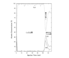
- FIG. 8A is a depth direction analysis of the wiring layer structure by Auger electron spectroscopy analysis
- FIG. 8B is a transmission electron microscope image of the film cross section.
- depth direction analysis revealed that Al and O were concentrated at the boundary between the Cu alloy layer and the oxygen-containing Cu alloy layer (sputtering time was around 50 minutes to around 60 minutes). Part corresponding to). Further, as shown in FIG.
- the concentrated layer of Al and O between the Cu alloy layer and the oxygen-containing Cu alloy layer is The crystal structure was clearly different from that of the oxygen-containing Cu alloy layer, and it was found that the layer was about 4 nm thick. Therefore, it was determined that the heterogeneous layer mainly composed of oxygen and an additive element (in this case, Al) generated between the Cu alloy layer and the oxygen-containing Cu alloy layer is an oxide layer.
- the “oxide layer” described in claim 1 of the present application refers to this heterogeneous layer specified by Auger electron spectroscopy and TEM (transmission electron microscope). Further, when the specific resistance of the Cu alloy layer according to the present invention was measured by a four-point probe test, it was about 5 ⁇ cm.
- Hydrogen plasma treatment The following conditions, Atmosphere: Hydrogen gas Hydrogen gas flow rate: 500 sccm Hydrogen gas pressure 250Pa Processing temperature: 250 ° C Output: 0.1 W / cm 2 Hydrogen plasma treatment was performed at a treatment time of 60 seconds.
- Table 1 is a diagram comparing an example (left side) and a comparative example (right side) according to the present invention.
- Table 1 shows the composition (additive element) and thickness of the oxygen-containing Cu alloy layer and the Cu alloy layer and the thickness of the pure copper layer for each of Examples 1 to 17 and Comparative Examples 1 and 2, and the hydrogen plasma treatment. The result of each cross-cut adhesion test before and after was shown.
- the structure of the glass substrate is the same as described above. That is, the thing of the dimension of length 320mm x width 400mm x thickness 0.7mm which coated the amorphous Si layer was used.
- the substrate heating temperature is 100 ° C.
- the sputtering conditions for the Cu alloy layer are the same as described above, that is, Atmosphere: Ar Atmospheric pressure 0.4Pa
- the substrate heating temperature is 100 ° C., the composition and thickness of each layer are changed.
- the sputtering conditions for the pure copper layer in the next step are the same as the sputtering conditions for the Cu alloy layer, that is, Atmosphere: Ar Atmospheric pressure 0.4Pa
- the substrate heating temperature is 100 ° C.
- a pure copper sputtering target (the inevitable impurities are less than 1 atomic%) is used, and the film thickness is changed.
- the conditions for the hydrogen annealing, the thin film structure evaluation, the conditions for the hydrogen plasma treatment, and the conditions for the cross-cut adhesion test are the same as described above.
- the adhesion to the base substrate is high, and not only the diffusion barrier property to the base substrate is excellent, but also the low resistance wiring layer structure excellent in hydrogen plasma resistance, And a manufacturing method thereof.
- Substrate 2 Cu—O layer (oxygen-containing Cu layer or oxygen-containing Cu alloy layer) 3 Al oxide layer 4 Cu-Al alloy layer 5 Cu conductive layer 11 laminated film 12 wiring layer 13 semiconductor thin film surface 105 transistor 111 transparent substrate 112 gate electrode 114 gate insulating layer 116 silicon layer 118 n-type silicon layer 120a metal Wiring layer 120b Metal wiring layer 122 Resist film 127 Source electrode layer 128 Drain electrode layer 131 Source region 132 Drain region 134 Passivation layer 136 Transparent electrode layer 137 Contact hole 151 Oxygen-containing Cu alloy layer 152 Cu alloy layer
Landscapes
- Chemical & Material Sciences (AREA)
- Engineering & Computer Science (AREA)
- Materials Engineering (AREA)
- Mechanical Engineering (AREA)
- Metallurgy (AREA)
- Organic Chemistry (AREA)
- Thin Film Transistor (AREA)
- Internal Circuitry In Semiconductor Integrated Circuit Devices (AREA)
- Non-Insulated Conductors (AREA)
- Electrodes Of Semiconductors (AREA)
Abstract
Description
本願は、2009年06月12日に日本出願された特願2009-141440に基づいて優先権を主張し、その内容をここに援用する。
上記酸素含有Cu層又は酸素含有Cu合金層に含まれる添加元素は、20原子%以下、望ましくは15原子%以下含まれていてもよい。上記添加元素が20原子%以下であると、酸素含有Cu層又は酸素含有Cu合金層中に生成される酸化物や金属間化合物の量が制限されることから、電気抵抗値が著しく増大することがなく、配線層としての利用に支障を来たすことがない。
上記添加元素は、20原子%以下、望ましくは15原子%以下含まれていてもよい。上記添加元素が20原子%以下であると、酸素含有Cu層又は酸素含有Cu合金層中に生成される酸化物や金属間化合物の量が制限されることから、電気抵抗値が著しく増大することがなく、配線層としての利用に支障を来たすことがない。
まず、下地基板1として半導体基板またはガラス基板を準備し、その表面に銅を含有するターゲットを利用してO2雰囲気内でスパッタを行う。この時使用する銅を含有するターゲットは、Ca、Mg、Li、Al、Zr、Ti、Si、Mn、Cr、希土類からなる群より選択される少なくとも一種類の添加元素を含んでいてもよい。
以下、本発明に基づいて実際に配線層構造を形成し、その評価を行った結果を説明する。
次に、これをスパッタ装置に挿入し、溶解調整したCu-4原子%Alの成分組成を有するCu合金スパッタリングターゲットを用いて、
雰囲気:Ar+酸素(容量%でAr/酸素=90/10)の酸化雰囲気
雰囲気圧力0.4Pa
基板加熱温度100℃の条件でスパッタを行い、膜厚50nmの酸素含有Cu合金層を形成した。
溶解調整したCu-4原子%Alの成分組成を有するCu合金スパッタリングターゲットを用いて、
雰囲気:Ar
雰囲気圧力0.4Pa
基板加熱温度100℃の条件でスパッタを行い、膜厚300nmのCu合金層を形成した。
次に、
雰囲気:H2+N2(容量%でH2/N2=50/50)
雰囲気圧力0.1MPa(1気圧)
温度300℃
保持時間30分の条件で水素アニールを行った。
オージェ電子分光分析により試料の深さ方向分析、および試料断面をTEM(透過電子顕微鏡)により観察した。その結果を図8Aおよび図8Bに示す。図8Aがオージェ電子分光分析による配線層構造の深さ方向分析、図8Bが膜断面の透過型電子顕微鏡像である。図8Aに示したように、深さ方向分析より、AlとOが、Cu合金層と酸素含有Cu合金層の境界に濃縮していることがわかった(スパッタ時間が50分付近~60分付近に対応する部分)。また、図8Bに示したように、膜断面のTEM像(倍率:50万倍以上)より、Cu合金層と酸素含有Cu合金層の間にあるAlとOの濃縮層は、Cu合金層や酸素含有Cu合金層と明らかに結晶構造が異なっており、厚さ約4nmの層であることがわかった。そこで、このCu合金層と酸素含有Cu合金層の間に生成した酸素と添加元素(この場合Al)が主成分となる異相の層が酸化物層であると判断した。本願請求項1に記載の「酸化物層」とは、オージェ電子分光分析及びTEM(透過電子顕微鏡)によって特定された、この異相の層を指している。また、四探針試験により、本発明によるCu合金層の比抵抗を測定したところ約5μΩcmであった。
以下の条件、
雰囲気:水素ガス
水素ガス流量:500sccm
水素ガス圧250Pa
処理温度:250℃
出力:0.1W/cm2
処理時間60秒で水素プラズマ処理を行った。
上記水素プラズマ処理の前後において、以下の碁盤目付着試験を行った。JIS-5400に準じ、上記試料表面にそれぞれ0.5mm、1mm、1.5mmおよび2mmの間隔で縦横にそれぞれ11本の溝を、表面からガラス基板に達する深さで、かつ0.1mmの溝幅で切り込みをカッターで入れ、100個の升目を形成し、この升目全体にわたって3M社製スコッチテープ(登録商標)を密着して貼り付け、次いで一気に引き剥がし、試料表面の100個の升目のうちの剥離した升目の数(個/100)を測定した。その結果、剥離した升目はいずれも0個であった。
雰囲気:Ar+酸素(容量%でAr/酸素=90/10)の酸化雰囲気
雰囲気圧力0.4Pa
基板加熱温度100℃であり、Cu合金層のスパッタ条件も前述同様、すなわち、
雰囲気:Ar
雰囲気圧力0.4Pa
基板加熱温度100℃であるが、それぞれ、各層の組成と膜厚を変化させている。また、次工程の純銅層のスパッタ条件は、Cu合金層のスパッタ条件と同様、すなわち、
雰囲気:Ar
雰囲気圧力0.4Pa
基板加熱温度100℃であるが、純銅スパッタリングターゲット(不可避不純物は1原子%未満)を用いており、膜厚を変化させている。さらに、水素アニールの条件、薄膜構造評価、水素プラズマ処理の条件、碁盤目付着試験の条件は、前述と同様である。

2 Cu-O層(酸素含有Cu層又は酸素含有Cu合金層)
3 Alを含有する酸化物層
4 Cu―Al合金層
5 Cu導電層
11 積層膜
12 配線層
13 半導体薄膜表面
105 トランジスタ
111 透明基板
112 ゲート電極
114 ゲート絶縁層
116 シリコン層
118 n型シリコン層
120a 金属配線層
120b 金属配線層
122 レジスト膜
127 ソース電極層
128 ドレイン電極層
131 ソース領域
132 ドレイン領域
134 パッシベーション層
136 透明電極層
137 コンタクトホール
151 酸素含有Cu合金層
152 Cu合金層
Claims (19)
- 半導体基板又はガラス基板の下地基板と、
該下地基板上に形成された酸素含有Cu層又は酸素含有Cu合金層と、
該酸素含有Cu層又は該酸素含有Cu合金層上に形成された、Al、Zr、Tiのうち少なくとも一種を含有する酸化物層と、
該酸化物層上に形成された、Al、Zr、Tiのうち少なくとも一種を含有するCu合金層と、
を備えた配線層構造。 - 前記酸素含有Cu合金層は、Ca、Mg、Li、Al、Zr、Ti、Si、Mn、Cr、希土類からなる群より選択される少なくとも一種類の添加元素を含む請求項1に記載の配線層構造。
- 前記酸素含有Cu合金層に含まれる添加元素は、20原子%以下である請求項2に記載の配線層構造。
- 前記酸素含有Cu層又は酸素含有Cu合金層に含まれる酸素は、1原子%以上30原子%以下である請求項1から3のいずれか一項に記載の配線層構造。
- 前記Cu合金層は、さらにCa、Mg、Li、Si、Mn、Cr、希土類からなる群より選択される少なくとも一種類の添加元素を含む請求項1に記載の配線層構造。
- 前記Cu合金層に含まれるAl、Zr、Ti合計の添加元素は、1原子%以上15原子%以下である請求項1に記載の配線層構造。
- 前記Cu合金層上に形成されたCu導電層をさらに備えた請求項1に記載の配線層構造。
- 前記Cu導電層が99原子%以上の純銅である請求項7に記載の配線層構造。
- 前記酸素含有Cu層又は酸素含有Cu合金層は10nm~100nmの厚みを有し、前記酸化物層は1nm~20nmの厚みを有し、前記Cu合金層は10nm~100nmの厚みを有し、前記Cu導電層は200nm~10μmの厚みを有する請求項7または8に記載の配線層構造。
- 半導体基板又はガラス基板からなる下地基板上に、少なくともCuを含有するターゲットを利用してO2雰囲気にてスパッタする工程(a)と、
Al、Zr、Tiのうち少なくとも一種を含有するCu合金をターゲットとして不活性ガス雰囲気にてスパッタする工程(b)と、
前記工程(a)及び前記工程(b)によって形成された層にエッチングにより配線層パターンを形成して、前記下地基板の一部を露出させる工程(c)と、
水素プラズマ処理を施して露出した前記下地基板表面に存在するダングリングボンドを終端させる工程(d)と、
をこの順に備え、
前記工程(b)の後で前記工程(d)の前に、水素雰囲気中にてアニールを行う工程(e)を、さらに備える配線層構造の製造方法。 - 前記工程(a)で使用される前記少なくともCuを含有するターゲットは、さらに、Ca、Mg、Li、Al、Zr、Ti、Si、Mn、Cr、希土類からなる群より選択される少なくとも一種類の添加元素を含む請求項10に記載の配線層構造の製造方法。
- 前記工程(a)で使用される前記少なくともCuを含有するターゲットに含まれる添加元素は、20原子%以下である請求項11に記載の配線層構造の製造方法。
- 前記工程(a)のスパッタで使用されるO2雰囲気は、体積分率で1%以上30%以下である請求項10に記載の配線層構造の製造方法。
- 前記Al、Zr、Tiのうち少なくとも一種を含有するCu合金ターゲットは、さらにCa、Mg、Li、Si、Mn、Cr、希土類からなる群より選択される少なくとも一種類の添加元素を含む請求項10に記載の配線層構造の製造方法。
- 前記Al、Zr、Tiのうち少なくとも一種を含有するCu合金ターゲットに含まれるAl、Zr、Tiの添加元素は、1原子%以上15原子%以下である請求項10に記載の配線層構造の製造方法。
- 前記工程(b)の後に、少なくともCuを含有するターゲットを利用して不活性ガス雰囲気にてスパッタする工程(f)を、さらに有する請求項10から15のいずれか一項に記載の配線層構造の製造方法。
- 前記工程(f)で使用される前記少なくともCuを含有するターゲットは、99原子%以上のCuを含有する請求項16に記載の配線層構造の製造方法。
- 半導体基板又はガラス基板の下地基板と、前記下地基板上に形成されたゲート電極と、前記ゲート電極を覆うゲート絶縁層と、前記ゲート絶縁層上に形成された半導体層と、前記半導体層上に形成されたソース領域およびドレイン領域と、前記ソース領域および前記ドレイン領域にそれぞれ接触して形成されたソース電極層およびドレイン電極層と、を有する薄膜トランジスタであって、前記ゲート電極、前記ソース電極層、及び前記ドレイン電極層の少なくとも1つが請求項1に記載の配線層構造から形成されている薄膜トランジスタ。
- 半導体基板又はガラス基板の下地基板上にゲート電極を形成する工程と、前記ゲート電極を覆ってゲート絶縁層を形成する工程と、前記ゲート絶縁層上に半導体層を形成する工程と、前記半導体層上に不純物を高濃度に添加した半導体層を形成する工程と、前記不純物を高濃度に添加した半導体層上に金属配線層を形成する工程と、前記金属配線層、前記不純物を高濃度に添加した半導体層、および前記半導体層をパターンニングする工程とを有し、請求項10から17のいずれか一項に記載の配線層構造の製造方法によって前記金属配線層を製造する薄膜トランジスタの製造方法であって、前記金属配線層を形成する工程は前記工程(a)および(b)であり、前記パターンニングする工程は前記工程(c)である薄膜トランジスタの製造方法。
Priority Applications (3)
| Application Number | Priority Date | Filing Date | Title |
|---|---|---|---|
| KR1020117024816A KR101260612B1 (ko) | 2009-06-12 | 2010-05-11 | 배선층 구조 및 그 제조 방법 |
| CN201080025444.0A CN102804352B (zh) | 2009-06-12 | 2010-05-11 | 布线层结构及其制造方法 |
| US13/265,022 US8624397B2 (en) | 2009-06-12 | 2010-05-11 | Electrode layer structure for a thin-film transistor and process for manufacture thereof |
Applications Claiming Priority (2)
| Application Number | Priority Date | Filing Date | Title |
|---|---|---|---|
| JP2009-141440 | 2009-06-12 | ||
| JP2009141440A JP5548396B2 (ja) | 2009-06-12 | 2009-06-12 | 薄膜トランジスタ用配線層構造及びその製造方法 |
Publications (1)
| Publication Number | Publication Date |
|---|---|
| WO2010143355A1 true WO2010143355A1 (ja) | 2010-12-16 |
Family
ID=43308618
Family Applications (1)
| Application Number | Title | Priority Date | Filing Date |
|---|---|---|---|
| PCT/JP2010/003187 Ceased WO2010143355A1 (ja) | 2009-06-12 | 2010-05-11 | 配線層構造及びその製造方法 |
Country Status (6)
| Country | Link |
|---|---|
| US (1) | US8624397B2 (ja) |
| JP (1) | JP5548396B2 (ja) |
| KR (1) | KR101260612B1 (ja) |
| CN (1) | CN102804352B (ja) |
| TW (1) | TWI497598B (ja) |
| WO (1) | WO2010143355A1 (ja) |
Families Citing this family (12)
| Publication number | Priority date | Publication date | Assignee | Title |
|---|---|---|---|---|
| KR20160013048A (ko) | 2013-05-29 | 2016-02-03 | 다츠다 덴센 가부시키가이샤 | 전자파 실드 필름, 이것을 사용한 프린트 배선판, 및 압연 동박 |
| JP5735093B1 (ja) * | 2013-12-24 | 2015-06-17 | 株式会社マテリアル・コンセプト | 太陽電池及びその製造方法 |
| JP6310816B2 (ja) * | 2014-08-26 | 2018-04-11 | ルネサスエレクトロニクス株式会社 | 半導体装置の製造方法 |
| JP6228631B1 (ja) * | 2016-06-07 | 2017-11-08 | 株式会社コベルコ科研 | Al合金スパッタリングターゲット |
| CN109143745B (zh) * | 2017-06-27 | 2021-02-26 | 深圳光峰科技股份有限公司 | 发光聚集器、发光设备及投影光源 |
| US10760156B2 (en) | 2017-10-13 | 2020-09-01 | Honeywell International Inc. | Copper manganese sputtering target |
| KR102462381B1 (ko) * | 2017-12-19 | 2022-11-01 | 삼성전자주식회사 | 반도체 장치의 제조 방법 |
| US11035036B2 (en) | 2018-02-01 | 2021-06-15 | Honeywell International Inc. | Method of forming copper alloy sputtering targets with refined shape and microstructure |
| CN112055888A (zh) * | 2019-04-09 | 2020-12-08 | 株式会社爱发科 | Cu合金靶材、配线膜、半导体装置、液晶显示装置 |
| JP6768180B1 (ja) * | 2019-04-09 | 2020-10-14 | 株式会社アルバック | Cu合金ターゲット、配線膜、半導体装置、液晶表示装置 |
| CN111876629B (zh) * | 2020-08-04 | 2021-03-23 | 天水华洋电子科技股份有限公司 | 一种引线框架用高性能铜基合金材料及其制备方法 |
| CN118326201B (zh) * | 2024-06-17 | 2024-09-17 | 上海理工大学 | 铜基合金接触线及其连续生产方法 |
Citations (6)
| Publication number | Priority date | Publication date | Assignee | Title |
|---|---|---|---|---|
| JPH03166731A (ja) * | 1989-11-27 | 1991-07-18 | Hitachi Ltd | 銅又は銅合金の配線方法及び構造 |
| JPH06177128A (ja) * | 1992-12-07 | 1994-06-24 | Japan Energy Corp | 半導体装置とその製造方法 |
| JPH06333925A (ja) * | 1993-05-20 | 1994-12-02 | Nippon Steel Corp | 半導体集積回路及びその製造方法 |
| JPH1154458A (ja) * | 1997-05-08 | 1999-02-26 | Applied Materials Inc | メタライゼーション構造体 |
| JP2007027259A (ja) * | 2005-07-13 | 2007-02-01 | Fujitsu Ltd | 半導体装置の製造方法及び半導体装置 |
| JP2009010089A (ja) * | 2007-06-27 | 2009-01-15 | Mitsubishi Materials Corp | 密着性に優れた配線下地膜およびこの配線下地膜を含む密着性に優れた二重構造配線膜 |
Family Cites Families (7)
| Publication number | Priority date | Publication date | Assignee | Title |
|---|---|---|---|---|
| JP4554011B2 (ja) * | 1999-08-10 | 2010-09-29 | ルネサスエレクトロニクス株式会社 | 半導体集積回路装置の製造方法 |
| JP2007180407A (ja) * | 2005-12-28 | 2007-07-12 | Matsushita Electric Ind Co Ltd | 半導体装置およびその製造方法 |
| TW200827463A (en) | 2006-10-12 | 2008-07-01 | Ulvac Inc | Conductive film forming method, thin film transistor, panel with thin film transistor and thin film transistor manufacturing method |
| WO2008081805A1 (ja) | 2006-12-28 | 2008-07-10 | Ulvac, Inc. | 配線膜の形成方法、トランジスタ、及び電子装置 |
| JP5017282B2 (ja) | 2006-12-28 | 2012-09-05 | 株式会社アルバック | 配線膜の形成方法 |
| KR101102891B1 (ko) * | 2007-09-04 | 2012-01-10 | 삼성전자주식회사 | 배선구조 및 이를 이용한 박막 트랜지스터 |
| CN101971350B (zh) * | 2008-04-15 | 2012-10-10 | 株式会社爱发科 | 薄膜晶体管、薄膜晶体管的制造方法 |
-
2009
- 2009-06-12 JP JP2009141440A patent/JP5548396B2/ja not_active Expired - Fee Related
-
2010
- 2010-05-10 TW TW099114804A patent/TWI497598B/zh active
- 2010-05-11 WO PCT/JP2010/003187 patent/WO2010143355A1/ja not_active Ceased
- 2010-05-11 CN CN201080025444.0A patent/CN102804352B/zh active Active
- 2010-05-11 US US13/265,022 patent/US8624397B2/en not_active Expired - Fee Related
- 2010-05-11 KR KR1020117024816A patent/KR101260612B1/ko active Active
Patent Citations (6)
| Publication number | Priority date | Publication date | Assignee | Title |
|---|---|---|---|---|
| JPH03166731A (ja) * | 1989-11-27 | 1991-07-18 | Hitachi Ltd | 銅又は銅合金の配線方法及び構造 |
| JPH06177128A (ja) * | 1992-12-07 | 1994-06-24 | Japan Energy Corp | 半導体装置とその製造方法 |
| JPH06333925A (ja) * | 1993-05-20 | 1994-12-02 | Nippon Steel Corp | 半導体集積回路及びその製造方法 |
| JPH1154458A (ja) * | 1997-05-08 | 1999-02-26 | Applied Materials Inc | メタライゼーション構造体 |
| JP2007027259A (ja) * | 2005-07-13 | 2007-02-01 | Fujitsu Ltd | 半導体装置の製造方法及び半導体装置 |
| JP2009010089A (ja) * | 2007-06-27 | 2009-01-15 | Mitsubishi Materials Corp | 密着性に優れた配線下地膜およびこの配線下地膜を含む密着性に優れた二重構造配線膜 |
Also Published As
| Publication number | Publication date |
|---|---|
| TWI497598B (zh) | 2015-08-21 |
| US8624397B2 (en) | 2014-01-07 |
| JP5548396B2 (ja) | 2014-07-16 |
| KR20120022798A (ko) | 2012-03-12 |
| CN102804352B (zh) | 2015-11-25 |
| CN102804352A (zh) | 2012-11-28 |
| JP2010287791A (ja) | 2010-12-24 |
| TW201112331A (en) | 2011-04-01 |
| US20120068265A1 (en) | 2012-03-22 |
| KR101260612B1 (ko) | 2013-05-03 |
Similar Documents
| Publication | Publication Date | Title |
|---|---|---|
| JP5548396B2 (ja) | 薄膜トランジスタ用配線層構造及びその製造方法 | |
| US9024322B2 (en) | Wiring structure and display device | |
| US8558382B2 (en) | Interconnection structure and display device including interconnection structure | |
| JP4567091B1 (ja) | 表示装置用Cu合金膜および表示装置 | |
| JP5017282B2 (ja) | 配線膜の形成方法 | |
| CN103003860B (zh) | 显示装置用Cu合金膜和显示装置 | |
| TW201234433A (en) | Wiring structure | |
| JP2011091364A (ja) | 配線構造およびその製造方法、並びに配線構造を備えた表示装置 | |
| JP5354781B2 (ja) | バリア層を構成層とする薄膜トランジスターおよび前記バリア層のスパッタ成膜に用いられるCu合金スパッタリングターゲット | |
| TW201030979A (en) | Thin-film transistor having superior adhesive strength between barrier films and drain/source electrode films | |
| US20190148412A1 (en) | Multilayer wiring film and thin film transistor element | |
| JP5429718B2 (ja) | 酸化物半導体用電極、その形成方法 | |
| CN103258725B (zh) | 薄膜配线形成方法及薄膜配线 | |
| WO2011125802A1 (ja) | 配線構造、表示装置、および半導体装置 | |
| JP5008146B2 (ja) | 密着性に優れた銅合金複合膜 |
Legal Events
| Date | Code | Title | Description |
|---|---|---|---|
| WWE | Wipo information: entry into national phase |
Ref document number: 201080025444.0 Country of ref document: CN |
|
| 121 | Ep: the epo has been informed by wipo that ep was designated in this application |
Ref document number: 10785887 Country of ref document: EP Kind code of ref document: A1 |
|
| WWE | Wipo information: entry into national phase |
Ref document number: 13265022 Country of ref document: US |
|
| ENP | Entry into the national phase |
Ref document number: 20117024816 Country of ref document: KR Kind code of ref document: A |
|
| NENP | Non-entry into the national phase |
Ref country code: DE |
|
| 122 | Ep: pct application non-entry in european phase |
Ref document number: 10785887 Country of ref document: EP Kind code of ref document: A1 |