WO2010143387A1 - 超音波探触子 - Google Patents
超音波探触子 Download PDFInfo
- Publication number
- WO2010143387A1 WO2010143387A1 PCT/JP2010/003746 JP2010003746W WO2010143387A1 WO 2010143387 A1 WO2010143387 A1 WO 2010143387A1 JP 2010003746 W JP2010003746 W JP 2010003746W WO 2010143387 A1 WO2010143387 A1 WO 2010143387A1
- Authority
- WO
- WIPO (PCT)
- Prior art keywords
- ultrasonic probe
- backing layer
- ultrasonic
- backing member
- acoustic
- Prior art date
- Legal status (The legal status is an assumption and is not a legal conclusion. Google has not performed a legal analysis and makes no representation as to the accuracy of the status listed.)
- Ceased
Links
Images


Classifications
-
- B—PERFORMING OPERATIONS; TRANSPORTING
- B06—GENERATING OR TRANSMITTING MECHANICAL VIBRATIONS IN GENERAL
- B06B—METHODS OR APPARATUS FOR GENERATING OR TRANSMITTING MECHANICAL VIBRATIONS OF INFRASONIC, SONIC, OR ULTRASONIC FREQUENCY, e.g. FOR PERFORMING MECHANICAL WORK IN GENERAL
- B06B1/00—Methods or apparatus for generating mechanical vibrations of infrasonic, sonic, or ultrasonic frequency
- B06B1/02—Methods or apparatus for generating mechanical vibrations of infrasonic, sonic, or ultrasonic frequency making use of electrical energy
- B06B1/06—Methods or apparatus for generating mechanical vibrations of infrasonic, sonic, or ultrasonic frequency making use of electrical energy operating with piezoelectric effect or with electrostriction
- B06B1/0644—Methods or apparatus for generating mechanical vibrations of infrasonic, sonic, or ultrasonic frequency making use of electrical energy operating with piezoelectric effect or with electrostriction using a single piezoelectric element
- B06B1/0662—Methods or apparatus for generating mechanical vibrations of infrasonic, sonic, or ultrasonic frequency making use of electrical energy operating with piezoelectric effect or with electrostriction using a single piezoelectric element with an electrode on the sensitive surface
- B06B1/0677—Methods or apparatus for generating mechanical vibrations of infrasonic, sonic, or ultrasonic frequency making use of electrical energy operating with piezoelectric effect or with electrostriction using a single piezoelectric element with an electrode on the sensitive surface and a high impedance backing
-
- A—HUMAN NECESSITIES
- A61—MEDICAL OR VETERINARY SCIENCE; HYGIENE
- A61B—DIAGNOSIS; SURGERY; IDENTIFICATION
- A61B8/00—Diagnosis using ultrasonic, sonic or infrasonic waves
-
- G—PHYSICS
- G01—MEASURING; TESTING
- G01N—INVESTIGATING OR ANALYSING MATERIALS BY DETERMINING THEIR CHEMICAL OR PHYSICAL PROPERTIES
- G01N29/00—Investigating or analysing materials by the use of ultrasonic, sonic or infrasonic waves; Visualisation of the interior of objects by transmitting ultrasonic or sonic waves through the object
- G01N29/04—Analysing solids
- G01N29/06—Visualisation of the interior, e.g. acoustic microscopy
- G01N29/0654—Imaging
- G01N29/0672—Imaging by acoustic tomography
-
- G—PHYSICS
- G10—MUSICAL INSTRUMENTS; ACOUSTICS
- G10K—SOUND-PRODUCING DEVICES; METHODS OR DEVICES FOR PROTECTING AGAINST, OR FOR DAMPING, NOISE OR OTHER ACOUSTIC WAVES IN GENERAL; ACOUSTICS NOT OTHERWISE PROVIDED FOR
- G10K11/00—Methods or devices for transmitting, conducting or directing sound in general; Methods or devices for protecting against, or for damping, noise or other acoustic waves in general
- G10K11/002—Devices for damping, suppressing, obstructing or conducting sound in acoustic devices
-
- A—HUMAN NECESSITIES
- A61—MEDICAL OR VETERINARY SCIENCE; HYGIENE
- A61B—DIAGNOSIS; SURGERY; IDENTIFICATION
- A61B8/00—Diagnosis using ultrasonic, sonic or infrasonic waves
- A61B8/44—Constructional features of the ultrasonic, sonic or infrasonic diagnostic device
- A61B8/4405—Device being mounted on a trolley
-
- A—HUMAN NECESSITIES
- A61—MEDICAL OR VETERINARY SCIENCE; HYGIENE
- A61B—DIAGNOSIS; SURGERY; IDENTIFICATION
- A61B8/00—Diagnosis using ultrasonic, sonic or infrasonic waves
- A61B8/44—Constructional features of the ultrasonic, sonic or infrasonic diagnostic device
- A61B8/4444—Constructional features of the ultrasonic, sonic or infrasonic diagnostic device related to the probe
- A61B8/4455—Features of the external shape of the probe, e.g. ergonomic aspects
Definitions
- the present invention relates to an ultrasonic probe used for ultrasonic diagnosis.
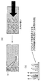
- FIG. 1 is a diagram showing an example of the external appearance of an ultrasonic probe and an ultrasonic diagnostic apparatus.
- the ultrasonic probe is connected to the ultrasonic diagnostic apparatus with a cable, transmits ultrasonic waves in the direction of the arrow in the figure, and is in the direction opposite to the arrow reflected by the living body. Receive the reflected wave.
- the ultrasonic diagnostic apparatus performs image analysis on the reflected wave received by the ultrasonic probe, and displays an internal image obtained by the analysis on the monitor.
- ultrasonic waves when transmitting ultrasonic waves from a piezoelectric vibrator, ultrasonic waves are radiated not only on the front face of the vibrator but also on the rear face.
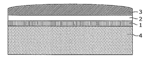
- FIG. 2 is a longitudinal sectional view showing a configuration of a conventional ultrasonic probe. From the upper side of FIG. 2, the acoustic lens 3, the matching layer 2, the piezoelectric vibrator 1, and the backing layer 4 are stacked.
- ultrasonic waves transmitted from the piezoelectric vibrator 1 pass through the matching layer 2 and the acoustic lens 3 and are radiated to the living body.
- the ultrasonic wave reflected in the living body follows the route opposite to the forward path, and is received again by the piezoelectric vibrator 1, and a signal corresponding to the reception intensity and response time becomes shaded and visualized.
- ultrasonic waves having a phase opposite to that of the front surface are simultaneously emitted from the piezoelectric vibrator 1 to the back surface.
- the ultrasonic wave radiated to the back surface of the piezoelectric vibrator 1 is attenuated by the backing layer 4.
- the backing layer 4 is made of a material that does not have a loss sufficient to attenuate the ultrasonic waves radiated to the back surface
- the ultrasonic waves having the opposite phase are reflected in the backing layer 4 to cause piezoelectric vibration. May return to child 1 side.
- the ultrasonic resolution of the ultrasonic diagnostic apparatus is maintained by arranging a material having an internal loss and a distance sufficient to obtain sufficient attenuation for the ultrasonic wave output on the back surface in the backing layer 4. .
- this conventional method has a drawback that the backing layer itself becomes thick.
- a heat dissipation block is disposed on the back surface of the backing layer 4 to attenuate the ultrasonic waves output to the back surface of the piezoelectric vibrator 1.
- the conventional configuration has a problem that the thickness of the backing layer 4 is inevitably increased. Further, even if a heat dissipation block is provided on the back surface of the backing layer 4 in order to reduce the thickness of the backing layer 4, a heat dissipation block is required in addition to the backing layer 4, so that the entire configuration for attenuating the ultrasonic waves It is difficult to reduce the thickness. Furthermore, since a member different from the backing layer is required when using the heat dissipation block, there arises a problem that the cost for manufacturing the ultrasonic probe increases.
- the present invention solves the above-mentioned conventional problems, effectively attenuates the ultrasonic wave radiated from the piezoelectric vibrator to the back surface by the backing layer, and reduces the reflected wave returning from the back surface to the vibrator side,
- the object is to significantly reduce the thickness of the backing layer as compared with the prior art.
- an ultrasonic probe according to the present invention is bonded to a vibration element that emits ultrasonic waves and a back surface of the vibration element, and has a phase opposite to the front direction of the vibration element.
- a backing member for attenuating the ultrasonic waves radiated in the back direction of the vibration element, and the backing member includes a plurality of acoustic tubes having different lengths based on the principle of superposition of acoustic waves.
- the longitudinal direction is arranged in a direction that coincides with the traveling direction of the ultrasonic wave emitted from the vibration element in the front direction and the back direction, and the acoustic tube is configured to emit the ultrasonic wave radiated by the vibration element to the backing member side. Attenuate in whole or in part.
- the backing layer provided on the back surface of the piezoelectric vibrator has an acoustic wave having a sufficiently short width (at least half a wavelength or less) with respect to the wavelength of the emitted ultrasonic wave.
- One or more tubes are provided. The length of the acoustic tube is set according to the wavelength of the emitted ultrasonic wave so that the incident wave and the reflected wave cancel each other out.
- the reflected wave is effectively reduced by canceling the reflected wave reflected and returned at the end of the backing layer, and a good ultrasonic image without noise is obtained. be able to.
- the backing layer can be structurally thinned, the cost associated with the material can be reduced and the device can be made thinner. Furthermore, since heat generation can be suppressed, a stronger output is possible, and the apparent sensitivity is improved accordingly.
- FIG. 1A and FIG. 1B are diagrams showing an example of the appearance of an ultrasonic probe and an ultrasonic diagnostic apparatus.
- FIG. 2 is a cross-sectional view of a conventional ultrasonic probe.
- FIG. 3 is a cross-sectional view of an ultrasonic probe including a backing layer having a single acoustic tube in the first embodiment of the present invention.
- FIG. 4 is a cross-sectional view of an ultrasonic probe including a backing layer having a plurality of acoustic tubes according to Embodiment 2 of the present invention.
- FIG. 5 is a cross-sectional view showing an example of a backing layer including acoustic tubes arranged based on the quadratic residue series according to Embodiment 2 of the present invention.
- FIG. 1A and FIG. 1B are diagrams showing an example of the appearance of an ultrasonic probe and an ultrasonic diagnostic apparatus.
- FIG. 2 is a cross-sectional view of a conventional ultrasonic probe.
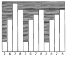
- FIG. 6 is a cross-sectional view showing an example of a backing layer including acoustic tubes arranged based on the primitive root series in the second embodiment of the present invention.
- FIG. 7 is a diagram comparing noise amplitude changes with and without the acoustic tube in the backing layer.
- FIGS. 8A to 8D are a perspective view and a three-dimensional view showing a three-dimensional structure of a one-dimensional acoustic tube.
- FIGS. 9A to 9D are a perspective view and a three-dimensional view showing a three-dimensional structure of a two-dimensional acoustic tube.
- FIGS. 10A and 10B are cross-sectional views showing the bonding direction of the acoustic tube formed in the backing layer and the other layer having the opening.
- FIG. 11 is a diagram showing the relationship between the dicing direction of the piezoelectric vibrator and the forming direction of the one-dimensional acoustic tube formed in the backing layer.
- 12 (a) and 12 (b) are diagrams showing a method for forming a backing layer when microcapsules are used as acoustic tubes.
- FIG. 13 is a diagram showing a method for forming a backing layer when a spherical microballoon is used.
- FIG. 14A is a flowchart showing a procedure for forming a backing layer using screen printing.
- FIG. 14B is a flowchart showing a forming procedure in a case where a backing layer is formed by embossing using a precision die used in the nanoimprint technology or the like.
- FIG. 14C is a flowchart showing a forming procedure in the case of forming a backing layer using a cylindrical microcapsule as an acoustic tube.
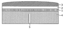
- FIG. 3 is a cross-sectional view showing the ultrasonic probe according to Embodiment 1 of the present invention.
- the ultrasonic probe according to the first embodiment includes a piezoelectric vibrator 1, a matching layer 2, an acoustic lens 3, and a backing layer 4.
- the acoustic tube 5 is arranged inside the backing layer 4 as shown in FIG.
- the acoustic tube 5 has a width that is sufficiently smaller than the wavelength of the ultrasonic wave radiated from the piezoelectric vibrator 1 and is formed to a length that causes cancellation of the ultrasonic wave between the direct wave and the reflected wave.
- the wavelength ⁇ in the backing layer 4 can be obtained by Equation 1.
- the width w of the acoustic tube 5 needs to be w ⁇ Ln in order to maintain the straightness of the sound wave.
- the ultrasonic wave radiated from the piezoelectric vibrator 1 to the back surface can be attenuated and only the front surface ultrasonic wave can be received, the sensitivity of the ultrasonic signal is improved and good. Can be obtained.
- FIG. 4 is a cross-sectional view of the backing layer 4 in the second embodiment of the present invention.
- a plurality of acoustic tubes 5 are arranged inside the backing layer 4.
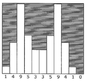
- FIG. 5 is a cross-sectional view showing an example of the arrangement of the acoustic tubes 5 in the second embodiment.
- an example of the backing layer in which the acoustic tubes 5 are arranged based on the quadratic residue series is shown.
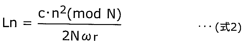
- the length Ln of each acoustic tube is determined by a one-dimensional quadratic residue sequence shown in the following Equation 2.
- c is the speed of sound
- N is a prime number
- n is an integer varying from 0 to (N ⁇ 1)
- ⁇ r is an arbitrary design frequency.
- the length of each acoustic tube 5 is 1 and 4 respectively, with 45.5 ⁇ m as the unit length “1”. , 9, 5, 3, 3, 5, 9, 4, 1, 0.
- FIG. 7 is a diagram comparing noise amplitude changes with and without the acoustic tube in the backing layer.
- the backing layer in which the acoustic tubes 5 are arranged based on the primitive root series is shown. Note that the arrangement of the acoustic tubes 5 shown in FIGS. 5 and 6 is not limited to a one-dimensional arrangement, and may be a two-dimensional arrangement.
- FIG. 8 is a perspective view and a three-side view showing a three-dimensional structure of a one-dimensional acoustic tube.
- FIG. 8A is a perspective view showing the backing layer 4 in which the one-dimensional acoustic tube 5 is formed in the arrangement shown in FIG.
- FIG. 8B grooves that are parallel to the lateral direction are formed in the backing layer 4.
- the depth of the grooves is formed in the order of the depths of 1, 4, 9, 5, 3, 3, 5, 9, 4, 1, 0 in the vertical direction.
- each single groove is a groove having a uniform depth. If this is cut along a plane perpendicular to the longitudinal direction of the grooves, the depths of the respective grooves are arranged in a quadratic residue series as shown in FIG.
- FIG. 9 is a perspective view and a three-dimensional view showing a three-dimensional structure of a two-dimensional acoustic tube.
- FIG. 9A is a perspective view showing the backing layer 4 on which the two-dimensional acoustic tube 5 is formed.
- the grooves are arranged so that the depths of the grooves are repeated in a predetermined pattern when viewed from the vertical direction of the cross section and from the horizontal direction.
- FIG. 10 is a cross-sectional view showing the bonding direction between the surface having the opening of the acoustic tube formed in the backing layer and the piezoelectric vibrator 1.
- FIG. 10A shows an example in which the surface of the backing layer 4 without the opening of the acoustic tube 5 is bonded to the layer of the piezoelectric vibrator 1.
- FIG. 10B shows an example in which the surface of the backing layer 4 having the opening of the acoustic tube 5 is bonded to the layer of the piezoelectric vibrator 1.
- the surface having the opening of the acoustic tube 5 may be on either side with respect to the piezoelectric vibrator 1. It may be formed as shown in FIG. 10A or may be formed as shown in FIG.
- FIG. 11 is a diagram showing the relationship between the dicing direction of the piezoelectric vibrator and the forming direction of the one-dimensional acoustic tube formed in the backing layer.
- the acoustic tube 5 is formed so that the dicing direction of the piezoelectric vibrator 1 and the longitudinal direction of the groove of the acoustic tube 5 are orthogonal to each other.
- a larger number of acoustic tubes with different lengths act on the piezoelectric vibrators for one channel, so that the reflected wave can be more effectively reduced in the backing layer 4.
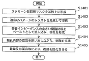
- FIG. 14A is a flowchart showing a procedure for forming a backing layer using screen printing. Specifically, first, a screen printing mask adjusted to obtain a dry thickness of 250 ⁇ m is formed on the substrate (S1401). Next, a resist for printing a predetermined pattern is formed (S1402), and a material with high impedance such as a conductive paste using metal is poured as a paste to perform printing (S1403). Thereby, pores are formed on the substrate.
- the substrate portion that is the substrate to be printed is preferably a material having an acoustic impedance equivalent to or close to that of the conductive paste used for printing.
- a resin material having a small acoustic impedance is poured into the pores, and the interior is filled with resin while completely expelling the air inside the pores using a squeegee (a spatula) or the like (S1404).
- This backing material can be dried or solidified by reaction to obtain a backing member that effectively reduces reflected waves at 5 MHz (S1405).
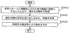
- FIG. 14B is a flowchart showing a forming procedure in a case where a backing layer is formed by embossing using a precision die used in the nanoimprint technology or the like. Specifically, first, a mold finely processed into a predetermined pattern is pressed into a resin to form grooves or pores on the substrate (S1411).
- the aperture is not necessarily 250 ⁇ m or less.
- the wave guide path through which the sound wave is transmitted must be formed by a convex portion.
- a paste having a high acoustic impedance such as metal is filled into the groove or pore obtained here while completely expelling air inside the pore with a squeegee or the like (S1412).
- This backing material can be dried or solidified by reaction to obtain a backing member that effectively reduces reflected waves at 5 MHz (S1413).
- FIG. 12 is a diagram showing a method for forming a backing layer when microcapsules are used as acoustic tubes.
- FIG. 12A is a view showing a method for extruding a resin in which cylindrical microcapsules are mixed.
- FIG. 12B is a diagram showing a method for growing columnar crystals on a substrate by CVD.
- FIG. 14C is a flowchart showing a forming procedure in the case of forming a backing layer using a cylindrical microcapsule as an acoustic tube.
- CVD Chemical Vapor Deposition
- the microballoon may be formed using the carbon fiber or the carbon nanotube whose length is controlled as described above as a nucleus.
- a unit length “1” is set to 45.5 ⁇ m, and it is grown or cut so as to be a maximum of 9 times the length.
- Columnar porous material produced by hydrolyzing and polycondensation reaction (sol-gel reaction) of metal alkoxides containing Si, etc. in a water / oil-based solution using a single fiber or fibrillar material produced as a core A cylindrical microcapsule obtained by baking is formed (S1421). The formed microcapsules are added to the resin at a predetermined blending ratio and extruded (S1422). A member obtained by cutting the extruded resin perpendicularly to the extrusion direction is used as a backing (S1423).
- the cylindrical microcapsules act to align the resin in the longitudinal direction in the resin flow direction. Accordingly, as shown in the left diagram of FIG. 12A, by cutting a resin substrate that has been extruded so that the cut surface is perpendicular to the flow direction, acoustic tubes of different depths can be formed while aligning the apertures. It can be expressed on the surface part. Further, instead of microcapsules, a columnar crystal is grown on a substrate, and a space between the obtained columnar crystals is filled with a resin to form a reflective layer, whereby a backing layer in which the columnar crystal portion is an acoustic tube 5 is formed. 4 can be formed. Since the length of the columnar crystal can be controlled by growing the columnar crystal by CVC or the like, the acoustic tubes 5 arranged based on Embodiment 2 can be formed with high accuracy.
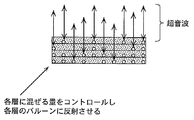
- FIG. 13 is a diagram showing a method for forming the backing layer 4 when a spherical microballoon is used. First, a plurality of types of resin layers are formed using a resin in which spherical microballoons are uniformly mixed at different predetermined ratios.
- the resin layers having different mixing densities formed in this way are stacked in a predetermined order, and are arranged so that the microballoons continue to the length of the acoustic tube 5 in the stacking direction.
- a backing layer 4 in which resin layers are laminated as shown in FIG. 13 can be formed.
- each acoustic tube has been described as a typical example.
- the cross-section of each acoustic tube has any shape such as an ellipse, a triangle, and a hexagon. May be.
- the reflected wave at the backing layer 4 can be attenuated, and the sensitivity of the ultrasonic probe can be increased. Moreover, since heat can be released to the outside using a plurality of acoustic tubes, the heat inside the backing layer 4 can be dissipated.
- the present invention can be used as an ultrasonic probe to reduce the reflected wave at the backing layer and improve the sensitivity of the received ultrasonic signal, and to reduce the thickness and reduce the cost associated with the reduction in thickness. It is.
Landscapes
- Health & Medical Sciences (AREA)
- Life Sciences & Earth Sciences (AREA)
- Physics & Mathematics (AREA)
- Engineering & Computer Science (AREA)
- General Health & Medical Sciences (AREA)
- Pathology (AREA)
- Acoustics & Sound (AREA)
- Public Health (AREA)
- Multimedia (AREA)
- Heart & Thoracic Surgery (AREA)
- Medical Informatics (AREA)
- Molecular Biology (AREA)
- Surgery (AREA)
- Animal Behavior & Ethology (AREA)
- Biophysics (AREA)
- Nuclear Medicine, Radiotherapy & Molecular Imaging (AREA)
- Veterinary Medicine (AREA)
- Radiology & Medical Imaging (AREA)
- Biomedical Technology (AREA)
- Immunology (AREA)
- Chemical & Material Sciences (AREA)
- Analytical Chemistry (AREA)
- Biochemistry (AREA)
- General Physics & Mathematics (AREA)
- Mechanical Engineering (AREA)
- Transducers For Ultrasonic Waves (AREA)
- Ultra Sonic Daignosis Equipment (AREA)
- Investigating Or Analyzing Materials By The Use Of Ultrasonic Waves (AREA)
Abstract
Description
図3は、本発明の実施の形態1における超音波探触子を示す断面図である。図3に示すように、本実施の形態1にかかる超音波探触子は、圧電振動子1、整合層2、音響レンズ3、およびバッキング層4を備えている。

図4は、本発明の実施の形態2におけるバッキング層4の断面図である。バッキング層4の内部には、複数の音響管5が配置されている。
本実施の形態3にかかるバッキング層4を実現する為に、実施の形態1に基づき、基板上に250μmの起伏を精密印刷によって形成する。これにおいて、音響管の長手方向は、印刷されるインクの厚み方向に相当する。図14Aは、スクリーン印刷を利用したバッキング層の形成手順を示すフローチャートである。具体的には、まず、250μmの乾燥厚みが得られるように調整されたスクリーン印刷用マスクを基板上に形成する(S1401)。次に、所定のパターンを印刷するためのレジストを形成し(S1402)、金属を用いた導電ペーストなどのインピーダンスの高い材料をペーストとして流し込み、印刷を行う(S1403)。これにより、基板上に細孔を形成する。なお、ここでは、印刷されるペーストの厚みは、250μm以下を保つようにすることが必要であり、前記条件により音波の細孔への直進性が良好となり、高い効果が得られる。ただし、250μmを超えた時点で効果が急にゼロになるわけではないため、所望の効果が得られていれば、必ずしも全てが250μm以下という精度を保っている必要はない。
本実施の形態4にかかるバッキング層4を実現する為の別の手段は、ナノインプリント技術などに用いられる精密型を用いて、所定のパターンに微細加工された型を樹脂に型押しする技術である。これにより、口径が250μm以下となるような溝または細孔を基板上に形成させることで、実施の形態4のバッキング層4が得られる。図14Bは、ナノインプリント技術などに用いられる精密型を用いた型押しによりバッキング層を形成する場合の形成手順を示すフローチャートである。具体的には、まず、所定のパターンに微細加工された型を樹脂に型押しし、基板上に溝又は細孔を形成する(S1411)。
図12は、音響管としてマイクロカプセルを用いる場合のバッキング層の形成方法を示す図である。図12(a)は、円筒形のマイクロカプセルを混合した樹脂を押し出し成型する方法を示す図である。図12(b)は、CVDにより基板上に柱状結晶を成長させる方法を示す図である。図14Cは、円筒型のマイクロカプセルを音響管として用いたバッキング層を形成する場合の形成手順を示すフローチャートである。ここでは、CVD(Chemical Vapor Deposition)法、またはカーボンナノチューブなどを用いて、柱状結晶の長さをコントロールしながら、結晶を成長させるものとする。あるいは、このように長さをコントロールしたカーボン繊維またはカーボンナノチューブを核として、マイクロバルーンを形成するとしてもよい。
2 整合層
3 音響レンズ
4 バッキング層
5 音響管
Claims (13)
- 超音波を発する振動素子と、
前記振動素子の背面に接合され、前記振動素子の前面方向とは逆の位相で前記振動素子の背面方向に放射された超音波を減衰するバッキング部材とを備え、
前記バッキング部材には、音波の重ね合わせの原理に基づく長さの異なる複数の音響管が、各前記音響管の長手方向が、前記振動素子から発せられる超音波の前面方向および背面方向への進行方向と一致する向きに配置され、
前記音響管は、前記振動素子が前記バッキング部材側に放射した超音波を、全体的にまたは部分的に減衰する
超音波探触子。 - 前記バッキング部材は、前記音響管に代えて、前記音響管に準ずる反射構造体を備える
請求項1に記載の超音波探触子。 - 前記音響管は、前記バッキング部材と他層との接合面上の直線方向に、整数nの順に並ぶよう配列され、
音速をc、素数をN、0~(N-1)まで変化する整数をn、任意の設計周波数をωrとして、各音響管の長さLnが、

請求項1に記載の超音波探触子。 - 前記音響管は、前記バッキング部材と他層との接合面上の直線方向に、整数nの順に並ぶよう配列され、
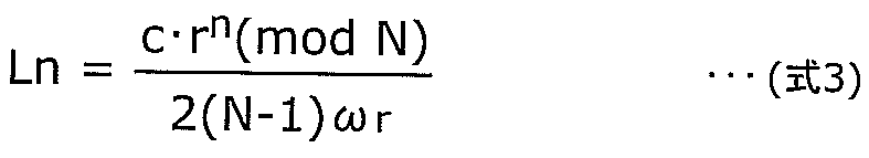
音速をc、素数をN、0~(N-1)まで変化する整数をn、Nの原始根をr、任意の設計周波数をωrとして、各音響管の長さLnが、
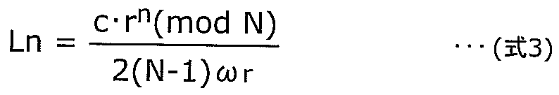
請求項1に記載の超音波探触子。 - 前記バッキング部材は、
複数のマイクロカプセルと、硬化性の高分子樹脂とから構成され、
前記音響管に準ずる反射構造体は、前記高分子樹脂中に分布した前記複数のマイクロカプセルで構成される
請求項1に記載の超音波探触子。 - 前記マイクロカプセルは、所定の長さを有する単繊維のファイバを基材とし、ゾルーゲル反応によって外骨格を付与した球形もしくは、円筒形の素材である
請求項5に記載の超音波探触子。 - 前記マイクロカプセルは、円筒形の素材であり、
前記音響管に準ずる反射構造体は、前記マイクロカプセルが円筒形の長手方向を一方向に揃えて配置されている
請求項5または請求項6に記載の超音波探触子。 - 請求項1に記載の超音波探触子を備える超音波診断装置。
- 超音波探触子に用いるバッキング部材の生成方法であって、
複数のマイクロカプセルと硬化性の高分子樹脂との混和物を、前記マイクロカプセルの添加率を変えて複数生成し、
添加率の異なる複数の前記混和物からなる樹脂層を積層した後、所定の形に硬化成型することにより前記バッキング部材を生成する
生成方法。 - 前記マイクロカプセルを、所定の長さを有する単繊維のファイバを基材とし、ゾル-ゲル反応により外骨格を付与した球形、もしくは、円筒形の素材として生成する
請求項9に記載の生成方法。 - 超音波探触子に用いるバッキング部材の生成方法であって、
複数のマイクロカプセルと硬化性の高分子樹脂との混和物を生成し、
前記混和物を押し出し成型することにより、カプセルの長手方向を一方向に揃えて硬化させることにより前記バッキング部材を生成する
生成方法。 - 前記マイクロカプセルを、所定の長さを有する単繊維のファイバを基材とし、ゾル-ゲル反応により外骨格を付与した円筒形の素材として生成する
請求項11に記載の生成方法。 - 前記マイクロカプセルは、長手方向の長さが2種類以上ある
請求項12に記載の生成方法。
Priority Applications (4)
| Application Number | Priority Date | Filing Date | Title |
|---|---|---|---|
| CN201080002381.7A CN102132586B (zh) | 2009-06-08 | 2010-06-04 | 超声波探头 |
| JP2011518286A JP5741432B2 (ja) | 2009-06-08 | 2010-06-04 | 超音波探触子 |
| EP10785919A EP2442588A1 (en) | 2009-06-08 | 2010-06-04 | Ultrasonic probe |
| US13/060,704 US8519600B2 (en) | 2009-06-08 | 2010-06-04 | Ultrasonic transducer |
Applications Claiming Priority (2)
| Application Number | Priority Date | Filing Date | Title |
|---|---|---|---|
| JP2009-136966 | 2009-06-08 | ||
| JP2009136966 | 2009-06-08 |
Publications (1)
| Publication Number | Publication Date |
|---|---|
| WO2010143387A1 true WO2010143387A1 (ja) | 2010-12-16 |
Family
ID=43308650
Family Applications (1)
| Application Number | Title | Priority Date | Filing Date |
|---|---|---|---|
| PCT/JP2010/003746 Ceased WO2010143387A1 (ja) | 2009-06-08 | 2010-06-04 | 超音波探触子 |
Country Status (5)
| Country | Link |
|---|---|
| US (1) | US8519600B2 (ja) |
| EP (1) | EP2442588A1 (ja) |
| JP (1) | JP5741432B2 (ja) |
| CN (1) | CN102132586B (ja) |
| WO (1) | WO2010143387A1 (ja) |
Cited By (3)
| Publication number | Priority date | Publication date | Assignee | Title |
|---|---|---|---|---|
| WO2014069499A1 (ja) * | 2012-10-31 | 2014-05-08 | 日立アロカメディカル株式会社 | 超音波探触子 |
| CN105675726A (zh) * | 2016-01-12 | 2016-06-15 | 浙江大学 | 一种多层堆叠式磁致伸缩剪切模态超声导波发射器 |
| US20220409170A1 (en) * | 2021-06-23 | 2022-12-29 | Boston Scientific Scimed, Inc. | Ultrasound transducer |
Families Citing this family (13)
| Publication number | Priority date | Publication date | Assignee | Title |
|---|---|---|---|---|
| KR101269459B1 (ko) * | 2011-12-13 | 2013-05-30 | 삼성전자주식회사 | 초음파 프로브 및 그 제조방법 |
| WO2013100241A1 (ko) * | 2011-12-30 | 2013-07-04 | 알피니언메디칼시스템 주식회사 | 배킹재와 이를 포함하는 초음파 탐촉자 |
| KR101403905B1 (ko) * | 2012-01-19 | 2014-06-11 | 삼성메디슨 주식회사 | 초음파 진단장치용 프로브 및 그 제조방법 |
| USD707359S1 (en) * | 2012-01-20 | 2014-06-17 | Samsung Electronics Co., Ltd. | Medical ultrasound device |
| KR101386101B1 (ko) * | 2012-03-07 | 2014-04-16 | 삼성메디슨 주식회사 | 초음파 흡음 소자, 이를 포함하는 트랜스듀서 및 초음파 프로브 |
| KR101607245B1 (ko) * | 2014-06-19 | 2016-03-30 | 주식회사 휴먼스캔 | 초음파 소거 블록 및 이를 갖는 초음파 프로브 |
| CN106847255B (zh) * | 2017-03-10 | 2020-06-16 | 南京大学 | 一种三维宽带施罗德散射体 |
| CN108433744B (zh) * | 2018-04-23 | 2023-11-28 | 中国科学院苏州生物医学工程技术研究所 | 超声换能器、超声探头、超声探针以及超声水听器 |
| JP7176286B2 (ja) * | 2018-08-09 | 2022-11-22 | セイコーエプソン株式会社 | 超音波デバイス及び超音波センサー |
| US11517938B2 (en) * | 2018-08-21 | 2022-12-06 | Invensense, Inc. | Reflection minimization for sensor |
| JP7457569B2 (ja) * | 2020-05-14 | 2024-03-28 | 富士フイルムヘルスケア株式会社 | 超音波プローブ |
| CN113397602B (zh) * | 2021-05-21 | 2022-10-14 | 深圳市赛禾医疗技术有限公司 | 心脏内三维超声成像导管及系统、心脏三维模型构建方法 |
| USD1067435S1 (en) * | 2022-12-15 | 2025-03-18 | GE Precision Healthcare LLC | Cart |
Citations (7)
| Publication number | Priority date | Publication date | Assignee | Title |
|---|---|---|---|---|
| JPH07131895A (ja) * | 1993-11-08 | 1995-05-19 | Toshiba Corp | 2次元アレイ型超音波プローブおよびその製造方法 |
| JPH08182094A (ja) * | 1994-12-21 | 1996-07-12 | Toshiba Corp | 超音波プローブ |
| JPH09278414A (ja) * | 1996-04-10 | 1997-10-28 | Nittetsu Mining Co Ltd | 多層金属酸化物膜被覆粉体の製造方法 |
| JP2001321659A (ja) * | 2000-05-16 | 2001-11-20 | Nittetsu Mining Co Ltd | 膜被覆粉体の製膜装置 |
| JP2003190162A (ja) * | 2001-12-25 | 2003-07-08 | Aloka Co Ltd | 超音波探触子用バッキング及びその製造方法 |
| WO2006062164A1 (ja) | 2004-12-09 | 2006-06-15 | Hitachi Medical Corporation | 超音波探触子及び超音波診断装置 |
| JP2009082567A (ja) * | 2007-10-01 | 2009-04-23 | Aloka Co Ltd | 超音波探触子 |
Family Cites Families (4)
| Publication number | Priority date | Publication date | Assignee | Title |
|---|---|---|---|---|
| US4602245A (en) * | 1983-04-29 | 1986-07-22 | Ensco, Inc. | General purpose modular acoustic signal generator |
| JP4742924B2 (ja) * | 2006-03-15 | 2011-08-10 | 株式会社デンソー | 超音波センサ |
| US7808157B2 (en) * | 2007-03-30 | 2010-10-05 | Gore Enterprise Holdings, Inc. | Ultrasonic attenuation materials |
| JP5119848B2 (ja) * | 2007-10-12 | 2013-01-16 | 富士ゼロックス株式会社 | マイクロリアクタ装置 |
-
2010
- 2010-06-04 JP JP2011518286A patent/JP5741432B2/ja not_active Expired - Fee Related
- 2010-06-04 EP EP10785919A patent/EP2442588A1/en not_active Withdrawn
- 2010-06-04 WO PCT/JP2010/003746 patent/WO2010143387A1/ja not_active Ceased
- 2010-06-04 CN CN201080002381.7A patent/CN102132586B/zh not_active Expired - Fee Related
- 2010-06-04 US US13/060,704 patent/US8519600B2/en not_active Expired - Fee Related
Patent Citations (7)
| Publication number | Priority date | Publication date | Assignee | Title |
|---|---|---|---|---|
| JPH07131895A (ja) * | 1993-11-08 | 1995-05-19 | Toshiba Corp | 2次元アレイ型超音波プローブおよびその製造方法 |
| JPH08182094A (ja) * | 1994-12-21 | 1996-07-12 | Toshiba Corp | 超音波プローブ |
| JPH09278414A (ja) * | 1996-04-10 | 1997-10-28 | Nittetsu Mining Co Ltd | 多層金属酸化物膜被覆粉体の製造方法 |
| JP2001321659A (ja) * | 2000-05-16 | 2001-11-20 | Nittetsu Mining Co Ltd | 膜被覆粉体の製膜装置 |
| JP2003190162A (ja) * | 2001-12-25 | 2003-07-08 | Aloka Co Ltd | 超音波探触子用バッキング及びその製造方法 |
| WO2006062164A1 (ja) | 2004-12-09 | 2006-06-15 | Hitachi Medical Corporation | 超音波探触子及び超音波診断装置 |
| JP2009082567A (ja) * | 2007-10-01 | 2009-04-23 | Aloka Co Ltd | 超音波探触子 |
Cited By (5)
| Publication number | Priority date | Publication date | Assignee | Title |
|---|---|---|---|---|
| WO2014069499A1 (ja) * | 2012-10-31 | 2014-05-08 | 日立アロカメディカル株式会社 | 超音波探触子 |
| JP2014087556A (ja) * | 2012-10-31 | 2014-05-15 | Hitachi Aloka Medical Ltd | 超音波探触子 |
| US9867596B2 (en) | 2012-10-31 | 2018-01-16 | Hitachi, Ltd. | Ultrasonic probe |
| CN105675726A (zh) * | 2016-01-12 | 2016-06-15 | 浙江大学 | 一种多层堆叠式磁致伸缩剪切模态超声导波发射器 |
| US20220409170A1 (en) * | 2021-06-23 | 2022-12-29 | Boston Scientific Scimed, Inc. | Ultrasound transducer |
Also Published As
| Publication number | Publication date |
|---|---|
| US8519600B2 (en) | 2013-08-27 |
| JP5741432B2 (ja) | 2015-07-01 |
| EP2442588A1 (en) | 2012-04-18 |
| US20110152691A1 (en) | 2011-06-23 |
| CN102132586B (zh) | 2014-05-07 |
| JPWO2010143387A1 (ja) | 2012-11-22 |
| CN102132586A (zh) | 2011-07-20 |
Similar Documents
| Publication | Publication Date | Title |
|---|---|---|
| JP5741432B2 (ja) | 超音波探触子 | |
| US9186126B2 (en) | Ultrasonic probe and ultrasonic diagnostic device | |
| JPWO2011148618A1 (ja) | 超音波探触子およびその製造方法 | |
| KR102633430B1 (ko) | 초음파 변환기 조립체 | |
| EP1912749B1 (en) | Dual frequency band ultrasound transducer arrays | |
| KR101169131B1 (ko) | 개선된 초음파 감쇠 재료 | |
| KR102044705B1 (ko) | 복합 구조의 정합층을 가진 초음파 트랜스듀서 및 그 제조방법 | |
| CN102598330A (zh) | 用于超声波换能器的多层声阻抗变换器 | |
| US10847708B2 (en) | Multi-cell transducer | |
| JPH0257099A (ja) | 複合圧電振動子 | |
| US20110208059A1 (en) | Ultrasound probe | |
| CN100490749C (zh) | 超声波探头以及超声波诊断装置 | |
| WO2013065310A1 (ja) | 超音波探触子 | |
| JPH09238399A (ja) | 超音波探触子及びその製造方法 | |
| KR20150072566A (ko) | 초음파 프로브 및 초음파 프로브의 제조방법 | |
| WO2019234969A1 (ja) | 音響整合デバイスおよびそれを用いた音響プローブシステム | |
| KR101296244B1 (ko) | 초음파 프로브의 흡음 소자, 초음파 프로브의 흡음층 및 그 제작 방법 | |
| US20130229893A1 (en) | Ultrasound probe | |
| JP5179836B2 (ja) | 超音波探触子 | |
| KR101638578B1 (ko) | 열 분산 향상을 위한 흡음층을 가진 초음파 트랜스듀서 | |
| US20240335180A1 (en) | Methods and systems for a modified dematching layer | |
| EP3325180B1 (de) | Vorrichtung zum aussenden und/oder empfangen akustischer signale | |
| US20080197753A1 (en) | Longitudinal Pulse Wave Array | |
| CN121755414A (zh) | 一种压电微机械超声换能器阵列及其制造方法和电子设备 | |
| JP2007124220A (ja) | 超音波探触子及び超音波診断装置 |
Legal Events
| Date | Code | Title | Description |
|---|---|---|---|
| WWE | Wipo information: entry into national phase |
Ref document number: 201080002381.7 Country of ref document: CN |
|
| 121 | Ep: the epo has been informed by wipo that ep was designated in this application |
Ref document number: 10785919 Country of ref document: EP Kind code of ref document: A1 |
|
| ENP | Entry into the national phase |
Ref document number: 2011518286 Country of ref document: JP Kind code of ref document: A |
|
| WWE | Wipo information: entry into national phase |
Ref document number: 13060704 Country of ref document: US Ref document number: 2010785919 Country of ref document: EP |
|
| NENP | Non-entry into the national phase |
Ref country code: DE |