WO2010143390A1 - Dispositif de réfrigération pour remorque - Google Patents
Dispositif de réfrigération pour remorque Download PDFInfo
- Publication number
- WO2010143390A1 WO2010143390A1 PCT/JP2010/003753 JP2010003753W WO2010143390A1 WO 2010143390 A1 WO2010143390 A1 WO 2010143390A1 JP 2010003753 W JP2010003753 W JP 2010003753W WO 2010143390 A1 WO2010143390 A1 WO 2010143390A1
- Authority
- WO
- WIPO (PCT)
- Prior art keywords
- trailer
- casing
- groove
- convex
- refrigeration apparatus
- Prior art date
- Legal status (The legal status is an assumption and is not a legal conclusion. Google has not performed a legal analysis and makes no representation as to the accuracy of the status listed.)
- Ceased
Links
Images





Classifications
-
- F—MECHANICAL ENGINEERING; LIGHTING; HEATING; WEAPONS; BLASTING
- F25—REFRIGERATION OR COOLING; COMBINED HEATING AND REFRIGERATION SYSTEMS; HEAT PUMP SYSTEMS; MANUFACTURE OR STORAGE OF ICE; LIQUEFACTION SOLIDIFICATION OF GASES
- F25D—REFRIGERATORS; COLD ROOMS; ICE-BOXES; COOLING OR FREEZING APPARATUS NOT OTHERWISE PROVIDED FOR
- F25D23/00—General constructional features
- F25D23/06—Walls
- F25D23/065—Details
-
- B—PERFORMING OPERATIONS; TRANSPORTING
- B60—VEHICLES IN GENERAL
- B60H—ARRANGEMENTS OF HEATING, COOLING, VENTILATING OR OTHER AIR-TREATING DEVICES SPECIALLY ADAPTED FOR PASSENGER OR GOODS SPACES OF VEHICLES
- B60H1/00—Heating, cooling or ventilating devices
- B60H1/32—Cooling devices
- B60H1/3204—Cooling devices using compression
- B60H1/3232—Cooling devices using compression particularly adapted for load transporting vehicles
-
- B—PERFORMING OPERATIONS; TRANSPORTING
- B60—VEHICLES IN GENERAL
- B60P—VEHICLES ADAPTED FOR LOAD TRANSPORTATION OR TO TRANSPORT, TO CARRY, OR TO COMPRISE SPECIAL LOADS OR OBJECTS
- B60P3/00—Vehicles adapted to transport, to carry or to comprise special loads or objects
- B60P3/20—Refrigerated goods vehicles
-
- F—MECHANICAL ENGINEERING; LIGHTING; HEATING; WEAPONS; BLASTING
- F25—REFRIGERATION OR COOLING; COMBINED HEATING AND REFRIGERATION SYSTEMS; HEAT PUMP SYSTEMS; MANUFACTURE OR STORAGE OF ICE; LIQUEFACTION SOLIDIFICATION OF GASES
- F25D—REFRIGERATORS; COLD ROOMS; ICE-BOXES; COOLING OR FREEZING APPARATUS NOT OTHERWISE PROVIDED FOR
- F25D19/00—Arrangement or mounting of refrigeration units with respect to devices or objects to be refrigerated, e.g. infrared detectors
- F25D19/003—Arrangement or mounting of refrigeration units with respect to devices or objects to be refrigerated, e.g. infrared detectors with respect to movable containers
Definitions
- the present invention relates to a trailer refrigeration apparatus that cools the interior space of a trailer.
- Patent Document 1 discloses this type of trailer refrigeration apparatus.
- the trailer refrigeration apparatus has a casing attached to the open portion of the front end of the trailer and a cooling unit that is supported by the casing and cools the inside of the warehouse.
- the cooling unit is composed of an evaporator connected to the refrigerant circuit.
- the refrigerant circulates in the refrigerant circuit to perform a vapor compression refrigeration cycle.
- the refrigerant absorbs heat from the store air and evaporates, and the store air is cooled.
- a casing is attached to the open portion of the trailer in order to ensure the airtightness of the interior space. For this reason, stress will act on the attachment part of a casing and a trailer during driving
- the present invention has been made in view of such a point, and an object of the present invention is to improve the strength in the lateral direction in the attachment portion between the open portion of the trailer and the casing by a relatively simple structure.
- the first invention is a casing (31) attached to the opening (14) of the trailer (11), and the air in the internal space (13) of the trailer (11) supported by the casing (31) is cooled.
- the refrigeration apparatus for trailers provided with the cooling part (25) which performs is intended.
- the trailer refrigeration apparatus includes the trailer (11) side and the side edge (14a) of the open portion (14) of the trailer (11) and the attachment portion (60) of the casing (31).
- a groove (61) extending in the vertical direction is formed on one side of the casing (31) side, and a convex portion (62) extending in the vertical direction so as to fit in the groove (61) is formed on the other side. It is characterized by being.
- the trailer (11) is closed by attaching the casing (31) to the opening (14) of the trailer (11).
- the interior space (13) of the trailer (11) the interior of the interior is cooled by the cooling unit (25).
- the attachment portion (60) between the side edge (14a) of the open portion (14) of the trailer (11) and the casing (31) either the trailer (11) side or the casing (31) side is provided.
- a groove part (61) is formed, and a convex part (62) is formed on the other side.
- a convex part (62) fits into a groove part (61). Accordingly, the strength of the attachment portion (60) is improved.
- the convex portion (62) and the groove portion (61) extend in the vertical direction along the side edge portion (14a) of the open portion (14) of the trailer (11). For this reason, in the attachment part (60), the strength in the transverse direction is particularly improved.
- the convex portion (62) and the groove portion (61) are formed in the attachment portion (60) in this way, the cool air in the interior space (13) of the trailer (11) is allowed to pass through the gap between the attachment portion (60) ( 11) It is avoided that it is discharged outside (outdoor). That is, the convex part (62) and the groove part (61) of the present invention also function as a seal part for preventing cold air leakage.
- the mounting portion (70, 80) is provided with a groove portion (71) extending in the horizontal direction on one of the trailer (11) side and the casing (31) side, and the other groove portion (71 ), A convex portion (72) extending in the horizontal direction is formed.
- a groove portion (71) is formed on one of the trailer (11) side and the casing (31) side, and a convex portion (72) is formed on the other side.
- the convex part (72) and the groove part (71) extend in the horizontal direction along the upper edge part (17) and the lower edge part (18) of the open part (14) of the trailer (11). Yes. For this reason, in the attachment part (70, 80), the strength in the vertical direction is particularly improved.
- the convex part (72) and the groove part (71) are formed in the attachment part (70, 80) in this way, the cold air in the interior space (13) of the trailer (11) is transferred to the attachment part (70, 80). It is avoided that it is discharged to the outside (outdoor) of the trailer (11) through the gap. That is, the projection (72) and the groove (71) of the present invention also function as a seal portion for preventing cold air leakage.
- the third invention further comprises a seal member (63, 73) provided between the groove (61, 71) and the projection (62, 72) in the first or second invention. It is characterized by.
- the seal member (63, 71) is interposed between the groove portion (61, 71) and the convex portion (62, 72). 73) is provided.
- this sealing member (63, 73) the gap between the side edge (14a), upper edge (17 or lower edge (18) of the trailer (11) and the casing (31) is opened. For this reason, the cold air in the interior space (13) of the trailer (11) is prevented from leaking outside (outdoor) of the trailer (11) through this gap.
- the fourth invention in any one of the first to third inventions, is provided in an attachment part (60, 70, 80) between the open part (14) of the trailer (11) and the casing (31). And a fastening member (16) for fastening the opening (14) and the casing (31).
- the opening (14) of the trailer (11) and the casing (31) are fixed by the fastening member (16).
- the mounting portion (60, 70, 80) is fitted into the two groove portions (61, 71) and the two groove portions (61, 71). There are two convex portions (62, 72), and the fastening member (16) is provided between the two groove portions (61, 71).
- the fastening member (16) is provided between the two groove portions (61, 71) formed in the attachment portion (60, 70, 80).
- the groove (61, 71) is formed on the trailer (11) side, and the protrusion (62, 72) is on the casing (31) side. It is formed.
- the groove (61, 71) is formed in the open part (14) of the trailer (11), and the convex part (62, 72) is formed in the casing (31).
- the casing (31) is attached to the open part (14) of the trailer (11)
- the convex parts (62, 72) of the casing (31) are fitted into the groove part (61) on the open part (14) side. To do.
- the groove part (61) extending in the vertical direction, and the convex part fitted into the groove part (61). Part (62).
- the convex part (62) fits into the groove part (61), and the strength in the lateral direction can be increased. . Therefore, it is possible to simplify the attachment structure between the opening (14) of the trailer (11) and the casing (31).
- the sealing performance at the side edge part (14a) of the trailer (11) can be improved. Therefore, since it can suppress that the cool air of the interior space (13) leaks outside, the energy-saving property of the refrigeration apparatus for trailers can be improved.
- the groove (71) extending in the horizontal direction is provided on the upper edge (17) or the lower edge (18) of the opening (14) of the trailer (11). ) And a convex part (72), and the convex part (72) is ringed around the groove part (71).
- the strength in the vertical direction can be improved in the attachment portions (70, 80).
- the sealing performance of the upper edge portion (17) and the lower edge portion (18) can be improved, and the energy saving performance of the trailer refrigeration apparatus can be further improved.
- the seal member (63, 73) is provided between the groove (61, 71) and the projection (62, 72), the cool air in the internal space (13) leaks to the outside. Can be effectively suppressed.
- the attachment strength between the trailer (11) and the casing (31) is improved by fastening the trailer (11) and the casing (31) by the fastening member (16).
- the rigidity in the transverse direction is improved by fitting the convex portions (62, 72) into the groove portions (61, 71), the number of the fastening members (16) can be reduced.
- the groove part (61, 71) and the convex part (62, 72) are provided on both sides of the fastening member (16).
- the sealing property of (14) can be further improved.
- the convex portion (62, 72) is formed on the casing (31) side, for example, compared to the case where the convex portion (62, 72) is formed on the trailer (11) side, The part (62, 72) can be easily processed.
- FIG. 1 is an overall configuration diagram of a refrigeration vehicle and a trailer refrigeration apparatus.
- FIG. 2 is a schematic configuration diagram of a refrigerant circuit of the trailer refrigeration apparatus.
- FIG. 3 is a perspective view showing the entire configuration of the trailer opening and the trailer refrigeration apparatus.
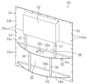
- FIG. 4 is a perspective view of the outer casing.
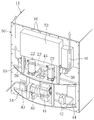
- FIG. 5 is a perspective view showing the trailer refrigeration apparatus with the front cover removed.
- FIG. 6 is a longitudinal sectional view showing a schematic configuration of the trailer refrigeration apparatus.
- FIG. 7 is a cross-sectional view showing the vicinity of the side edge of the open portion of the trailer.
- FIG. 8 is a perspective view showing the trailer refrigeration apparatus with the front cover removed, and shows the flow of outdoor air.
- FIG. 1 is an overall configuration diagram of a refrigeration vehicle and a trailer refrigeration apparatus.
- FIG. 2 is a schematic configuration diagram of a refrigerant circuit of the trailer refrigeration apparatus.
- FIG. 3 is a perspective view showing the entire configuration of the trailer opening and the trailer
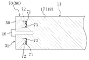
- FIG. 9 is a cross-sectional view showing the vicinity of the side edge of the open portion of the trailer in the trailer refrigeration apparatus of the modification.
- FIG. 10 is a longitudinal sectional view showing the vicinity of the upper edge portion (lower edge portion) of the trailer in the trailer refrigeration apparatus of another modified example. )
- the trailer refrigeration apparatus (20) of this embodiment is mounted on a refrigeration vehicle (10) for transporting frozen foods, fresh foods, and the like on land.
- the refrigeration vehicle (10) includes a trailer (11) that stores cargo such as frozen food, and a tractor (12) that pulls the trailer (11).
- the trailer (11) is formed in a box shape having a vertically long rectangular parallelepiped shape in the front-rear direction and an open front end.
- An interior space (13) is formed inside the trailer (11), and frozen food, fresh food, and the like are stored in the interior space (13).
- a rectangular frame-shaped opening (14) is formed at the front end of the trailer (11).
- a plurality of screwing portions (15, 15,%) are formed on the front end surface of the opening portion (14).
- the plurality of screwing portions (15, 15,...) Are arranged at regular intervals, for example, at 8 locations on each of the four sides of the opening portion (14).
- the trailer refrigeration apparatus (20) constitutes a cooling apparatus for cooling the air in the internal space (13) of the refrigeration vehicle (10).
- the trailer refrigeration apparatus (20) includes a refrigerant circuit (21) filled with a refrigerant.
- a compressor (22), a condenser (23), an expansion valve (24), and an evaporator (25) are connected to the refrigerant circuit (21).
- a refrigerant is circulated to perform a vapor compression refrigeration cycle.
- An outside fan (26) is provided in the vicinity of the condenser (23). In the condenser (23), the outside (outdoor) air conveyed by the outside fan (26) and the refrigerant exchange heat.
- An internal fan (27) is provided in the vicinity of the evaporator (25). In the evaporator (25), the internal air conveyed by the internal fan (27) and the refrigerant exchange heat.
- the evaporator (25) constitutes a cooling unit for cooling the air in the interior space (13) of the trailer (11).
- the trailer refrigerating apparatus (20) has a casing unit (31) attached to the open portion (14) of the trailer (11).
- the casing unit (31) includes a front cover (32), an external casing (50), and an internal casing (33).
- the front cover (32) is configured to be detachable from the front surface of the external casing (50).
- the front cover (32) is configured by an arcuate plate-like member in which an intermediate portion in the width direction (left-right direction in FIG. 3) bulges forward.
- the side part (32a, 32a) of the width direction both ends is hold
- the front cover (32) is provided with one central inlet (32b) and two side inlets (32c, 32c).
- the central introduction port (32b) is formed in the approximate center of the front cover (32).
- the side introduction ports (32c, 32c) are formed on the lower side of the front cover (32) and on the left and right ends, respectively.
- the outside casing (50) is provided outside the trailer (11).
- the outside casing (50) is made of an aluminum material.
- the outside casing (50) has a square plate-like base part (51) and a bulging part (52) formed in an upper part of the base part (51) (FIGS. 3, 4, and 4). (See FIG. 6).
- the base part (51) is configured by connecting three divided bodies (51a, 51b, 51c) in the vertical direction. That is, the base part (51) is located between the lower base part (51a) near the lower part, the upper base part (51b) near the upper part, and the lower base part (51a) and the upper base part (51b). It is comprised by the intermediate base part (51c) located.
- a plurality of bolt holes (53a, 53a,%) Through which the bolts (16) are inserted are formed in the outer edge portion (53) of the base portion (51).
- the plurality of bolt holes (53a, 53a,...) are arranged at equal intervals, for example, at eight locations on each of the four sides of the outer edge portion (53) of the base portion (51).
- the outer casing (50) is a bolt (16) that penetrates the bolt hole (53a) with the outer edge (53) of the base part (51) and the open part (14) of the trailer (11) in close contact with each other. Is fixed to the trailer (11) by fastening it to the screwing portion (15).
- the outside casing (50) functions as a closing member for the opening (14) of the trailer (11).
- the open part (14) of the trailer (11) is reinforced by the outer edge part (53) of the outer casing (50). That is, the outside casing (50) also functions as a reinforcing member for the open portion (14) of the trailer (11).
- the bulging portion (52) is made of an aluminum material that is integral with the base portion (51), and bulges forward from the base portion (51).
- the bulging portion (52) is formed in a box shape having a rectangular parallelepiped shape that is flat in the front-rear direction and opened on the rear surface side (see FIG. 6).
- the bulging portion (52) may be made of, for example, a resin material and integrally connected to the base portion (51).
- the outer casing (50) includes a lower plate (54) and an upper plate (55).
- the lower plate (54) is provided near the lower end of the base portion (51), and the upper plate (55) is an intermediate portion in the vertical direction of the base portion (51) (the lower plate (54) and the bulging portion ( 52).
- Each plate (54, 55) has an arcuate plate-like support plate portion (54a, 55a).
- the support plate portions (54a, 55a) are formed in a circular arc shape on the front side and in a straight line shape along the front surface of the base portion (51) on the rear side.
- Each plate (54, 55) has a bent portion (54b, 55b) bent upward from the rear end of the support plate portion (54a, 55a).
- the bent portions (54b, 55b) are formed in a plate shape extending in the left-right direction.
- Each plate (54, 55) is fixed to the base part (51) by the bent part (54b, 55b) being fixed to the base part (51) by a rivet.
- the support plate portion (55a) of the upper plate (55) is provided with a communication port (55c) at an intermediate portion in the left-right direction.
- the first machine chamber (35) is defined between the lower plate (54) and the upper plate (55).
- a second machine room (36) is defined above the upper plate (55).
- the first machine chamber (35) and the second machine chamber (36) communicate with each other via the communication port (55c) of the upper plate (55).
- the first machine room (35) communicates with the two side introduction ports (32c, 32c) described above, and the second machine room (36) communicates with the center introduction port (32b) described above. .
- the outer casing (50) includes two lower pillars (56) and two upper pillars (57).
- the lower column portion (56) is interposed between the lower plate (54) and the upper plate (55).
- the upper column part (57) is interposed between the upper plate (55) and the bulging part (52).
- Each column portion (56, 57) is made of an aluminum material and is formed in a prismatic shape extending vertically.
- a generator (40), an engine (41), a battery (42), and a plurality of electrical component boxes (43, 44) are provided in the first machine room (35) described above. Yes. Specifically, in the first machine room (35), a generator (40) and an engine (41) are installed at an intermediate position in the left-right direction of the lower plate (54). The engine (41) drives the generator (40), and the generator (40) generates electric power for driving the above-described compressor (22) and the like. In the first machine room (35), the first electrical component box (43) is provided in the left space of the generator (40), and the second electrical component box (in the right space of the engine (41) ( 44) is provided.
- the second machine room (36) is provided with two compressors (22), a condenser (23), a radiator (45), two external fans (26), and an electrical component box (46).
- two compressors (22) are installed at an intermediate position in the left-right direction of the upper plate (55).
- a radiator (45) and a condenser (23) are disposed in front of the compressor (22).
- the condenser (23) is disposed so as to straddle the two upper pillars (57).
- the central inlet (32b) of the front cover (32) is located in front of the condenser (23).
- the radiator (45) is disposed on the rear side of the condenser (23), and constitutes an air-cooled radiator for radiating heat from the engine (41).
- the two outside fans (26, 26) are arranged near the left and right ends of the upper plate (55) so as to sandwich the two compressors (22).
- the external fan (2) is a so-called propeller fan, and its rotation shaft extends to the left and right.
- a propeller is connected to the end near the compressor (22) and a motor is connected to the opposite end of the rotating shaft of the external fan (26).
- a third electrical component box (46) is provided in the space on the upper right side.
- the internal casing (33) is provided on the back side of the external casing (50) so as to face the internal space (13) of the trailer (11).
- the internal casing (33) is made of, for example, an FRP (glass fiber reinforced plastic) material. Note that the internal casing (33) can be made of other resin material, metal material, or the like.
- the internal casing (33) has a shape along the back surface of the external casing (50).
- the front surface of the inner casing (33) is spaced a predetermined distance from the rear surface of the outer casing (50), and a heat insulating member (34) is provided between the inner casing (33) and the outer casing (50). Is formed.
- the heat insulating member (34) is integrated with the casing unit (31) by forming a sealed space between the outer casing (50) and the inner casing (33) and then filling the sealed space with foamed resin. Formed.
- a partition member (37) is attached to the back side of the internal casing (33).
- the partition member (37) is disposed so as to have a predetermined distance from each of the back surface of the internal casing (33), the upper inner wall of the trailer (11), and the lower inner wall of the trailer (11).
- the inflow port (37a) is formed below the partition member (37)
- the outflow port (37b) is formed above the partition member (37).
- an internal air flow path (38) is formed between the internal casing (33) and the partition member (37) so as to straddle the inflow port (37a) and the outflow port (37b).
- the inside air flow path (38) is provided with the evaporator (25) and the internal fan (27) described above.
- the evaporator (25) is disposed on the back side of the bulging portion (52) so as to straddle between the inner casing (33) and the partition member (37) and supported by the inner casing (33). ing.
- the internal fan (27) is provided above the evaporator (25).
- FIG. 7 is an enlarged view of the horizontal section in the vicinity of the side edge (14a) (see FIG. 2) on both sides of the left and right width direction of the trailer (11).
- the groove (61) extends in the vertical direction so as to straddle the lower edge (18) from the upper edge (17) of the open part (14) of the trailer (11), and the horizontal section is formed in a rectangular shape. Yes.
- the two groove portions (61, 61) extend in parallel so as to be spaced apart from each other.
- the outer casing (50) of the casing unit (31) is formed with two convex portions (62, 62) (vertical convex portions) that fit into the groove portion (61).
- the convex portion (62) extends in the vertical direction from the upper end to the lower end of the external casing (50), and the horizontal section is formed in a rectangular shape.
- the two convex portions (62, 62) extend in parallel so as to be spaced apart from each other. That is, each convex part (62) has a shape corresponding to each groove part (61) on the trailer (11) side, and is configured to fit into each groove part (61) at the time of attachment.
- the bolt (16) described above is provided at an intermediate position between the two groove portions (61, 61) and the two convex portions (62, 62). That is, the two groove portions (61, 61) or the two convex portions (62, 62) sandwich the plurality of bolts (16) arranged in the vertical direction, and the arrangement direction of the plurality of bolts (16). It extends to.
- a seal member (63) (vertical seal member) is interposed between the groove portion (61) and the convex portion (62) in the attached state.
- this seal member (63) for example, packing, silicon seal or the like is used.
- This seal member (63) allows the cool air in the interior space (13) of the trailer (11) to pass through the gap between the side edge (14a) of the trailer (11) and the outer casing (50). Leakage is prevented.
- a seal rubber (64) as a seal member is provided between the side end of the internal casing (33) and the side edge (14a) of the open portion (14) of the trailer (11). ) Is provided. Further, silicon is applied to the contact portion between the side end of the outer casing (50) and the side edge (14a) of the trailer (11). As described above, in the attachment portion (60), cold air leakage from the internal space (13) to the outside of the internal space is prevented.
- the refrigerant compressed by the compressor (22) flows through the condenser (23).
- the condenser (23) the refrigerant dissipates heat to the outside air and condenses.
- the condensed refrigerant is decompressed by passing through the expansion valve (24), and the decompressed refrigerant flows through the evaporator (25).
- the evaporator (25) the refrigerant absorbs heat from the internal air and evaporates.
- the evaporated refrigerant is compressed again by the compressor (22).
- the internal air in the internal space (13) is sucked into the internal air flow path (38) from the inlet (37a).
- the air sucked into the inside air flow path (38) flows upward and passes through the evaporator (25).
- the internal air is cooled by exchanging heat with the refrigerant.
- the internal air cooled by the evaporator (25) flows out from the outlet (37b) into the internal space (S) and is used for refrigeration / freezing of cargo and the like.
- the air sucked into the second machine room (36) from the central inlet (32b) passes through the condenser (23).
- the refrigerant dissipates heat to the outside air and condenses.
- the air that has passed through the condenser (23) flows around the radiator (45), is used for cooling the radiator (45), and merges with the air that has passed through the communication port (55c).
- the air after merging in the second machine room (36) is diverted in the left-right direction so as to flow around the two compressors (22, 22).
- the air diverted to the left side passes through the upper end opening in the front cover (32) and is discharged to the outside of the external casing (50).
- the air divided to the right side passes through the third electrical component box (46), then passes through the upper end opening in the front cover (32) and is discharged to the outside of the external casing (50).
- the convex portion (62) into the groove portion (61)
- the cold air in the internal space (13) is less likely to leak to the outside.
- the seal member (63) between the groove (61) and the convex portion (62) the sealing effect of cold air leakage is improved.
- the groove (61) is formed on both the left and right sides of the bolt (16). For this reason, even if the clearance around the bolt (16) becomes wider as the bolt (16) is fastened, the cold air leakage can be prevented by the groove (61) and the convex portion (62).
- the sealing member (packing (63)) between the groove (61) and the projection (62) is consolidated, further improving the sealing effect of the sealing member (63). it can.
- the groove (61) and the convex (62) function as a positioning part for the casing unit (31) and the trailer (11). That is, when attaching the casing unit (31) to the trailer (11), the bolt hole (53a) on the outer casing (50) side and the trailer ( 11) It can be aligned with the screwing part (15) on the side. Thereby, the fastening operation
- the casing unit (31) of the above embodiment a modified structure as shown in FIG. 9 may be adopted. That is, in the casing unit (31), the base part (51) of the outer casing (50) is made of an aluminum material separate from the outer edge part (53), and the base part (51) and the outer edge part (53) are formed. They are connected together. Further, in the outer casing (50) of the modified example, a square columnar reinforcing portion (58) is formed at the outer edge portion (53). The reinforcing part (58) extends in the vertical direction from the upper end to the lower end of the external casing (50). In this modification, the rigidity of the opening part (14) of the casing unit (31) and the trailer (11) can be further improved by forming the reinforcing part (58).
- the groove part (61) and convex part (62) which are extended to the attachment part (60) of the side edge part (14a) of the open part (14) of a trailer (11), and a casing (31) (62). ) Is formed.
- the part (72) (lateral convex part) may be formed.
- two grooves (71, 71) are formed on the front surface of the upper edge (17) of the casing (31).
- the groove portion (71) extends in the horizontal direction so as to extend to the left and right side edge portions (14a, 14a) of the open portion (14) of the trailer (11), and the longitudinal section is formed in a rectangular shape.
- the two groove portions (71, 71) extend in parallel so as to be spaced apart from each other.
- each convex portion (72) in the example of FIG. 10 has a shape corresponding to each groove portion (71) on the trailer (11) side, and is fitted to each groove portion (71) at the time of attachment. It is configured.
- the bolt (16) is provided at an intermediate position between the two groove portions (71, 71) and the two convex portions (72, 72). That is, the two groove portions (71, 71) or the two convex portions (72, 72) sandwich the plurality of bolts (16) arranged in the horizontal direction, and the arrangement direction of the plurality of bolts (16). It extends to.
- a seal member (73) (lateral seal member) is interposed between the groove portion (71) and the convex portion (72) in the attached state.
- this seal member (73) for example, packing, silicon seal or the like is used.
- the groove (71) and the protrusion (72) are also formed in the upper edge (17) and the lower edge (18) of the trailer (11).
- the longitudinal strength can be improved.
- the sealing performance between the open part (14) of the trailer (11) and the casing unit (31) can be further improved, and cold air leakage can be reliably prevented.
- the groove part (61,71) is formed in the trailer (11) side and the convex part (62,72) is formed in the casing unit (31) side, it is in the trailer (11) side.
- a convex part (62, 72) may be formed and a groove part (61, 71) may be formed in the casing unit (31) side.
- the present invention is useful for a trailer refrigeration apparatus that cools the interior space of a trailer.
Landscapes
- Engineering & Computer Science (AREA)
- Physics & Mathematics (AREA)
- Thermal Sciences (AREA)
- Mechanical Engineering (AREA)
- Chemical & Material Sciences (AREA)
- Combustion & Propulsion (AREA)
- General Engineering & Computer Science (AREA)
- Health & Medical Sciences (AREA)
- Public Health (AREA)
- Transportation (AREA)
- Devices That Are Associated With Refrigeration Equipment (AREA)
- Refrigerator Housings (AREA)
Abstract
Priority Applications (4)
| Application Number | Priority Date | Filing Date | Title |
|---|---|---|---|
| CN201080025062.8A CN102449418B (zh) | 2009-06-10 | 2010-06-04 | 拖车用制冷装置 |
| US13/377,179 US9285158B2 (en) | 2009-06-10 | 2010-06-04 | Trailer refrigerating apparatus |
| JP2011518290A JP5706819B2 (ja) | 2009-06-10 | 2010-06-04 | トレーラ用冷凍装置 |
| EP10785922.5A EP2442055B1 (fr) | 2009-06-10 | 2010-06-04 | Dispositif de réfrigération pour remorque |
Applications Claiming Priority (2)
| Application Number | Priority Date | Filing Date | Title |
|---|---|---|---|
| JP2009139512 | 2009-06-10 | ||
| JP2009-139512 | 2009-06-10 |
Publications (1)
| Publication Number | Publication Date |
|---|---|
| WO2010143390A1 true WO2010143390A1 (fr) | 2010-12-16 |
Family
ID=43308653
Family Applications (1)
| Application Number | Title | Priority Date | Filing Date |
|---|---|---|---|
| PCT/JP2010/003753 Ceased WO2010143390A1 (fr) | 2009-06-10 | 2010-06-04 | Dispositif de réfrigération pour remorque |
Country Status (5)
| Country | Link |
|---|---|
| US (1) | US9285158B2 (fr) |
| EP (1) | EP2442055B1 (fr) |
| JP (1) | JP5706819B2 (fr) |
| CN (1) | CN102449418B (fr) |
| WO (1) | WO2010143390A1 (fr) |
Cited By (1)
| Publication number | Priority date | Publication date | Assignee | Title |
|---|---|---|---|---|
| JP2021055942A (ja) * | 2019-09-30 | 2021-04-08 | ダイキン工業株式会社 | コンテナ用冷凍装置 |
Families Citing this family (3)
| Publication number | Priority date | Publication date | Assignee | Title |
|---|---|---|---|---|
| US10507708B2 (en) | 2014-02-03 | 2019-12-17 | Carrier Corporation | Vertical sliding solution of the condenser unit for trucks with refrigerated goods |
| EP3284660B1 (fr) * | 2016-08-15 | 2019-10-09 | Schmitz Cargobull AG | Superstructure de vehicule utilitaire comprenant une machine frigorifique de transport integree |
| US11554640B2 (en) | 2020-06-30 | 2023-01-17 | Thermo King Llc | Isolated evaporator coil for a transport climate control system |
Citations (6)
| Publication number | Priority date | Publication date | Assignee | Title |
|---|---|---|---|---|
| JPH07151453A (ja) * | 1993-11-30 | 1995-06-16 | Sanyo Electric Co Ltd | 組立式断熱箱体のパネル結合方法及び結合装置 |
| JPH0875345A (ja) * | 1994-08-31 | 1996-03-19 | Sanyo Electric Co Ltd | 組立式冷却貯蔵庫 |
| JPH09251570A (ja) * | 1995-12-29 | 1997-09-22 | Lg Sanden Kk | 自動販売機の断熱パネル組立体 |
| JPH10132454A (ja) * | 1996-10-28 | 1998-05-22 | Yodogawa Steel Works Ltd | 組立式冷蔵庫のパネルの直角接合構造 |
| JP2005180718A (ja) * | 2003-12-16 | 2005-07-07 | Matsushita Electric Ind Co Ltd | 冷蔵庫 |
| JP2009052833A (ja) | 2007-08-28 | 2009-03-12 | Daikin Ind Ltd | トレーラ用冷凍装置 |
Family Cites Families (15)
| Publication number | Priority date | Publication date | Assignee | Title |
|---|---|---|---|---|
| DE2529801A1 (de) * | 1974-07-10 | 1976-02-05 | Teruo Ohashi | Vorgefertigter kuehl- und gefrierschrank |
| US4365484A (en) * | 1981-02-24 | 1982-12-28 | Carrier Corporation | Transport refrigeration machine |
| US4567734A (en) * | 1984-08-31 | 1986-02-04 | Danhard, Inc. | Air deflector-air conditioner condenser integrated unit |
| JPH08337285A (ja) * | 1995-06-13 | 1996-12-24 | Daikin Ind Ltd | 冷凍コンテナ用冷凍装置のケーシング構造 |
| DE29511557U1 (de) * | 1995-07-19 | 1995-09-28 | Sattlberger, Michael, 83122 Samerberg | Eckverbindung für in Blockbauweise errichtete Bauten |
| DE29517351U1 (de) * | 1995-10-30 | 1996-01-04 | Ingenieurbüro für Umwelttechnik Fa. Horst Qualmann, 21423 Winsen | Universal-CA-Aggregat zur Erzeugung einer kontrollierten Atmosphäre in einem Container |
| JPH10318668A (ja) * | 1997-05-19 | 1998-12-04 | Hoshizaki Electric Co Ltd | 断熱パネルの連結構造 |
| JP3309767B2 (ja) * | 1997-06-24 | 2002-07-29 | ダイキン工業株式会社 | コンテナ用冷凍装置の電気品箱構造 |
| JP2001241835A (ja) * | 2000-03-02 | 2001-09-07 | Mitsubishi Heavy Ind Ltd | 陸上輸送用冷凍装置 |
| DE10127039A1 (de) * | 2001-06-02 | 2002-12-12 | Aeg Hausgeraete Gmbh | Kühl- und/oder Gefriervorrichtung |
| US7578534B2 (en) * | 2005-11-03 | 2009-08-25 | Martin Marietta Materials, Inc. | Structural panel for a refrigerated trailer comprising an integrated bulkhead structure for promoting air flow |
| KR100700612B1 (ko) * | 2006-01-03 | 2007-03-28 | 엘지전자 주식회사 | 조립식 냉장고의 단열 판넬의 결합 구조 및 이를 구비한조립식 냉장고 |
| US7654055B2 (en) * | 2006-08-08 | 2010-02-02 | Ricker Michael B | Glueless panel locking system |
| KR20110021937A (ko) * | 2008-05-23 | 2011-03-04 | 악티에볼라겟 엘렉트로룩스 | 냉각 기기 |
| EP2436543B1 (fr) * | 2009-05-25 | 2018-09-05 | Daikin Industries, Ltd. | Dispositif de réfrigération pour remorque |
-
2010
- 2010-06-04 JP JP2011518290A patent/JP5706819B2/ja not_active Expired - Fee Related
- 2010-06-04 EP EP10785922.5A patent/EP2442055B1/fr active Active
- 2010-06-04 CN CN201080025062.8A patent/CN102449418B/zh active Active
- 2010-06-04 US US13/377,179 patent/US9285158B2/en not_active Expired - Fee Related
- 2010-06-04 WO PCT/JP2010/003753 patent/WO2010143390A1/fr not_active Ceased
Patent Citations (6)
| Publication number | Priority date | Publication date | Assignee | Title |
|---|---|---|---|---|
| JPH07151453A (ja) * | 1993-11-30 | 1995-06-16 | Sanyo Electric Co Ltd | 組立式断熱箱体のパネル結合方法及び結合装置 |
| JPH0875345A (ja) * | 1994-08-31 | 1996-03-19 | Sanyo Electric Co Ltd | 組立式冷却貯蔵庫 |
| JPH09251570A (ja) * | 1995-12-29 | 1997-09-22 | Lg Sanden Kk | 自動販売機の断熱パネル組立体 |
| JPH10132454A (ja) * | 1996-10-28 | 1998-05-22 | Yodogawa Steel Works Ltd | 組立式冷蔵庫のパネルの直角接合構造 |
| JP2005180718A (ja) * | 2003-12-16 | 2005-07-07 | Matsushita Electric Ind Co Ltd | 冷蔵庫 |
| JP2009052833A (ja) | 2007-08-28 | 2009-03-12 | Daikin Ind Ltd | トレーラ用冷凍装置 |
Non-Patent Citations (1)
| Title |
|---|
| See also references of EP2442055A4 * |
Cited By (3)
| Publication number | Priority date | Publication date | Assignee | Title |
|---|---|---|---|---|
| JP2021055942A (ja) * | 2019-09-30 | 2021-04-08 | ダイキン工業株式会社 | コンテナ用冷凍装置 |
| WO2021065119A1 (fr) * | 2019-09-30 | 2021-04-08 | ダイキン工業株式会社 | Dispositif de réfrigération pour contenants |
| US11668509B2 (en) | 2019-09-30 | 2023-06-06 | Daikin Industries, Ltd. | Container refrigeration apparatus |
Also Published As
| Publication number | Publication date |
|---|---|
| JP5706819B2 (ja) | 2015-04-22 |
| JPWO2010143390A1 (ja) | 2012-11-22 |
| US20120080162A1 (en) | 2012-04-05 |
| CN102449418A (zh) | 2012-05-09 |
| EP2442055A1 (fr) | 2012-04-18 |
| EP2442055A4 (fr) | 2016-01-13 |
| CN102449418B (zh) | 2016-03-02 |
| EP2442055B1 (fr) | 2019-05-15 |
| US9285158B2 (en) | 2016-03-15 |
Similar Documents
| Publication | Publication Date | Title |
|---|---|---|
| WO2010137258A1 (fr) | Dispositif de réfrigération pour remorque | |
| JP5428551B2 (ja) | トレーラ用冷凍装置 | |
| JP5453943B2 (ja) | トレーラ用冷凍装置 | |
| JP2009052833A (ja) | トレーラ用冷凍装置 | |
| WO2010143407A1 (fr) | Dispositif de réfrigération pour transport | |
| JP5706819B2 (ja) | トレーラ用冷凍装置 | |
| JP5476805B2 (ja) | トレーラ用冷凍装置 | |
| US20120251348A1 (en) | Motor-driven compressor | |
| WO2008018360A1 (fr) | Remorque et machine frigorifique pour remorque | |
| JP4254908B2 (ja) | コンテナ用冷凍機 | |
| JP5476813B2 (ja) | トレーラ用冷凍装置 | |
| JP5521410B2 (ja) | トレーラ用冷凍装置 | |
| JP7668893B2 (ja) | 輸送用冷凍機ユニット | |
| JP6863427B2 (ja) | コンテナ用冷凍装置 | |
| JP7642090B2 (ja) | 輸送用冷凍機ユニット | |
| TWI542500B (zh) | Frame construction of refrigeration device for vehicle | |
| HK1179222A1 (zh) | 车载用制冷装置的框架结构 | |
| HK1179222B (en) | Frame structure for vehicle-mounted refrigerating device | |
| JP2009024908A (ja) | コンテナ用冷凍装置及びその製造方法 |
Legal Events
| Date | Code | Title | Description |
|---|---|---|---|
| WWE | Wipo information: entry into national phase |
Ref document number: 201080025062.8 Country of ref document: CN |
|
| 121 | Ep: the epo has been informed by wipo that ep was designated in this application |
Ref document number: 10785922 Country of ref document: EP Kind code of ref document: A1 |
|
| WWE | Wipo information: entry into national phase |
Ref document number: 2011518290 Country of ref document: JP |
|
| WWE | Wipo information: entry into national phase |
Ref document number: 13377179 Country of ref document: US |
|
| NENP | Non-entry into the national phase |
Ref country code: DE |
|
| WWE | Wipo information: entry into national phase |
Ref document number: 2010785922 Country of ref document: EP |