WO2010143438A1 - Dispositif de commande, barillet de lentille et appareil photo - Google Patents
Dispositif de commande, barillet de lentille et appareil photo Download PDFInfo
- Publication number
- WO2010143438A1 WO2010143438A1 PCT/JP2010/003875 JP2010003875W WO2010143438A1 WO 2010143438 A1 WO2010143438 A1 WO 2010143438A1 JP 2010003875 W JP2010003875 W JP 2010003875W WO 2010143438 A1 WO2010143438 A1 WO 2010143438A1
- Authority
- WO
- WIPO (PCT)
- Prior art keywords
- piezoelectric element
- phase
- driving
- rotor
- voltage
- Prior art date
- Legal status (The legal status is an assumption and is not a legal conclusion. Google has not performed a legal analysis and makes no representation as to the accuracy of the status listed.)
- Ceased
Links
Images


Classifications
-
- H—ELECTRICITY
- H02—GENERATION; CONVERSION OR DISTRIBUTION OF ELECTRIC POWER
- H02N—ELECTRIC MACHINES NOT OTHERWISE PROVIDED FOR
- H02N2/00—Electric machines in general using piezoelectric effect, electrostriction or magnetostriction
- H02N2/10—Electric machines in general using piezoelectric effect, electrostriction or magnetostriction producing rotary motion, e.g. rotary motors
- H02N2/101—Electric machines in general using piezoelectric effect, electrostriction or magnetostriction producing rotary motion, e.g. rotary motors using intermittent driving, e.g. step motors
-
- G—PHYSICS
- G02—OPTICS
- G02B—OPTICAL ELEMENTS, SYSTEMS OR APPARATUS
- G02B7/00—Mountings, adjusting means, or light-tight connections, for optical elements
- G02B7/02—Mountings, adjusting means, or light-tight connections, for optical elements for lenses
- G02B7/04—Mountings, adjusting means, or light-tight connections, for optical elements for lenses with mechanism for focusing or varying magnification
- G02B7/10—Mountings, adjusting means, or light-tight connections, for optical elements for lenses with mechanism for focusing or varying magnification by relative axial movement of several lenses, e.g. of varifocal objective lens
- G02B7/102—Mountings, adjusting means, or light-tight connections, for optical elements for lenses with mechanism for focusing or varying magnification by relative axial movement of several lenses, e.g. of varifocal objective lens controlled by a microcomputer
-
- G—PHYSICS
- G03—PHOTOGRAPHY; CINEMATOGRAPHY; ANALOGOUS TECHNIQUES USING WAVES OTHER THAN OPTICAL WAVES; ELECTROGRAPHY; HOLOGRAPHY
- G03B—APPARATUS OR ARRANGEMENTS FOR TAKING PHOTOGRAPHS OR FOR PROJECTING OR VIEWING THEM; APPARATUS OR ARRANGEMENTS EMPLOYING ANALOGOUS TECHNIQUES USING WAVES OTHER THAN OPTICAL WAVES; ACCESSORIES THEREFOR
- G03B3/00—Focusing arrangements of general interest for cameras, projectors or printers
- G03B3/02—Focusing arrangements of general interest for cameras, projectors or printers moving lens along baseboard
-
- G—PHYSICS
- G03—PHOTOGRAPHY; CINEMATOGRAPHY; ANALOGOUS TECHNIQUES USING WAVES OTHER THAN OPTICAL WAVES; ELECTROGRAPHY; HOLOGRAPHY
- G03B—APPARATUS OR ARRANGEMENTS FOR TAKING PHOTOGRAPHS OR FOR PROJECTING OR VIEWING THEM; APPARATUS OR ARRANGEMENTS EMPLOYING ANALOGOUS TECHNIQUES USING WAVES OTHER THAN OPTICAL WAVES; ACCESSORIES THEREFOR
- G03B3/00—Focusing arrangements of general interest for cameras, projectors or printers
- G03B3/10—Power-operated focusing
-
- G—PHYSICS
- G03—PHOTOGRAPHY; CINEMATOGRAPHY; ANALOGOUS TECHNIQUES USING WAVES OTHER THAN OPTICAL WAVES; ELECTROGRAPHY; HOLOGRAPHY
- G03B—APPARATUS OR ARRANGEMENTS FOR TAKING PHOTOGRAPHS OR FOR PROJECTING OR VIEWING THEM; APPARATUS OR ARRANGEMENTS EMPLOYING ANALOGOUS TECHNIQUES USING WAVES OTHER THAN OPTICAL WAVES; ACCESSORIES THEREFOR
- G03B2205/00—Adjustment of optical system relative to image or object surface other than for focusing
- G03B2205/0053—Driving means for the movement of one or more optical element
- G03B2205/0061—Driving means for the movement of one or more optical element using piezoelectric actuators
Definitions
- the present invention relates to a drive device, a lens barrel, and a camera.
- This application claims priority based on Japanese Patent Application No. 2009-139564 filed in Japan on June 10, 2009 and Japanese Patent Application No. 2009-256371 filed in Japan on November 9, 2009. The contents are incorporated herein.
- Patent Document 1 discloses a device that drives a driven body by driving a plurality of piezoelectric elements and causing an elliptical movement of a tip member that contacts the driven body.
- Patent Document 1 when an XYZ orthogonal coordinate system is set, the driven body is driven in the X-axis direction by an elliptical motion parallel to the XZ plane of the chip member.
- the conventional drive device has a problem that vibrations in two different directions cannot be extracted as independent vibrations.
- Patent Document 1 since vibrations in the X-axis direction and the Z-axis direction of the chip member cannot be extracted as independent vibrations, a plurality of piezoelectric elements may interfere with each other's movement. When the plurality of piezoelectric elements are driven so as to prevent each other's movement, the output of the driving device that drives the driven body decreases.
- the base member that supports the piezoelectric element is provided with conductive WC (tungsten carbide) or the like.
- conductive WC tungsten carbide
- the base member becomes a common electrode, and the potentials of the electrodes of the plurality of piezoelectric elements in contact with the base member are equal. Therefore, there is a problem that it is difficult to apply different voltages to the plurality of piezoelectric elements.
- An aspect of the present invention aims to provide a driving device that can extract vibrations in two different directions as independent vibrations, and a lens barrel and a camera using the driving device.
- a driving device that can easily apply different voltages to a piezoelectric element, and a lens barrel and a camera using the same even when a member supporting the piezoelectric element has conductivity. Objective.
- a drive device is a drive device that relatively drives a first member and a second member, the piezoelectric element that drives the first member, and the first member via the piezoelectric element.
- a base portion that is drivably supported and an electrode portion to which a driving voltage of the piezoelectric element is applied, and the electrode portion has an exposed portion that is exposed from the base portion.
- a drive device is provided by contacting a piezoelectric element, a first member driven by the piezoelectric element, and the first member, and driving the first member, A second member that moves relative to the first member; a base member that is electrically conductive and supports the first member via the piezoelectric element; and the first member and the piezoelectric element. And an insulating film is provided between at least one of the piezoelectric elements of the set and the base member.
- a lens barrel according to still another aspect of the present invention includes the drive device described above.
- a camera includes the drive device described above.
- the drive device can extract vibrations in two different directions as independent vibrations.
- At least one set of piezoelectric elements and the base member are electrically insulated by the insulating film, and different voltages are applied to the set of piezoelectric elements and the other sets of piezoelectric elements. It can be applied easily.
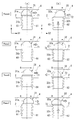
- FIG. It is a front view of the drive device concerning a 1st embodiment of the present invention.
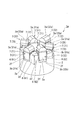
- FIG. It is a perspective view of the support drive part of the drive device shown in FIG.
- FIG. It is a front view of the holding
- FIG. It is a front view of the holding
- FIG. It is a perspective view of the holding
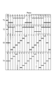
- 3 is a timing chart of voltages supplied by a power supply unit of the drive device shown in FIG. 1. It is a front view which shows the operation
- FIG. It is a graph which shows the time change of the displacement of the front-end
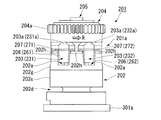
- FIG. FIG. 18 is an enlarged cross-sectional view of a drive piece and a base portion of the drive device shown in FIG. 17. It is a perspective view which shows the support drive part of the drive device shown in FIG. It is a top view which shows the support drive part of the drive device shown in FIG. It is a circuit diagram of the drive device shown in FIG. It is a circuit diagram of the drive device shown in FIG. It is a circuit diagram of the drive device shown in FIG. It is a timing chart of the voltage which the power supply part of the drive device shown in FIG. 17 supplies. It is a front view which shows operation
- the drive device 1 concerning the 1st Embodiment of this invention is demonstrated below, referring drawings.
- the driving device 1 performs relative driving that relatively displaces a first member such as a driving piece and a second member such as a rotor, so that an optical device or an electronic device such as a lens barrel of a camera is performed. It is for driving.
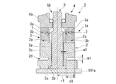
- FIG. 1 is a front view of the drive device 1 of the present embodiment
- FIG. 2 is a cross-sectional view thereof.
- the driving device 1 includes a base portion (base member) 2 provided with a plurality of holding portions 2a, a driving piece (first member) 3 held by the holding portion 2a, A rotor (second member) 4 disposed adjacent to the drive piece 3 and a support shaft 5 inserted through the base portion 2 are provided.
- the base portion 2 is formed in a hollow cylindrical shape from a metal material such as stainless steel, and is provided so as to surround the support shaft 5 by inserting the support shaft 5.
- a metal material such as stainless steel
- an insulating film or the like is formed on the surface of the base portion 2 and subjected to an insulation treatment.
- the rotor 4 is pivotally supported by a support shaft 5 via a bearing 5b, and is rotatably provided with the support shaft 5 as a rotation axis.
- a gear 4a for driving a lens barrel of a camera is formed on the outer peripheral surface of the rotor 4.
- the surface of the rotor 4 on the base portion 2 side is supported by a plurality of driving pieces 3.
- One end portion of the base portion 2 is fixed to the mounting portion 101a with, for example, a bolt (not shown).
- a concave portion 2b is formed in the central portion of the surface of the base portion 2 facing the mounting portion 101a.
- An enlarged diameter portion 5 a formed at the base end of the support shaft 5 is inserted (inserted) into the recess 2 b.
- the base portion 2 is fixed to the attachment portion 101a, whereby the support shaft 5 is fixed to the base portion 2 and the attachment portion 101a.
- a plurality of concave holding parts 2 a are provided in the circumferential direction of the base part 2, that is, in the rotation direction R of the rotor 4.
- the holding portion 2a supports the drive piece 3 from both sides in the direction (first direction) perpendicular to the support shaft 5 and along the rotation direction R of the rotor 4 (first direction), and also supports the drive piece 3 in a direction parallel to the support shaft 5 (first direction). 2) is drivable.
- a chamfered portion (exposed forming portion) 2 h is provided at a corner portion of the end portion of the base portion 2 on the rotor 4 side.
- the chamfered portion 2 h is provided over the entire circumference of the base portion 2 at both the outer peripheral corner portion and the inner peripheral corner portion of the end portion of the base portion 2 on the rotor 4 side.
- the side surface 2 c of the base portion 2 is provided substantially parallel to the support shaft 5.
- a groove portion 2d is formed as a vibration suppressing portion that suppresses transmission of vibration from the mounting portion 101a to the holding portion 2a. That is, the groove 2 d is provided on the side surface 2 c of the base 2 that is substantially perpendicular to the support shaft 5 and intersects the direction along the rotation direction R of the rotor 4 (first direction).
- the groove portion 2d is provided continuously in the circumferential direction of the base portion 2, and is provided at a position closer to the end portion on the attachment portion 101a side than the middle between the holding portion 2a and the end portion on the attachment portion 101a side.
- the depth d1 of the groove 2d is, for example, in the range of 40% or more and 80% or less of the radius r1 of the base 2.
- the above numerical value is an example, and the present invention is not limited to this.
- the depth d1 of the groove 2d can be, for example, 10, 20, 30, 40, 50, 60, 70, 80, or 90% of the radius r1 of the base 2.
- the width w1 of the groove 2d in the direction parallel to the support shaft 5 (second direction) is larger than the amplitude of vibration of the base 2, and the first piezoelectric element 6, the second piezoelectric element 7, and the driving piece to be described later. 3 and the support drive part (structure part) 1a comprising the base part 2 are formed so as to be larger than the amplitude of resonance vibration.
- the width w1 of the groove 2d can be shorter than the radius of the base 2.
- a gap (vibration suppressing portion) 2e for suppressing vibration from the mounting portion 101a to the holding portion 2a is provided between the base portion 2 and the support shaft 5.
- the gap 2e is provided in the direction parallel to the support shaft 5 from the end portion on the holding portion 2a side of the base portion 2 to the same position as the edge on the mounting portion 101a side of the groove portion 2d.
- the width w2 of the gap 2e is formed to be larger than the amplitude of vibration of the base portion 2 and larger than the amplitude of resonance vibration of the support driving portion 1a described later. .
- the drive piece 3 has a tip portion 3 a having a hexagonal column shape with a mountain-shaped cross section and a base portion 3 b having a substantially rectangular parallelepiped shape.
- the tip portion 3a is formed of, for example, stainless steel.
- the base 3b is made of, for example, a light metal alloy. Both the tip portion 3a and the base portion 3b have conductivity.
- the base portion 3b is supported by the holding portion 2a so as to be drivable in a direction parallel to the support shaft 5.
- the distal end portion 3a protrudes from the holding portion 2a and supports the rotor 4.
- the tip 3a is provided in a tapered shape in which the area of the upper surface that contacts the rotor 4 is smaller than the area of the bottom surface on the base 3b side.
- the width w3 direction of the drive piece 3 is a direction perpendicular to the support shaft 5 and along the rotation direction R of the rotor 4, and is substantially perpendicular to the center line CL in plan view of the base portion 2.
- the first piezoelectric element 6 is formed in an elongated rectangular shape extending along the depth d2 direction of the holding portion 2a, and is sandwiched between the base portion 3b and the holding portion 2a. Thereby, the first piezoelectric element 6 is disposed between the groove 4 d (see FIGS. 1 and 2) provided in the base portion 2 and the rotor 4.
- the first piezoelectric element 6 is bonded to the base portion 3b and the holding portion 2a of the driving piece 3 with, for example, a conductive adhesive.
- the two first piezoelectric elements 6 and 6 arranged in the depth p1 direction of the driving piece 3 substantially parallel to the center line CL passing through the center of the base portion 2 are substantially parallel to each other. All the first piezoelectric elements 6 have substantially the same shape and size.
- a pair of second piezoelectric elements 7 and 7 are provided substantially parallel to each other between the base 3 b and the tip 3 a of the driving piece 3.
- the second piezoelectric element 7 is formed in an elongated rectangular shape extending substantially parallel to the direction of the width w3 of the driving piece 3.
- the second piezoelectric element 7 is sandwiched between the bottom surface of the tip portion 3a and the top surface of the base portion 3b, and is bonded to the bottom surface of the tip portion 3a and the top surface of the base portion 3b with, for example, a conductive adhesive. All the second piezoelectric elements 7 have substantially the same shape and size.
- the first piezoelectric element 6 and the second piezoelectric element 7 are made of, for example, lead zirconate titanate (PZT), and the vibration mode is thickness shear vibration. That is, the first piezoelectric element 6 drives the drive piece 3 relative to the base portion 2 in the direction of the depth d2 of the holding portion 2a substantially parallel to the support shaft 5.
- the second piezoelectric element 7 drives the tip 3 a of the drive piece 3 in the width w3 direction (third direction) of the drive piece 3 relative to the base 3 b and the base 2. That is, in the present embodiment, the direction in which the first piezoelectric element 6 sandwiches the drive piece 3 (first direction) and the direction in which the second piezoelectric element 7 drives the tip 3a of the drive piece 3 (third direction). And are almost equal.
- the plurality of first piezoelectric elements 6, second piezoelectric elements 7, drive piece 3, and base portion 2 support the rotor 4 and drive the rotor 4 relative to the drive piece 3 and the base portion 2.
- Part 1a is configured.
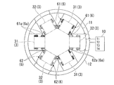
- the holding portion 2 a is provided at the end of the base portion 2, and has a crown-shaped unevenness on the base portion 2. As shown in FIG. 4, the holding portions 2 a are formed uniformly every approximately 60 ° in the circumferential direction of the base portion 2.
- the holding portion 2a includes a pair of support surfaces 2f and 2f provided substantially parallel to a center line CL passing through the center of the base portion 2 in plan view.
- the support surface 2f connects the base 3b of the drive piece 3 to the pair of first piezoelectric elements 6 and 6 from both sides in the width w4 direction (first direction) of the holding portion 2a substantially perpendicular to the center line CL of the base portion 2. It is held so that it is pinched.
- FIG. 5A is an enlarged front view of the holding unit 2a and the driving piece 3
- FIG. 5B is an enlarged front view of the holding unit 2a and the driving piece 3.
- the support surface 2f of the concave holding portion 2a provided on the base portion 2 is formed in the direction of the depth d2 of the holding portion 2a substantially parallel to the support shaft 5 shown in FIG. It is provided to be inclined with respect to the direction).
- the support surface 2f is inclined so that the distance between the opposing support surfaces 2f and 2f gradually decreases as the distance from the rotor 4 supported by the tip 3a of the drive piece 3 shown in FIG. 1 increases.
- the width w4 of the holding portion 2a becomes narrower as it approaches the bottom surface 2g.
- the inclination angle ⁇ of the support surface 2f with respect to the direction of the depth d2 of the holding portion 2a is preferably 2 ° or more and 6 ° or less in consideration of the dimensions and tolerances of each member.
- the inclination angle ⁇ of the support surface is 4 °.
- the side surface 3c of the base 3b of the drive piece 3 facing the support surface 2f is similar to the support surface 2f in the height h1 of the drive piece 3 substantially parallel to the support shaft 5. Inclined with respect to the direction (second direction). Thereby, the side surface 3c of the base 3b of the drive piece 3 is provided substantially parallel to the support surface 2f.
- the 1st piezoelectric element 6 provided with the electrode part 6a is previously joined to the side surface 3c via the electroconductive adhesive agent. 1 to 4, the illustration of the electrode portion 6a is omitted.
- the width w5 of the base 3b and the pair of first piezoelectric elements 6 and 6 at the end on the bottom surface 2g side of the holding portion 2a of the base 3b is smaller than the width w4 at the opening of the holding portion 2a, and the holding portion 2a. Is larger than the width w4 ′ in the middle of the depth d2 direction.
- the base 3b of the drive piece 3 and the pair of first piezoelectric elements 6 and 6 are held by the holding part 2a, the bottom face 3d of the drive piece 3 and the bottom face 2g of the holding part 2a are separated as shown in FIG. 5B.
- the base 3b is supported by the support surface 2f via the pair of first piezoelectric elements 6 and 6 from both sides in the width w4 direction of the holding portion 2a.
- the support surface 2f supports the drive piece 3 from both sides in the width w4 direction (first direction) of the holding portion 2a, and in the depth d2 direction (second direction) of the holding portion 2a substantially parallel to the support shaft 5. In the direction of the depth d2 so as to be positioned.
- the first piezoelectric element 6 is disposed between the base portion 3 b of the driving piece 3 and the support surface 2 f of the holding portion 2 a of the base portion 2.
- the electrode portion 6 a is provided on a surface facing the support surface 2 f of the first piezoelectric element 6, and a part thereof is exposed from the base portion 2 by a chamfered portion 2 h provided at a corner portion of the end portion of the base portion 2. .
- a part of the electrode part 6a exposed from the base part 2 by the chamfered part 2h is an exposed part 6b connected to a power supply part described later.
- An electrode surface 2i is formed of a conductive material such as a copper foil on the side surface 2c on the outer peripheral side of the base portion 2 whose surface is insulated.
- the electrode surface 2i is provided along the edge of the holding portion 2a, and is continuously provided with a predetermined width w6 around the holding portion 2a.
- the electrode surface 2 i is provided on the inner peripheral side surface (not shown) of the base portion 2 in the same manner as the outer peripheral side surface 2 c.
- the electrode surface 2i is also continuously provided along the edge of the holding portion 2a on the outer peripheral chamfered portion 2h, the end surface on the rotor 4 side, and the inner peripheral chamfered portion 2h. That is, the electrode surfaces 2i provided on each surface of the base portion 2 are all provided continuously.
- the exposed portion 6 b of the electrode portion 6 a exposed from the base portion 2 by the chamfered portion 2 h is electrically connected to the electrode surface 2 i provided on the chamfered portion 2 h by the conductive adhesive 21.
- all the electrode parts 6a of the four first piezoelectric elements 6 provided between the base 3b of the driving piece 3 and the support surface 2f of the holding part 2a are electrically connected.
- the first wiring 11 (second wiring 12) is connected to the central portion of the electrode surface 2i provided along the edge on the bottom surface 2g side of the holding portion 2a via the conductive adhesive 21. Accordingly, the electrode portions 6a of the four first piezoelectric elements 6 are electrically connected to the first wiring 11 (second wiring 12) via the conductive adhesive 21 and the electrode surface 2i connected to the exposed portion 6b, respectively. It is connected. That is, a predetermined drive voltage is applied to the electrode portion 6a via the first wiring 11 (second wiring 12).
- a third wiring (fourth wiring) to be described later is connected to the distal end portion 3a of the driving piece 3 through, for example, a conductive adhesive so that a predetermined driving voltage is applied. It has become.
- a ground wiring is connected to the base 3b via, for example, a conductive adhesive. Thereby, the base 3b is grounded.
- the driving piece 3 of this embodiment includes a pair of second piezoelectric elements 7 and 7 between the tip 3a and the base 3b, and two pairs of first piezoelectric elements 6 and 6 on the side surface of the base 3b.
- the drive device 1 includes a set of the drive piece 3 including the drive piece 3 and the three pairs of the first piezoelectric elements 6 as a first set and a second set. Two sets are provided.
- the first set of drive pieces 31 and the second set of drive pieces 32 are arranged on the same circumference.
- each set of drive pieces 31 and 32 is equally arranged in the rotation direction R of the rotor 4, and different sets of drive pieces 31 and 32 are arranged alternately (in order) in the rotation direction R.
- FIG. 7A is a schematic wiring diagram of the first piezoelectric element 6, and FIG. 7B is a schematic wiring diagram of the second piezoelectric element 7.
- each of the electrode portions 6a is electrically connected to the first wiring 11 (second wiring 12) via the conductive adhesive 21 and the electrode surface 2i. These illustrations are omitted.
- the driving apparatus 1 of this embodiment includes a power supply unit 10 that supplies a voltage to each of the first piezoelectric element 6 and the second piezoelectric element 7.
- the tip portions 31a and 32a of the drive pieces 31 and 32 in the first set and the second set shown in FIGS. 3 and 4 are in contact with the rotor 4 shown in FIGS.
- Voltage is supplied to the first piezoelectric element 6 and the second piezoelectric element 7 so as to repeat feeding in the rotation direction R of the rotor 4, separation from the rotor 4, and return in the direction opposite to the rotation direction R of the rotor 4.
- the electrode part 61 a of the first piezoelectric element 61 provided in each of the first set of driving pieces 31 is connected to the first terminal T ⁇ b> 1 of the power supply part 10 via the first wiring 11.
- the electrode part 62 a of the first piezoelectric element 62 provided in each of the second set of driving pieces 32 is connected to the second terminal T ⁇ b> 2 of the power supply part 10 through the second wiring 12.
- the second piezoelectric element 71 included in each of the first set of driving pieces 31 is a third terminal of the power supply unit 10 via the third wiring 13 connected to the distal end portion 31 a of the driving piece 31. Connected to T3.
- the second piezoelectric element 72 included in each of the second set of driving pieces 32 is connected to the fourth terminal T4 of the power supply unit 10 via the fourth wiring 14 connected to the tip end portion 32a of the driving piece 32.
- the base portions 31b and 32b of the drive pieces 31 and 32 are grounded.
- the exposed portion 6b of the electrode portion 6a of the first piezoelectric element 6 shown in FIG. 6 is connected to the conductive adhesive 21, the electrode surface 2i, and the first wiring 11 (second wiring 12) as shown in FIG. It is electrically connected to the power supply unit 10 shown in FIG. 7B. Therefore, a predetermined driving voltage for driving the first piezoelectric element 6 is applied between the electrode portion 6 a of the first piezoelectric element and the base portion 3 b of the driving piece 3.
- a predetermined drive voltage for driving the second piezoelectric element 7 is applied between the tip 3 a and the base 3 b of the drive piece 3.
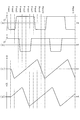
- FIG. 8 is an example of a timing chart of voltages generated by the power supply unit 10 at the terminals T1, T2, T3, and T4.
- the power supply unit 10 generates a voltage of ⁇ 1.0 V between Phase 1 and Phase 2 at the first terminal T1, and 5 Phases of Phase 3 to Phase 7 generate a voltage of 1.0 V, and Phase 8 to Phase 10
- the 3 Phase generates a voltage of -1.0V.
- 5 phases of 1.0V voltage and 3 phases of ⁇ 1.0V voltage are repeated. That is, the power supply unit 10 generates a voltage having 8 Phase as one cycle at the first terminal.
- the power supply unit 10 causes the second terminal T2 to generate a voltage having a phase difference of 180 ° from the voltage generated at the first terminal T1 and having the same 8 Phase as the voltage generated at the first terminal T1 as one cycle. . That is, the voltage generated at the first terminal and the voltage generated at the second terminal have a phase difference of 4 Phases corresponding to a half cycle.
- the power supply unit 10 maintains the voltage generated at the third terminal T3 in Phase 1 at 0 V, generates a voltage of ⁇ 3.0 V in Phase 2, and increases the voltage by 1.0 V in each phase from Phase 3 to Phase 8. In subsequent phases, the voltage generation pattern of Phase 1 to Phase 8 is repeated. That is, the power supply unit 10 generates a voltage having 8 Phase as one cycle at the third terminal T3.
- the power supply unit 10 causes the fourth terminal T4 to generate a voltage having a phase difference of 180 ° from the voltage to be generated at the third terminal T3 and having the same 8 Phase as the voltage to be generated at the third terminal T3. . That is, the voltage generated at the third terminal and the voltage generated at the fourth terminal have a phase difference of 4 Phase corresponding to a half cycle.
- the frequency of the voltage supplied from the power supply unit 10 to the first piezoelectric element 6 and the second piezoelectric element 7 includes the first piezoelectric element 6, the second piezoelectric element 7, the driving piece 3, and the base part 2. It is substantially equal to the frequency of the resonance vibration of the support drive part (structure part) 1a.
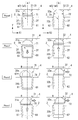
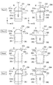
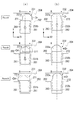
- FIGS. 9 to 11 are enlarged front views showing the operation of the first and second sets of drive pieces 31 and 32 and the operation of the rotor 4.
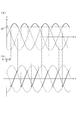
- FIG. 12 is a graph showing the relationship between the displacement in the axial direction of the tip portions 31a and 32a of the first and second sets of drive pieces 31 and 32 and time t. 12A and 12B, the contact position y1 with the rotor 4 in the Y-axis direction is represented by a broken line.
- the width w31 direction (first direction) of the first set of drive pieces 31 along the rotational direction R (see FIG. 4) of the rotor 4 is the X1 direction
- the support shaft 5 Description will be made using an orthogonal coordinate system in which the direction (second direction) parallel to (see FIG. 2) is the Y direction.
- 9 (b) to 11 (b) the width w32 direction (first direction) of the second set of drive pieces 32 along the rotation direction R of the rotor 4 is the X2 direction and the direction parallel to the support shaft 5 ( The description will be made using an orthogonal coordinate system in which the second direction is the Y direction.
- Phase 0 the power supply unit 10 does not generate voltage (0V) at each terminal T1, T2, T3, T4 in Phase 0, and the first piezoelectric element 6 and the second piezoelectric element shown in FIGS. 7A and 7B.
- This is a state in which a voltage of 0 V is supplied to the element 7 (no voltage is supplied).
- the first set of drive pieces 31 and the second set of drive pieces 32 have the top surfaces of the tip portions 31a and 32a in contact with the rotor 4, respectively. Still in a state.
- the rotor 4 is stationary while being supported by the tip portions 31a, 32a of the drive pieces 31, 32.
- Phase 1 As shown in FIG. 8, the power supply section 10 generates a voltage of ⁇ 1.0 V at the first terminal T1 in Phase 1, and the electrode section of the first piezoelectric element 61 of the first set of driving pieces 31 shown in FIG. 7A. A voltage is supplied to 61 a via the first wiring 11. Further, as shown in FIG. 8, the power supply unit 10 maintains the voltage of the third terminal T3 at 0 V in Phase 1 and connects the third wiring to the second piezoelectric element 71 of the first set of driving pieces 31 shown in FIG. 7B. A voltage of 0 V is supplied via 13.
- the first piezoelectric element 61 that drives the first set of drive pieces 31 undergoes thickness-slip deformation, and the base 31b of the drive piece 31 becomes the support surface 2f of the holding portion 2a.
- the Y-direction base part 2 side (Y-axis negative direction side) is moved (see FIG. 12A, Phase 1).
- the second piezoelectric element 71 is not deformed, and the tip 31a does not move in the X1 direction (see FIG. 12C, Phase 1).
- the tip 31 a of the drive piece 31 moves to the Y axis negative direction side and is separated from the rotor 4.
- the power supply unit 10 generates a voltage of 1.0 V at the second terminal T2 in Phase 1, and the electrode unit 62a of the first piezoelectric element 62 of the second set of driving pieces 32 shown in FIG. 7A. A voltage is supplied to the first through the second wiring 12. Further, as shown in FIG. 8, the power supply unit 10 maintains the voltage of the fourth terminal T4 at 0 V in Phase 1, and the second piezoelectric element 72 of the second set of driving pieces 32 shown in FIG. A voltage of 0V is supplied through the wiring.
- the first piezoelectric element 62 that drives the second set of drive pieces 32 undergoes thickness-slip deformation, and the base portion 32b of the drive piece 32 becomes the support surface 2f of the holding portion 2a.
- the Y-direction rotor 4 side (Y-axis positive direction side) is moved (see FIG. 12B, Phase 1).
- the second piezoelectric element 72 is not deformed, and the tip 32a does not move in the X2 direction (see FIG. 12D, Phase 1).
- the drive piece 32 moves to the Y-axis positive direction side, and the front-end
- the tip end portion 31 a of the first set of driving pieces 31 moves to the Y axis negative direction side and is separated from the rotor 4.
- the tip end portion 32 a of the second set of driving pieces 32 pushes the rotor 4 up to the Y axis positive direction side while abutting the rotor 4 and supporting the rotor 4.
- Phase 2 As shown in FIG. 8, the power supply unit 10 maintains the voltage of the first terminal T1 at ⁇ 1.0 V in Phase 2, and the electrode unit of the first piezoelectric element 61 of the first set of driving pieces 31 shown in FIG. 7A. The voltage supplied to the 61a through the first wiring 11 is maintained. Further, as shown in FIG. 8, the power supply unit 10 generates a voltage of ⁇ 3.0 V at the third terminal T3 in Phase 2 and applies it to the second piezoelectric element 71 of the first set of driving pieces 31 shown in FIG. 7B. A voltage is supplied through the third wiring 13.
- the deformation of the first piezoelectric element 61 that drives the first set of driving pieces 31 in the Y direction is maintained, and the tip 31a is separated from the rotor 4 Is maintained (see FIG. 12A, Phase 2).
- the second piezoelectric element 71 undergoes thickness-slip deformation, and the tip portion 31a moves to the X1 axis negative direction side with respect to the base portion 31b and the base portion 2 ( (Refer FIG.12 (c)).
- the amount of movement of the tip 31a at this time is proportional to the absolute value of the voltage supplied to the second piezoelectric element 71.
- the power supply unit 10 maintains the voltage of the second terminal T2 at 1.0 V in Phase 2, and the electrode unit 62a of the first piezoelectric element 62 of the second set of drive pieces 32 shown in FIG. 7A.
- the voltage supplied through the second wiring 12 is maintained.
- the power supply unit 10 generates a voltage of 1.0 V at the fourth terminal T4 in Phase 2, and the second piezoelectric element 72 of the second set of driving pieces 32 shown in FIG. A voltage is supplied through the four wirings 14.
- the deformation of the first piezoelectric element 62 that drives the second set of driving pieces 32 in the Y direction is maintained, and the tip 32a is in contact with the rotor 4 Is maintained (see FIG. 12B, Phase 2).
- the second piezoelectric element 72 undergoes thickness-slip deformation, and the distal end portion 32a moves to the X2 axis positive direction side with respect to the base portion 32b and the base portion 2 ( (Refer FIG.12 (d) and Phase2).
- the amount of movement of the tip portion 32a is proportional to the absolute value of the voltage, and thus is smaller than the amount of movement of the first set of tip portions 31a in the negative direction of the X1 axis.
- the power supply unit 10 generates a voltage of 1.0 V with positive and negative reversed at the first terminal T ⁇ b> 1 in Phase 3, and the first piezoelectric element 61 of the first set of driving pieces 31 shown in FIG. 7A. A voltage is supplied to the electrode portion 61 a through the first wiring 11. Further, as shown in FIG. 8, the power supply unit 10 generates a voltage of ⁇ 2.0 V at the third terminal T3 in Phase 3, and applies it to the second piezoelectric element 71 of the first set of driving pieces 31 shown in FIG. 7B. A voltage is supplied through the third wiring 13.
- the first piezoelectric element 61 that drives the first set of drive pieces 31 undergoes thickness-slip deformation in the reverse direction, and the base 31b of the drive piece 31 is moved in the Y-axis positive direction. (See FIG. 12A, Phase 3).
- the amount of deformation of the second piezoelectric element 71 in the negative direction of the X1 axis decreases, and the tip 31a is positive with respect to the base 31b and the base 2 in the X1 direction. It moves to the direction side (see FIG. 12C, Phase 3).
- the amount of movement at this time is proportional to the difference in voltage between ⁇ 2.0 V newly supplied in Phase 3 and ⁇ 3.0 V supplied in Phase 2.
- the power supply unit 10 maintains the voltage of the second terminal T2 in Phase 3, and the second wiring is connected to the electrode unit 62a of the first piezoelectric element 62 of the second set of driving pieces 32 shown in FIG. 7A.
- the voltage supplied through 12 is maintained.
- the power supply unit 10 generates a voltage of 2.0 V at the fourth terminal T4 in Phase 3, and the second piezoelectric element 72 of the second set of driving pieces 32 shown in FIG. A voltage is supplied through the four wirings 14.
- the tip end portion 31a of the first set of driving pieces 31 moves in the Y-axis positive direction while moving toward the X1-axis positive direction along the rotation direction R of the rotor 4. Move to the side and approach the rotor 4 and come into contact therewith.
- the distal end portion 32 a of the second set of driving pieces 32 abuts against the rotor 4 and supports the rotor 4 while driving the rotor 4 in the rotational direction R.
- Phase 4 As shown in FIG. 8, the power supply unit 10 maintains the voltage of the first terminal T1 at 1.0 V in Phase 4, and the electrode unit 61a of the first piezoelectric element 61 of the first set of driving pieces 31 shown in FIG. 7A. The voltage supplied through the first wiring 11 is maintained. Further, as shown in FIG. 8, the power supply unit 10 generates a voltage of ⁇ 1.0 V at the third terminal T3 in Phase 4, and applies it to the second piezoelectric element 71 of the first set of driving pieces 31 shown in FIG. 7B. A voltage is supplied through the third wiring 13.
- the power supply unit 10 generates a voltage of ⁇ 1.0 V with positive and negative reversed at the second terminal T2 in Phase 4, and the first piezoelectric element of the second set of driving pieces 32 shown in FIG. 7A. A voltage is supplied to the electrode part 62 a of 62 through the second wiring 12. Further, as shown in FIG. 8, the power supply unit 10 generates a voltage of 3.0 V at the fourth terminal T4 in Phase 4, and the second piezoelectric element 72 of the second set of driving pieces 32 shown in FIG. A voltage is supplied through the four wirings 14.
- the first piezoelectric element 62 that drives the second set of driving pieces 32 undergoes thickness-slip deformation in the reverse direction, and the base 32b of the driving piece 32 is moved in the negative direction of the Y-axis. (See FIG. 12 (b), Phase 4).
- the amount of deformation of the second piezoelectric element 72 in the positive direction of the X2 axis increases, and the tip 32a is positive in the X2 axis with respect to the base 32b and the base 2. It moves to the direction side (see FIG. 12D, Phase 4).
- the amount of movement at this time is proportional to the absolute value of the difference in voltage between 3.0 V newly supplied in Phase 4 and 2.0 V supplied in Phase 2.
- the tip end portion 31a of the first set of drive pieces 31 is in the X1-axis positive direction side along the rotational direction R of the rotor 4 in contact with the rotor 4.
- the rotor 4 is supported and driven in the rotation direction R.
- the tip 32a of the second set of driving pieces 32 moves to the Y2 negative direction side while moving to the X2 axis positive direction side along the rotation direction R of the rotor 4. And away from the rotor 4.
- the rotor 4 is driven in the rotation direction R by the tip portions 31a and 32a of the first set and the second set of drive pieces 31, 32, and the first set of drive pieces 32 is driven from the tip portion 32a of the second set of drive pieces 32.
- the rotor 4 is delivered to the tip 31a of the drive piece 31.
- both the drive pieces 31, 32 may be separated from the rotor 4 for a very short time. Even in such a case, the rotor 4 stays at the position supported by the distal end portion 32a of the second set of drive pieces 32 with almost no displacement in the Y direction due to its inertia. Therefore, the rotor 4 is supported in the Y direction by the tip end portion 31a of the first set of driving pieces 31 and is driven in the rotational direction R while being maintained in a substantially constant position in the Y direction and driven in the rotational direction R. Is done. As a result, the rotor 4 continues to rotate around the support shaft 5 at a substantially constant position in the Y direction.
- Phase 5 the power supply unit 10 maintains the voltage of the first terminal T1 at 1.0 V in Phase 5, and the electrode unit 61a of the first piezoelectric element 61 of the first set of driving pieces 31 shown in FIG. 7A. The voltage supplied through the first wiring 11 is maintained. Further, as shown in FIG. 8, the power supply unit 10 sets the voltage generated at the third terminal T3 to 0 V in Phase 5, and connects the third wiring to the second piezoelectric element 71 of the first set of driving pieces 31 shown in FIG. 7B. The voltage supplied through 13 is set to 0V.
- the power supply unit 10 maintains the voltage of the second terminal T2 at ⁇ 1.0 V in Phase 5, and the electrode part of the first piezoelectric element 62 of the second set of driving pieces 32 shown in FIG. 7A.
- the voltage supplied to 62a through the second wiring 12 is maintained.
- the power supply unit 10 sets the voltage generated at the fourth terminal T4 to 0 V in Phase 5, and connects the fourth wiring to the second piezoelectric element 72 of the second set of driving pieces 32 shown in FIG. 7B.
- the voltage supplied through 14 is set to 0V.
- the tip end portion 31a of the first set of driving pieces 31 maintains the state in contact with the rotor 4 and supports the rotor 4, while maintaining the X1-axis positive direction.
- the rotor 4 is driven in the rotation direction R by moving to the direction side.
- the tip 32a of the second set of drive pieces 32 moves to the Y axis negative direction side and is kept away from the rotor 4, while maintaining the base portion 32b and the base portion. 2 to the X2 axis negative direction opposite to the rotation direction R of the rotor 4.
- Phase 6 the power supply unit 10 maintains the voltage of the first terminal T1 at 1.0 V in Phase 6, and the electrode unit 61a of the first piezoelectric element 61 of the first set of driving pieces 31 shown in FIG. 7A. The voltage supplied through the first wiring 11 is maintained. Further, as shown in FIG. 8, the power supply unit 10 generates a voltage of 1.0 V at the third terminal T ⁇ b> 3 in Phase 6, and the second piezoelectric element 71 of the first set of driving pieces 31 shown in FIG. A voltage is supplied through the three wirings 13.
- Phase 6 the deformation of the first piezoelectric element 61 that drives the first set of driving pieces 31 in the Y direction is maintained, and the tip 31a is in contact with the rotor 4 Is maintained (see FIG. 12A, Phase 6).
- the second piezoelectric element 71 undergoes thickness-slip deformation, and the tip portion 31a moves to the X1-axis positive direction side with respect to the base portion 31b and the base portion 2 ( (Refer FIG.12 (c) and Phase6).
- the amount of movement at this time is proportional to the absolute value of the voltage newly supplied in Phase 6.
- the power supply unit 10 maintains the voltage of the second terminal T2 at ⁇ 1.0 V in Phase 6, and the electrode part of the first piezoelectric element 62 of the second set of driving pieces 32 shown in FIG. 7A.
- the voltage supplied to 62a through the second wiring 12 is maintained.
- the power supply unit 10 generates a voltage of ⁇ 3.0 V at the fourth terminal T4 in Phase 6 and applies it to the second piezoelectric element 72 of the second set of driving pieces 32 shown in FIG. 7B.
- a voltage is supplied through the fourth wiring 14.
- the deformation of the first piezoelectric element 62 that drives the second set of driving pieces 32 in the Y direction is maintained, and the tip 32a is separated from the rotor 4. Is maintained (see FIG. 12B, Phase 6).
- the second piezoelectric element 72 undergoes thickness-slip deformation, and the distal end portion 32a moves to the X2 axis negative direction side with respect to the base portion 32b and the base portion 2 ( (Refer FIG.12 (d) and Phase6).
- the amount of movement of the tip 32a at this time is proportional to the absolute value of the voltage supplied to the second piezoelectric element 72.
- the tip end portion 31a of the first set of driving pieces 31 maintains the state in contact with the rotor 4 and supports the rotor 4, while maintaining the X1-axis positive direction.
- the rotor 4 is driven in the rotational direction R by moving in the direction side.
- the distal end portion 32 a of the second set of driving pieces 32 is kept away from the rotor 4, and the rotational direction of the rotor 4 with respect to the base portion 32 b and the base portion 2. It further moves to the X2 axis negative direction side opposite to R.
- Phase 7 As shown in FIG. 8, the power supply unit 10 maintains the voltage of the first terminal T1 at 1.0 V in Phase 7, and the electrode unit 61a of the first piezoelectric element 61 of the first set of drive pieces 31 shown in FIG. 7A. The voltage supplied through the first wiring 11 is maintained. Further, as shown in FIG. 8, the power supply unit 10 generates a voltage of 2.0 V at the third terminal T3 in Phase 7, and the second piezoelectric element 71 of the first set of driving pieces 31 shown in FIG. A voltage is supplied through the three wirings 13.
- the power supply unit 10 generates a voltage of 1.0 V in which the positive and negative are reversed at the second terminal T2 in Phase 7, and the first piezoelectric element 62 of the second set of driving pieces 32 shown in FIG. 7A. A voltage is supplied to the electrode portion 62 a via the second wiring 12. Further, as shown in FIG. 8, the power supply unit 10 generates a voltage of ⁇ 2.0 V at the fourth terminal T4 in Phase 7 and applies it to the second piezoelectric element 72 of the second set of driving pieces 32 shown in FIG. 7B. A voltage is supplied through the fourth wiring 14.
- the first piezoelectric element 62 that drives the second set of drive pieces 32 undergoes thickness-slip deformation in the reverse direction, and the base 32b of the drive piece 32 is moved in the Y-axis positive direction. (See FIG. 12 (b), Phase 7).
- the amount of deformation of the second piezoelectric element 72 in the negative direction of the X2 axis decreases, and the tip 32a is positive in the X2 axis relative to the base 32b and the base 2. It moves to the direction side (see FIG. 12 (d), Phase 7).
- the amount of movement at this time is proportional to the absolute value of the voltage difference between ⁇ 2.0 V newly supplied in Phase 7 and ⁇ 3.0 V supplied in Phase 6.
- the tip 31 a of the first set of drive pieces 31 maintains the state in contact with the rotor 4 while supporting the rotor 4. Drive in the direction of rotation R.
- the tip 32 a of the second set of drive pieces 32 moves to the Y-axis positive direction while moving to the X2-axis positive direction along the rotation direction R of the rotor 4. Then, the rotor 4 approaches and comes into contact.
- the power supply unit 10 generates a voltage of ⁇ 1.0 V with positive and negative reversed at the first terminal T1 in Phase 8, and the first piezoelectric element of the first set of driving pieces 31 shown in FIG. 7A. A voltage is supplied to the electrode portion 61 a of 61 through the first wiring 11. Further, as shown in FIG. 8, the power supply unit 10 generates a voltage of 3.0 V at the third terminal T3 in Phase 8, and the second piezoelectric element 71 of the first set of driving pieces 31 shown in FIG. A voltage is supplied through the three wirings 13.
- the first piezoelectric element 61 that drives the first set of drive pieces 31 undergoes thickness-slip deformation in the reverse direction, and the base 3b of the drive piece 3 is moved in the negative Y-axis direction.
- the amount of deformation of the second piezoelectric element 71 in the X1-axis positive direction increases, and the tip 31a is positive in the X1-axis relative to the base 31b and the base 2. It moves to the direction side (see FIG. 12C, Phase 8).
- the amount of movement at this time is proportional to the absolute value of the difference in voltage between 3.0 V newly supplied in Phase 8 and 2.0 V supplied in Phase 7.
- the power supply unit 10 maintains the voltage at the second terminal T2 at 1.0 V in Phase 8, and the electrode unit 62a of the first piezoelectric element 62 of the second set of drive pieces 32 shown in FIG. 7A.
- the voltage supplied through the second wiring 12 is maintained.
- the power supply unit 10 generates a voltage of ⁇ 1.0 V at the fourth terminal T4 in Phase 8, and applies it to the second piezoelectric element 72 of the second set of driving pieces 32 shown in FIG. 7B.
- a voltage is supplied through the fourth wiring 14.
- the tip end portion 31a of the first set of driving pieces 31 moves to the X1-axis positive direction side along the rotation direction R of the rotor 4, while the Y-axis negative It moves in the direction and moves away from the rotor 4.
- the tip end portion 32 a of the second set of drive pieces 32 moves to the X2 axis positive direction side along the rotational direction R of the rotor 4 while being in contact with the rotor 4.
- the rotor 4 is supported and driven in the rotation direction R.
- the rotor 4 is driven in the rotation direction R by the tip portions 31a and 32a of the first set and the second set of drive pieces 31 and 32, while the second set is driven from the tip portion 31a of the first set of drive pieces 31.
- the rotor 4 is delivered to the tip 32a of the drive piece 32.
- both drive pieces 31, 32 may be separated from the rotor 4 for a very short time. Even in such a case, the rotor 4 stays at the position supported by the distal end portion 31a of the first set of driving pieces 31 with almost no displacement in the Y direction due to its inertia. Therefore, the rotor 4 is supported in the Y direction by the tip 32a of the second set of driving pieces 32 in a state where the rotor 4 is maintained in a substantially constant position in the Y direction and driven in the rotational direction R, and is driven in the rotational direction R. Is done. As a result, the rotor 4 continues to rotate around the support shaft 5 at a substantially constant position in the Y direction.
- Phase 9 As shown in FIG. 8, the power supply unit 10 maintains the voltage of the first terminal T1 at ⁇ 1.0 V in Phase 9, and the electrode part of the first piezoelectric element 61 of the first set of driving pieces 31 shown in FIG. 7A. The voltage supplied to the 61a through the first wiring 11 is maintained. Further, as shown in FIG. 8, the power supply unit 10 sets the voltage generated at the third terminal T3 to 0 V in Phase 9, and connects the third wiring to the second piezoelectric element 71 of the first set of driving pieces 31 shown in FIG. 7B. The voltage supplied through 13 is set to 0V.
- the power supply unit 10 maintains the voltage of the second terminal T2 at 1.0 V in Phase 9, and the electrode unit 62a of the first piezoelectric element 62 of the second set of drive pieces 32 shown in FIG. 7A.
- the voltage supplied through the second wiring 12 is maintained.
- the power supply unit 10 sets the voltage generated at the fourth terminal T4 to 0 V in Phase 9, and connects the fourth wiring to the second piezoelectric element 72 of the second set of driving pieces 32 shown in FIG. 7B.
- the voltage supplied through 14 is set to 0V.
- the tip 31a of the first set of driving pieces 31 moves in the Y-axis negative direction side and maintains a state separated from the rotor 4, while maintaining the rotor 4 moves in the negative direction of the X1 axis opposite to the rotational direction R.
- the distal end portion 32 a of the second set of driving pieces 32 maintains the state in contact with the rotor 4 while supporting the rotor 4, while rotating in the rotational direction R of the rotor 4.
- the rotor 4 is driven in the rotational direction R by moving along the positive X1 axis direction.
- Phase 10 As shown in FIG. 8, the power supply unit 10 maintains the voltage of the first terminal T1 at ⁇ 1.0 V in Phase 10, and the electrode unit of the first piezoelectric element 61 of the first set of driving pieces 31 shown in FIG. 7A. The voltage supplied to the 61a through the first wiring 11 is maintained. Further, as shown in FIG. 8, the power supply unit 10 generates a voltage of ⁇ 3.0 V at the third terminal T3 in the Phase 10, and causes the second piezoelectric element 71 of the first set of driving pieces 31 shown in FIG. A voltage is supplied through the third wiring 13.
- the deformation of the first piezoelectric element 61 that drives the first set of driving pieces 31 in the Y direction is maintained, and the tip portion 31a is separated from the rotor 4 Is maintained (see FIG. 12A, Phase 10).
- the second piezoelectric element 71 undergoes thickness-slip deformation, and the tip portion 31a moves to the X1 axis negative direction side with respect to the base portion 31b and the base portion 2 ( (Refer FIG.12 (c) and Phase10).
- the amount of movement of the tip 31a at this time is proportional to the absolute value of the voltage supplied to the second piezoelectric element 71.
- the power supply unit 10 maintains the voltage of the second terminal T2 at 1.0 V in Phase 10, and the electrode unit 62a of the first piezoelectric element 62 of the second set of drive pieces 32 shown in FIG. 7A.
- the voltage supplied through the second wiring 12 is maintained.
- the power supply unit 10 generates a voltage of 1.0 V at the fourth terminal T4 in Phase 10, and the second piezoelectric element 72 of the second set of drive pieces 32 shown in FIG. A voltage is supplied through the four wirings 14.
- the deformation of the first piezoelectric element 62 that drives the second set of drive pieces 32 in the Y direction is maintained, and the tip 32a is in contact with the rotor 4 Is maintained (see FIG. 12B, Phase 10).
- the second piezoelectric element 72 undergoes thickness-slip deformation, and the distal end portion 32a moves to the X2-axis positive direction side with respect to the base portion 32b and the base portion 2 ( (Refer FIG.12 (d) and Phase10).
- the amount of movement at this time is proportional to the absolute value of the voltage newly supplied in Phase 10.
- the distal end portion 31a of the first set of driving pieces 31 is X1 with respect to the base portion 31b and the base portion 2 while maintaining a state of being separated from the rotor 4. Move further to the negative side of the shaft.
- the distal end portion 32 a of the second set of driving pieces 32 maintains the state in contact with the rotor 4 while supporting the rotor 4, while rotating in the rotational direction R of the rotor 4.
- the rotor 4 is driven in the rotational direction R by moving along the X2 axis positive direction.
- the first piezoelectric element 6 that drives each driving piece 3 in the direction parallel to the support shaft 5 (second direction) and the tip 3 a of the driving piece 3 are rotated by the rotor 4.
- a second piezoelectric element 7 that is driven in the width w3 direction (first direction) of the drive piece 3 along the direction R is provided separately and independently. Therefore, vibrations in the respective directions can be extracted as independent vibrations.
- the rotor 4 when the rotor 4 is rotated by the driving piece 3 and the rotor 4 and the driving piece 3 are relatively driven, the rotor 4 can be rotated more stably than in the prior art. Further, compared to the case where the first piezoelectric element 6 sandwiching the base 3b drives the base 3b in different directions, loss is less likely to be generated, energy efficiency can be improved, and the output of the driving device 1 is increased. Can do.
- the electrode portion 6 a of the first piezoelectric element 6 has an exposed portion 6 b exposed from the base portion 2. Therefore, when the first piezoelectric element 6 having the electrode portion 6a is assembled to the base portion 2, it is possible to prevent the electrode portion 6a from being covered with the base portion 2 and making electrical connection difficult. As a result, the drive device 1 can be assembled easily and reliably, and productivity and yield can be improved.
- the electrode portion 6a is formed in a normal rectangular shape, and the portion exposed from the base portion 2 is the exposed portion 6b. That is, it is not necessary to form the electrode part 6a in a special shape. Further, the electrode portion 6 a of the first piezoelectric element 6 is provided integrally with the first piezoelectric element 6. For this reason, compared with the case where the electrode part 6a and the 1st piezoelectric element 6 are provided separately and each assembled
- the electrode portion 6a of the first piezoelectric element 6 is provided on the surface facing the support surface 2f of the holding portion 2a of the base portion 2. Therefore, the exposed portion 6b that is a part of the electrode portion 6a can be exposed from the base portion 2.
- a chamfered portion 2 h is provided as an exposure forming portion for exposing the exposed portion 6 b of the electrode portion 6 a to the base portion 2. Therefore, even if an error occurs during assembly, the exposed portion 6 b can be reliably exposed from the base portion 2.
- the chamfered portion 2h is provided at a corner of the end portion of the base portion 2 on the rotor 4 side. Therefore, for example, when a concave notch or a meat stealer is provided on the end surface between the outer peripheral corner and the inner peripheral corner, or a concave notch or meat is formed on a part of the support surface 2f of the holding portion 2a.
- the rigidity of the base part 2 and the holding part 2a can be increased as compared with the case of providing theft. As a result, it is possible to extract vibrations in the width w3 direction (first direction) of the driving piece 3 and vibrations in the direction parallel to the support shaft 5 (second direction) more independently.
- the manufacturing process can be prevented from becoming complicated, the number of manufacturing processes can be prevented from increasing, and the productivity can be prevented from decreasing.
- the exposed part 6b and the power supply part 10 are electrically connected, the voltage generated in the power supply part 10 can be applied to the electrode part 6a via the exposed part 6b. Further, the first piezoelectric element 6 can be driven by applying a voltage between the electrode portion 6 a and the base portion of the driving piece 3.
- the first piezoelectric element 6 sandwiches the base 3b of the driving piece 3 from the width w3 direction, and the first piezoelectric element 6 drives the driving piece 3 in a direction parallel to the support shaft 5 different from the width w3 direction.
- the size and shape of the pair of first piezoelectric elements 6 and 6 sandwiching the base portion 3b are substantially equal. Thereby, the rigidity of the drive piece 3 in the width w3 direction can be made uniform. Therefore, vibration in the width w3 direction of the base 3b of the drive piece 3 can be suppressed.
- all the first piezoelectric elements 6 and the second piezoelectric elements 7 have the same shape and size, manufacturing can be facilitated and productivity can be improved.
- the base portion 2 is provided with a holding portion 2 a that holds the driving piece 3 in a direction parallel to the support shaft 5.
- the holding portion 2a is provided with a support surface 2f that supports the base portion 3b of the drive piece 3 from the width w3 direction of the drive piece 3. Therefore, the first piezoelectric element 6 can be supported by the support surface 2f, and the base 3b of the driving piece 3 can be supported from the width w3 direction via the first piezoelectric element 6. Thereby, the rigidity in the width w3 direction of the drive piece 3 can be further increased, and the vibration in the width w3 direction of the base portion 3b of the drive piece 3 can be suppressed.
- the ratio of the elastic modulus in the thickness direction (longitudinal elastic modulus) and the elastic modulus in the deformation direction (lateral elastic modulus) is about 3: 1, for example. Therefore, the rigidity of the driving piece 3 in the width w3 direction can be increased, and the rigidity of the base portion 3b in the driving direction can be decreased. Thereby, the movement of the base 3b in the width w3 direction can be prevented and vibration can be suppressed. Further, it is possible to facilitate displacement of the base portion 3b in the driving direction.
- the support surface 2f of the holding portion 2a is provided so as to be inclined in a direction parallel to the support shaft 5 of the driving piece 3, and is separated from the rotor 4 to be a bottom surface of the holding portion 2a.
- the width w4 'between the support surfaces 2f, 2f is narrower than the width w5 of the base 3b of the drive piece 3 and the pair of first piezoelectric elements 6 on the rotor 4 side than the bottom surface 2g.
- the drive piece 3 and the first piezoelectric elements 6 and 6 sandwiching the base portion 3b are inserted from the rotor 4 side along the direction parallel to the support shaft 5 to the bottom surface 2g side of the holding portion 2a,
- the base 3b and the first piezoelectric element 6 are sandwiched and supported by the support surface 2f from the width w4 direction.
- the drive piece 3 can be positioned in a direction parallel to the support shaft 5. Further, since the support surface 2f does not restrict the drive of the drive piece 3 to the rotor 4 side, the drive piece 3 can be held to be driven to the rotor 4 side.
- the side surface 3c of the base 3b of the drive piece 3 facing the support surface 2f is inclined and provided substantially parallel to the support surface 2f in the same manner as the support surface 2f. Therefore, when the base 3b of the drive piece 3 and the first piezoelectric elements 6 and 6 sandwiching the base 3b are inserted from the rotor 4 side along the direction parallel to the support shaft 5 to the bottom surface 2g side of the holding portion 2a, The first piezoelectric element 6 can be pressure-bonded to the support surface 2f by bringing the first piezoelectric element 6 and the support surface 2f of the holding portion 2a into contact with each other without a gap. Thereby, the vibration of the base 3b of the drive piece 3 in the width w3 direction can be suppressed.
- the positioning error of the drive piece 3 in the direction parallel to the support shaft 5 is within the allowable error range. It can be stored.
- the inclination angle ⁇ is smaller than 2 °, not only the positioning accuracy is lowered, but also the manufacture becomes difficult.
- the inclination angle ⁇ is larger than 6 °, the driving of the driving piece 3 in the direction parallel to the support shaft 5 is adversely affected.
- positioning accuracy, manufacturability, and driveability can be improved by setting the inclination angle ⁇ to 4 °.
- the bottom surface 3d of the base portion 3b of the driving piece 3 and the bottom surface 2g of the holding portion 2a are the driving directions of the base portion 3b of the driving piece 3. They are separated in a direction parallel to the support shaft 5. Therefore, the drive piece 3 can be driven from the neutral position to the base portion 2 side. Furthermore, in this embodiment, even when the drive piece 3 is driven from the neutral position to the base portion 2 side, the bottom surface 3d of the base portion 3b and the bottom surface 2g of the holding portion 2a are separated from each other.
- the driving piece 3 supports the rotor 4 and drives the tip 3a in the rotation direction R, and the base 3b held by the holding part 2a of the base 2 while being sandwiched between the pair of first piezoelectric elements 6. And. Further, the driving piece 3 has a holding portion 2a along the rotation direction R of the rotor 4 and a second piezoelectric element 7 for driving the driving piece 3 in the width w3 direction between the tip portion 3a and the base portion 3b. I have.
- a tangential frictional force in the rotational direction R acts between the lower surface of the rotor 4 and the tip 3a of the drive piece 3, and the rotor 4 is rotated in the rotational direction R.
- the first piezoelectric element 6 and the second piezoelectric element 7 can be controlled independently.
- the driving in the direction along the support shaft 5 of the tip 3 a of the driving piece 3 and the driving in the direction along the rotation direction R of the rotor 4 can be controlled independently.
- the first piezoelectric element 6 and the second piezoelectric element 7 are simultaneously operated, and the driving in the direction along the support shaft 5 of the tip 3 a of the driving piece 3 and the driving in the direction along the rotation direction R of the rotor 4 are performed simultaneously. It can be carried out. Therefore, as shown in FIGS. 9 to 11, when the rotor 4 and the tip 3a are in contact with and separated from each other, the tip 3a of the drive piece 3 is moved along the rotation direction R of the rotor 4 to rotate the rotor 4. Without interfering, the rotor 4 can be transferred from the first set of drive pieces 31 to the second set of drive pieces 32.
- two sets of driving pieces 3 including three pairs of first piezoelectric elements 6 and 6 sandwiching the driving piece 3 and its base 3b are composed of a first set and a second set. Therefore, each set can be driven at different timings. Further, the rotor 4 can be supported at three points by the tip portions 31a and 32a of the driving pieces 31 and 32 of each set. Accordingly, the rotor 4 can be supported more stably than in the case of two-point support or four-point support or more.
- each set of drive pieces 31 and 32 is equally arranged in the rotation direction R of the rotor 4.
- the first set and the second set of driving pieces 31 and 32 are alternately arranged in the rotation direction R in order. Therefore, the rotor 4 can be supported in a balanced manner by each pair of drive pieces 31 and 32 and can be driven efficiently in the rotation direction R.
- the direction in which the tip 3a of the driving piece 3 is driven is the same as the direction in which the base 3b of the driving piece 3 is sandwiched between the first piezoelectric element 6 and the support surface 2f of the holding portion 2a. Therefore, when the front end portion 3a of the driving piece 3 performs feed driving and return driving, the base portion 3b of the driving piece 3 can be supported from the front and rear in the driving direction. Therefore, it is possible to suppress the drive piece 3 from being displaced from the direction parallel to the support shaft 5 and to prevent the drive of the rotor 4 from being adversely affected.
- the power supply unit 10 can supply the voltages having a phase difference to the first set and the second set of drive pieces 31, 32, so that the rotor 4 can be driven by each set of drive pieces 31, 32. . Further, the power supply unit 10 sets the phase difference of the voltages supplied to the first piezoelectric element 6 and the second piezoelectric element 7 of each set to 180 °, so that the first set of driving pieces 31 and the second set of driving pieces are set. 32 and the rotor 4 can be driven alternately in turn.
- the power supply unit 10 supplies the first piezoelectric element 6 and the second piezoelectric element 7 of each set, the tip 3a of the driving piece 3 contacts the rotor 4, and feeds the driving piece 3 in the width w3 direction.
- the rotation of the rotor 4 can be continuously performed by supplying the voltage so as to sequentially repeat the separation from the center and the return of the drive piece 3 in the width w3 direction.
- the power supply unit 10 overlaps the voltage supplied to the first terminal T1 and the voltage supplied to the second terminal T2. As a result, the rotor 4 can be transferred continuously and smoothly from the first set of drive pieces 31 to the second set of drive pieces 32.
- the power supply unit 10 increases the rate of voltage supplied to the third terminal T3 and the fourth terminal T4 when the tip 3a of the driving piece 3 is driven to feed in the width w3 direction ( (Slope) is different from the voltage reduction rate (slope) during return driving.
- the voltage is increased by 1.0 V in each phase from Phase 2 to Phase 8 for feeding and driving the tip 3a, and the voltage is set to 3 in each Phase from Phase 9 to Phase 10 for returning and driving the tip 3a. It is decreased by 0V.
- the feed drive time of the front end 3a of the drive piece 3 can be made longer than the return drive time, and the contact time between the front end 3a of the drive piece 3 and the rotor 4 can be extended. Therefore, the power of the drive piece 3 can be transmitted to the rotor 4 more efficiently.
- the frequency of the voltage supplied from the power supply unit 10 to the first piezoelectric element 6 and the second piezoelectric element 7 is a support driving unit including the first piezoelectric element 6, the second piezoelectric element 7, the driving piece 3, and the base unit 2. It is substantially equal to the frequency of the resonance vibration of 1a. Therefore, the amplitude of the feed drive and return drive of the rotor 4 by the tip 3a of the drive piece 3 can be further increased.
- the frequency of resonance vibration of the support driving unit 1a can be adjusted by appropriately selecting the material of the base unit 2, the piezoelectric element, the tip 3a and the base 3b of the driving piece 3.
- the period of the voltage supplied from the first terminal T1 and the second terminal T2 to the first piezoelectric elements 61 and 62 of each pair of driving pieces 31, 32, and the first The periods of the voltages supplied from the three terminals T3 and the fourth terminal T4 to each pair of the second piezoelectric elements 71 and 72 are equal. Accordingly, the driving frequency of the driving pieces 31 and 32 in the direction parallel to the support shaft 5 is equal to the driving frequency of the driving pieces 31 and 32 in the widths w31 and w32 directions of the tip portions 31a and 32a.
- the amplitude of the drive pieces 31 and 32 in the direction parallel to the support shaft 5 and the amplitude of the tip portions 31a and 32a in the widths w31 and w32 directions of the drive pieces 31 and 32 can be set to the maximum amplitude.
- the tip 3 a of the drive piece 3 is provided in a tapered shape so that the cross-sectional area along the rotation direction R of the rotor 4 becomes smaller as the rotor 4 approaches. Therefore, compared with the case where the tip 3a is formed in a rectangular parallelepiped shape, the contact area between the tip 3a and the rotor 4 is reduced, and the volume change rate of the tip 3a due to wear of the tip 3a is reduced. Can do. Thereby, the change of the weight of the front-end
- a groove portion 2d is formed on a side surface 2c of the base portion 2 that is provided substantially in parallel with the support shaft 5 and intersects the width w3 direction of the drive piece 3 substantially perpendicularly. That is, the groove 2 d is provided so as to intersect substantially perpendicularly to vibration in a direction substantially parallel to the support shaft 5 propagating through the base 2. Therefore, the vibration can be absorbed by the groove 2d and the propagation of vibration by the base 2 can be reduced.
- the first piezoelectric element 6 is provided between the rotor 4 and the groove 2d. Therefore, vibration propagating beyond the groove 2d from the opposite side of the base 2 to the rotor 4 can be reduced.
- the end of the base portion 2 opposite to the holding portion 2a that holds the drive piece 3 is fixed to the attachment portion 101a, and the groove portion 2d is provided at a position closer to the attachment portion 101a than the drive piece 3. Therefore, even when the vibration of the mounting portion 101 a propagates to the base portion 2, the vibration is reduced at a position relatively far from the driving piece 3, and the vibration of the mounting portion 101 a adversely affects the driving of the driving piece 3. Can be prevented.
- the width w1 of the groove portion 2d in the direction parallel to the support shaft 5 is larger than the amplitude of vibration of the base portion 2. Therefore, it is possible to prevent the base portions 2 on both sides of the groove portion 2d from colliding with each other.
- the width w1 of the groove 2d in the direction parallel to the support shaft 5 is larger than the amplitude of the resonance vibration of the support drive unit 1a including the base unit 2, the drive piece 3, the first piezoelectric element 6, and the second piezoelectric element 7. It is getting bigger. Therefore, even when the support drive part 1a vibrates in a resonance state, it is possible to prevent the base parts 2 on both sides of the groove part 2d from colliding with each other.
- the depth d1 of the groove 2d is set to be 40% or more and 80% or less of the radius of the base part 2, it is possible to obtain a sufficient suppression effect of vibration propagation while ensuring sufficient strength of the base part 2. it can.
- the gap 2e is formed between the base portion 2 and the support shaft 5, vibration propagating from the base portion 2 to the support shaft 5 can be reduced. Further, vibration propagating from the support shaft 5 to the base portion 2 can be reduced. Therefore, it is possible to prevent the drive piece 3 and the rotor 4 from being adversely affected.
- the interchangeable lens of this embodiment forms a camera system with a camera body.
- the interchangeable lens can be switched between an AF mode for performing a focusing operation according to a known AF (autofocus) control and an MF (manual focus) mode for performing a focusing operation according to a manual input from a photographer. ing.
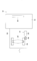
- FIG. 13 is a schematic configuration diagram schematically illustrating the configuration of the camera 101 in the present embodiment.
- the camera 101 includes a camera body 102 in which an image sensor 108 is built, and a lens barrel 103 having a lens 107.
- the lens barrel 103 is an interchangeable lens that can be attached to and detached from the camera body 102.
- the lens barrel 103 includes a lens 107, a cam barrel 106, the driving device 1, and the like.
- the driving device 1 is used as a driving source that drives the lens 107 during the focusing operation of the camera 101.
- the driving force obtained from the rotor 4 of the driving device 1 is directly transmitted to the cam cylinder 106.
- the lens 107 is a focus lens that is held by the cam cylinder 106 and moves in substantially parallel to the optical axis direction L by the driving force of the driving device 1 to perform focus adjustment.
- a subject image is formed on the imaging surface of the imaging element 108 by a lens group (including the lens 107) provided in the lens barrel 103.
- the imaged subject image is converted into an electrical signal by the image sensor 108.
- Image data is obtained by A / D converting the signal.
- the camera 101 and the lens barrel 103 of the present embodiment include the driving device 1 described in the above embodiment. Therefore, the rotor 4 can be rotated more stably than in the prior art, and the cam cylinder 106 can be directly driven by the drive device 1 with improved output. Therefore, there is little energy loss and an energy saving effect can be obtained. In addition, the number of parts can be reduced.
- the lens barrel 103 is an interchangeable lens.
- the present invention is not limited to this.
- the lens barrel 103 may be a lens barrel integrated with the camera body.
- the aspect of this invention is not restricted only to embodiment mentioned above, A various deformation
- the electrode portion of the first piezoelectric element may not be provided integrally with the first piezoelectric element. That is, the electrode unit and the first piezoelectric element may be separated from each other, and the electrode unit and the first piezoelectric element may be joined when the driving piece is held by the holding unit.
- the electrode part may have an ear piece-like (tab-shaped) exposed part exposed from the base part by protruding from the base part.
- the dimensions of the first piezoelectric element, the dimensions of the electrode portion, and their attachment positions are preliminarily determined by the electrode portion. Adjustment may be made so as to protrude from the end of the base portion on the rotor side or the side surface of the base portion, and the exposed portion of the electrode portion protruding from the base portion may be used as the exposed portion.
- the exposure forming part that exposes the exposed part of the electrode part is not limited to the chamfered part described in the above embodiment.
- a chamfered portion, a notch portion, or a meat stealing portion is provided only at the corner portions on both sides of the holding portion.
- the exposed portion may be exposed.
- a groove-like chamfered portion, a cutout portion or a meat stealing portion is provided between the outer peripheral corner portion and the inner peripheral corner portion. Also good.
- the exposed portion may be exposed by providing a chamfered portion, a notch portion, or a meat stealing portion on the side surface of the base portion between the end portion on the rotor side of the base portion and the bottom surface of the holding portion.
- the conductive adhesive is used as the conductive material for conducting the exposed portion of the electrode portion and the electrode surface.
- the conductive material is not limited to the conductive adhesive.
- conductive paste for example, conductive paste, solder, brazing material and the like can be used.
- the case where the first piezoelectric element and the second piezoelectric element are subjected to thickness sliding deformation has been described, but these may be deformed in the thickness direction.
- the driving piece is moved in the width direction (first direction) of the holding portion by the first piezoelectric element, and the tip end portion of the driving piece is moved in the direction parallel to the rotation axis (second direction) by the second piezoelectric element. To do.
- the base part may be divided into a plurality of parts as long as it is provided so as to surround the support shaft, and may not completely surround the support shaft.
- the base portion may be disposed so as to be half of the circumference surrounding the support shaft, or may be disposed so as to sandwich the support shaft from both sides.
- the first piezoelectric element is one of the driving pieces. It may be provided only on the side surface. Further, a piezoelectric element that is displaced in the thickness direction may be used as the first piezoelectric element, and the first piezoelectric element may be disposed between the bottom surface of the holding portion of the base portion and the bottom surface of the base portion of the driving piece.
- the base portion is directly supported from both sides in the width direction of the holding portion along the rotation direction of the rotor by the support surface of the holding portion provided in the base portion without passing through the piezoelectric element. And you may make it function a support surface as a guide part which hold
- the number of driving pieces may be three or more.
- the number of drive pieces provided in the set of drive pieces may be one, two, or four or more.
- two sets of driving pieces may be configured with two sets of driving pieces arranged diagonally of the base portion as one set.
- the phase difference between the voltages of each group can be set to 120 degrees, for example.
- the voltage phase difference of each set of driving pieces may be a value obtained by dividing 360 degrees by the number of sets (that is, 180 degrees for two sets and 120 degrees for three sets).
- the direction in which the first piezoelectric element sandwiches the base of the driving piece (first direction) and the direction in which the second piezoelectric element drives the tip of the driving piece (third direction) are the same. However, they may be different.
- the rotor may be easily rotated by setting the third direction to be a direction that intersects the width w3 direction of the drive piece and is along the rotation direction of the rotor.
- the support surface of the base portion may not be inclined with respect to a direction (second direction) parallel to the support shaft.
- a protrusion-like locking portion that locks the bottom end of the holding portion of the first piezoelectric element may be provided in the holding portion.
- the end portion on the bottom surface side of the holding portion of the first piezoelectric element protrudes from the bottom surface of the base portion to function as a positioning portion, and positioning is performed by abutting the positioning portion against the bottom surface of the holding portion. You may do.
- the gap between the base portion and the support shaft may be formed up to the edge of the groove portion on the holding portion side from the viewpoint of securing the strength of the base portion.
- the voltage supplied from each terminal of the power supply unit to the first piezoelectric element and the second piezoelectric element may be a sine wave or sine wave voltage waveform.
- the first set and the second set there are two sets of driving pieces, the first set and the second set, and the phase difference between the voltage waveforms of the sine waves generated at the first terminal and the second terminal of the power supply unit is 180 °.
- the phase difference between the voltage waveforms of the sine waves generated at the third terminal and the fourth terminal is 180 ° will be described with reference to FIG.
- FIG. 15 (a) shows the displacement in the Y direction of the tip of the first set of driving pieces.
- FIG. 15B shows the displacement in the Y direction of the second set of driving pieces.
- FIG. 15C shows the displacement of the first set of driving pieces in the X1 direction.
- FIG. 15D shows the second set of displacements in the X2 direction (see FIGS. 9 to 11).
- FIGS. 15A and 15B When the phase difference between the voltage waveforms of the sine waves generated at the first terminal and the second terminal of the power supply unit is 180 °, as shown in FIGS. 15A and 15B, driving is performed in the Y-axis direction.
- the leading ends of the first and second sets of driving pieces draw a sinusoidal locus having a phase difference of 180 °.
- the tip of the first set of driving pieces comes into contact with the rotor when the displacement in the Y-axis direction exceeds the contact position y1 (see FIGS. 9 to 11).
- the tip portions of the second set of driving pieces are also in contact with the rotor.
- the locus of the first set of driving pieces shown in FIG. 15A and the locus of the second set of driving pieces shown in FIG. 15B have a phase difference of 180 °. Therefore, the leading end of the first set of driving pieces and the leading end of the second set of driving pieces alternately contact the rotor to support the rotor (see FIGS. 9 to 11). At this time, as in the above-described embodiment, there is a period in which the tip portions of both drive pieces are separated from the rotor. However, as in the above-described embodiment, the rotor is hardly displaced in the Y direction during that time due to its inertia.
- the tip of the first set of driving pieces is rotated while the rotor is in contact with the rotor (between the thick line portions shown in FIG. 15 (a)). It moves in the X1 axis positive direction along the direction (see FIGS. 9 to 11).
- the tip of the second set of drive pieces is also in contact with the rotor (between the thick line portions shown in FIG. 15 (b)). It moves in the X2 axis positive direction along the rotation direction.
- the rotor is alternately driven in the rotational direction by the first set of drive pieces and the second set of drive pieces (see FIGS. 9 to 11).
- FIG. 16 shows a case in which three sets of driving pieces are configured as first to third sets and a sine wave or a sine wave voltage waveform having a phase difference of 120 ° is generated at each terminal of the power supply unit. It explains using.
- the power supply unit includes a fifth terminal and a sixth terminal for supplying voltages to the first and second piezoelectric elements of the third set of driving pieces, respectively.
- the width direction of the third set of drive pieces that is perpendicular to the support shaft and along the rotational direction of the rotor. Let (the width direction of the holding portion) be the X3 direction.
- FIG. 16A shows the displacement in the Y direction of the tip portions of the first to third drive pieces.
- FIG. 16B shows the displacements in the X1 to X3 directions of the tip portions of the first to third sets of driving pieces.
- 16 (a) and 16 (b) the locus of the tip of the first set of driving pieces is indicated by a solid line, the locus of the tip of the second set of driving pieces is indicated by a broken line, and the locus of the third set of driving pieces is indicated by a one-dot chain line. Show.
- the trajectory of each set of driving pieces shown in FIG. 16 (a) has a phase difference of 120 °. Therefore, the tip portions of the driving pieces of each set contact the rotor in order to support the rotor (see FIGS. 9 to 11). At this time, as in the above-described embodiment, there is a period during which the front ends of the driving pieces of each set are separated from the rotor. However, as in the above-described embodiment, the rotor is hardly displaced in the Y direction during that time due to its inertia.
- each pair of driving pieces is in the rotational direction of the rotor while in contact with the rotor (between the thick line portions shown in FIG. 16A).
- the rotor is sequentially driven in the rotational direction by each set of driving pieces (see FIGS. 9 to 11).
- the driving device 201 performs relative driving in which a second member such as a rotor is relatively displaced with respect to a first member such as a driving piece, for example. It is for driving equipment.
- FIG. 17 is a front view of the drive device 201 of the present embodiment
- FIG. 18 is a sectional view thereof.
- the driving device 201 includes a base portion (base member) 202 provided with a plurality of holding portions 202a, a driving piece (first member) 203 held by the holding portion 202a, A rotor (second member) 204 disposed adjacent to the drive piece 203 and a support shaft 205 inserted through the base portion 202 are provided.
- a gear 204a for driving a lens barrel of a camera is formed on the outer peripheral surface of the rotor 204.
- a supported surface 204 b on the base portion 202 side of the rotor 204 is supported by a plurality of driving pieces 203.
- the rotor 204 is supported by a support shaft 205 via a bearing 204e, and is provided so as to be rotatable about the support shaft 205 as a rotation axis. That is, the support shaft 205 is provided along the rotation axis R ⁇ b> 1 of the rotor 204.
- the base portion 202 is an elastic body having conductivity, and is formed in a hollow cylindrical shape with a metal material such as stainless steel, and is provided so as to surround the support shaft 205 when the support shaft 205 is inserted. .
- One end portion of the base portion 202 is fixed to the attachment portion 301a with, for example, a bolt (not shown).
- a concave portion 202b is formed at the center of the surface of the base portion 202 that faces the mounting portion 301a.
- An enlarged diameter portion 205 a formed at the base end of the support shaft 205 is inserted (inserted) into the recess 202 b. In this state, the base portion 202 is fixed to the attachment portion 301a, so that the support shaft 205 is fixed to the base portion 202 and the attachment portion 301a.
- a plurality of concave holding portions 202a are provided in the circumferential direction of the base portion 202, that is, in the rotation direction R of the rotor 204.
- the holding unit 202a supports the drive piece 203 from both sides in the direction (first direction) perpendicular to the support shaft 205 and along the rotation direction R of the rotor 204 (first direction), and also supports the drive piece 203 in a direction parallel to the support shaft 205 (first direction). 2) is drivable.
- the side surface 202 c of the base portion 202 is provided substantially parallel to the support shaft 205.
- a groove portion 202d is formed as a vibration suppressing portion that suppresses transmission of vibration from the attachment portion 301a to the holding portion 202a. That is, the groove portion 202d is provided on the side surface 202c of the base portion 202 that is substantially perpendicular to the support shaft 205 and intersects the direction along the rotation direction R of the rotor 204 (first direction).
- the groove portion 202d is continuously provided in the circumferential direction of the base portion 202, and is provided at a position closer to the end portion on the attachment portion 301a side than the middle between the holding portion 202a and the end portion on the attachment portion 301a side.
- the depth d201 of the groove 202d is, for example, in the range of 40% to 80% of the radius r201 of the base 202.
- the above numerical value is an example, and the present invention is not limited to this.
- the depth d201 of the groove 202d can be, for example, 10, 20, 30, 40, 50, 60, 70, 80, or 90% of the radius r201 of the base 202.
- the width w201 of the groove 202d in the direction parallel to the support shaft 205 (second direction) is larger than the amplitude of vibration of the base 202, and the first piezoelectric element 206 and the second piezoelectric element (second It is formed so as to be larger than the amplitude of the resonance vibration of the support drive unit (structure unit) 201 a including the piezoelectric element 207, the drive piece 203, and the base unit 202.
- the width w201 of the groove 202d can be shorter than the radius of the base 202.
- a gap (vibration suppressing portion) 202e for suppressing vibration from the mounting portion 301a to the holding portion 202a is provided between the base portion 202 and the support shaft 205.
- the gap 202e is provided in the direction parallel to the support shaft 205 from the end portion on the holding portion 202a side of the base portion 202 to the same position as the edge on the mounting portion 301a side of the groove portion 202d.
- the width w202 of the gap 202e is formed so as to be larger than the amplitude of vibration of the base portion 202 and larger than the amplitude of resonance vibration of the support driving portion 201a described later. .
- An insulating film 202g is formed on the surface of the base portion 202 and subjected to an insulation process.
- the insulating film 202g is formed by applying an insulating material such as acrylic or epoxy on the surface of the base portion 202, for example.
- the insulating film 202g is continuously formed over the side surface of the base portion 202 on the drive piece 203 side, the holding portion 202a, and the surface on the gap 202e side with respect to the groove portion 202d.
- the insulation resistance value of the portion of the base portion 202 where the insulating film 202g is formed is about several M ⁇ as a creeping measurement value.
- the insulating film 202g has a high hardness of, for example, a pencil hardness of 2H or more and has almost no damper component.
- the withstand voltage of the insulating film 202g is desirably about 200 VDC or more, for example.
- the insulating film 202g is formed as thin as possible within the range in which the withstand voltage can be maintained.
- the film thickness is desirably about 10 ⁇ m or more and 20 ⁇ m or less, for example. Further, the variation in film thickness is set to an average film thickness of ⁇ 50% or less, desirably an average film thickness of ⁇ 30% or less.
- the insulating film 202g of this embodiment is made of, for example, an insulating material containing a silica-based composition, has a hardness of 3H or more, a film thickness of about 15 ⁇ m ⁇ 3 ⁇ , and a withstand voltage of about 270 VDC or more.
- FIG. 19 is an enlarged cross-sectional view of the drive piece 203 and the rotor 204 of the holding portion 202a in a cross section parallel to the support shaft 205 and along the rotation direction R of the rotor 204.
- the insulating film 202 g is formed with a uniform film thickness on the entire holding portion 202 a including the supporting surfaces 202 f and 202 f that support the driving piece 203.
- the first piezoelectric element 206 is fixed to the support surface 202f of the holding portion 202a on which the side surface 203c of the driving piece 203 and the insulating film 202g are formed with a conductive adhesive.
- an adhesive for bonding the insulating film 202g and the first piezoelectric element 206 it is desirable to use an adhesive containing a material similar to the insulating film 202g.
- an adhesive containing an acrylic material is used.
- an insulating film 202g containing an epoxy material is used.
- an insulating film 202g is provided between all the first piezoelectric elements 206 and the base portion 202.
- the first piezoelectric element 206 is provided with an electrode 206a on the surface in contact with the insulating film 202g.
- FIG. 20A is a perspective view of the support drive unit 201a of the drive device 201 shown in FIG. 17, and FIG. 20B is a plan view thereof.
- the drive piece 203 has a tip portion 203a having a hexagonal column shape with a mountain-shaped cross section and a base portion 203b having a substantially rectangular parallelepiped shape.
- the tip portion 203a is made of, for example, stainless steel.
- the base 203b is formed of, for example, a light metal alloy or the like, and both have conductivity.
- the base portion 203b is supported by the holding portion 202a so as to be driven in a direction parallel to the support shaft 205, and the distal end portion 203a projects from the holding portion 202a to support the rotor 204.
- the tip portion 203a is provided in a tapered shape in which the area of the upper surface that contacts the rotor 204 is smaller than the area of the bottom surface on the base 203b side.
- first piezoelectric elements 206 and 206 that sandwich the base 203b of the drive piece 203 from both sides in the width w203 direction. Is provided.
- the direction of the width w203 of the drive piece 203 is a direction perpendicular to the support shaft 205 and along the rotation direction R of the rotor 204, and is substantially perpendicular to the center line CL in plan view of the base portion 202.
- the first piezoelectric element 206 is formed in an elongated rectangular shape extending along the direction of the depth d202 of the holding portion 202a, and is sandwiched between the base portion 203b and the holding portion 202a. Accordingly, the first piezoelectric element 206 is disposed between the groove portion 202d (see FIGS. 17 and 18) provided in the base portion 202 and the rotor 204.
- the first piezoelectric element 206 is bonded to the base 203b of the driving piece 203 and the holding portion 202a on which the insulating film 202g is formed, for example, with a conductive adhesive.
- the two first piezoelectric elements 206 and 206 arranged in the direction of the depth p201 of the drive piece 203 substantially parallel to the center line CL passing through the center of the base portion 202 are substantially parallel to each other. All the first piezoelectric elements 206 have substantially the same shape and size.
- a pair of second piezoelectric elements 207 and 207 are provided substantially parallel to each other between the base 203b and the tip 203a of the driving piece 203.
- the second piezoelectric element 207 is formed in an elongated rectangular shape extending substantially parallel to the direction of the width w203 of the driving piece 203.
- the second piezoelectric element 207 is sandwiched between the bottom surface of the tip portion 203a and the top surface of the base portion 203b, and is bonded to the bottom surface of the tip portion 203a and the top surface of the base portion 203b with, for example, a conductive adhesive. All the second piezoelectric elements 207 have substantially the same shape and size.
- the first piezoelectric element 206 and the second piezoelectric element 207 are made of, for example, lead zirconate titanate (PZT), and the vibration mode is thickness shear vibration. That is, the first piezoelectric element 206 drives the drive piece 203 relative to the base portion 202 in the direction of the depth d202 of the holding portion 202a substantially parallel to the support shaft 205.
- the second piezoelectric element 207 drives the distal end portion 203 a of the driving piece 203 in the width w 203 direction (third direction) of the driving piece 203 relative to the base portion 203 b and the base portion 202.
- the direction in which the first piezoelectric element 206 sandwiches the drive piece 203 (first direction) and the direction in which the second piezoelectric element 207 drives the distal end portion 203a of the drive piece 203 (third direction). And are almost equal.
- the plurality of first piezoelectric elements 206, second piezoelectric elements 207, driving pieces 203, and base portions 202 support the rotor 204 and drive the rotor 204 relatively to the driving pieces 203 and the base portions 202.
- the unit 201a is configured.
- the holding portion 202 a is provided at the end of the base portion 202, and has a crown-shaped unevenness on the base portion 202. As shown in FIG. 20B, the holding portions 202a are formed uniformly every approximately 60 ° in the circumferential direction of the base portion 202.
- the holding portion 202a includes a pair of support surfaces 202f and 202f provided substantially parallel to a center line CL passing through the center of the base portion 202 in plan view.
- the support surface 202f allows the base portion 203b of the drive piece 203 to pass through the pair of first piezoelectric elements 206 and 206 from both sides in the width w204 direction (first direction) of the holding portion 202a substantially perpendicular to the center line CL of the base portion 202. It is held so that it is pinched.
- the driving piece 203 of the present embodiment includes a pair of second piezoelectric elements 207 and 207 between the distal end portion 203a and the base portion 203b, and two pairs of first piezoelectric elements 206 and 206 on the side surface of the base portion 203b.
- the driving device 201 includes two sets of the first and second sets of driving pieces 203 including the driving piece 203 and three pairs of first piezoelectric elements 206.
- the first set of drive pieces 231 and the second set of drive pieces 232 are arranged on the same circumference. Further, each set of drive pieces 231 and 232 is equally arranged in the rotation direction R of the rotor 204, and different sets of drive pieces 231 and 232 are arranged alternately (in order) in the rotation direction R.
- FIG. 21A is a schematic wiring diagram of the first piezoelectric element 206
- FIG. 21B is a schematic wiring diagram of the second piezoelectric element 207.
- the driving device 201 of this embodiment includes a power supply unit 210 that supplies a voltage to each of the electrode 206a of the first piezoelectric element 206 and the electrode (not shown) of the second piezoelectric element 207.
- the power supply unit 210 is configured so that the tip portions 231a and 232a of the first and second sets of driving pieces 231 and 232 shown in FIGS. 20A and 20B are in contact with the rotor 204 shown in FIGS.
- a voltage is supplied to the first piezoelectric element 206 and the second piezoelectric element 207 so as to repeat the feeding in the rotation direction R of the rotor 204, the separation from the rotor 204, and the return in the direction opposite to the rotation direction R of the rotor 204.
- the first electrode 261a of the first piezoelectric element 261 provided in each of the first set of driving pieces 231 is connected to the first terminal T1 of the power supply unit 210 via the first wiring 211.
- the first electrode 262 a of the first piezoelectric element 262 provided in each of the second set of driving pieces 232 is connected to the second terminal T 2 of the power supply unit 210 via the second wiring 212.
- the electrodes of the second piezoelectric element 271 provided in each of the first set of driving pieces 231 are connected to the first of the power supply unit 210 via the third wiring 213 connected to the tip 231a of the driving piece 231. It is connected to 3 terminals T3.
- the electrode of the second piezoelectric element 272 included in each of the second set of driving pieces 232 is connected to the fourth terminal T4 of the power supply unit 210 via the fourth wiring 214 connected to the distal end portion 232a of the driving piece 232. Yes.
- the base portions 231b and 232b of the driving pieces 231 and 232 are grounded.
- a predetermined driving voltage for driving the first piezoelectric element 206 is applied between the electrode 206 a of the first piezoelectric element 206 and the base 203 b of the driving piece 203.
- a predetermined driving voltage for driving the second piezoelectric element 207 is applied between the distal end portion 203 a and the base portion 203 b of the driving piece 203.
- FIG. 22 is an example of a timing chart of voltages generated by the power supply unit 210 at the terminals T1, T2, T3, and T4.
- the power supply unit 210 generates a voltage of -1.0V between Phase 1 and Phase 2 at the first terminal T1, and generates a voltage of 1.0V for 5 Phases of Phase 3 to Phase 7, and Phase 8 to Phase 10
- the 3 Phase generates a voltage of -1.0V.
- 5 phases of 1.0V voltage and 3 phases of ⁇ 1.0V voltage are repeated. That is, the power supply unit 210 generates a voltage having 8 Phase as one cycle at the first terminal.
- the power supply unit 210 causes the second terminal T2 to generate a voltage having a phase difference of 180 ° from the voltage generated at the first terminal T1 and having one phase of 8Phase similar to the voltage generated at the first terminal T1. . That is, the voltage generated at the first terminal and the voltage generated at the second terminal have a phase difference of 4 Phases corresponding to a half cycle.
- the power supply unit 210 maintains the voltage generated at the third terminal T3 in Phase 1 at 0 V, generates a voltage of ⁇ 3.0 V in Phase 2, and increases the voltage by 1.0 V in each phase from Phase 3 to Phase 8. In subsequent phases, the voltage generation pattern of Phase 1 to Phase 8 is repeated. That is, the power supply unit 210 generates a voltage having 8 Phase as one cycle at the third terminal T3.
- the power supply unit 210 causes the fourth terminal T4 to generate a voltage having a phase difference of 180 ° from the voltage generated at the third terminal T3 and having the same 8 Phase as the voltage generated at the third terminal T3 as one cycle. . That is, the voltage generated at the third terminal and the voltage generated at the fourth terminal have a phase difference of 4 Phase corresponding to a half cycle.
- the frequency of the voltage supplied from the power supply unit 210 to the first piezoelectric element 206 and the second piezoelectric element 207 includes the first piezoelectric element 206, the second piezoelectric element 207, the drive piece 203, and the base unit 202. It is substantially equal to the frequency of resonance vibration of the support drive unit (structure unit) 201a.
- FIGS. 23 to 25 are enlarged front views showing the operation of the first and second sets of drive pieces 231 and 232 and the operation of the rotor 204.
- FIG. FIG. 26 is a graph showing the relationship between the displacement in the axial direction of the tip portions 231a and 232a of the first and second sets of drive pieces 231 and 232 and time t.
- the contact position y1 with the rotor 204 in the Y-axis direction is represented by a broken line.
- the width w231 direction (first direction) of the first set of drive pieces 231 along the rotation direction R of the rotor 204 is the X1 direction
- the support shaft 205 is the same. Description will be made using an orthogonal coordinate system in which the direction (second direction) parallel to (see FIG. 18) is the Y direction.
- the width w232 direction (first direction) of the second set of drive pieces 232 along the rotation direction R of the rotor 204 is the X2 direction
- the direction parallel to the support shaft 205 The description will be made using an orthogonal coordinate system in which the second direction is the Y direction.
- Phase 0 the power supply unit 210 does not generate a voltage at each terminal T1, T2, T3, T4 (0V) in Phase 0, and the first piezoelectric element 206 and the second piezoelectric element shown in FIGS. 21A and 21B.
- This is a state where a voltage of 0 V is supplied to the element 207 (no voltage is supplied).
- FIGS. 23A and 23B in Phase 0, the first set of drive pieces 231 and the second set of drive pieces 232 are in contact with the rotor 204 at the top surfaces of the tip portions 231a and 232a, respectively. Still in a state.
- the rotor 204 is stationary while being supported by the tip portions 231a and 232a of the drive pieces 231 and 232.
- Phase 1 As shown in FIG. 22, the power supply unit 210 generates a voltage of ⁇ 1.0 V at the first terminal T1 in Phase 1, and the electrode part of the first piezoelectric element 261 of the first set of driving pieces 231 shown in FIG. 21A. A voltage is supplied to the H.261a via the first wiring 211. Further, as shown in FIG. 22, the power supply unit 210 maintains the voltage of the third terminal T3 at 0 V in Phase 1 and connects the third wiring to the second piezoelectric element 271 of the first set of driving pieces 231 shown in FIG. 21B. A voltage of 0 V is supplied through 213.
- the first piezoelectric element 261 that drives the first set of drive pieces 231 undergoes thickness-slip deformation, and the base portion 231b of the drive piece 231 becomes the support surface 22f of the holding portion 22a.
- the base portion 202 side Y-axis negative direction side
- the second piezoelectric element 271 is not deformed, and the tip 231a does not move in the X1 direction (see FIG. 26C, Phase 1).
- the tip 231 a of the drive piece 231 moves in the Y axis negative direction side and is separated from the rotor 204.
- the power supply unit 210 generates a voltage of 1.0 V at the second terminal T2 in Phase 1, and the electrode unit 262a of the first piezoelectric element 262 of the second set of driving pieces 232 shown in FIG. 21A.
- a voltage is supplied to the first via the second wiring 212.
- the power supply unit 210 maintains the voltage of the fourth terminal T4 at 0 V in Phase 1, and the second piezoelectric element 272 of the second set of driving pieces 232 shown in FIG.
- a voltage of 0 V is supplied through the wiring 214.
- the first piezoelectric element 262 that drives the second set of driving pieces 232 undergoes thickness-slip deformation, and the base 232b of the driving piece 232 is replaced with the support surface 202f of the holding portion 202a.
- the Y-direction rotor 204 side (Y-axis positive direction side) is moved (see FIG. 26B, Phase 1).
- the second piezoelectric element 272 is not deformed, and the tip 232a does not move in the X2 direction (see FIG. 26D, Phase 1).
- the drive piece 232 moves to the Y axis positive direction side, and the leading end 232a pushes the rotor 204 up to the Y axis positive direction side.
- Phase 1 as shown in FIG. 23A, the tip end portion 231 a of the first set of driving pieces 231 moves toward the Y axis negative direction side and is separated from the rotor 204.
- the leading end 232 a of the second set of driving pieces 232 abuts against the rotor 204 to support the rotor 204 and pushes up the rotor 204 to the Y axis positive direction side.
- Phase 2 As shown in FIG. 22, the power supply unit 210 maintains the voltage of the first terminal T1 at ⁇ 1.0 V in Phase 2, and the electrode part of the first piezoelectric element 261 of the first set of driving pieces 231 shown in FIG. 21A. The voltage supplied to the H.261a via the first wiring 211 is maintained. Further, as shown in FIG. 22, the power supply unit 210 generates a voltage of ⁇ 3.0 V at the third terminal T3 in Phase 2 and applies it to the second piezoelectric element 271 of the first set of driving pieces 231 shown in FIG. 21B. A voltage is supplied through the third wiring 213.
- the deformation of the first piezoelectric element 261 that drives the first set of driving pieces 231 in the Y direction is maintained, and the tip 231a is separated from the rotor 204. Is maintained (see FIG. 26A, Phase 2).
- the second piezoelectric element 271 undergoes thickness-slip deformation, and the distal end portion 231a moves to the X1 axis negative direction side with respect to the base portion 231b and the base portion 202 ( (See FIG. 26 (c)).
- the amount of movement of the tip 231a at this time is proportional to the absolute value of the voltage supplied to the second piezoelectric element 271.
- the power supply unit 210 maintains the voltage of the second terminal T2 at 1.0 V in Phase 2, and the electrode unit 262a of the first piezoelectric element 262 of the second set of driving pieces 232 shown in FIG. 21A.
- the voltage supplied through the second wiring 212 is maintained.
- the power supply unit 210 generates a voltage of 1.0 V at the fourth terminal T4 in Phase 2, and the second piezoelectric element 272 of the second set of driving pieces 232 shown in FIG. A voltage is supplied through the four wirings 214.
- the second set of driving pieces 232 is arranged in the circumferential direction of the base portion 202 along the rotation direction R of the rotor 204.
- the tip 232a is displaced in the direction of the width w232 (X2 direction) of the drive piece 232 along the rotation direction R of the rotor 204. Therefore, the rotor 204 is driven in the rotation direction R by the tip 232a of the drive piece 232, and starts rotating around the support shaft 205 shown in FIGS.
- the power supply unit 210 generates a voltage of 1.0 V with positive and negative reversed at the first terminal T ⁇ b> 1 in Phase 3, and the first piezoelectric element 261 of the first set of driving pieces 231 shown in FIG. 21A. A voltage is supplied to the electrode portion 261 a through the first wiring 211. Further, as shown in FIG. 22, the power supply unit 210 generates a voltage of ⁇ 2.0 V at the third terminal T3 in Phase 3, and applies it to the second piezoelectric element 271 of the first set of driving pieces 231 shown in FIG. 21B. A voltage is supplied through the third wiring 213.
- the first piezoelectric element 261 that drives the first set of drive pieces 231 undergoes thickness-slip deformation in the reverse direction, and the base 231b of the drive piece 231 is moved in the Y-axis positive direction. (See FIG. 26 (a), Phase 3).
- the amount of deformation of the second piezoelectric element 271 in the negative direction of the X1 axis decreases, and the distal end 231a is positive with respect to the base 231b and the base 202. It moves to the direction side (see FIG. 26 (c), Phase 3).
- the amount of movement at this time is proportional to the difference in voltage between ⁇ 2.0 V newly supplied in Phase 3 and ⁇ 3.0 V supplied in Phase 2.
- the power supply unit 210 maintains the voltage of the second terminal T2 in Phase 3, and the second wiring is connected to the electrode unit 262a of the first piezoelectric element 262 of the second set of driving pieces 232 shown in FIG. 21A.
- the voltage supplied via 212 is maintained.
- the power supply unit 210 generates a voltage of 2.0 V at the fourth terminal T4 in Phase 3, and the second piezoelectric element 272 of the second set of driving pieces 232 shown in FIG. A voltage is supplied through the four wirings 214.
- Phase 3 as shown in FIG. 23A, the front end portion 231a of the first set of drive pieces 231 moves in the Y-axis positive direction while moving toward the X1-axis positive direction along the rotation direction R of the rotor 204. To the side and approach the rotor 204 and abut. At the same time, as shown in FIG. 23 (b), the leading end 232 a of the second set of driving pieces 232 contacts the rotor 204 to support the rotor 204 and drives the rotor 204 in the rotational direction R.
- Phase 4 the power supply unit 210 maintains the voltage of the first terminal T1 at 1.0 V in Phase 4, and the electrode unit 261a of the first piezoelectric element 261 of the first set of driving pieces 231 shown in FIG. 21A. The voltage supplied through the first wiring 211 is maintained. Further, as shown in FIG. 22, the power supply unit 210 generates a voltage of ⁇ 1.0 V at the third terminal T3 in Phase 4 and applies it to the second piezoelectric element 271 of the first set of driving pieces 231 shown in FIG. 21B. A voltage is supplied through the third wiring 213.
- the power supply unit 210 generates a voltage of ⁇ 1.0 V in which the sign is reversed at the second terminal T2 in Phase 4, and the first piezoelectric element of the second set of drive pieces 232 shown in FIG. 21A.
- a voltage is supplied to the electrode portion 262 a of 262 through the second wiring 212.
- the power supply unit 210 generates a voltage of 3.0 V at the fourth terminal T4 in Phase4, and the second piezoelectric element 272 of the second set of driving pieces 232 shown in FIG. A voltage is supplied through the four wirings 214.
- the first piezoelectric element 262 that drives the second set of drive pieces 232 undergoes thickness-slip deformation in the reverse direction, and the base 232b of the drive piece 232 is moved in the negative direction of the Y axis. (See FIG. 26 (b), Phase 4).
- the amount of deformation of the second piezoelectric element 272 in the positive direction of the X2 axis increases, and the tip 232a is positive in the X2 axis relative to the base 232b and the base 202. It moves to the direction side (refer to FIG. 26 (d), Phase 4).
- the amount of movement at this time is proportional to the absolute value of the difference in voltage between 3.0 V newly supplied in Phase 4 and 2.0 V supplied in Phase 2.
- the tip end portion 231a of the first set of drive pieces 231 is in the X1-axis positive direction side along the rotational direction R of the rotor 204 in contact with the rotor 204.
- the tip 232a of the second set of drive pieces 232 moves to the Y2 axis negative direction side while moving to the X2 axis positive direction side along the rotation direction R of the rotor 204. And separated from the rotor 204.
- the rotor 204 is driven in the rotation direction R by the tip portions 231a and 232a of the first set and the second set of drive pieces 231 and 232, while the first set of drive pieces 232a and 232a are driven in the first set.
- the rotor 204 is delivered to the tip 231a of the drive piece 231.
- both drive pieces 231 and 232 may be separated from the rotor 204 for a very short time. Even in such a case, the rotor 204 stays at the position supported by the front end portion 232a of the second set of driving pieces 232 with little displacement in the Y direction due to its inertia. Therefore, the rotor 204 is supported in the Y direction by the tip portion 231a of the first set of driving pieces 231 while being driven in the rotational direction R while being maintained in a substantially constant position in the Y direction, and is driven in the rotational direction R. Is done. As a result, the rotor 204 continues to rotate about the support shaft 205 at a substantially constant position in the Y direction.
- the power supply unit 210 maintains the voltage of the first terminal T1 at 1.0 V in Phase 5, and the electrode unit 261a of the first piezoelectric element 261 of the first set of driving pieces 231 shown in FIG. 21A. The voltage supplied through the first wiring 211 is maintained. Further, as shown in FIG. 22, the power supply unit 210 sets the voltage generated at the third terminal T3 to 0 V in Phase 5, and connects the third wiring to the second piezoelectric element 271 of the first set of driving pieces 231 shown in FIG. 21B. The voltage supplied via 213 is set to 0V.
- the power supply unit 210 maintains the voltage of the second terminal T2 at ⁇ 1.0 V in Phase 5, and the electrode part of the first piezoelectric element 262 of the second set of driving pieces 232 shown in FIG. 21A.
- the voltage supplied to the H.262a via the second wiring 212 is maintained.
- the power supply unit 210 sets the voltage generated at the fourth terminal T4 to 0 V in Phase 5, and sets the fourth wiring to the second piezoelectric element 272 of the second set of driving pieces 232 shown in FIG.
- the voltage supplied via 214 is set to 0V.
- the tip end portion 231a of the first set of driving pieces 231 maintains the state in contact with the rotor 204 and supports the rotor 204, while maintaining the X1-axis positive direction.
- the rotor 204 is driven in the rotational direction R by moving to the direction side.
- the tip 232a of the second set of driving pieces 232 moves to the Y axis negative direction side and is kept away from the rotor 204, while maintaining the base 232b and the base portion. It moves toward the negative X2 axis direction opposite to the rotation direction R of the rotor 204 with respect to 202.
- the power supply unit 210 maintains the voltage of the first terminal T1 at 1.0 V in Phase 6, and the electrode unit 261a of the first piezoelectric element 261 of the first set of driving pieces 231 shown in FIG. 21A. The voltage supplied through the first wiring 211 is maintained. Further, as shown in FIG. 22, the power supply unit 210 generates a voltage of 1.0 V at the third terminal T3 in Phase 6, and the second piezoelectric element 271 of the first set of driving pieces 231 shown in FIG. A voltage is supplied through the three wirings 213.
- Phase 6 the deformation of the first piezoelectric element 261 that drives the first set of driving pieces 231 in the Y direction is maintained, and the tip 231a is in contact with the rotor 204. Is maintained (see FIG. 26A, Phase 6).
- the second piezoelectric element 271 undergoes thickness-slip deformation, and the distal end portion 231a moves to the X1-axis positive direction side with respect to the base portion 231b and the base portion 202 ( (See FIG. 26 (c), Phase 6).
- the amount of movement at this time is proportional to the absolute value of the voltage newly supplied in Phase 6.
- the power supply unit 210 maintains the voltage of the second terminal T2 at ⁇ 1.0 V in Phase 6, and the electrode part of the first piezoelectric element 262 of the second set of driving pieces 232 shown in FIG. 21A.
- the voltage supplied to the H.262a via the second wiring 212 is maintained.
- the power supply unit 210 generates a voltage of ⁇ 3.0 V at the fourth terminal T4 in Phase 6, and applies it to the second piezoelectric element 272 of the second set of driving pieces 232 shown in FIG. 21B.
- a voltage is supplied through the fourth wiring 214.
- the deformation of the first piezoelectric element 262 that drives the second set of driving pieces 232 in the Y direction is maintained, and the tip 232a is separated from the rotor 204. Is maintained (see FIG. 26B, Phase 6).
- the second piezoelectric element 272 undergoes thickness-slip deformation, and the distal end portion 232a moves toward the X2-axis negative direction side with respect to the base portion 232b and the base portion 202 ( (Refer FIG.26 (d) and Phase6).
- the amount of movement of the tip 232a at this time is proportional to the absolute value of the voltage supplied to the second piezoelectric element 272.
- the tip end portion 231a of the first set of driving pieces 231 maintains the state in contact with the rotor 204 and supports the rotor 204, while maintaining the X1-axis positive direction.
- the rotor 204 is driven in the rotation direction R by moving to the direction side.
- the distal end portion 232a of the second set of drive pieces 232 is kept away from the rotor 204, and the rotational direction of the rotor 204 with respect to the base portion 232b and the base portion 202 is maintained. It further moves to the X2 axis negative direction side opposite to R.
- Phase 7 As shown in FIG. 22, the power supply unit 210 maintains the voltage of the first terminal T1 at 1.0 V in Phase 7, and the electrode unit 261a of the first piezoelectric element 261 of the first set of drive pieces 231 shown in FIG. 21A. The voltage supplied through the first wiring 211 is maintained. In addition, as shown in FIG. 22, the power supply unit 210 generates a voltage of 2.0 V at the third terminal T3 in Phase 7, and the second piezoelectric element 271 of the first set of driving pieces 231 shown in FIG. A voltage is supplied through the three wirings 213.
- the power supply unit 210 generates a voltage of 1.0 V with positive and negative reversed at the second terminal T ⁇ b> 2 in Phase 7, and the first piezoelectric element 262 of the second set of driving pieces 232 shown in FIG. 21A. A voltage is supplied to the electrode portion 262 a through the second wiring 212. Further, as shown in FIG. 22, the power supply unit 210 generates a voltage of ⁇ 2.0 V at the fourth terminal T4 in Phase 7 and applies it to the second piezoelectric element 272 of the second set of driving pieces 232 shown in FIG. 21B. A voltage is supplied through the fourth wiring 214.
- the first piezoelectric element 262 that drives the second set of drive pieces 232 undergoes thickness-slip deformation in the reverse direction, and the base 232b of the drive piece 232 is moved in the Y-axis positive direction. (See FIG. 26 (b), Phase 7).
- the amount of deformation of the second piezoelectric element 272 in the negative direction of the X2 axis decreases, and the tip 232a is positive in the X2 axis relative to the base 232b and the base 202. It moves to the direction side (see FIG. 26 (d), Phase 7).
- the amount of movement at this time is proportional to the absolute value of the voltage difference between ⁇ 2.0 V newly supplied in Phase 7 and ⁇ 3.0 V supplied in Phase 6.
- the tip end portion 231a of the first set of driving pieces 231 maintains the state in contact with the rotor 204 while supporting the rotor 204, while Drive in the direction of rotation R.
- the tip 232a of the second set of drive pieces 232 moves to the Y-axis positive direction side while moving to the X2-axis positive direction side along the rotation direction R of the rotor 204.
- the rotor 204 approaches and comes into contact.
- the power supply unit 210 generates a voltage of ⁇ 1.0 V with positive and negative reversed at the first terminal T1 in Phase 8, and the first piezoelectric element of the first set of driving pieces 231 shown in FIG. 21A. A voltage is supplied to the electrode portion 261 a of 261 through the first wiring 211. Further, as shown in FIG. 22, the power supply unit 210 generates a voltage of 3.0 V at the third terminal T3 in Phase 8, and the second piezoelectric element 271 of the first set of driving pieces 231 shown in FIG. A voltage is supplied through the three wirings 213.
- the first piezoelectric element 261 that drives the first set of drive pieces 231 undergoes thickness-slip deformation in the reverse direction, and the base 203b of the drive piece 203 is moved in the negative Y-axis direction. (See FIG. 26 (a), Phase 8).
- the amount of deformation of the second piezoelectric element 271 in the positive X1-axis direction increases, and the tip 231a is positive in the X1-axis with respect to the base 231b and the base 202. It moves to the direction side (see FIG. 26 (c), Phase 8).
- the amount of movement at this time is proportional to the absolute value of the difference in voltage between 3.0 V newly supplied in Phase 8 and 2.0 V supplied in Phase 7.
- the power supply unit 210 maintains the voltage of the second terminal T2 at 1.0 V in Phase 8, and the electrode unit 262a of the first piezoelectric element 262 of the second set of driving pieces 232 shown in FIG. 21A.
- the voltage supplied through the second wiring 212 is maintained.
- the power supply unit 210 generates a voltage of ⁇ 1.0 V at the fourth terminal T4 in Phase 8, and applies it to the second piezoelectric element 272 of the second set of driving pieces 232 shown in FIG. 21B.
- a voltage is supplied through the fourth wiring 214.
- the tip 231a of the first set of drive pieces 231 moves to the positive X1 axis side along the rotation direction R of the rotor 204, while the Y axis negative It moves in the direction and moves away from the rotor 204.
- the tip end portion 232 a of the second set of driving pieces 232 moves to the X2 axis positive direction side along the rotational direction R of the rotor 204 while being in contact with the rotor 204.
- the rotor 204 is supported and driven in the rotation direction R.
- the rotor 204 is driven in the rotation direction R by the tip portions 231a and 232a of the first set and the second set of drive pieces 231 and 232, while the second set is driven from the tip portion 231a of the first set of drive pieces 231.
- the rotor 204 is delivered to the front end 232a of the drive piece 232.
- both the drive pieces 231 and 232 may be separated from the rotor 204 for a very short time. Even in such a case, the rotor 204 stays at the position supported by the distal end portion 231a of the first set of drive pieces 231 with almost no displacement in the Y direction due to its inertia. Therefore, the rotor 204 is supported in the Y direction by the tip end portion 232a of the second set of driving pieces 232 while being driven in the rotational direction R while maintaining a substantially constant position in the Y direction, and is driven in the rotational direction R. Is done. As a result, the rotor 204 continues to rotate about the support shaft 205 at a substantially constant position in the Y direction.
- the power supply unit 210 maintains the voltage of the first terminal T1 at ⁇ 1.0 V in Phase 9, and the electrode part of the first piezoelectric element 261 of the first set of driving pieces 231 shown in FIG. 21A.
- the voltage supplied to the H.261a via the first wiring 211 is maintained.
- the power supply unit 210 sets the voltage generated at the third terminal T3 to 0 V in Phase 9, and connects the third wiring to the second piezoelectric element 271 of the first set of driving pieces 231 shown in FIG. 21B.
- the voltage supplied via 213 is set to 0V.
- the power supply unit 210 maintains the voltage of the second terminal T2 at 1.0 V in Phase 9, and the electrode unit 262a of the first piezoelectric element 262 of the second set of driving pieces 232 shown in FIG. 21A.
- the voltage supplied through the second wiring 212 is maintained.
- the power supply unit 210 sets the voltage generated at the fourth terminal T4 to 0 V in Phase 9, and connects the fourth wiring to the second piezoelectric element 272 of the second set of driving pieces 232 shown in FIG. 21B.
- the voltage supplied via 214 is set to 0V.
- the tip portion 231a of the first set of drive pieces 231 moves to the Y axis negative direction side and maintains the state separated from the rotor 204, while maintaining the rotor It moves to the X1 axis negative direction opposite to the rotation direction R of 204.
- the tip 232 a of the second set of driving pieces 232 maintains the state in contact with the rotor 204 while supporting the rotor 204, while rotating in the rotation direction R of the rotor 204.
- the rotor 204 is driven in the rotational direction R by moving along the positive X1 axis direction.
- the power supply unit 210 maintains the voltage of the first terminal T1 at ⁇ 1.0 V in Phase 10, and the electrode part of the first piezoelectric element 261 of the first set of driving pieces 231 shown in FIG. 21A.
- the voltage supplied to the H.261a via the first wiring 211 is maintained.
- the power supply unit 210 generates a voltage of ⁇ 3.0 V at the third terminal T3 in the Phase 10, and applies it to the second piezoelectric element 271 of the first set of driving pieces 231 shown in FIG. 21B.
- a voltage is supplied through the third wiring 213.
- the deformation of the first piezoelectric element 261 that drives the first set of driving pieces 231 in the Y direction is maintained, and the tip 231a is separated from the rotor 204. Is maintained (see FIG. 26A, Phase 10).
- the second piezoelectric element 271 undergoes thickness-slip deformation, and the distal end portion 231a moves to the X1 axis negative direction side with respect to the base portion 231b and the base portion 202 ( (Refer FIG.26 (c) and Phase10).
- the amount of movement of the tip 231a at this time is proportional to the absolute value of the voltage supplied to the second piezoelectric element 271.
- the power supply unit 210 maintains the voltage of the second terminal T2 at 1.0 V in Phase 10, and the electrode unit 262a of the first piezoelectric element 262 of the second set of driving pieces 232 shown in FIG. 21A.
- the voltage supplied through the second wiring 212 is maintained.
- the power supply unit 210 generates a voltage of 1.0 V at the fourth terminal T4 in Phase 10, and the second piezoelectric element 272 of the second set of driving pieces 232 shown in FIG. A voltage is supplied through the four wirings 214.
- Phase 10 the deformation of the first piezoelectric element 262 that drives the second set of drive pieces 232 in the Y direction is maintained, and the tip 232a is in contact with the rotor 204. Is maintained (see FIG. 26B, Phase 10).
- the second piezoelectric element 272 undergoes thickness-slip deformation, and the distal end portion 232a moves to the X2 axis positive direction side with respect to the base portion 232b and the base portion 202 ( (Refer FIG.26 (d) and Phase10).
- the amount of movement at this time is proportional to the absolute value of the voltage newly supplied in Phase 10.
- the distal end portion 231a of the first set of driving pieces 231 is X1 with respect to the base portion 231b and the base portion 202 while maintaining a state of being separated from the rotor 204. Move further to the negative side of the shaft.
- the tip 232 a of the second set of driving pieces 232 maintains the state in contact with the rotor 204 while supporting the rotor 204, while rotating in the rotation direction R of the rotor 204.
- the rotor 204 is driven in the rotation direction R by moving along the positive X2 axis direction.
- the first piezoelectric element 206 that drives each driving piece 203 in the direction parallel to the support shaft 205 (second direction), and the tip 203a of the driving piece 203 are rotated by the rotor 204.
- a second piezoelectric element 207 that is driven in the direction of the width w203 (first direction) of the drive piece 203 along the direction R is provided separately and independently. Therefore, vibrations in the respective directions can be extracted as independent vibrations.
- the rotor 204 when the rotor 204 is rotated by the driving piece 203 and the rotor 204 and the driving piece 203 are relatively driven, the rotor 204 can be rotated more stably than in the prior art. Further, compared to the case where the first piezoelectric elements 206 sandwiching the base 203b drive the base 203b in different directions, loss is less likely to occur, energy efficiency can be improved, and the output of the driving device 201 can be increased. Can do.
- the base portion 202 since the base portion 202 has conductivity, when the first piezoelectric element 206 is directly bonded to the surface of the base portion 202, the base portion 202 becomes a common electrode of the first piezoelectric element 206. . Therefore, the electrode 261a of the first piezoelectric element 261 that drives the first set of driving pieces 231 and the electrode 262a of the first piezoelectric element 262 that drives the second set of driving pieces 232 become a common potential. Then, it becomes difficult to individually apply different voltages to the first piezoelectric elements 261 and 262 of each set, and it becomes difficult to individually drive the driving pieces 231 and 232.
- an insulating film 202g is provided between all the first piezoelectric elements 206 and the base member 202. Therefore, different voltages can be easily applied individually to the first piezoelectric elements 261 and 262 that drive the driving pieces 231 and 232 of each set. Therefore, each set of driving pieces 231 and 232 can be individually driven, and the rotor 204 can be rotated stably and continuously.
- the first piezoelectric element 206 is provided with an electrode 206a on the surface in contact with the insulating film 202g provided on the surface of the base 202, and the base 203b of the drive piece 203 having conductivity is Grounded. Therefore, the first wiring 211 and the second wiring 212 shown in FIGS. 21A and 21B are connected to the electrodes 261a and 262a of the first piezoelectric elements 261 and 262 of the first set and the second set of driving pieces 231 and 232, respectively. Thus, a voltage can be applied between the electrodes 261a and 262a of the first piezoelectric elements 261 and 262 and the base portions 231b and 232b of the driving pieces 231 and 232.
- the vibration of the first piezoelectric element 206 that is normally used with an amplitude of about several ⁇ m is attenuated by the insulating film 202g and is difficult to propagate to the base portion 202.
- the film thickness variation is larger than the average film thickness ⁇ 50%, for example, when the hardness is lower than 2H in pencil hardness, or when the density is high, the vibration damping effect is increased, and the base portion 202 is increased. Vibration is difficult to propagate.
- the film thickness of the insulating film 202g of this embodiment is 10 ⁇ m or more and 20 ⁇ m or less.
- the insulating film 202g has an average film thickness variation of ⁇ 50% or less.
- the vibration damping effect of the insulating film 202g can be minimized by forming the insulating film 202g as thin as possible within a range in which a desired withstand voltage can be maintained. Therefore, the vibration of the first piezoelectric element 206 can be reliably propagated to the base portion 202 which is an elastic body via the insulating film 202g.
- the hardness of the insulating film 202g is 2H or more in pencil hardness.
- the vibration of the support driving unit 201 is prevented from being attenuated by the insulating film 202g. Therefore, a decrease in the output of the driving device 201 can be prevented.
- the adhesive that bonds the electrode 206a of the first piezoelectric element 206 and the insulating film 202g on the surface of the base portion 202 does not contain a material similar to the insulating film 202g, the electrode 206a of the first piezoelectric element 206 and the insulating film Adhesion with 202 g becomes insufficient, and a desired adhesive strength may not be obtained.
- the adhesive surface may be peeled off or separated by the shearing force / peeling force acting between the electrode 206a of the first piezoelectric element 206 and the insulating film 202g, and the drive piece 203 may fall off the base portion 202. There is.
- the adhesive for fixing the first piezoelectric element 206 to the insulating film 202g and the insulating film 202g contain similar materials.
- the adhesive and the insulating film 202g are integrated, and the electrode 206a of the first piezoelectric element 206 and the insulating film 202g are firmly bonded, and the adhesive force of the adhesive can be maintained. Accordingly, it is possible to improve the strength against the shearing force / peeling force acting between the electrode 206a of the first piezoelectric element 206 and the insulating film 202g.
- the first piezoelectric element 206 sandwiches the base 203b of the driving piece 203 from the width w203 direction, and the first piezoelectric element 206 drives the driving piece 203 in a direction parallel to the support shaft 205 different from the width w203 direction.
- the pair of first piezoelectric elements 206 and 206 sandwiching the base 203b are substantially equal in size and shape. Thereby, the rigidity of the driving piece 203 in the width w203 direction can be made uniform. Therefore, vibration in the width w203 direction of the base 203b of the drive piece 203 can be suppressed.
- by making all the first piezoelectric elements 206 and the second piezoelectric elements 207 have the same shape and dimensions, manufacturing can be facilitated and productivity can be improved.
- the base portion 202 is provided with a holding portion 202a that holds the driving piece 203 so as to be driven in a direction parallel to the support shaft 205.
- the holding portion 202a is provided with a support surface 202f that supports the base portion 203b of the drive piece 203 from the width w203 direction of the drive piece 203. Therefore, the first piezoelectric element 206 can be supported by the support surface 202f, and the base 203b of the driving piece 203 can be supported from the width w203 direction via the first piezoelectric element 206. Thereby, the rigidity of the drive piece 203 in the width w203 direction can be further increased, and the vibration in the width w203 direction of the base portion 203b of the drive piece 203 can be suppressed.
- the ratio of the elastic modulus in the thickness direction (longitudinal elastic modulus) and the elastic modulus in the deformation direction (lateral elastic modulus) is about 3: 1, for example. Therefore, the rigidity of the drive piece 203 in the width w203 direction can be increased, and the rigidity of the base portion 203b in the drive direction can be decreased. Thereby, the movement of the base 203b in the width w203 direction can be prevented and vibration can be suppressed. Further, it is possible to facilitate displacement of the base portion 203b in the driving direction.
- the driving piece 203 supports the rotor 204 and drives it in the rotation direction R, and the base 203b held by the holding portion 202a of the base portion 202 while being sandwiched between the pair of first piezoelectric elements 206. And. Further, the driving piece 203 includes a holding portion 202a along the rotation direction R of the rotor 204 and a second piezoelectric element 207 for driving the driving piece 203 in the width w203 direction between the tip portion 203a and the base portion 203b. ing.
- a tangential frictional force in the rotational direction R acts between the lower surface of the rotor 204 and the front end portion 203a, and the rotor 204 is rotated in the rotational direction R.
- the first piezoelectric element 206 and the second piezoelectric element 207 can be controlled independently. Thereby, driving in the direction along the support shaft 205 of the tip 203a of the driving piece 203 and driving in the direction along the rotation direction R of the rotor 204 can be controlled independently.
- the first piezoelectric element 206 and the second piezoelectric element 207 are simultaneously operated, and the driving in the direction along the support shaft 205 of the tip 203a of the driving piece 203 and the driving in the direction along the rotation direction R of the rotor 204 are simultaneously performed. It can be carried out. Therefore, as shown in FIGS. 23 to 25, when the rotor 204 and the tip end portion 203a are in contact with and separated from each other, the tip end portion 203a of the driving piece 203 is moved along the rotation direction R of the rotor 204, and Without obstructing, the rotor 204 can be transferred from the first set of drive pieces 231 to the second set of drive pieces 232.
- two sets of driving pieces 203 including three pairs of first piezoelectric elements 206 and 206 sandwiching the driving piece 203 and its base 203b are constituted as a first set and a second set. Therefore, each set can be driven at different timings.
- the rotor 204 can be supported at three points by the tip portions 231a and 232a of the driving pieces 231 and 232 of each set. Therefore, the rotor 204 can be supported more stably than in the case of support at two points or support at four points or more.
- each set of driving pieces 231 and 232 is equally arranged in the rotation direction R of the rotor 204.
- the first set and the second set of driving pieces 231 and 232 are alternately arranged in the rotation direction R in order. Therefore, the rotor 204 can be supported in a balanced manner by each set of driving pieces 231 and 232 and can be driven efficiently in the rotation direction R.
- the driving direction of the distal end portion 203a of the driving piece 203 is the same as the direction in which the base portion 203b of the driving piece 203 is sandwiched between the first piezoelectric element 206 and the support surface 202f of the holding portion 202a.
- the base portion 203b of the driving piece 203 can be supported from before and after in the driving direction. Therefore, it is possible to suppress the drive piece 203 from shifting from the direction parallel to the support shaft 205 and to prevent the drive of the rotor 204 from being adversely affected.
- the power supply unit 210 can supply the voltage having a phase difference to the first set and the second set of driving pieces 231 and 232, so that the rotor 204 can be driven by the driving pieces 231 and 232 of each set, respectively. . Further, the power supply unit 210 sets the phase difference of the voltages supplied to the first piezoelectric element 206 and the second piezoelectric element 207 of each set to 180 °, so that the first set of driving pieces 231 and the second set of driving pieces are set. 232 and the rotor 204 can be driven alternately in turn.
- the power supply unit 210 makes contact with the first piezoelectric element 206 and the second piezoelectric element 207 of each set, the tip 203a of the drive piece 203 contacts the rotor 204, and feeds the drive piece 203 in the width w203 direction.
- the rotor 204 can be continuously driven to rotate by supplying the voltage so as to sequentially repeat the separation from the center and the return of the drive piece 203 in the width w203 direction.
- the power supply unit 210 overlaps the voltage supplied to the first terminal T1 and the voltage supplied to the second terminal T2. As a result, the transfer of the rotor 204 from the first set of drive pieces 231 to the second set of drive pieces 232 can be performed continuously and smoothly.
- the frequency of the voltage that the power supply unit 210 supplies to the first piezoelectric element 206 and the second piezoelectric element 207 is a support driving unit including the first piezoelectric element 206, the second piezoelectric element 207, the driving piece 203, and the base unit 202. This is approximately equal to the resonance frequency of 201a. Therefore, the amplitude of the feed drive and return drive of the rotor 204 by the front end portion 203a of the drive piece 203 can be further increased.
- the frequency of the resonance vibration of the support driving unit 201a can be adjusted by appropriately selecting the material of the base unit 202, the piezoelectric element, the tip end part 203a and the base part 203b of the driving piece 203.
- the driving frequency of the driving pieces 231 and 232 in the direction parallel to the support shaft 205 is equal to the driving frequency of the tip portions 231a and 232a of the driving pieces 231 and 232 in the widths w231 and w232 directions.
- the amplitude of the drive pieces 231 and 232 in the direction parallel to the support shaft 205 and the amplitude of the tip portions 231a and 232a in the widths w231 and w232 direction of the drive pieces 231 and 232 can be set to the maximum amplitude.
- the front end portion 203 a of the drive piece 203 is provided in a tapered shape so that the cross-sectional area along the rotation direction R of the rotor 204 becomes smaller as the rotor 204 approaches. Therefore, compared with the case where the tip portion 203a is formed in a rectangular parallelepiped shape, the contact area between the tip portion 203a and the rotor 204 is reduced, and the volume change rate of the tip portion 203a due to wear of the tip portion 203a is reduced. Can do. Thereby, the change of the weight of the front-end
- a groove 202d is formed on a side surface 202c of the base 202 that is provided substantially parallel to the support shaft 205 and intersects the direction of the width w203 of the drive piece 203 substantially perpendicularly. That is, the groove portion 202d is provided so as to intersect substantially perpendicularly to vibration in a direction substantially parallel to the support shaft 205 propagating through the base portion 202. Therefore, vibration can be absorbed by the groove 202d, and propagation of vibration by the base 202 can be reduced.
- the first piezoelectric element 206 is provided between the rotor 204 and the groove 202d. Therefore, vibration propagating beyond the groove portion 202d from the side opposite to the rotor 204 of the base portion 202 can be reduced.
- the end of the base portion 202 opposite to the holding portion 202 a that holds the drive piece 203 is fixed to the attachment portion 301 a, and the groove portion 202 d is provided at a position closer to the attachment portion 301 a than the drive piece 203. Therefore, even when the vibration of the mounting portion 301 a propagates to the base portion 202, the vibration is reduced at a position relatively far from the driving piece 203, and the vibration of the mounting portion 301 a adversely affects the driving of the driving piece 203. Can be prevented.
- the width w201 of the groove 202d in the direction parallel to the support shaft 205 is larger than the amplitude of vibration of the base 202. Therefore, it is possible to prevent the base portions 202 on both sides of the groove portion 202d from colliding with each other.
- the width w201 of the groove 202d in the direction parallel to the support shaft 205 is larger than the amplitude of the resonance vibration of the support drive unit 201a including the base unit 202, the drive piece 203, the first piezoelectric element 206, and the second piezoelectric element 207. It is getting bigger. Therefore, even when the support driving unit 201a vibrates in a resonance state, it is possible to prevent the base units 202 on both sides of the groove 202d from colliding with each other.
- the depth d201 of the groove 202d is set to be 40% or more and 80% or less of the radius of the base 202, it is possible to obtain a sufficient suppression effect of vibration propagation while sufficiently securing the strength of the base 202. it can.
- the gap 202e is formed between the base portion 202 and the support shaft 205, vibration propagating from the base portion 202 to the support shaft 205 can be reduced. Further, vibration propagating from the support shaft 205 to the base portion 202 can be reduced. Therefore, it is possible to prevent the drive piece 203 and the rotor 204 from being adversely affected.
- the interchangeable lens of this embodiment forms a camera system with a camera body.
- the interchangeable lens can be switched between an AF mode for performing a focusing operation according to a known AF (autofocus) control and an MF (manual focus) mode for performing a focusing operation according to a manual input from a photographer. ing.
- FIG. 27 is a schematic configuration diagram schematically showing the configuration of the camera 301 in the present embodiment.
- the camera 301 includes a camera body 302 in which an image sensor 308 is built, and a lens barrel 303 having a lens 307.
- the lens barrel 303 is an interchangeable lens that can be attached to and detached from the camera body 302.
- the lens barrel 303 includes a lens 307, a cam barrel 306, a driving device 201, and the like.
- the driving device 201 is used as a driving source that drives the lens 307 during the focusing operation of the camera 301.
- the driving force obtained from the rotor 204 of the driving device 201 is directly transmitted to the cam cylinder 306.
- the lens 307 is held by the cam barrel 306 and is a focus lens that moves in substantially parallel to the optical axis direction L by the driving force of the driving device 201 and performs focus adjustment.
- a subject image is formed on the imaging surface of the imaging device 308 by a lens group (including the lens 307) provided in the lens barrel 303.
- the imaged subject image is converted into an electrical signal by the image sensor 308.
- Image data is obtained by A / D converting the signal.
- the camera 301 and the lens barrel 303 of the present embodiment include the driving device 201 described in the above embodiment. Therefore, the rotor 204 can be rotated more stably than in the prior art, and the cam cylinder 306 can be directly driven by the drive device 201 with improved output. Therefore, there is little energy loss and an energy saving effect can be obtained. In addition, the number of parts can be reduced.
- the lens barrel 303 is an interchangeable lens.
- the present invention is not limited to this.
- the lens barrel 303 may be a lens barrel integrated with the camera body.
- the above-described embodiment can be implemented with various modifications.
- the configuration in which the insulating film is provided between all the first piezoelectric elements and the base portion has been described.
- the insulating film is at least one of the first set and the second set. What is necessary is just to be provided between the 1st piezoelectric element and base part with which a pair of drive piece is equipped.
- the case where the first piezoelectric element and the second piezoelectric element are subjected to thickness sliding deformation has been described, but these may be deformed in the thickness direction.
- the driving piece is moved in the width direction (first direction) of the holding portion by the first piezoelectric element, and the tip end portion of the driving piece is moved in the direction parallel to the rotation axis (second direction) by the second piezoelectric element. To do.
- the base part may be divided into a plurality of parts as long as it is provided so as to surround the support shaft, and may not completely surround the support shaft.
- the base portion may be disposed so as to be half of the circumference surrounding the support shaft, or may be disposed so as to sandwich the support shaft from both sides.
- the first piezoelectric element is one of the driving pieces. It may be provided only on the side surface. Further, a piezoelectric element that is displaced in the thickness direction may be used as the first piezoelectric element, and the first piezoelectric element may be disposed between the bottom surface of the holding portion of the base portion and the bottom surface of the base portion of the driving piece.
- the base portion is directly supported from both sides in the width direction of the holding portion along the rotation direction of the rotor by the support surface of the holding portion provided in the base portion without passing through the piezoelectric element. And you may make it function a support surface as a guide part which hold
- the number of driving pieces may be three or more.
- the number of drive pieces provided in the set of drive pieces may be one, two, or four or more.
- two sets of driving pieces may be configured with two sets of driving pieces arranged diagonally of the base portion as one set.
- the phase difference between the voltages of each group can be set to 120 degrees, for example.
- the voltage phase difference of each set of driving pieces may be a value obtained by dividing 360 degrees by the number of sets (that is, 180 degrees for two sets and 120 degrees for three sets).
- the direction in which the first piezoelectric element sandwiches the base of the driving piece (first direction) and the direction in which the second piezoelectric element drives the tip of the driving piece (third direction) are the same. However, they may be different.
- the rotor may be easily rotated by setting the third direction to intersect with the width w203 direction of the drive piece and along the rotation direction of the rotor.
- the support surface of the base portion may not be inclined with respect to a direction (second direction) parallel to the support shaft.
- the holding portion may be provided with a protruding locking portion that locks the bottom end of the holding portion of the first piezoelectric element.
- positioning may be performed by causing the end portion on the bottom surface side of the holding portion of the first piezoelectric element to protrude from the bottom surface of the base portion to function as a positioning portion, and abut the positioning portion against the bottom surface of the holding portion.
- the gap between the base portion and the support shaft may be formed up to the edge of the groove portion on the holding portion side from the viewpoint of securing the strength of the base portion.
- the voltage supplied from each terminal of the power supply unit to the first piezoelectric element and the second piezoelectric element may be a sine wave or sine wave voltage waveform.
Landscapes
- Physics & Mathematics (AREA)
- General Physics & Mathematics (AREA)
- Engineering & Computer Science (AREA)
- General Engineering & Computer Science (AREA)
- Optics & Photonics (AREA)
- General Electrical Machinery Utilizing Piezoelectricity, Electrostriction Or Magnetostriction (AREA)
- Lens Barrels (AREA)
Abstract
Priority Applications (2)
| Application Number | Priority Date | Filing Date | Title |
|---|---|---|---|
| CN2010800252587A CN102460937A (zh) | 2009-06-10 | 2010-06-10 | 驱动装置、镜头镜筒以及相机 |
| US13/377,267 US8981620B2 (en) | 2009-06-10 | 2010-06-10 | Driving mechanism, lens barrel, and camera |
Applications Claiming Priority (4)
| Application Number | Priority Date | Filing Date | Title |
|---|---|---|---|
| JP2009139564A JP5402271B2 (ja) | 2009-06-10 | 2009-06-10 | 駆動装置、レンズ鏡筒及びカメラ |
| JP2009-139564 | 2009-06-10 | ||
| JP2009256371A JP5482118B2 (ja) | 2009-11-09 | 2009-11-09 | 駆動装置、レンズ鏡筒及びカメラ |
| JP2009-256371 | 2009-11-09 |
Publications (1)
| Publication Number | Publication Date |
|---|---|
| WO2010143438A1 true WO2010143438A1 (fr) | 2010-12-16 |
Family
ID=43308699
Family Applications (1)
| Application Number | Title | Priority Date | Filing Date |
|---|---|---|---|
| PCT/JP2010/003875 Ceased WO2010143438A1 (fr) | 2009-06-10 | 2010-06-10 | Dispositif de commande, barillet de lentille et appareil photo |
Country Status (3)
| Country | Link |
|---|---|
| US (1) | US8981620B2 (fr) |
| CN (1) | CN102460937A (fr) |
| WO (1) | WO2010143438A1 (fr) |
Cited By (1)
| Publication number | Priority date | Publication date | Assignee | Title |
|---|---|---|---|---|
| US20140160583A1 (en) * | 2010-09-30 | 2014-06-12 | Nikon Corporation | Driving mechanism, lens barrel, and camera |
Families Citing this family (1)
| Publication number | Priority date | Publication date | Assignee | Title |
|---|---|---|---|---|
| JP2012080606A (ja) * | 2010-09-30 | 2012-04-19 | Nikon Corp | 駆動装置、レンズ鏡筒及びカメラ |
Citations (6)
| Publication number | Priority date | Publication date | Assignee | Title |
|---|---|---|---|---|
| JPS59230473A (ja) * | 1983-06-13 | 1984-12-25 | Hitachi Ltd | 駆動装置 |
| JPH01174280A (ja) * | 1987-12-28 | 1989-07-10 | Aisin Seiki Co Ltd | 超音波モータ |
| JPH0287981A (ja) * | 1988-09-21 | 1990-03-28 | Marcon Electron Co Ltd | 圧電アクチュエータ |
| JP2003259667A (ja) * | 2002-02-27 | 2003-09-12 | Kyocera Corp | 圧電モータの駆動方法 |
| JP2007264095A (ja) * | 2006-03-27 | 2007-10-11 | Canon Inc | 振動板及び振動波駆動装置 |
| JP2007274790A (ja) * | 2006-03-30 | 2007-10-18 | Taiheiyo Cement Corp | 駆動装置 |
Family Cites Families (5)
| Publication number | Priority date | Publication date | Assignee | Title |
|---|---|---|---|---|
| US5656769A (en) * | 1994-08-11 | 1997-08-12 | Nikon Corporation | Scanning probe microscope |
| US6262515B1 (en) * | 2000-02-18 | 2001-07-17 | Honeywell International, Inc. | Piezoelectric wave motor |
| US7417358B2 (en) * | 2004-09-27 | 2008-08-26 | Brother Kogyo Kabushiki Kaisha | Actuator, and transporting apparatus, movable apparatus and device provided with the actuator |
| US7785947B2 (en) | 2005-04-28 | 2010-08-31 | Semiconductor Energy Laboratory Co., Ltd. | Method for manufacturing semiconductor device comprising the step of forming nitride/oxide by high-density plasma |
| JP2007236138A (ja) | 2006-03-02 | 2007-09-13 | Konica Minolta Opto Inc | 駆動装置および振動体 |
-
2010
- 2010-06-10 WO PCT/JP2010/003875 patent/WO2010143438A1/fr not_active Ceased
- 2010-06-10 US US13/377,267 patent/US8981620B2/en not_active Expired - Fee Related
- 2010-06-10 CN CN2010800252587A patent/CN102460937A/zh active Pending
Patent Citations (6)
| Publication number | Priority date | Publication date | Assignee | Title |
|---|---|---|---|---|
| JPS59230473A (ja) * | 1983-06-13 | 1984-12-25 | Hitachi Ltd | 駆動装置 |
| JPH01174280A (ja) * | 1987-12-28 | 1989-07-10 | Aisin Seiki Co Ltd | 超音波モータ |
| JPH0287981A (ja) * | 1988-09-21 | 1990-03-28 | Marcon Electron Co Ltd | 圧電アクチュエータ |
| JP2003259667A (ja) * | 2002-02-27 | 2003-09-12 | Kyocera Corp | 圧電モータの駆動方法 |
| JP2007264095A (ja) * | 2006-03-27 | 2007-10-11 | Canon Inc | 振動板及び振動波駆動装置 |
| JP2007274790A (ja) * | 2006-03-30 | 2007-10-18 | Taiheiyo Cement Corp | 駆動装置 |
Cited By (1)
| Publication number | Priority date | Publication date | Assignee | Title |
|---|---|---|---|---|
| US20140160583A1 (en) * | 2010-09-30 | 2014-06-12 | Nikon Corporation | Driving mechanism, lens barrel, and camera |
Also Published As
| Publication number | Publication date |
|---|---|
| US20120163787A1 (en) | 2012-06-28 |
| US8981620B2 (en) | 2015-03-17 |
| CN102460937A (zh) | 2012-05-16 |
Similar Documents
| Publication | Publication Date | Title |
|---|---|---|
| JP5633508B2 (ja) | 圧電アクチュエータ及びレンズ鏡筒 | |
| US10069440B2 (en) | Vibrator and ultrasonic motor | |
| JP6602054B2 (ja) | 圧電体、振動子、及び、振動波モータ | |
| JP2016100928A (ja) | 駆動装置 | |
| WO2010143438A1 (fr) | Dispositif de commande, barillet de lentille et appareil photo | |
| US8044554B2 (en) | Ultrasonic motor and manufacturing method of the same | |
| JP2012080611A (ja) | 圧電アクチュエータ、レンズ鏡筒及びカメラ | |
| EP0978886A2 (fr) | Moteur à ultrasons et appareil électronique avec moteur à ultrasons | |
| JP2012080606A (ja) | 駆動装置、レンズ鏡筒及びカメラ | |
| JP5402271B2 (ja) | 駆動装置、レンズ鏡筒及びカメラ | |
| JP5257434B2 (ja) | 駆動装置、レンズ鏡筒及びカメラ | |
| JP5482118B2 (ja) | 駆動装置、レンズ鏡筒及びカメラ | |
| HK1167280A (en) | Drive device, lens barrel, and camera | |
| JP5493426B2 (ja) | 駆動装置及びレンズ鏡筒 | |
| JP5521404B2 (ja) | 駆動装置、レンズ鏡筒及びカメラ | |
| JP5470970B2 (ja) | 駆動装置及びレンズ鏡筒 | |
| JP2006014512A (ja) | 超音波モータ | |
| JP4981427B2 (ja) | 振動駆動装置 | |
| JP2016208576A (ja) | 振動波モータ | |
| JP5515500B2 (ja) | 圧電アクチュエータ、レンズ鏡筒及びカメラ | |
| JP2000188886A (ja) | 圧電アクチュエータおよび時計 | |
| JP6273137B2 (ja) | モータ、及びモータ付き装置 | |
| JP4350786B2 (ja) | 超音波モータおよび超音波モータ付電子機器 | |
| JP2013150446A (ja) | 駆動装置、レンズ鏡筒及びカメラ | |
| JP5664089B2 (ja) | 駆動装置、レンズ鏡筒及びカメラ |
Legal Events
| Date | Code | Title | Description |
|---|---|---|---|
| WWE | Wipo information: entry into national phase |
Ref document number: 201080025258.7 Country of ref document: CN |
|
| 121 | Ep: the epo has been informed by wipo that ep was designated in this application |
Ref document number: 10785970 Country of ref document: EP Kind code of ref document: A1 |
|
| NENP | Non-entry into the national phase |
Ref country code: DE |
|
| WWE | Wipo information: entry into national phase |
Ref document number: 13377267 Country of ref document: US |
|
| 122 | Ep: pct application non-entry in european phase |
Ref document number: 10785970 Country of ref document: EP Kind code of ref document: A1 |