WO2010143498A1 - Dispositif d'alimentation en fil et procédé d'alimentation en fil pour machine à tricoter - Google Patents
Dispositif d'alimentation en fil et procédé d'alimentation en fil pour machine à tricoter Download PDFInfo
- Publication number
- WO2010143498A1 WO2010143498A1 PCT/JP2010/058341 JP2010058341W WO2010143498A1 WO 2010143498 A1 WO2010143498 A1 WO 2010143498A1 JP 2010058341 W JP2010058341 W JP 2010058341W WO 2010143498 A1 WO2010143498 A1 WO 2010143498A1
- Authority
- WO
- WIPO (PCT)
- Prior art keywords
- yarn
- knitting
- torque
- speed
- buffer
- Prior art date
- Legal status (The legal status is an assumption and is not a legal conclusion. Google has not performed a legal analysis and makes no representation as to the accuracy of the status listed.)
- Ceased
Links
Images



Classifications
-
- D—TEXTILES; PAPER
- D04—BRAIDING; LACE-MAKING; KNITTING; TRIMMINGS; NON-WOVEN FABRICS
- D04B—KNITTING
- D04B15/00—Details of, or auxiliary devices incorporated in, weft knitting machines, restricted to machines of this kind
- D04B15/38—Devices for supplying, feeding, or guiding threads to needles
- D04B15/48—Thread-feeding devices
-
- D—TEXTILES; PAPER
- D04—BRAIDING; LACE-MAKING; KNITTING; TRIMMINGS; NON-WOVEN FABRICS
- D04B—KNITTING
- D04B15/00—Details of, or auxiliary devices incorporated in, weft knitting machines, restricted to machines of this kind
- D04B15/38—Devices for supplying, feeding, or guiding threads to needles
-
- D—TEXTILES; PAPER
- D04—BRAIDING; LACE-MAKING; KNITTING; TRIMMINGS; NON-WOVEN FABRICS
- D04B—KNITTING
- D04B15/00—Details of, or auxiliary devices incorporated in, weft knitting machines, restricted to machines of this kind
- D04B15/38—Devices for supplying, feeding, or guiding threads to needles
- D04B15/44—Tensioning devices for individual threads
Definitions
- the present invention relates to an improvement in a yarn feeding device and a yarn feeding method for supplying yarn to a knitting machine such as a flat knitting machine and a circular knitting machine.
- the inventors obtain the required amount of yarn from the knitting data, send out the yarn of the required length by the servo motor according to each knitting location, and supply the yarn to the carrier of the knitting machine via the arm as a buffer Proposed a yarn feeding device (Patent Document 1: JP4016030B, Patent Document 2: JP2006-169675A).
- the required amount of yarn per predetermined time is referred to as yarn speed in this specification.
- the yarn speed is determined by the yarn length used for forming the stitches and the change in the yarn length between the buffer arm and the needle bed as the carrier moves.
- the buffer arm may be simply referred to as “arm” hereinafter.
- Patent Documents 1 and 2 the arm is biased by a spring so as to give a substantially constant tension to the yarn.
- Patent Document 1 discloses that the loop length of a stitch for each knitting needle is calculated based on the knitting data, and the knitting yarn necessary for knitting is sent out in synchronization with the movement of the carrier.
- Patent Document 2 discloses that before the yarn speed rapidly increases, the yarn feed speed is increased to store extra yarn in the arm, and the yarn speed is rapidly increased. However, if a sufficient amount of extra yarn is unreeled in advance, the yarn tension may decrease and the yarn may sag. For these reasons, when knitting at a higher speed than assumed in Patent Documents 1 and 2, it is difficult to reduce variations in yarn tension.
- Patent Document 3 JP2951068B discloses that a tension sensor is provided on the downstream side of a buffer arm and feedback control is performed on the driving torque of the arm. .
- feedback control is not in time, and a strong tension peak occurs in the yarn.
- the loop length of the stitch becomes short and the stitch becomes a small stitch, and if the yarn exceeds the allowable range, the yarn may break.
- the yarn tension varies.
- An object of the present invention is to enable high-speed knitting or knitting with weak yarns by reducing fluctuations in yarn tension.
- a yarn feeding device for a knitting machine includes a motor for driving a roller for feeding a yarn based on knitting data used in the knitting machine body, and a rotatable buffer for intermediately storing the yarn fed from the roller.
- the method of the present invention drives a roller that feeds a yarn by a motor based on knitting data used in the knitting machine body, stores the yarn fed from the roller in a rotatable buffer, and from the buffer to the knitting machine
- a variable torque is applied to the buffer by a torque generator
- the yarn speed at each point of the knitting course is obtained from the loop length of the stitch for each knitting needle calculated based on the knitting data and the knitting speed
- the yarn speed is converted into a torque to be applied to the buffer so as to correct the yarn tension variation due to the yarn speed for each part of the knitting course
- the torque generator is controlled for each part of the knitting course so that the torque obtained by the conversion means is obtained.
- fluctuations in yarn tension due to yarn speed can be reduced by controlling the torque applied to the buffer for each part of the knitting course.
- the torque is controlled not by feedback from the tension but by the yarn speed obtained from the knitting data, that is, the yarn speed supplied from the buffer according to the knitting data. For this reason, it becomes feedforward control, and there is no influence of the response delay of a sensor, the response delay of a torque generator, etc. For these reasons, even when the knitted fabric is knitted at a high speed, for example, at a yarn speed of 7 m / sec or more, the tension of the yarn can be made almost constant. As a result, the yarn can be prevented from being cut even when knitted at a high speed or with a weak yarn.
- the knitting data is data stored internally for the knitting machine to perform knitting. Even if data including the knitting speed is supplied from the beginning, or data not including the knitting speed is supplied, the knitting data may be default or manual. You may add knitting speed.
- a sensor for detecting the rotation angle of the buffer is provided, and the torque control unit corrects the torque obtained by the conversion unit so that the rotation angle falls within a predetermined range.
- the rotation angle should be constant. Therefore, by correcting the torque so that the rotation angle is constant, an error in the yarn feed amount can be corrected.
- the conversion means includes a table for obtaining torque as a function of the yarn speed, and a correction for correcting the torque obtained from the table so that the torque becomes small at a portion where the yarn speed rapidly increases. Means.
- the number of knitting needles for manipulating the yarn reaches the maximum value, and the tension peak that occurs when shifting from knitting to knitting can be eliminated or reduced. Therefore, even when knitting at high speed, it is possible to prevent the yarn from being cut or the stitches from being clogged.
- the table can be knitted with an appropriate tension according to the knitting with easy yarn and hard yarn, knitting with single yarn and knitting with twin yarn.
- the figure which shows the yarn feeder and flat knitting machine of an Example The figure which shows the example of the conversion table in an Example
- the figure which shows the conversion algorithm from the conversion table in an Example to the torque of an arm The figure which shows the position in a section and the torque of an arm at the time of yarn knitting
- FIG. 1 to 9 show an embodiment in which the yarn is fed to the flat knitting machine from the left side, but the yarn may be fed from above or from the right side.
- reference numeral 2 denotes a flat knitting machine body and a circular knitting machine
- 4 denotes a yarn feeding device.
- the yarn feeding device 4 is integrated with the flat knitting machine, but the yarn feeding device 4 may be independent from the flat knitting machine body 2.
- the flat knitting machine body 2 is simply referred to as a flat knitting machine 2.
- the flat knitting machine 2 includes a carriage 6 and, for example, a pair or two pairs of needle beds 8, and a carrier 12 movable along the carrier rail 10 is carried by the carriage 6, for example, with respect to the knitting needles of the needle bed 8.
- the yarn 14 is fed.
- the carriage 6 selects which knitting needle of the needle bed 8 is to be driven by the needle selection device 16, and drives the selected knitting needle by the cam 18 to perform knitting. Knitting includes formation of stitches, transfer of stitches, etc., and the use of the yarn 14 is formation of stitches.
- the carriage 6 reciprocates along the needle bed 8 by a traveling motor 20.
- the knitting data 22 is supplied to the flat knitting machine 2 from a LAN or a CD-ROM and a USB memory (not shown), or is supplied to the flat knitting machine 2 from a USB memory or the like to control data such as a carriage. This is the data added by default or manual such as moving speed (knitting speed).
- the knitting controller 24 extracts the control data of the traveling motor 20, the control data of the carriage 6 and the entrainment data of the carrier 12 from the knitting data, and controls the flat knitting machine 2.
- the yarn feeding device 4 takes out the yarn 14 from a cone 30 disposed on the upper part of the flat knitting machine 2, drives the driving roller 34 by the servo motor 32, and from the gap between the driving roller 34 and the driven roller 36, the yarn 14 Unwind and rewind.
- another motor may be added on the upstream side of the servo motor 32 and used for rewinding the yarn 14 or the like.
- Reference numeral 38 denotes a torque generator such as a torque motor, which generates, for example, a desired torque and is controlled by the control unit 39.
- Reference numeral 40 denotes a buffer arm, which is rotated by the torque from the torque generator 38.
- the rotation angle is ⁇ as shown in FIG. 1, where ⁇ is positive in the direction of storing the yarn and ⁇ is negative in the direction of discharging the yarn. , ⁇ are monitored by a ⁇ sensor 42 provided on the output shaft of the torque generator 38 or the like.
- the servo motor 32 to the buffer arm 40, the yarn guides 44 and 46, and the like are provided with a plurality of sets such as 6 to 12 sets for each knitting machine 2, for example.
- Reference numeral 48 denotes a yarn speed calculation means which analyzes the knitting data 22 and calculates and stores the length of the yarn to be supplied to the flat knitting machine 2 per unit time, that is, the yarn speed as a unit of knitting such as garment. To do.
- the yarn speed is determined by, for example, the speed of the carriage 6 specified by the knitting data, the loop length for each stitch formed by the knitting needle, the number of stitches formed per unit time, and the like. That is, when the loop length is integrated for each stitch, the length of the yarn consumed in the knitted fabric is determined, the change in the position of the carrier 12 is known from the speed of the carriage 6, and when the position of the carrier 12 changes, the buffer arm 40 and the carrier 12 The length of the thread in between changes.
- the yarn speed is the sum of the yarn consumption speed in the flat knitting machine 2 and the yarn entry / exit speed due to the position change of the carrier 12.
- the yarn speed is obtained from the knitting data 22 by the yarn feeding device 4, but the yarn speed and the torque applied to the buffer arm may be obtained by the knitting controller 24 and supplied to the yarn feeding device 4.
- the servo motor 32 supplies yarn corresponding to the yarn speed from the roller 34 to the buffer arm 40.
- the conversion table 50 converts the yarn speed into torque to be generated by the torque generator 38, and the target value of the torque is stored in the yarn speed calculation unit 48 in units of, for example, one garment.
- the knitting controller 24 obtains a currently knitting portion from an encoder value of the traveling motor 20 or a signal from a sensor such as a needle selection gauge (not shown), and inputs this signal to the yarn speed calculation unit 48.
- the yarn speed calculation unit 48 supplies the control unit 39 with torque for the knitting location ahead of the response delay, such as the torque generator 38, from the location currently being knitted. However, the yarn speed calculation unit 48 may read the torque from the table 50 each time according to the data of the knitting portion from the knitting controller 24.
- the yarn speed calculation unit 48 may obtain the yarn speed from the knitting data each time according to the data of the knitting portion from the knitting controller 24 and convert it into torque by the table 50.
- a plurality of conversion tables 50 are provided according to the target value of the yarn tension, and a conversion table to be used is selected along the target value of the yarn tension. This selection is input from the user interface of the knitting machine body 2 or described in the knitting data 22.
- the yarn speed calculation unit 48 and the conversion table 50 are not provided for each servo motor 32 and the torque generator 38, but a plurality of sets of servo motors 32 and torque generators are provided by the common yarn speed calculation unit 48 and the conversion table 50. 38.
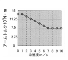
- FIG. 2 shows an example of the conversion table 50.
- the target is that the tension of the yarn 14 is 0.16 N (16 gf).
- the torque is constant at 13.5 ⁇ 10 ⁇ 3 N ⁇ m, and even at 7 m / sec or more, it is constant at 7.5 ⁇ 10 ⁇ 3 N ⁇ m.
- the torque to the arm 40 is decreased linearly with respect to the yarn speed.
- the radius of the arm 40 is 7.5 cm, and it is handled by torque for the control of the torque generator 38.
- the torque applied to the arm 40 is Divided by 7.5cm of radius, it may be expressed by force such as gf unit (1gf is about 0.01N). Since the target yarn tension changes depending on the strength of the yarn and whether the yarn is knitted with one yarn or two yarns, a plurality of conversion tables 50 are provided. In order to obtain the data of the conversion table 50, the torque to the arm 40 is controlled so that the tension of the thread 14 becomes a target value by, for example, the tension sensor 47 for various thread speeds. Even if the arm 40 is feedback-controlled by the tension sensor 47 for the knitting and knitting, the tension cannot generally be made constant because of the response delay of the torque generator 38. Therefore, the value of torque necessary to make the yarn tension constant is measured at the portion of the knitting where the yarn speed is constant.
- the high-speed knitting will be described. Even if the conventional flat knitting machine is the fastest, the knitting speed (carriage speed) is about 1.3 m / sec, and the knitting speed corresponds to the knitting width knitted per second. When this is converted into yarn speed, it is about 6.2 m / sec. High-speed knitting refers to knitting with a higher yarn speed than this, specifically knitting at a yarn speed of 7 m / sec or higher (knitting speed 1.47 m / s), more narrowly 7.7 m / sec (knitting speed) Then, it means knitting at a yarn speed of 1.6m / s) or higher.
- the need to control arm torque and prevent fluctuations in tension is not limited to high-speed knitting.
- the yarn may break even with a slight change in tension.
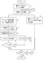
- Fig. 3 shows the algorithm of the embodiment.
- knitting data is input from a storage medium such as a CD-ROM or USB memory, or a LAN.
- a conversion table is selected from the knitting data 22 or the user interface of the flat knitting machine 2.
- the knitting data is analyzed by the knitting controller 24 (step 2), and the knitting controller 24 performs knitting by controlling the travel motor 20 and the carriage 6 (step 3).
- step 4 On the yarn feeder 4 side, the carriage traveling speed, the loop length for each stitch, the number of stitches to be formed, and the like are obtained from the knitting data, and the necessary yarn within a predetermined time, for example, 1 msec to 10 msec. Is determined, that is, the yarn speed (step 4).
- step 5 the yarn speed is converted into arm torque by the conversion table 50.
- step 6 the yarn corresponding to the yarn speed is sent out by the servo motor 32, and the torque generator 38 is controlled by the control unit 39 in accordance with the obtained arm torque (step 7).
- the rotation angle ⁇ of the buffer arm 40 is detected by the constant ⁇ sensor 42, and when ⁇ exceeds an allowable range such as ⁇ 5 °, the arm torque is corrected via the control unit 39 (steps 8 and 9). Since the servo motor 32 always feeds the yarn for the yarn speed, the rotation angle ⁇ is kept constant if there are no factors such as fluctuations in yarn tension or errors in yarn consumption.
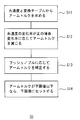
- FIG. 4 shows a conversion algorithm from yarn speed to torque in step 5 of FIG.
- the arm torque is obtained from the conversion table 50 using the table of FIG. If the change rate of the yarn speed is positive, the arm torque obtained in step 11 is reduced according to the change rate (step 12).
- the arm torque may be reduced by a value proportional to the rate of change, or an appropriate threshold value may be provided, and the arm torque may be reduced when the rate of change is greater than the threshold value.
- the arm torque may be reduced in proportion to the power.
- the movement direction of the carrier 12 is a pull, that is, a direction in which the yarn 14 is pulled out from the buffer arm 40 or a push, that is, a direction in which the carrier 12 moves toward the arm 40 is already reflected in the yarn speed.
- step 14 the arm torque is further corrected in step 13 depending on whether it is push or pull. If the arm torque is made extremely small, the yarn 14 sags. Therefore, a lower limit is provided, and if the arm torque is less than the lower limit in steps 11 to 13, the lower limit is set (step 14).
- FIG. 5 shows a control pattern of arm torque in the yarn knitting knitting, that is, pull knitting.
- the carrier is knitted from left to right, and the movement of the carrier is started before the formation of the stitches. Therefore, the yarn speed is generated, and the yarn is fed out at a speed equal to the yarn speed.
- the carrier has already traveled at a constant speed, so that the yarn speed is also constant.
- the number of knitting needles for operating the yarn 14 increases.
- the number of knitting needles is the number of knitting needles that simultaneously form stitches by the cam 18 of the carriage 6.
- the yarn speed reaches a constant value after further increasing from the yarn speed at the position of the first knitting needle.
- the knitting is changed to the knitting.
- the number of knitting needles gradually decreases, and accordingly, the yarn speed also gradually decreases.
- the yarn speed becomes zero.
- the arm torque is kept at a relatively high value to prevent the yarn from sagging during a pause, and since the yarn speed is low until the first knitting needle starts operating the yarn, the torque on the left side of FIG.
- the arm torque is decreased as the yarn speed increases until the yarn speed reaches a constant value.
- an abnormal tension peak may occur in the yarn, particularly from the latter half of the knitting to the beginning of the knitting.
- the arm torque is reduced in accordance with the rate of change of the yarn speed. For this reason, the arm torque is reduced to, for example, a lower limit value from the latter half of the knitting to the initial stage of knitting.
- the arm torque is returned to a value corresponding to a constant yarn speed during knitting, and when the yarn speed is reduced during knitting, the arm torque is gradually increased, and when the carrier entrainment is released, the arm torque is set to a constant value. Keep it at rest.
- the arm 40 Since the torque generator 38 consumes, for example, a current of about 100 mA, for example, the arm 40 is locked or a predetermined length of yarn is rewound by the servo motor 32 in order to stop the torque generator 38 while the carrier is not entrained. It is preferable to prevent the yarn from sagging. In the embodiment, correction according to the rate of change of the yarn speed is performed. However, this correction may be omitted, and the arm torque may be controlled only by the yarn speed value.
- Fig. 6 shows a pattern during yarn pushing knitting (push knitting), and the carriage runs from right to left in the figure. Since the yarn is knitted, play of the yarn occurs when the carrier is brought together. Therefore, the servo motor 32 is reversed to absorb the yarn of play. Since the maximum value of the yarn speed is small in yarn pushing knitting, the control is simple.When knitting is started, the arm torque is linearly reduced to the yarn speed by knitting, the arm torque is kept constant during knitting, and knitting is performed by knitting. The arm torque is increased slightly before the number of knitting needles to be performed and the yarn speed starts to decrease to prevent the yarn from sagging.
- FIG. 7 shows a pattern of the target value of the arm torque in the embodiment
- FIG. 7 is a yarn drawing knitting
- one scale in the longitudinal direction of the arm torque is equivalent to, for example, 10 gf (about 0.0075 N ⁇ m) in terms of tension.
- One scale of the tension is equivalent to, for example, 10 gf (about 0.0075 N ⁇ m).
- the maximum yarn speed is 7.7 m / sec.
- the arm has a radius of 7.5 cm, the arm rotation angle ⁇ is negative on the upper side, and the yarn is fed out from the arm.
- the torque is reduced immediately before the yarn speed starts increasing, and the torque is reduced in accordance with both the yarn speed itself and the rate of change of the yarn speed. Then, the torque is set to the minimum value near the time when the yarn speed reaches the maximum value before reaching the maximum value. Then, the torque is kept substantially constant during knitting, and when the knitting is finished, the torque is returned to the original value. During this time, the yarn tension fluctuates as shown in FIG. 7, and the arm turning angle ⁇ becomes slightly negative during knitting, and it can be seen that the arm is pulled to the carrier side and the yarn is fed out.
- FIG. 9 shows an example in which the torque is kept constant during knitting for the same knitting data, which corresponds to the conventional example in which the arm is urged by a constant tension spring.
- the value of the yarn tension peak is equivalent to 40 gf (about 0.4 N).
- a torque generator that responds at a speed of 1 msec or less is required. Since it is difficult to change the coil current for generating torque suddenly, it is extremely expensive.
- the rotation angle ⁇ changes slightly ahead of the tension peak. Therefore, it is more efficient to apply the feedback based on the rotation angle ⁇ in the initial stage from knitting to knitting. Peaks can be relaxed.
- FIG. 8 (embodiment, controlling arm torque according to yarn speed, but omitting correction for rapid increase in yarn speed) and FIG. 10 (arm) Conventional example with torque fixed at 7.5 ⁇ 10 -3 N ⁇ m).
- the thread tension is 10 gf (0.1 N) per scale.
- the arm torque is 10 gf (0.1 N) per scale in terms of tension with an arm radius of 7.5 cm, and the time scale is 20 ms.
- the maximum value of the yarn tension is reduced to 27 gf (0.27 N) by using the table 50 and decreasing the arm torque as the yarn speed increases. N).
- the tension peak can be further reduced.
- the yarn speed is obtained by pre-reading the knitting data, and by adding the torque according to the yarn speed value and the rate of change, the yarn tension fluctuation This makes it possible to knit a knitted fabric with no stitch breakage and uniform stitch sizes.
Landscapes
- Engineering & Computer Science (AREA)
- Textile Engineering (AREA)
- Knitting Machines (AREA)
- Looms (AREA)
- Braiding, Manufacturing Of Bobbin-Net Or Lace, And Manufacturing Of Nets By Knotting (AREA)
Abstract
Priority Applications (5)
| Application Number | Priority Date | Filing Date | Title |
|---|---|---|---|
| EP10786029.8A EP2441868B1 (fr) | 2009-06-09 | 2010-05-18 | Dispositif d'alimentation en fil et procédé d'alimentation en fil pour machine à tricoter |
| CN201080025078.9A CN102482814B (zh) | 2009-06-09 | 2010-05-18 | 织机用的给纱装置和给纱方法 |
| JP2011518375A JP5603861B2 (ja) | 2009-06-09 | 2010-05-18 | 編機用の糸送り装置と糸送り方法 |
| KR1020117026218A KR101537940B1 (ko) | 2009-06-09 | 2010-05-18 | 편성기용의 실 이송장치와 실 이송방법 |
| US13/376,958 US8249739B2 (en) | 2009-06-09 | 2010-05-18 | Yarn feeding device and yarn feeding method for knitting machine |
Applications Claiming Priority (2)
| Application Number | Priority Date | Filing Date | Title |
|---|---|---|---|
| JP2009-138365 | 2009-06-09 | ||
| JP2009138365 | 2009-06-09 |
Publications (1)
| Publication Number | Publication Date |
|---|---|
| WO2010143498A1 true WO2010143498A1 (fr) | 2010-12-16 |
Family
ID=43308757
Family Applications (1)
| Application Number | Title | Priority Date | Filing Date |
|---|---|---|---|
| PCT/JP2010/058341 Ceased WO2010143498A1 (fr) | 2009-06-09 | 2010-05-18 | Dispositif d'alimentation en fil et procédé d'alimentation en fil pour machine à tricoter |
Country Status (6)
| Country | Link |
|---|---|
| US (1) | US8249739B2 (fr) |
| EP (1) | EP2441868B1 (fr) |
| JP (1) | JP5603861B2 (fr) |
| KR (1) | KR101537940B1 (fr) |
| CN (1) | CN102482814B (fr) |
| WO (1) | WO2010143498A1 (fr) |
Cited By (1)
| Publication number | Priority date | Publication date | Assignee | Title |
|---|---|---|---|---|
| JP2016211112A (ja) * | 2015-05-12 | 2016-12-15 | 株式会社島精機製作所 | 移動糸ガイドを備える横編機 |
Families Citing this family (2)
| Publication number | Priority date | Publication date | Assignee | Title |
|---|---|---|---|---|
| JP6108882B2 (ja) * | 2013-03-05 | 2017-04-05 | 株式会社島精機製作所 | 横編機と横編機での編成方法 |
| ITUA20163183A1 (it) * | 2016-05-05 | 2017-11-05 | Btsr Int Spa | Metodo per il monitoraggio e controllo dell’alimentazione di un filo ad un macchina tessile e relativo dispositivo di alimentazione. |
Citations (6)
| Publication number | Priority date | Publication date | Assignee | Title |
|---|---|---|---|---|
| JPH0416030B2 (fr) | 1986-12-18 | 1992-03-19 | Nippon Jidosha Buhin Sogo Kenkyusho Kk | |
| JPH11500500A (ja) * | 1995-10-06 | 1999-01-12 | メミンガー−イロ・ゲーエムベーハー | 電子制御給糸装置 |
| JP2951068B2 (ja) | 1990-10-12 | 1999-09-20 | メミンガー−イロ ゲゼルシャフト ミット ベシュレンクテル ハフツング | 編目を形成する繊維機械において繊維を制御する方法および装置 |
| JP2005120531A (ja) * | 2003-10-17 | 2005-05-12 | Shima Seiki Mfg Ltd | 横編機の糸供給装置 |
| JP2006169675A (ja) | 2004-12-16 | 2006-06-29 | Shima Seiki Mfg Ltd | 横編機の給糸装置 |
| JP4016030B2 (ja) * | 2002-07-24 | 2007-12-05 | 株式会社島精機製作所 | 横編機の給糸装置 |
Family Cites Families (8)
| Publication number | Priority date | Publication date | Assignee | Title |
|---|---|---|---|---|
| DE3627731C1 (de) * | 1986-08-16 | 1988-03-31 | Gustav Memminger | Fadenliefervorrichtung mit elektronischer Fadenspannungsregelung |
| DE3732102C1 (de) * | 1987-09-24 | 1989-05-03 | Gustav Memminger | Fadenliefervorrichtung fuer Textilmaschinen mit zeitlich unterschiedlichem Fadenverbrauch,insbesondere Strick- und Wirkmaschinen |
| JPH06264342A (ja) * | 1993-03-12 | 1994-09-20 | Tsudakoma Corp | 編み地制御装置 |
| SE508469C2 (sv) * | 1993-04-21 | 1998-10-12 | Sipra Patent Beteiligung | Garnmataranordning i en textilmaskin samt förfarande för användning av garnmataranordning |
| DE19537215C2 (de) * | 1995-10-06 | 1999-09-02 | Memminger Iro Gmbh | Fadenliefergerät für elastische Garne |
| DE19801643A1 (de) * | 1998-01-17 | 1999-07-22 | Stoll & Co H | Verfahren zur Herstellung eines Gestricks auf einer Flachstrickmaschine |
| JP2000262030A (ja) * | 1999-03-11 | 2000-09-22 | Denso Corp | トルクモータ |
| JP4489702B2 (ja) * | 2003-04-18 | 2010-06-23 | 株式会社島精機製作所 | 弾性糸使用の編成方法および装置 |
-
2010
- 2010-05-18 WO PCT/JP2010/058341 patent/WO2010143498A1/fr not_active Ceased
- 2010-05-18 KR KR1020117026218A patent/KR101537940B1/ko active Active
- 2010-05-18 CN CN201080025078.9A patent/CN102482814B/zh active Active
- 2010-05-18 JP JP2011518375A patent/JP5603861B2/ja active Active
- 2010-05-18 EP EP10786029.8A patent/EP2441868B1/fr active Active
- 2010-05-18 US US13/376,958 patent/US8249739B2/en active Active
Patent Citations (6)
| Publication number | Priority date | Publication date | Assignee | Title |
|---|---|---|---|---|
| JPH0416030B2 (fr) | 1986-12-18 | 1992-03-19 | Nippon Jidosha Buhin Sogo Kenkyusho Kk | |
| JP2951068B2 (ja) | 1990-10-12 | 1999-09-20 | メミンガー−イロ ゲゼルシャフト ミット ベシュレンクテル ハフツング | 編目を形成する繊維機械において繊維を制御する方法および装置 |
| JPH11500500A (ja) * | 1995-10-06 | 1999-01-12 | メミンガー−イロ・ゲーエムベーハー | 電子制御給糸装置 |
| JP4016030B2 (ja) * | 2002-07-24 | 2007-12-05 | 株式会社島精機製作所 | 横編機の給糸装置 |
| JP2005120531A (ja) * | 2003-10-17 | 2005-05-12 | Shima Seiki Mfg Ltd | 横編機の糸供給装置 |
| JP2006169675A (ja) | 2004-12-16 | 2006-06-29 | Shima Seiki Mfg Ltd | 横編機の給糸装置 |
Non-Patent Citations (1)
| Title |
|---|
| See also references of EP2441868A4 * |
Cited By (1)
| Publication number | Priority date | Publication date | Assignee | Title |
|---|---|---|---|---|
| JP2016211112A (ja) * | 2015-05-12 | 2016-12-15 | 株式会社島精機製作所 | 移動糸ガイドを備える横編機 |
Also Published As
| Publication number | Publication date |
|---|---|
| EP2441868B1 (fr) | 2015-10-21 |
| JPWO2010143498A1 (ja) | 2012-11-22 |
| KR101537940B1 (ko) | 2015-07-20 |
| US8249739B2 (en) | 2012-08-21 |
| US20120079856A1 (en) | 2012-04-05 |
| EP2441868A1 (fr) | 2012-04-18 |
| CN102482814B (zh) | 2014-03-05 |
| JP5603861B2 (ja) | 2014-10-08 |
| CN102482814A (zh) | 2012-05-30 |
| EP2441868A4 (fr) | 2014-06-04 |
| KR20120088539A (ko) | 2012-08-08 |
Similar Documents
| Publication | Publication Date | Title |
|---|---|---|
| JP3603031B2 (ja) | 給糸装置 | |
| KR101025746B1 (ko) | 횡편기의 편사공급 장치 | |
| JP5603861B2 (ja) | 編機用の糸送り装置と糸送り方法 | |
| EP3401428B1 (fr) | Dispositif d'alimentation en fil pour fil élastique de machine à tricoter recitligne | |
| CN101233270B (zh) | 横编机的供纱装置 | |
| JP6953452B2 (ja) | 織り糸供給装置、織り糸供給装置のコントロール方法、及びコンピュータプログラムプロダクト | |
| WO2010021151A1 (fr) | Machine à tricoter rectiligne | |
| JP6586921B2 (ja) | タンクの製造方法 | |
| JP4366288B2 (ja) | 編機と編機での糸加工方法、並びに編機での糸加工制御装置とそのプログラム | |
| JP5330371B2 (ja) | 弾性糸使用の編地編成装置および方法 | |
| TWI845850B (zh) | 絲線捲繞機 | |
| WO2009116419A1 (fr) | Métier à mailles cueillies et procédé de tricotage utilisant le chevalement du métier à mailles cueillies | |
| JP5368205B2 (ja) | トラバース装置の制御装置 | |
| JP6465742B2 (ja) | 移動糸ガイドを備える横編機 | |
| WO2010143499A1 (fr) | Machine à tricoter | |
| CN121629616A (zh) | 一种横机的送纱方法 |
Legal Events
| Date | Code | Title | Description |
|---|---|---|---|
| WWE | Wipo information: entry into national phase |
Ref document number: 201080025078.9 Country of ref document: CN |
|
| 121 | Ep: the epo has been informed by wipo that ep was designated in this application |
Ref document number: 10786029 Country of ref document: EP Kind code of ref document: A1 |
|
| ENP | Entry into the national phase |
Ref document number: 20117026218 Country of ref document: KR Kind code of ref document: A |
|
| WWE | Wipo information: entry into national phase |
Ref document number: 2011518375 Country of ref document: JP |
|
| WWE | Wipo information: entry into national phase |
Ref document number: 13376958 Country of ref document: US |
|
| NENP | Non-entry into the national phase |
Ref country code: DE |
|
| WWE | Wipo information: entry into national phase |
Ref document number: 2010786029 Country of ref document: EP |