WO2010143596A1 - Procédé pour la production d'oxyde de zinc contenant du magnésium, oxyde de zinc contenant du magnésium et son appareil de production - Google Patents
Procédé pour la production d'oxyde de zinc contenant du magnésium, oxyde de zinc contenant du magnésium et son appareil de production Download PDFInfo
- Publication number
- WO2010143596A1 WO2010143596A1 PCT/JP2010/059550 JP2010059550W WO2010143596A1 WO 2010143596 A1 WO2010143596 A1 WO 2010143596A1 JP 2010059550 W JP2010059550 W JP 2010059550W WO 2010143596 A1 WO2010143596 A1 WO 2010143596A1
- Authority
- WO
- WIPO (PCT)
- Prior art keywords
- magnesium
- vapor
- zinc
- zinc oxide
- mixed
- Prior art date
- Legal status (The legal status is an assumption and is not a legal conclusion. Google has not performed a legal analysis and makes no representation as to the accuracy of the status listed.)
- Ceased
Links
Images

Classifications
-
- C—CHEMISTRY; METALLURGY
- C09—DYES; PAINTS; POLISHES; NATURAL RESINS; ADHESIVES; COMPOSITIONS NOT OTHERWISE PROVIDED FOR; APPLICATIONS OF MATERIALS NOT OTHERWISE PROVIDED FOR
- C09K—MATERIALS FOR MISCELLANEOUS APPLICATIONS, NOT PROVIDED FOR ELSEWHERE
- C09K11/00—Luminescent materials, e.g. electroluminescent or chemiluminescent
- C09K11/08—Luminescent materials, e.g. electroluminescent or chemiluminescent containing inorganic luminescent materials
- C09K11/55—Luminescent materials, e.g. electroluminescent or chemiluminescent containing inorganic luminescent materials containing beryllium, magnesium, alkali metals or alkaline earth metals
-
- B—PERFORMING OPERATIONS; TRANSPORTING
- B82—NANOTECHNOLOGY
- B82Y—SPECIFIC USES OR APPLICATIONS OF NANOSTRUCTURES; MEASUREMENT OR ANALYSIS OF NANOSTRUCTURES; MANUFACTURE OR TREATMENT OF NANOSTRUCTURES
- B82Y30/00—Nanotechnology for materials or surface science, e.g. nanocomposites
-
- C—CHEMISTRY; METALLURGY
- C01—INORGANIC CHEMISTRY
- C01G—COMPOUNDS CONTAINING METALS NOT COVERED BY SUBCLASSES C01D OR C01F
- C01G9/00—Compounds of zinc
- C01G9/02—Oxides; Hydroxides
-
- C—CHEMISTRY; METALLURGY
- C01—INORGANIC CHEMISTRY
- C01P—INDEXING SCHEME RELATING TO STRUCTURAL AND PHYSICAL ASPECTS OF SOLID INORGANIC COMPOUNDS
- C01P2002/00—Crystal-structural characteristics
- C01P2002/50—Solid solutions
-
- C—CHEMISTRY; METALLURGY
- C01—INORGANIC CHEMISTRY
- C01P—INDEXING SCHEME RELATING TO STRUCTURAL AND PHYSICAL ASPECTS OF SOLID INORGANIC COMPOUNDS
- C01P2002/00—Crystal-structural characteristics
- C01P2002/50—Solid solutions
- C01P2002/52—Solid solutions containing elements as dopants
-
- C—CHEMISTRY; METALLURGY
- C01—INORGANIC CHEMISTRY
- C01P—INDEXING SCHEME RELATING TO STRUCTURAL AND PHYSICAL ASPECTS OF SOLID INORGANIC COMPOUNDS
- C01P2002/00—Crystal-structural characteristics
- C01P2002/70—Crystal-structural characteristics defined by measured X-ray, neutron or electron diffraction data
- C01P2002/72—Crystal-structural characteristics defined by measured X-ray, neutron or electron diffraction data by d-values or two theta-values, e.g. as X-ray diagram
-
- C—CHEMISTRY; METALLURGY
- C01—INORGANIC CHEMISTRY
- C01P—INDEXING SCHEME RELATING TO STRUCTURAL AND PHYSICAL ASPECTS OF SOLID INORGANIC COMPOUNDS
- C01P2004/00—Particle morphology
- C01P2004/60—Particles characterised by their size
- C01P2004/62—Submicrometer sized, i.e. from 0.1-1 micrometer
-
- C—CHEMISTRY; METALLURGY
- C01—INORGANIC CHEMISTRY
- C01P—INDEXING SCHEME RELATING TO STRUCTURAL AND PHYSICAL ASPECTS OF SOLID INORGANIC COMPOUNDS
- C01P2004/00—Particle morphology
- C01P2004/60—Particles characterised by their size
- C01P2004/64—Nanometer sized, i.e. from 1-100 nanometer
-
- C—CHEMISTRY; METALLURGY
- C01—INORGANIC CHEMISTRY
- C01P—INDEXING SCHEME RELATING TO STRUCTURAL AND PHYSICAL ASPECTS OF SOLID INORGANIC COMPOUNDS
- C01P2006/00—Physical properties of inorganic compounds
- C01P2006/80—Compositional purity
-
- Y—GENERAL TAGGING OF NEW TECHNOLOGICAL DEVELOPMENTS; GENERAL TAGGING OF CROSS-SECTIONAL TECHNOLOGIES SPANNING OVER SEVERAL SECTIONS OF THE IPC; TECHNICAL SUBJECTS COVERED BY FORMER USPC CROSS-REFERENCE ART COLLECTIONS [XRACs] AND DIGESTS
- Y10—TECHNICAL SUBJECTS COVERED BY FORMER USPC
- Y10T—TECHNICAL SUBJECTS COVERED BY FORMER US CLASSIFICATION
- Y10T428/00—Stock material or miscellaneous articles
- Y10T428/29—Coated or structually defined flake, particle, cell, strand, strand portion, rod, filament, macroscopic fiber or mass thereof
- Y10T428/2982—Particulate matter [e.g., sphere, flake, etc.]
Definitions
- the present invention relates to a method for producing magnesium-containing zinc oxide that can be used as a blue phosphor and the like, and an apparatus for producing the same.
- Magnesium-containing zinc oxide in which magnesium oxide is partly dissolved in zinc oxide, has a hexagonal wurtzite crystal structure and exhibits blue light emission due to electron beam irradiation and ultraviolet excitation by introducing oxygen defects. It is known (Non-Patent Document 1). Among them, magnesium-containing zinc oxide, in which magnesium is dissolved in a high concentration, has high luminous efficiency, is rich in raw materials such as zinc and magnesium, and is non-polluting. Can be used as a body.
- Examples of methods for producing such magnesium-containing zinc oxide include a solid phase reaction method, a coprecipitation method, and a hydrothermal synthesis method.
- the solid-phase reaction method can produce magnesium-containing zinc oxide at low cost and in large quantities by reacting zinc oxide powder and magnesium oxide powder in the solid phase, but the solid solution limit of magnesium in the solid phase reaction Is about 2 mol%, so even if magnesium is reacted at a rate exceeding the composition of Zn 0.98 Mg 0.02 O, cubic MgO is precipitated, and magnesium is dissolved in zinc oxide at a high concentration. There is a problem that can not be.
- Non-patent Document 1 a method in which a solid phase reaction is carried out in the presence of a flux such as potassium chloride so that magnesium is dissolved in a maximum of 20 mol%.
- a flux such as potassium chloride so that magnesium is dissolved in a maximum of 20 mol%
- the product contains a large amount of impurities, and it is difficult to remove the flux component, but it is difficult.
- the solid phase reaction method since it is necessary to raise the reaction temperature to 1300 ° C. or higher, there is a problem that it is difficult to obtain magnesium-containing zinc oxide having a uniform composition by sublimation of zinc oxide.
- the zinc oxide powder has a high purity, a uniform particle size, and good dispersibility.
- zinc oxide is in the form of aggregated particles. Since it produces
- magnesium-containing zinc oxide in which magnesium is dissolved in a high concentration can be produced at a low temperature of 1000 ° C. or lower.
- a mixed aqueous solution in which zinc and magnesium are dissolved and an organic acid component are mixed to coprecipitate an organic acid double salt, and the resulting organic acid double salt is thermally decomposed Patent Document 1, Non-Patent Document 1).
- Patent Document 2 Patent Document 2,
- magnesium-containing zinc oxide in which magnesium is dissolved in a high concentration can be produced at a low temperature.
- a method is known in which a magnesium-containing zinc oxide layer is formed on a fine substrate such as zinc oxide or sapphire to form particles (Patent Document 2).
- an object of the present invention is to provide a magnesium-containing zinc oxide production method and production apparatus capable of efficiently producing a large amount of magnesium-containing zinc oxide having a high purity, a small amount of impurities, and a uniform and high magnesium content. .
- the present inventors have conducted extensive research, and as a result, zinc vapor and magnesium vapor are mixed in an excess state of zinc vapor and reacted with an oxidizing gas to achieve high purity. It has been found that a uniform magnesium-containing zinc oxide with few impurities can be efficiently produced in large quantities. That is, the present invention includes a step of heating zinc metal to generate zinc vapor, a step of heating magnesium metal to generate magnesium vapor, and mixing the zinc vapor and the magnesium vapor to generate mixed vapor. And a step of bringing an oxidizing gas into contact with the mixed vapor to produce magnesium-containing zinc oxide, wherein the zinc content in the mixed vapor is greater than magnesium. It is a manufacturing method.
- the present invention also includes zinc vapor generating means for heating zinc metal to generate zinc vapor, magnesium vapor generating means for heating metal magnesium to generate magnesium vapor, and mixing the zinc vapor and the magnesium vapor.
- Mixed steam generating means for generating mixed steam, and oxidizing gas contact means for generating magnesium-containing zinc oxide by bringing an oxidizing gas into contact with the mixed steam, and the zinc content in the mixed steam is: It is an apparatus for producing magnesium-containing zinc oxide, characterized in that it is adjusted to be more than magnesium.
- the metal zinc used as a raw material preferably has a purity of 99.9% by mass or more, for example, 3N (three nines) such as electrolytic zinc. )
- a level of purity of metallic zinc can be used.
- the metal magnesium used as a raw material preferably has a purity of 99.9% by mass or more.
- a metal magnesium having a purity of 3N (three nines) by an electrolytic method or a thermal reduction method can be used.
- a method for producing magnesium-containing zinc oxide and an apparatus for producing the same which can efficiently produce a large amount of magnesium-containing zinc oxide having high purity, few impurities, uniform and high magnesium content. be able to.
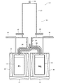
- the magnesium-containing zinc oxide production apparatus 10 includes a zinc vapor generation unit 11 that heats metallic zinc to generate zinc vapor, a magnesium vapor generation unit 15 that is arranged in parallel with the zinc vapor generation unit 11, and zinc vapor generation.
- the mixed steam jet nozzle 20 is disposed above the section 11 and the magnesium steam generating section 15 and mixes the zinc steam and the magnesium steam to eject the mixed steam.
- the mixed steam jet nozzle 20 is disposed above the mixed steam jet nozzle 20.
- An oxidizing gas contact portion 19 that reacts with gas is provided.
- the zinc vapor generation unit 11 includes a zinc storage container 12 in which metallic zinc is stored, a heat source 14 disposed so as to cover other than the upper surface of the zinc storage container 12, and a mixed steam ejection nozzle from the center of the upper surface of the zinc storage container 12. 20 and a zinc vapor jet nozzle 24 connected to 20.
- the zinc container 12 contains metal zinc inside, and its shape is not particularly limited, but a cylindrical one is preferable.
- a carrier gas introduction pipe 26 for introducing a carrier gas into the zinc container 12 from the outside is connected to the outside of the center of the upper surface of the zinc container 12.
- the heat source 14 is not particularly limited as long as the metal zinc can be heated to steam. For example, resistance heating, flame heating, and high frequency heating can be mentioned.
- the zinc vapor generating means includes a zinc container that contains metallic zinc, a heat source that covers a portion other than the upper surface of the zinc container, and a zinc vapor jet nozzle that jets zinc vapor into the mixed vapor jet nozzle, and further includes a carrier.
- a zinc vapor generating part to which a carrier gas introduction pipe for introducing gas into the zinc container is connected is preferred.
- the magnesium vapor generation unit 15 includes a magnesium storage container 16 in which metallic magnesium is stored, a heat source 18 disposed so as to cover other than the upper surface of the magnesium storage container 16, and a mixed steam ejection nozzle from the center of the upper surface of the magnesium storage container 16. And a magnesium vapor ejection nozzle 28 extending into the interior 20.
- the magnesium container 16 contains metal magnesium inside, and its shape is not particularly limited, but a cylindrical one is preferable.
- a carrier gas introduction pipe 30 for introducing a carrier gas into the magnesium container 16 from the outside is connected to the outside of the center of the upper surface of the magnesium container 16.
- the heat source 18 is not particularly limited as long as the metal magnesium can be heated to vapor. For example, resistance heating, flame heating, and high frequency heating can be mentioned.
- the magnesium vapor generating means includes a magnesium container containing metal magnesium, a heat source covering the area other than the upper surface of the magnesium container, and a magnesium vapor jet nozzle for jetting magnesium vapor into the mixed vapor jet nozzle, and further a carrier A magnesium vapor generating part connected to a carrier gas introduction pipe for introducing gas into the magnesium storage container is preferred.
- the mixed vapor jet nozzle 20 is a bottomed cylindrical nozzle having a jet port opened upward, and the jet port of the zinc vapor jet nozzle 24 is connected to the center of the bottom. Further, from a position other than the center of the bottom surface of the mixed vapor jet nozzle 20, the magnesium vapor jet nozzle 28 curves upward from the position of the bottom surface to the position of the central axis in the mixed vapor jet nozzle 20. Along the axial direction, it extends into the mixed vapor jet nozzle 20. The magnesium vapor ejection nozzle 28 is opened upward at a position where the diameter is smaller than the mixed vapor ejection nozzle 20 and lower than the opening of the mixed vapor ejection nozzle 20.
- the zinc vapor ejection nozzle 24 and the magnesium ejection nozzle 28 are positioned upstream of the ejection port of the mixed vapor ejection nozzle 20 and are disposed so that the ejected zinc vapor and magnesium vapor are sufficiently mixed.
- the mixed steam jet nozzle 20 may be connected to a swirl nozzle or may be provided with a swirl blade.
- the mixed steam generating means the above-mentioned mixing is performed, in which the jet outlet is opened upward, the jet outlet of the zinc vapor jet nozzle is connected to the bottom, and the magnesium jet nozzle extends from the bottom to the inside.
- a steam jet nozzle is preferably mentioned.
- the upper surface of the zinc container 12 and the upper surface of the magnesium container 16, the zinc vapor ejection nozzle 24, the magnesium vapor ejection nozzle 28, and the mixed vapor ejection nozzle 20 are covered with a heat source 32.
- the heat source 32 is not particularly limited as long as zinc and magnesium can be heated to the boiling point or higher, and examples thereof include resistance heating, flame heating, and high-frequency heating.
- the oxidizing gas contact portion 19 includes a columnar oxidation reaction vessel 21 and an oxidizing gas introduction means at a position on the side surface above the bottom surface of the oxidation reaction vessel 21 and does not impair the efficiency of the oxidation reaction.
- the oxidizing gas introducing means for example, an oxidizing gas supply nozzle 22 or the like is used.
- a mixed vapor jet nozzle 20 is connected to the center of the bottom surface of the oxidation reaction vessel 21.
- two oxidizing gas supply nozzles 22 are provided at equal intervals in the circumferential direction, the interval and the number are not limited at all.
- the number of the oxidizing gas supply nozzles 22 is preferably plural, and more preferably 2 to 4.
- a discharge port 34 for discharging the magnesium-containing zinc oxide is provided at the center of the upper surface of the oxidation reaction vessel 21.
- Preferred examples of the oxidizing gas contact means include the oxidizing gas contact portion provided with an oxidation reaction vessel and an oxidizing gas introduction nozzle.
- the metallic zinc accommodated in the zinc accommodating container 12 is heated by the heat source 14 to a boiling point of zinc or higher, for example, 1000 ° C. or higher, preferably 1000 to 1200 ° C. to generate zinc vapor.
- the magnesium metal housed in the magnesium container 16 is heated by the heat source 18 to a boiling point of magnesium or higher, for example, 1200 ° C. or higher, preferably 1200 to 1400 ° C. to generate magnesium vapor.
- the generated zinc vapor flows into the zinc vapor ejection nozzle 24, and the magnesium vapor flows into the magnesium vapor ejection nozzle 28.
- the carrier gas is preferably heated and supplied in advance so as not to lower the temperature of zinc vapor and magnesium vapor.
- the carrier gas introduced into the zinc container 12 is heated to 1000 to 1200 ° C.
- the carrier gas introduced into the magnesium container 16 is heated to 1200 to 1400 ° C.
- the zinc vapor is jetted from the jet outlet to the mixed vapor jet nozzle 20 through the zinc vapor jet nozzle 24.
- Magnesium vapor is ejected from the ejection port into the mixed vapor ejection nozzle 20 through the magnesium vapor ejection nozzle 28. Since the jet outlet of the magnesium vapor jet nozzle 28 is located in the mixed steam jet nozzle 20 below the jet outlet of the mixed steam jet nozzle 20 and above the jet outlet of the zinc vapor jet nozzle 24, the magnesium vapor is It will be ejected into the zinc vapor flowing through the mixed vapor ejection nozzle 20. Therefore, zinc vapor and magnesium vapor are mixed efficiently.
- the zinc vapor ejection nozzle 24, the magnesium vapor ejection nozzle 28, and the mixed vapor ejection nozzle 20 are preferably heated to 1200 to 1400 ° C. by a heat source 32. Since the temperature of the zinc vapor is lower than the temperature of the magnesium vapor, when not heated, the magnesium vapor is cooled by the zinc vapor, the magnesium is segregated, and the magnesium-containing zinc oxide in which magnesium is dissolved in a high concentration cannot be obtained. There is a case.
- the mixed steam preferably has a magnesium content (molar ratio) in the range of 0 ⁇ Mg / (Zn + Mg) ⁇ 0.25.
- the magnesium content is more preferably 0.05 or more, particularly preferably 0.08 or more, particularly preferably 0.10 or more, and most preferably more than 0.20. preferable.
- a magnesium content ratio With such a magnesium content ratio, a magnesium-containing zinc oxide having a particularly high magnesium content suitable for a blue phosphor can be obtained.
- a magnesium content rate is 0.25 or less, and when it makes such a magnesium content rate, it can avoid that cubic MgO mixes in a magnesium containing zinc oxide.
- the content ratio of magnesium in the mixed steam can be controlled by, for example, the supply speed of zinc vapor and magnesium vapor.
- the supply speed can be controlled by, for example, the heating temperature of the heat source 14 and the heat source 18 and the amount of carrier gas supplied from the carrier gas supply pipe 26 and the carrier gas supply pipe 30.
- the mixed vapor of zinc vapor and magnesium vapor ejected from the mixed vapor ejection nozzle 20 flows into the oxidation reaction vessel 21 and comes into contact with the oxidizing gas introduced from the oxidizing gas supply nozzle 22.
- the oxidizing gas include air, oxygen, and oxygen-enriched air.
- the magnesium and zinc in the mixed steam are immediately oxidized to produce powdered magnesium-containing acid zinc.
- the particle diameter of the powder can be controlled by the concentration of zinc vapor or magnesium vapor as a raw material, the oxidation reaction temperature, the oxidation reaction time, and the like.
- the evaporation rate of zinc or magnesium as a raw material is increased, the oxidation reaction temperature is increased, the diameter of the mixed vapor jet nozzle 20 is increased, and the air flow velocity is decreased to increase the oxidation reaction time.
- the conditions for the oxidation reaction are not particularly limited, and known conditions employed in the production of zinc oxide by a gas phase method can be employed.
- the produced magnesium-containing zinc oxide is guided and collected from the discharge port 34 to a product collector (not shown) such as a bag filter.
- the magnesium-containing zinc oxide thus obtained is represented by Zn 1-x Mg x O.
- x is preferably larger than 0 and not larger than 0.25, more preferably not smaller than 0.05 and not larger than 0.25, still more preferably not smaller than 0.08 and not larger than 0.25, It is particularly preferably from 0.10 to 0.25, most preferably from greater than 0.20 to 0.25.
- the value of x can be adjusted by the ratio of magnesium contained in the mixed steam.
- the purity of the collected magnesium-containing zinc oxide is preferably 99.9% by mass or more.
- the magnesium-containing zinc oxide can be obtained as a powder having a uniform particle size.
- This powder has a hexagonal wurtzite type crystal structure, and is reduced in zinc oxide (Zn: ZnO) in which magnesium does not form a solid solution by introducing oxygen defects by heat treatment or the like in a reducing atmosphere. Therefore, it can be used as a blue phosphor, particularly a fluorescent display tube or a blue phosphor for field emission.
- Example 1 Metal zinc (manufactured by High Purity Chemical Laboratory: purity 99.9% by mass or more) housed in a zinc container 12 (inner diameter 150 mm, height 200 mm) is heated to 1000 ° C. by a heat source 14, and argon gas is supplied at 10 NL / The gas was supplied from the carrier gas supply pipe 26 in min. Zinc vapor was generated at 0.90 kg / h.
- magnesium metal manufactured by High-Purity Chemical Laboratory: purity 99.9% by mass or more housed in the magnesium container 16 (inner diameter 150 mm, height 200 mm) is heated to 1200 ° C. by the heat source 18, and argon gas is supplied. It was supplied from the carrier gas supply pipe 30 at 1 NL / min. Magnesium vapor was generated at 0.01 kg / h.
- the generated zinc vapor is jetted to the mixed vapor jet nozzle 20 (inner diameter 20 mm, length 50 mm) through the zinc vapor jet nozzle 24 (inner diameter 4 mm). 4 mm, the length in the mixed steam jet nozzle 20 is 20 mm), and jetted into the mixed steam jet nozzle 20.
- zinc vapor and magnesium vapor were mixed.
- the temperature inside the mixed vapor jet nozzle 20 was the same as that of the magnesium container 16.
- the mixed steam thus mixed was ejected from the mixed steam ejection nozzle 20 into the oxidation reaction vessel 21.
- air was supplied at 100 NL / min from an oxidizing gas supply nozzle, and the mixed vapor and air were brought into contact with each other to carry out an oxidation reaction.
- the magnesium-containing zinc oxide thus produced was collected by being guided to a bag filter (not shown) from the discharge port 34 by a suction fan (not shown), and the magnesium-containing zinc oxide according to Example 1 was obtained.
- the magnesium-containing zinc oxide according to Example 1 was powdery. The manufacturing conditions are shown in Table 1. The obtained magnesium-containing zinc oxide was analyzed as follows.
- composition The composition of magnesium-containing zinc oxide was analyzed by ICP emission analysis. The results are shown in Table 2.
- Crystal phase The crystal structure of magnesium-containing zinc oxide was measured by powder X-ray diffraction. The results are shown in Table 2.
- magnesium solid solution amount The magnesium solid solution amount was determined from the crystal phase measurement result (hexagonal crystal formation) and the composition measurement result (Mg content). The results are shown in Table 2.
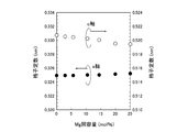
- the lattice constant was determined by powder X-ray diffraction using Si standard powder as an internal standard. The results are shown in Table 2. The relationship between the lattice constant and the magnesium solid solution amount is shown in FIG.
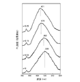
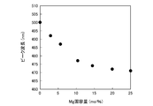
- the peak wavelength of the PL spectrum of magnesium-containing zinc oxide was measured as follows. First, oxygen defects were introduced into the magnesium-containing zinc oxide powder by reducing the magnesium-containing zinc oxide powder at 800 ° C. for 2 hours in an atmosphere containing 5% by volume of hydrogen gas in argon gas. A blue phosphor powder was obtained. The PL spectrum of this powder was measured with a spectrofluorometer (manufactured by JASCO; FP-6500) at an excitation wavelength of 320 nm. The results are shown in Table 2 and FIG. Moreover, the relationship between the peak wavelength of PL spectrum and the amount of Mg solid solution is shown in FIG.
- the metal impurities (Pb, Na, Al, Si, S, K, Ca, Fe, Ni, Cu, Ag, Cd, Te, Bi) of the magnesium-containing zinc oxide were measured by ICP emission analysis.
- the content of metal impurities was 55 ppm, and the purity of magnesium-containing zinc oxide was 99.99% by mass or more. Details of the results of Example 1 are shown in Table 3.
- the magnesium-containing zinc oxide according to Example 1 is composed only of metal zinc and metal magnesium, the obtained magnesium-containing zinc oxide does not contain a halogen component such as fluorine or chlorine.
- Example 2 to 6 Magnesium-containing zinc oxide was obtained in the same manner as in Example 1 except that the conditions described in Table 1 were used. The composition, crystal phase, Mg solid solution amount, lattice constant, and peak wavelength were determined in the same manner as in Example 1, and the results are shown in Table 2. Further, the impurities and the particle size distribution were obtained in the same manner as in Example 1, and the same results were obtained. Since the magnesium-containing zinc oxide according to Examples 2 to 6 is made of only metal zinc and metal magnesium, the obtained magnesium-containing zinc oxide does not contain a halogen component such as fluorine or chlorine.
- a halogen component such as fluorine or chlorine.
- Example 1 Zinc oxide was obtained in the same manner as in Example 1 except that magnesium vapor was not supplied and the conditions described in Table 1 were used. The composition, crystal phase, Mg solid solution amount, lattice constant, and peak wavelength were determined in the same manner as in Example 1, and the results are shown in Table 2.
- the peak wavelength shifts to the short wavelength side as magnesium is dissolved in the range of 25.0 mol% or less, and the zinc oxide blue phosphor It can be seen that is generated.
- the solid solution amount is 10 to 25 mol%
- the peak wavelength shifts to the short wavelength side from 477 to 471 nm, and it can be seen that magnesium-containing zinc oxide suitable as a blue phosphor can be obtained.
- SYMBOLS 10 Magnesium containing zinc oxide manufacturing apparatus 11: Zinc vapor generation part 12: Zinc storage container 14, 18: Heat source 15: Magnesium vapor generation part 16: Magnesium storage container 19: Oxidizing gas contact part 20: Mixed steam injection nozzle 21: Oxidation reaction vessel 22: oxidizing gas supply nozzle
Landscapes
- Chemical & Material Sciences (AREA)
- Engineering & Computer Science (AREA)
- Organic Chemistry (AREA)
- Nanotechnology (AREA)
- Materials Engineering (AREA)
- Inorganic Chemistry (AREA)
- Physics & Mathematics (AREA)
- Composite Materials (AREA)
- Condensed Matter Physics & Semiconductors (AREA)
- General Physics & Mathematics (AREA)
- Crystallography & Structural Chemistry (AREA)
- Inorganic Compounds Of Heavy Metals (AREA)
Abstract
L'invention porte sur un appareil pour la production d'un oxyde de zinc contenant du magnésium, lequel comprend un moyen de production de vapeur de zinc (11) pour la production d'une vapeur de zinc par chauffage de zinc métallique, un moyen de production de vapeur de magnésium (15) pour la production d'une vapeur de magnésium par chauffage de magnésium métallique, un moyen de production de vapeur mélangée (20) pour la production d'une vapeur mélangée par mélange de la vapeur de zinc et de la vapeur de magnésium et un moyen de mise en contact avec du gaz oxydant (19) pour la production d'un oxyde de zinc contenant du magnésium par la mise en contact d'un gaz oxydant avec la vapeur mélangée. La quantité de zinc contenu dans la vapeur mélangée est ajustée pour être plus grande que la quantité de magnésium.
Priority Applications (4)
| Application Number | Priority Date | Filing Date | Title |
|---|---|---|---|
| JP2011518516A JP5644763B2 (ja) | 2009-06-12 | 2010-06-04 | マグネシウム含有酸化亜鉛の製造方法及びマグネシウム含有酸化亜鉛の製造装置 |
| EP10786127.0A EP2441734A4 (fr) | 2009-06-12 | 2010-06-04 | Procédé pour la production d'oxyde de zinc contenant du magnésium, oxyde de zinc contenant du magnésium et son appareil de production |
| US13/377,074 US8388928B2 (en) | 2009-06-12 | 2010-06-04 | Method for producing magnesium-containing zinc oxide, magnesium-containing zinc oxide, and apparatus for producing same |
| US13/758,672 US20130149534A1 (en) | 2009-06-12 | 2013-02-04 | Method for Producing Magnesium-Containing Zinc Oxide, Magnesium-Containing Zinc Oxide, and Apparatus for Producing Same |
Applications Claiming Priority (2)
| Application Number | Priority Date | Filing Date | Title |
|---|---|---|---|
| JP2009-141588 | 2009-06-12 | ||
| JP2009141588 | 2009-06-12 |
Related Child Applications (1)
| Application Number | Title | Priority Date | Filing Date |
|---|---|---|---|
| US13/758,672 Division US20130149534A1 (en) | 2009-06-12 | 2013-02-04 | Method for Producing Magnesium-Containing Zinc Oxide, Magnesium-Containing Zinc Oxide, and Apparatus for Producing Same |
Publications (1)
| Publication Number | Publication Date |
|---|---|
| WO2010143596A1 true WO2010143596A1 (fr) | 2010-12-16 |
Family
ID=43308851
Family Applications (1)
| Application Number | Title | Priority Date | Filing Date |
|---|---|---|---|
| PCT/JP2010/059550 Ceased WO2010143596A1 (fr) | 2009-06-12 | 2010-06-04 | Procédé pour la production d'oxyde de zinc contenant du magnésium, oxyde de zinc contenant du magnésium et son appareil de production |
Country Status (5)
| Country | Link |
|---|---|
| US (2) | US8388928B2 (fr) |
| EP (1) | EP2441734A4 (fr) |
| JP (1) | JP5644763B2 (fr) |
| TW (1) | TW201105586A (fr) |
| WO (1) | WO2010143596A1 (fr) |
Families Citing this family (2)
| Publication number | Priority date | Publication date | Assignee | Title |
|---|---|---|---|---|
| CA2796441C (fr) | 2010-04-26 | 2017-12-12 | Sakai Chemical Industry Co., Ltd. | Particules de charge, composition de resine, graisse, et composition de revetement |
| CN119909613A (zh) * | 2025-04-01 | 2025-05-02 | 西安慧金科技有限公司 | 一种大型氧化亚硅预镁或锂负极材料制备设备及方法 |
Citations (5)
| Publication number | Priority date | Publication date | Assignee | Title |
|---|---|---|---|---|
| JPS61122106A (ja) * | 1984-11-19 | 1986-06-10 | Ube Ind Ltd | 微粉末状マグネシウム酸化物の製造方法 |
| JP2004182519A (ja) * | 2002-12-02 | 2004-07-02 | Ube Material Industries Ltd | 金属マグネシウム溶融蒸発装置、及びこれを用いた高純度酸化マグネシウム微粉末の製造方法 |
| JP2006233047A (ja) | 2005-02-25 | 2006-09-07 | Mie Prefecture | 青色系蛍光体用酸化亜鉛系固溶体及びその製造方法並びに青色系蛍光体及びその製造方法 |
| JP2006335914A (ja) | 2005-06-03 | 2006-12-14 | Sumitomo Electric Ind Ltd | 粉末蛍光体とその製法、およびこれを用いた発光デバイス |
| WO2007144242A2 (fr) * | 2006-06-13 | 2007-12-21 | Evonik Degussa Gmbh | Procédé de préparation de poudres d'oxydes métalliques |
Family Cites Families (2)
| Publication number | Priority date | Publication date | Assignee | Title |
|---|---|---|---|---|
| US6716479B2 (en) * | 2002-01-04 | 2004-04-06 | Rutgers, The State University Of New Jersey | Tailoring piezoelectric properties using MgxZn1-xO/ZnO material and MgxZn1-xO/ZnO structures |
| CN101583742A (zh) * | 2006-12-11 | 2009-11-18 | 鲁门兹公司 | 氧化锌多结光电池和光电器件 |
-
2010
- 2010-06-04 EP EP10786127.0A patent/EP2441734A4/fr not_active Withdrawn
- 2010-06-04 US US13/377,074 patent/US8388928B2/en not_active Expired - Fee Related
- 2010-06-04 WO PCT/JP2010/059550 patent/WO2010143596A1/fr not_active Ceased
- 2010-06-04 JP JP2011518516A patent/JP5644763B2/ja not_active Expired - Fee Related
- 2010-06-09 TW TW099118675A patent/TW201105586A/zh unknown
-
2013
- 2013-02-04 US US13/758,672 patent/US20130149534A1/en not_active Abandoned
Patent Citations (5)
| Publication number | Priority date | Publication date | Assignee | Title |
|---|---|---|---|---|
| JPS61122106A (ja) * | 1984-11-19 | 1986-06-10 | Ube Ind Ltd | 微粉末状マグネシウム酸化物の製造方法 |
| JP2004182519A (ja) * | 2002-12-02 | 2004-07-02 | Ube Material Industries Ltd | 金属マグネシウム溶融蒸発装置、及びこれを用いた高純度酸化マグネシウム微粉末の製造方法 |
| JP2006233047A (ja) | 2005-02-25 | 2006-09-07 | Mie Prefecture | 青色系蛍光体用酸化亜鉛系固溶体及びその製造方法並びに青色系蛍光体及びその製造方法 |
| JP2006335914A (ja) | 2005-06-03 | 2006-12-14 | Sumitomo Electric Ind Ltd | 粉末蛍光体とその製法、およびこれを用いた発光デバイス |
| WO2007144242A2 (fr) * | 2006-06-13 | 2007-12-21 | Evonik Degussa Gmbh | Procédé de préparation de poudres d'oxydes métalliques |
Non-Patent Citations (5)
| Title |
|---|
| G.NING ET AL.: "Structure and optical properties of MgXZn1-XO nanoparticles prepared by sol-gel method", OPTICAL MATERIALS, vol. 27, no. 1, 11 March 2004 (2004-03-11), pages 1 - 5, XP004568553 * |
| MIE PREFECTURAL INDUSTRIAL RESEARCH INSTITUTE, STUDY REPORT, vol. 31, 2007, pages 6 - 10 |
| MIE PREFECTURAL INDUSTRIAL RESEARCH INSTITUTE, STUDY REPORT, vol. 32, 2008, pages 11 - 17 |
| S.OHSHIRO ET AL.: "Low-temperature Synthesis of Nanometer-sized Single Crystals in MgO-ZnO Solid Solution", JOURNAL OF THE JAPAN SOCIETY OF COLOUR MATERIAL, vol. 75, no. 7, 20 July 2002 (2002-07-20), pages 327 - 329, XP008150407 * |
| See also references of EP2441734A4 |
Also Published As
| Publication number | Publication date |
|---|---|
| US20120104318A1 (en) | 2012-05-03 |
| TW201105586A (en) | 2011-02-16 |
| EP2441734A1 (fr) | 2012-04-18 |
| US8388928B2 (en) | 2013-03-05 |
| JP5644763B2 (ja) | 2014-12-24 |
| US20130149534A1 (en) | 2013-06-13 |
| EP2441734A4 (fr) | 2013-08-28 |
| JPWO2010143596A1 (ja) | 2012-11-22 |
Similar Documents
| Publication | Publication Date | Title |
|---|---|---|
| US10189003B1 (en) | Continuous microwave-assisted segmented flow reactor for high-quality nanocrystal synthesis | |
| JP3383608B2 (ja) | ナノ結晶性材料を合成するための装置 | |
| US6689191B2 (en) | Rapid conversion of metal-containing compounds to form metals or metal alloys | |
| JP5343697B2 (ja) | 複合タングステン酸化物超微粒子の製造方法 | |
| RU2489232C1 (ru) | Способ получения наноразмерного порошка металла | |
| JP7116415B2 (ja) | 複合タングステン酸化物粒子の製造方法 | |
| JP2005289798A (ja) | 二酸化チタンナノパウダーの製造方法 | |
| AU2001243276A1 (en) | Rapid conversion of metal-containing compounds to form metals or metal oxides | |
| Hassan et al. | Synthesis of ZnO nanoparticles by a hybrid electrochemical-thermal method: influence of calcination temperature | |
| CN101679860B (zh) | 氧化物发光体 | |
| CN103964475B (zh) | 立方体状氧化镁粉末及其制法 | |
| JP5644763B2 (ja) | マグネシウム含有酸化亜鉛の製造方法及びマグネシウム含有酸化亜鉛の製造装置 | |
| Chen et al. | An effective approach to grow boron nitride nanowires directly on stainless-steel substrates | |
| JP2004124257A (ja) | 金属銅微粒子及びその製造方法 | |
| US20100266845A1 (en) | Magnesium Oxide Powder | |
| JP2022135131A (ja) | 複合タングステン酸化物粒子の製造方法 | |
| JP7302808B2 (ja) | 複合タングステン酸化物粒子の製造方法 | |
| KR20220016841A (ko) | 미립자의 제조 장치 및 미립자의 제조 방법 | |
| Ishigaki | Synthesis of ceramic nanoparticles with non-equilibrium crystal structures and chemical compositions by controlled thermal plasma processing | |
| KR101036484B1 (ko) | 플라즈마 제트를 이용한 산화아연 나노막대의 제조방법 및 이에 의해 제조된 산화아연 나노막대의 광촉매 활성 | |
| WO2021100320A1 (fr) | Microparticules | |
| RU2738596C1 (ru) | Способ получения ультрадисперсных частиц однородных оксидных керамических композиций, состоящих из ядра и внешних оболочек | |
| Hong et al. | The Effect of flux types on the formation of green light emitting phosphor particles with spherical shape and filled morphology | |
| Samokhin et al. | Characteristics of heat and mass transfer to the wall of a confined-jet plasma flow reactor in the processes of nanopowder preparation from metals and their compounds | |
| Ledoux et al. | Host size effects on optical properties of Y2O3: Eu3+ and Gd2O3: Eu3+ nanoparticles synthesized by laser pyrolysis |
Legal Events
| Date | Code | Title | Description |
|---|---|---|---|
| 121 | Ep: the epo has been informed by wipo that ep was designated in this application |
Ref document number: 10786127 Country of ref document: EP Kind code of ref document: A1 |
|
| WWE | Wipo information: entry into national phase |
Ref document number: 2011518516 Country of ref document: JP |
|
| NENP | Non-entry into the national phase |
Ref country code: DE |
|
| WWE | Wipo information: entry into national phase |
Ref document number: 2010786127 Country of ref document: EP |
|
| WWE | Wipo information: entry into national phase |
Ref document number: 13377074 Country of ref document: US |