WO2010143596A1 - マグネシウム含有酸化亜鉛の製造方法、マグネシウム含有酸化亜鉛、及びその製造装置 - Google Patents
マグネシウム含有酸化亜鉛の製造方法、マグネシウム含有酸化亜鉛、及びその製造装置 Download PDFInfo
- Publication number
- WO2010143596A1 WO2010143596A1 PCT/JP2010/059550 JP2010059550W WO2010143596A1 WO 2010143596 A1 WO2010143596 A1 WO 2010143596A1 JP 2010059550 W JP2010059550 W JP 2010059550W WO 2010143596 A1 WO2010143596 A1 WO 2010143596A1
- Authority
- WO
- WIPO (PCT)
- Prior art keywords
- magnesium
- vapor
- zinc
- zinc oxide
- mixed
- Prior art date
- Legal status (The legal status is an assumption and is not a legal conclusion. Google has not performed a legal analysis and makes no representation as to the accuracy of the status listed.)
- Ceased
Links
Images


Classifications
-
- C—CHEMISTRY; METALLURGY
- C09—DYES; PAINTS; POLISHES; NATURAL RESINS; ADHESIVES; COMPOSITIONS NOT OTHERWISE PROVIDED FOR; APPLICATIONS OF MATERIALS NOT OTHERWISE PROVIDED FOR
- C09K—MATERIALS FOR MISCELLANEOUS APPLICATIONS, NOT PROVIDED FOR ELSEWHERE
- C09K11/00—Luminescent materials, e.g. electroluminescent or chemiluminescent
- C09K11/08—Luminescent materials, e.g. electroluminescent or chemiluminescent containing inorganic luminescent materials
- C09K11/55—Luminescent materials, e.g. electroluminescent or chemiluminescent containing inorganic luminescent materials containing beryllium, magnesium, alkali metals or alkaline earth metals
-
- B—PERFORMING OPERATIONS; TRANSPORTING
- B82—NANOTECHNOLOGY
- B82Y—SPECIFIC USES OR APPLICATIONS OF NANOSTRUCTURES; MEASUREMENT OR ANALYSIS OF NANOSTRUCTURES; MANUFACTURE OR TREATMENT OF NANOSTRUCTURES
- B82Y30/00—Nanotechnology for materials or surface science, e.g. nanocomposites
-
- C—CHEMISTRY; METALLURGY
- C01—INORGANIC CHEMISTRY
- C01G—COMPOUNDS CONTAINING METALS NOT COVERED BY SUBCLASSES C01D OR C01F
- C01G9/00—Compounds of zinc
- C01G9/02—Oxides; Hydroxides
-
- C—CHEMISTRY; METALLURGY
- C01—INORGANIC CHEMISTRY
- C01P—INDEXING SCHEME RELATING TO STRUCTURAL AND PHYSICAL ASPECTS OF SOLID INORGANIC COMPOUNDS
- C01P2002/00—Crystal-structural characteristics
- C01P2002/50—Solid solutions
-
- C—CHEMISTRY; METALLURGY
- C01—INORGANIC CHEMISTRY
- C01P—INDEXING SCHEME RELATING TO STRUCTURAL AND PHYSICAL ASPECTS OF SOLID INORGANIC COMPOUNDS
- C01P2002/00—Crystal-structural characteristics
- C01P2002/50—Solid solutions
- C01P2002/52—Solid solutions containing elements as dopants
-
- C—CHEMISTRY; METALLURGY
- C01—INORGANIC CHEMISTRY
- C01P—INDEXING SCHEME RELATING TO STRUCTURAL AND PHYSICAL ASPECTS OF SOLID INORGANIC COMPOUNDS
- C01P2002/00—Crystal-structural characteristics
- C01P2002/70—Crystal-structural characteristics defined by measured X-ray, neutron or electron diffraction data
- C01P2002/72—Crystal-structural characteristics defined by measured X-ray, neutron or electron diffraction data by d-values or two theta-values, e.g. as X-ray diagram
-
- C—CHEMISTRY; METALLURGY
- C01—INORGANIC CHEMISTRY
- C01P—INDEXING SCHEME RELATING TO STRUCTURAL AND PHYSICAL ASPECTS OF SOLID INORGANIC COMPOUNDS
- C01P2004/00—Particle morphology
- C01P2004/60—Particles characterised by their size
- C01P2004/62—Submicrometer sized, i.e. from 0.1-1 micrometer
-
- C—CHEMISTRY; METALLURGY
- C01—INORGANIC CHEMISTRY
- C01P—INDEXING SCHEME RELATING TO STRUCTURAL AND PHYSICAL ASPECTS OF SOLID INORGANIC COMPOUNDS
- C01P2004/00—Particle morphology
- C01P2004/60—Particles characterised by their size
- C01P2004/64—Nanometer sized, i.e. from 1-100 nanometer
-
- C—CHEMISTRY; METALLURGY
- C01—INORGANIC CHEMISTRY
- C01P—INDEXING SCHEME RELATING TO STRUCTURAL AND PHYSICAL ASPECTS OF SOLID INORGANIC COMPOUNDS
- C01P2006/00—Physical properties of inorganic compounds
- C01P2006/80—Compositional purity
-
- Y—GENERAL TAGGING OF NEW TECHNOLOGICAL DEVELOPMENTS; GENERAL TAGGING OF CROSS-SECTIONAL TECHNOLOGIES SPANNING OVER SEVERAL SECTIONS OF THE IPC; TECHNICAL SUBJECTS COVERED BY FORMER USPC CROSS-REFERENCE ART COLLECTIONS [XRACs] AND DIGESTS
- Y10—TECHNICAL SUBJECTS COVERED BY FORMER USPC
- Y10T—TECHNICAL SUBJECTS COVERED BY FORMER US CLASSIFICATION
- Y10T428/00—Stock material or miscellaneous articles
- Y10T428/29—Coated or structually defined flake, particle, cell, strand, strand portion, rod, filament, macroscopic fiber or mass thereof
- Y10T428/2982—Particulate matter [e.g., sphere, flake, etc.]
Definitions
- the present invention relates to a method for producing magnesium-containing zinc oxide that can be used as a blue phosphor and the like, and an apparatus for producing the same.
- Magnesium-containing zinc oxide in which magnesium oxide is partly dissolved in zinc oxide, has a hexagonal wurtzite crystal structure and exhibits blue light emission due to electron beam irradiation and ultraviolet excitation by introducing oxygen defects. It is known (Non-Patent Document 1). Among them, magnesium-containing zinc oxide, in which magnesium is dissolved in a high concentration, has high luminous efficiency, is rich in raw materials such as zinc and magnesium, and is non-polluting. Can be used as a body.
- Examples of methods for producing such magnesium-containing zinc oxide include a solid phase reaction method, a coprecipitation method, and a hydrothermal synthesis method.
- the solid-phase reaction method can produce magnesium-containing zinc oxide at low cost and in large quantities by reacting zinc oxide powder and magnesium oxide powder in the solid phase, but the solid solution limit of magnesium in the solid phase reaction Is about 2 mol%, so even if magnesium is reacted at a rate exceeding the composition of Zn 0.98 Mg 0.02 O, cubic MgO is precipitated, and magnesium is dissolved in zinc oxide at a high concentration. There is a problem that can not be.
- Non-patent Document 1 a method in which a solid phase reaction is carried out in the presence of a flux such as potassium chloride so that magnesium is dissolved in a maximum of 20 mol%.
- a flux such as potassium chloride so that magnesium is dissolved in a maximum of 20 mol%
- the product contains a large amount of impurities, and it is difficult to remove the flux component, but it is difficult.
- the solid phase reaction method since it is necessary to raise the reaction temperature to 1300 ° C. or higher, there is a problem that it is difficult to obtain magnesium-containing zinc oxide having a uniform composition by sublimation of zinc oxide.
- the zinc oxide powder has a high purity, a uniform particle size, and good dispersibility.
- zinc oxide is in the form of aggregated particles. Since it produces
- magnesium-containing zinc oxide in which magnesium is dissolved in a high concentration can be produced at a low temperature of 1000 ° C. or lower.
- a mixed aqueous solution in which zinc and magnesium are dissolved and an organic acid component are mixed to coprecipitate an organic acid double salt, and the resulting organic acid double salt is thermally decomposed Patent Document 1, Non-Patent Document 1).
- Patent Document 2 Patent Document 2,
- magnesium-containing zinc oxide in which magnesium is dissolved in a high concentration can be produced at a low temperature.
- a method is known in which a magnesium-containing zinc oxide layer is formed on a fine substrate such as zinc oxide or sapphire to form particles (Patent Document 2).
- an object of the present invention is to provide a magnesium-containing zinc oxide production method and production apparatus capable of efficiently producing a large amount of magnesium-containing zinc oxide having a high purity, a small amount of impurities, and a uniform and high magnesium content. .
- the present inventors have conducted extensive research, and as a result, zinc vapor and magnesium vapor are mixed in an excess state of zinc vapor and reacted with an oxidizing gas to achieve high purity. It has been found that a uniform magnesium-containing zinc oxide with few impurities can be efficiently produced in large quantities. That is, the present invention includes a step of heating zinc metal to generate zinc vapor, a step of heating magnesium metal to generate magnesium vapor, and mixing the zinc vapor and the magnesium vapor to generate mixed vapor. And a step of bringing an oxidizing gas into contact with the mixed vapor to produce magnesium-containing zinc oxide, wherein the zinc content in the mixed vapor is greater than magnesium. It is a manufacturing method.
- the present invention also includes zinc vapor generating means for heating zinc metal to generate zinc vapor, magnesium vapor generating means for heating metal magnesium to generate magnesium vapor, and mixing the zinc vapor and the magnesium vapor.
- Mixed steam generating means for generating mixed steam, and oxidizing gas contact means for generating magnesium-containing zinc oxide by bringing an oxidizing gas into contact with the mixed steam, and the zinc content in the mixed steam is: It is an apparatus for producing magnesium-containing zinc oxide, characterized in that it is adjusted to be more than magnesium.
- the metal zinc used as a raw material preferably has a purity of 99.9% by mass or more, for example, 3N (three nines) such as electrolytic zinc. )
- a level of purity of metallic zinc can be used.
- the metal magnesium used as a raw material preferably has a purity of 99.9% by mass or more.
- a metal magnesium having a purity of 3N (three nines) by an electrolytic method or a thermal reduction method can be used.
- a method for producing magnesium-containing zinc oxide and an apparatus for producing the same which can efficiently produce a large amount of magnesium-containing zinc oxide having high purity, few impurities, uniform and high magnesium content. be able to.
- the magnesium-containing zinc oxide production apparatus 10 includes a zinc vapor generation unit 11 that heats metallic zinc to generate zinc vapor, a magnesium vapor generation unit 15 that is arranged in parallel with the zinc vapor generation unit 11, and zinc vapor generation.
- the mixed steam jet nozzle 20 is disposed above the section 11 and the magnesium steam generating section 15 and mixes the zinc steam and the magnesium steam to eject the mixed steam.
- the mixed steam jet nozzle 20 is disposed above the mixed steam jet nozzle 20.
- An oxidizing gas contact portion 19 that reacts with gas is provided.
- the zinc vapor generation unit 11 includes a zinc storage container 12 in which metallic zinc is stored, a heat source 14 disposed so as to cover other than the upper surface of the zinc storage container 12, and a mixed steam ejection nozzle from the center of the upper surface of the zinc storage container 12. 20 and a zinc vapor jet nozzle 24 connected to 20.
- the zinc container 12 contains metal zinc inside, and its shape is not particularly limited, but a cylindrical one is preferable.
- a carrier gas introduction pipe 26 for introducing a carrier gas into the zinc container 12 from the outside is connected to the outside of the center of the upper surface of the zinc container 12.
- the heat source 14 is not particularly limited as long as the metal zinc can be heated to steam. For example, resistance heating, flame heating, and high frequency heating can be mentioned.
- the zinc vapor generating means includes a zinc container that contains metallic zinc, a heat source that covers a portion other than the upper surface of the zinc container, and a zinc vapor jet nozzle that jets zinc vapor into the mixed vapor jet nozzle, and further includes a carrier.
- a zinc vapor generating part to which a carrier gas introduction pipe for introducing gas into the zinc container is connected is preferred.
- the magnesium vapor generation unit 15 includes a magnesium storage container 16 in which metallic magnesium is stored, a heat source 18 disposed so as to cover other than the upper surface of the magnesium storage container 16, and a mixed steam ejection nozzle from the center of the upper surface of the magnesium storage container 16. And a magnesium vapor ejection nozzle 28 extending into the interior 20.
- the magnesium container 16 contains metal magnesium inside, and its shape is not particularly limited, but a cylindrical one is preferable.
- a carrier gas introduction pipe 30 for introducing a carrier gas into the magnesium container 16 from the outside is connected to the outside of the center of the upper surface of the magnesium container 16.
- the heat source 18 is not particularly limited as long as the metal magnesium can be heated to vapor. For example, resistance heating, flame heating, and high frequency heating can be mentioned.
- the magnesium vapor generating means includes a magnesium container containing metal magnesium, a heat source covering the area other than the upper surface of the magnesium container, and a magnesium vapor jet nozzle for jetting magnesium vapor into the mixed vapor jet nozzle, and further a carrier A magnesium vapor generating part connected to a carrier gas introduction pipe for introducing gas into the magnesium storage container is preferred.
- the mixed vapor jet nozzle 20 is a bottomed cylindrical nozzle having a jet port opened upward, and the jet port of the zinc vapor jet nozzle 24 is connected to the center of the bottom. Further, from a position other than the center of the bottom surface of the mixed vapor jet nozzle 20, the magnesium vapor jet nozzle 28 curves upward from the position of the bottom surface to the position of the central axis in the mixed vapor jet nozzle 20. Along the axial direction, it extends into the mixed vapor jet nozzle 20. The magnesium vapor ejection nozzle 28 is opened upward at a position where the diameter is smaller than the mixed vapor ejection nozzle 20 and lower than the opening of the mixed vapor ejection nozzle 20.
- the zinc vapor ejection nozzle 24 and the magnesium ejection nozzle 28 are positioned upstream of the ejection port of the mixed vapor ejection nozzle 20 and are disposed so that the ejected zinc vapor and magnesium vapor are sufficiently mixed.
- the mixed steam jet nozzle 20 may be connected to a swirl nozzle or may be provided with a swirl blade.
- the mixed steam generating means the above-mentioned mixing is performed, in which the jet outlet is opened upward, the jet outlet of the zinc vapor jet nozzle is connected to the bottom, and the magnesium jet nozzle extends from the bottom to the inside.
- a steam jet nozzle is preferably mentioned.
- the upper surface of the zinc container 12 and the upper surface of the magnesium container 16, the zinc vapor ejection nozzle 24, the magnesium vapor ejection nozzle 28, and the mixed vapor ejection nozzle 20 are covered with a heat source 32.
- the heat source 32 is not particularly limited as long as zinc and magnesium can be heated to the boiling point or higher, and examples thereof include resistance heating, flame heating, and high-frequency heating.
- the oxidizing gas contact portion 19 includes a columnar oxidation reaction vessel 21 and an oxidizing gas introduction means at a position on the side surface above the bottom surface of the oxidation reaction vessel 21 and does not impair the efficiency of the oxidation reaction.
- the oxidizing gas introducing means for example, an oxidizing gas supply nozzle 22 or the like is used.
- a mixed vapor jet nozzle 20 is connected to the center of the bottom surface of the oxidation reaction vessel 21.
- two oxidizing gas supply nozzles 22 are provided at equal intervals in the circumferential direction, the interval and the number are not limited at all.
- the number of the oxidizing gas supply nozzles 22 is preferably plural, and more preferably 2 to 4.
- a discharge port 34 for discharging the magnesium-containing zinc oxide is provided at the center of the upper surface of the oxidation reaction vessel 21.
- Preferred examples of the oxidizing gas contact means include the oxidizing gas contact portion provided with an oxidation reaction vessel and an oxidizing gas introduction nozzle.
- the metallic zinc accommodated in the zinc accommodating container 12 is heated by the heat source 14 to a boiling point of zinc or higher, for example, 1000 ° C. or higher, preferably 1000 to 1200 ° C. to generate zinc vapor.
- the magnesium metal housed in the magnesium container 16 is heated by the heat source 18 to a boiling point of magnesium or higher, for example, 1200 ° C. or higher, preferably 1200 to 1400 ° C. to generate magnesium vapor.
- the generated zinc vapor flows into the zinc vapor ejection nozzle 24, and the magnesium vapor flows into the magnesium vapor ejection nozzle 28.
- the carrier gas is preferably heated and supplied in advance so as not to lower the temperature of zinc vapor and magnesium vapor.
- the carrier gas introduced into the zinc container 12 is heated to 1000 to 1200 ° C.
- the carrier gas introduced into the magnesium container 16 is heated to 1200 to 1400 ° C.
- the zinc vapor is jetted from the jet outlet to the mixed vapor jet nozzle 20 through the zinc vapor jet nozzle 24.
- Magnesium vapor is ejected from the ejection port into the mixed vapor ejection nozzle 20 through the magnesium vapor ejection nozzle 28. Since the jet outlet of the magnesium vapor jet nozzle 28 is located in the mixed steam jet nozzle 20 below the jet outlet of the mixed steam jet nozzle 20 and above the jet outlet of the zinc vapor jet nozzle 24, the magnesium vapor is It will be ejected into the zinc vapor flowing through the mixed vapor ejection nozzle 20. Therefore, zinc vapor and magnesium vapor are mixed efficiently.
- the zinc vapor ejection nozzle 24, the magnesium vapor ejection nozzle 28, and the mixed vapor ejection nozzle 20 are preferably heated to 1200 to 1400 ° C. by a heat source 32. Since the temperature of the zinc vapor is lower than the temperature of the magnesium vapor, when not heated, the magnesium vapor is cooled by the zinc vapor, the magnesium is segregated, and the magnesium-containing zinc oxide in which magnesium is dissolved in a high concentration cannot be obtained. There is a case.
- the mixed steam preferably has a magnesium content (molar ratio) in the range of 0 ⁇ Mg / (Zn + Mg) ⁇ 0.25.
- the magnesium content is more preferably 0.05 or more, particularly preferably 0.08 or more, particularly preferably 0.10 or more, and most preferably more than 0.20. preferable.
- a magnesium content ratio With such a magnesium content ratio, a magnesium-containing zinc oxide having a particularly high magnesium content suitable for a blue phosphor can be obtained.
- a magnesium content rate is 0.25 or less, and when it makes such a magnesium content rate, it can avoid that cubic MgO mixes in a magnesium containing zinc oxide.
- the content ratio of magnesium in the mixed steam can be controlled by, for example, the supply speed of zinc vapor and magnesium vapor.
- the supply speed can be controlled by, for example, the heating temperature of the heat source 14 and the heat source 18 and the amount of carrier gas supplied from the carrier gas supply pipe 26 and the carrier gas supply pipe 30.
- the mixed vapor of zinc vapor and magnesium vapor ejected from the mixed vapor ejection nozzle 20 flows into the oxidation reaction vessel 21 and comes into contact with the oxidizing gas introduced from the oxidizing gas supply nozzle 22.
- the oxidizing gas include air, oxygen, and oxygen-enriched air.
- the magnesium and zinc in the mixed steam are immediately oxidized to produce powdered magnesium-containing acid zinc.
- the particle diameter of the powder can be controlled by the concentration of zinc vapor or magnesium vapor as a raw material, the oxidation reaction temperature, the oxidation reaction time, and the like.
- the evaporation rate of zinc or magnesium as a raw material is increased, the oxidation reaction temperature is increased, the diameter of the mixed vapor jet nozzle 20 is increased, and the air flow velocity is decreased to increase the oxidation reaction time.
- the conditions for the oxidation reaction are not particularly limited, and known conditions employed in the production of zinc oxide by a gas phase method can be employed.
- the produced magnesium-containing zinc oxide is guided and collected from the discharge port 34 to a product collector (not shown) such as a bag filter.
- the magnesium-containing zinc oxide thus obtained is represented by Zn 1-x Mg x O.
- x is preferably larger than 0 and not larger than 0.25, more preferably not smaller than 0.05 and not larger than 0.25, still more preferably not smaller than 0.08 and not larger than 0.25, It is particularly preferably from 0.10 to 0.25, most preferably from greater than 0.20 to 0.25.
- the value of x can be adjusted by the ratio of magnesium contained in the mixed steam.
- the purity of the collected magnesium-containing zinc oxide is preferably 99.9% by mass or more.
- the magnesium-containing zinc oxide can be obtained as a powder having a uniform particle size.
- This powder has a hexagonal wurtzite type crystal structure, and is reduced in zinc oxide (Zn: ZnO) in which magnesium does not form a solid solution by introducing oxygen defects by heat treatment or the like in a reducing atmosphere. Therefore, it can be used as a blue phosphor, particularly a fluorescent display tube or a blue phosphor for field emission.
- Example 1 Metal zinc (manufactured by High Purity Chemical Laboratory: purity 99.9% by mass or more) housed in a zinc container 12 (inner diameter 150 mm, height 200 mm) is heated to 1000 ° C. by a heat source 14, and argon gas is supplied at 10 NL / The gas was supplied from the carrier gas supply pipe 26 in min. Zinc vapor was generated at 0.90 kg / h.
- magnesium metal manufactured by High-Purity Chemical Laboratory: purity 99.9% by mass or more housed in the magnesium container 16 (inner diameter 150 mm, height 200 mm) is heated to 1200 ° C. by the heat source 18, and argon gas is supplied. It was supplied from the carrier gas supply pipe 30 at 1 NL / min. Magnesium vapor was generated at 0.01 kg / h.
- the generated zinc vapor is jetted to the mixed vapor jet nozzle 20 (inner diameter 20 mm, length 50 mm) through the zinc vapor jet nozzle 24 (inner diameter 4 mm). 4 mm, the length in the mixed steam jet nozzle 20 is 20 mm), and jetted into the mixed steam jet nozzle 20.
- zinc vapor and magnesium vapor were mixed.
- the temperature inside the mixed vapor jet nozzle 20 was the same as that of the magnesium container 16.
- the mixed steam thus mixed was ejected from the mixed steam ejection nozzle 20 into the oxidation reaction vessel 21.
- air was supplied at 100 NL / min from an oxidizing gas supply nozzle, and the mixed vapor and air were brought into contact with each other to carry out an oxidation reaction.
- the magnesium-containing zinc oxide thus produced was collected by being guided to a bag filter (not shown) from the discharge port 34 by a suction fan (not shown), and the magnesium-containing zinc oxide according to Example 1 was obtained.
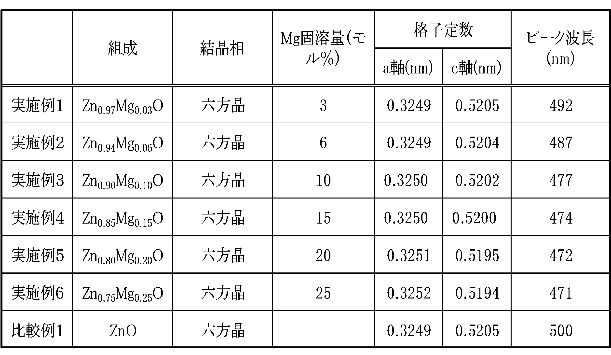
- the magnesium-containing zinc oxide according to Example 1 was powdery. The manufacturing conditions are shown in Table 1. The obtained magnesium-containing zinc oxide was analyzed as follows.
- composition The composition of magnesium-containing zinc oxide was analyzed by ICP emission analysis. The results are shown in Table 2.
- Crystal phase The crystal structure of magnesium-containing zinc oxide was measured by powder X-ray diffraction. The results are shown in Table 2.
- magnesium solid solution amount The magnesium solid solution amount was determined from the crystal phase measurement result (hexagonal crystal formation) and the composition measurement result (Mg content). The results are shown in Table 2.
- the lattice constant was determined by powder X-ray diffraction using Si standard powder as an internal standard. The results are shown in Table 2. The relationship between the lattice constant and the magnesium solid solution amount is shown in FIG.
- the peak wavelength of the PL spectrum of magnesium-containing zinc oxide was measured as follows. First, oxygen defects were introduced into the magnesium-containing zinc oxide powder by reducing the magnesium-containing zinc oxide powder at 800 ° C. for 2 hours in an atmosphere containing 5% by volume of hydrogen gas in argon gas. A blue phosphor powder was obtained. The PL spectrum of this powder was measured with a spectrofluorometer (manufactured by JASCO; FP-6500) at an excitation wavelength of 320 nm. The results are shown in Table 2 and FIG. Moreover, the relationship between the peak wavelength of PL spectrum and the amount of Mg solid solution is shown in FIG.
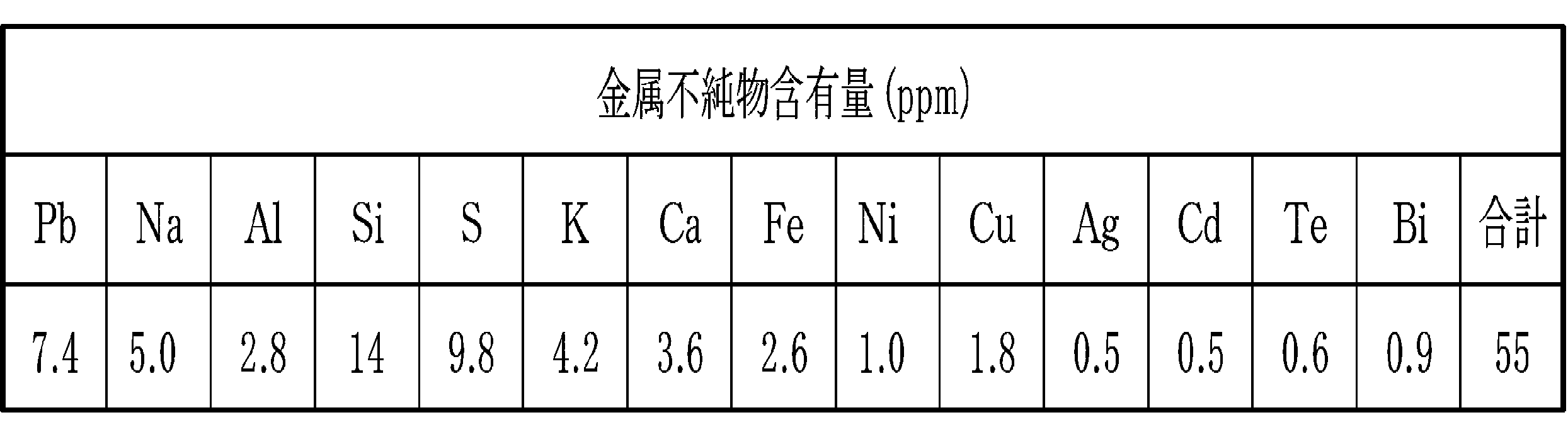
- the metal impurities (Pb, Na, Al, Si, S, K, Ca, Fe, Ni, Cu, Ag, Cd, Te, Bi) of the magnesium-containing zinc oxide were measured by ICP emission analysis.
- the content of metal impurities was 55 ppm, and the purity of magnesium-containing zinc oxide was 99.99% by mass or more. Details of the results of Example 1 are shown in Table 3.
- the magnesium-containing zinc oxide according to Example 1 is composed only of metal zinc and metal magnesium, the obtained magnesium-containing zinc oxide does not contain a halogen component such as fluorine or chlorine.
- Example 2 to 6 Magnesium-containing zinc oxide was obtained in the same manner as in Example 1 except that the conditions described in Table 1 were used. The composition, crystal phase, Mg solid solution amount, lattice constant, and peak wavelength were determined in the same manner as in Example 1, and the results are shown in Table 2. Further, the impurities and the particle size distribution were obtained in the same manner as in Example 1, and the same results were obtained. Since the magnesium-containing zinc oxide according to Examples 2 to 6 is made of only metal zinc and metal magnesium, the obtained magnesium-containing zinc oxide does not contain a halogen component such as fluorine or chlorine.
- a halogen component such as fluorine or chlorine.
- Example 1 Zinc oxide was obtained in the same manner as in Example 1 except that magnesium vapor was not supplied and the conditions described in Table 1 were used. The composition, crystal phase, Mg solid solution amount, lattice constant, and peak wavelength were determined in the same manner as in Example 1, and the results are shown in Table 2.
- the peak wavelength shifts to the short wavelength side as magnesium is dissolved in the range of 25.0 mol% or less, and the zinc oxide blue phosphor It can be seen that is generated.
- the solid solution amount is 10 to 25 mol%
- the peak wavelength shifts to the short wavelength side from 477 to 471 nm, and it can be seen that magnesium-containing zinc oxide suitable as a blue phosphor can be obtained.
- SYMBOLS 10 Magnesium containing zinc oxide manufacturing apparatus 11: Zinc vapor generation part 12: Zinc storage container 14, 18: Heat source 15: Magnesium vapor generation part 16: Magnesium storage container 19: Oxidizing gas contact part 20: Mixed steam injection nozzle 21: Oxidation reaction vessel 22: oxidizing gas supply nozzle
Landscapes
- Chemical & Material Sciences (AREA)
- Engineering & Computer Science (AREA)
- Organic Chemistry (AREA)
- Nanotechnology (AREA)
- Materials Engineering (AREA)
- Inorganic Chemistry (AREA)
- Physics & Mathematics (AREA)
- Composite Materials (AREA)
- Condensed Matter Physics & Semiconductors (AREA)
- General Physics & Mathematics (AREA)
- Crystallography & Structural Chemistry (AREA)
- Inorganic Compounds Of Heavy Metals (AREA)
Abstract
金属亜鉛を加熱して亜鉛蒸気を発生させる亜鉛蒸気発生手段11と、金属マグネシウムを加熱してマグネシウム蒸気を発生させるマグネシウム蒸気発生手段15と、前記亜鉛蒸気と前記マグネシウム蒸気を混合して混合蒸気を生成させる混合蒸気生成手段20と、前記混合蒸気に酸化性ガスを接触させてマグネシウム含有酸化亜鉛を生成させる酸化性ガス接触手段19とを備え、前記混合蒸気中の亜鉛の含有量は、マグネシウムよりも多くなるように調整されているマグネシウム含有酸化亜鉛の製造装置である。
Description
本発明は、青色蛍光体等として用いることができるマグネシウム含有酸化亜鉛の製造方法、及びその製造装置に関する。
酸化亜鉛に酸化マグネシウムを部分固溶させたマグネシウム含有酸化亜鉛は、六方晶ウルツ鉱型の結晶構造をもち、酸素欠陥を導入することにより電子線照射や紫外線励起に対して青色系の発光を示すことが知られている(非特許文献1)。中でも、高濃度にマグネシウムが固溶したマグネシウム含有酸化亜鉛は、発光効率が高く、原料の亜鉛やマグネシウムが資源的に豊富で、かつ無公害であることから、環境にやさしい酸化亜鉛系の青色蛍光体として用いることができる。
このようなマグネシウム含有酸化亜鉛を製造する方法としては、固相反応法、共沈法、及び水熱合成法を挙げることができる。
これらのうち、固相反応法は、酸化亜鉛粉末と酸化マグネシウム粉末を固相で反応させてマグネシウム含有酸化亜鉛を安価かつ大量に製造することができるものの、固相反応でのマグネシウムの固溶限界が約2モル%であるため、Zn0.98Mg0.02Oの組成を超える割合でマグネシウムを反応させても立方晶のMgOが析出し、酸化亜鉛にマグネシウムを高濃度に固溶させることができないという問題がある。
上記問題を解消するための方法としては、固相反応を塩化カリウム等のフラックスの存在下で行うことによってマグネシウムを最大20モル%固溶させる方法がある(非特許文献1)。しかし、この方法では、生成物中に不純物が多く含まれ、フラックス成分の除去が必要になるが困難である。さらに、固相反応法においては、反応温度を1300℃以上の高温にする必要があるため、酸化亜鉛が昇華して均一な組成のマグネシウム含有酸化亜鉛を得ることが難しいという問題がある。また、蛍光体に用いるためには、高純度でかつ粒径が揃って分散性の良い酸化亜鉛粉末であることが必要であるが、固相反応法においては、酸化亜鉛が凝集粒子の状態で生成するので、粒径を揃えるために粉砕工程と分級工程を別途設ける必要があるという問題がある。
一方、共沈法によれば、高濃度にマグネシウムが固溶したマグネシウム含有酸化亜鉛を1000℃以下の低温で製造することができる。例えば、亜鉛及びマグネシウムが溶解した混合水溶液と有機酸成分を混合して有機酸複塩を共沈させ、得られた有機酸複塩を熱分解する方法が知られている(特許文献1,非特許文献2)。
さらに、水熱合成法によれば、高濃度にマグネシウムが固溶したマグネシウム含有酸化亜鉛を低温で製造することができる。例えば、酸化亜鉛やサファイア等の微小基板上にマグネシウム含有酸化亜鉛の層を形成させて粒子とする方法が知られている(特許文献2)。
三重県科学技術振興センター工業研究部 研究報告,32,11-17(2008)
三重県科学技術振興センター工業研究部 研究報告,31,6-10(2007)
しかしながら、共沈法は、共沈速度の違いにより均一な組成のマグネシウム含有酸化亜鉛を得ることが難しく、共沈剤を除去する必要があり、また得られたマグネシウム含有酸化亜鉛が凝集しているなどの問題がある。一方、水熱合成法は、粉砕によって微小基板を製造する必要があり、製造工程が煩雑であることや、水熱合成の本質的な問題である反応速度の遅さなどから、マグネシウム含有酸化亜鉛を安価に大量に製造することが難しく、また得られたマグネシウム含有酸化亜鉛が凝集しているという問題がある。さらに、フラックス法においては、フラックス成分の除去が必要であること、均一な組成のマグネシウム含有亜鉛を得ることが難しいこと、及び粒径をそろえるために粉砕工程と分級工程とを設ける必要があることなどの問題がある。
そこで、本発明は、高純度で不純物が少なく、均一かつマグネシウム含有割合の高いマグネシウム含有酸化亜鉛を効率よく大量に製造できるマグネシウム含有酸化亜鉛の製造方法及びその製造装置を提供することを目的とする。
以上の目的を達成するために、本発明者らは、鋭意研究を重ねた結果、亜鉛蒸気とマグネシウム蒸気とを亜鉛蒸気が過剰な状態で混合し、酸化性ガスと反応させることにより高純度で不純物が少なく、均一なマグネシウム含有酸化亜鉛を効率よく大量に製造できることを見出した。すなわち、本発明は、金属亜鉛を加熱して亜鉛蒸気を発生させる工程と、金属マグネシウムを加熱してマグネシウム蒸気を発生させる工程と、前記亜鉛蒸気と前記マグネシウム蒸気を混合して混合蒸気を生成する工程と、前記混合蒸気に酸化性ガスを接触させてマグネシウム含有酸化亜鉛を生成する工程とを備え、前記混合蒸気中の亜鉛の含有量は、マグネシウムよりも多いことを特徴とするマグネシウム含有酸化亜鉛の製造方法である。
また、本発明は、金属亜鉛を加熱して亜鉛蒸気を発生させる亜鉛蒸気発生手段と、金属マグネシウムを加熱してマグネシウム蒸気を発生させるマグネシウム蒸気発生手段と、前記亜鉛蒸気と前記マグネシウム蒸気を混合して混合蒸気を生成させる混合蒸気生成手段と、前記混合蒸気に酸化性ガスを接触させてマグネシウム含有酸化亜鉛を生成させる酸化性ガス接触手段とを備え、前記混合蒸気中の亜鉛の含有量は、マグネシウムよりも多くなるように調整されていることを特徴とするマグネシウム含有酸化亜鉛の製造装置である。
本発明に係るマグネシウム含有酸化亜鉛の製造方法及びその製造装置において、原料となる金属亜鉛としては、その純度が99.9質量%以上であることが好ましく、例えば、電気亜鉛のような3N(スリーナイン)レベルの純度の金属亜鉛を使用することができる。また、原料となる金属マグネシウムとしては、その純度が99.9質量%以上であることが好ましく、例えば、電解法や熱還元法による3N(スリーナイン)レベルの純度のものを使用することができる。
以上のように、本発明によれば、高純度で不純物が少なく、均一かつマグネシウム含有割合の高いマグネシウム含有酸化亜鉛を効率よく大量に製造できるマグネシウム含有酸化亜鉛の製造方法及びその製造装置を提供することができる。
次に、本発明に係るマグネシウム含有酸化亜鉛の製造装置の実施形態の一例について図面を用いて詳細に説明する。
マグネシウム含有酸化亜鉛製造装置10は、金属亜鉛を加熱して亜鉛蒸気を発生させる亜鉛蒸気発生部11と、亜鉛蒸気発生部11と並列して配置されているマグネシウム蒸気発生部15と、亜鉛蒸気発生部11とマグネシウム蒸気発生部15の上方に配置され亜鉛蒸気とマグネシウム蒸気を混合して混合蒸気を噴出する混合蒸気噴出ノズル20と、混合蒸気噴出ノズル20の上方に配置され、混合蒸気と酸化性ガスとを反応させる酸化性ガス接触部19とを備える。
亜鉛蒸気発生部11は、金属亜鉛が収容された亜鉛収容容器12と、亜鉛収容容器12の上面以外を覆うように配置された熱源14と、亜鉛収容容器12の上面中心部から混合蒸気噴出ノズル20に接続された亜鉛蒸気噴出ノズル24とを備える。
亜鉛収容容器12は、内部に金属亜鉛が収容されており、その形状は特に制限されないが、円柱状のものが好ましい。亜鉛収容容器12の上面の中心より外側には、外部からキャリアガスを亜鉛収容容器12内に導入するためのキャリアガス導入管26が接続されている。熱源14としては、金属亜鉛を蒸気になるまで加熱できるものであれば特に制限はない。例えば、抵抗加熱、フレーム加熱、及び高周波加熱を挙げることができる。亜鉛蒸気発生手段としては、金属亜鉛が収容された亜鉛収容容器と、亜鉛収容容器の上面以外を覆う熱源と、亜鉛蒸気を混合蒸気噴出ノズル内に噴出させる亜鉛蒸気噴出ノズルとを備え、さらにキャリアガスを亜鉛収容容器内に導入するキャリアガス導入管が接続された亜鉛蒸気発生部が好ましく挙げられる。
マグネシウム蒸気発生部15は、金属マグネシウムが収容されたマグネシウム収容容器16と、マグネシウム収容容器16の上面以外を覆うように配置された熱源18と、マグネシウム収容容器16の上面中心部から混合蒸気噴出ノズル20内に延びるマグネシウム蒸気噴出ノズル28とを備える。
マグネシウム収容容器16は、内部に金属マグネシウムが収容されており、その形状は特に制限されないが、円柱状のものが好ましい。マグネシウム収容容器16の上面の中心より外側には、外部からキャリアガスをマグネシウム収容容器16内に導入するためのキャリアガス導入管30が接続されている。熱源18としては、金属マグネシウムを蒸気になるまで加熱できるものであれば特に制限はない。例えば、抵抗加熱、フレーム加熱、及び高周波加熱を挙げることができる。マグネシウム蒸気発生手段としては、金属マグネシウムが収容されたマグネシウム収容容器と、マグネシウム収容容器の上面以外を覆う熱源と、マグネシウム蒸気を混合蒸気噴出ノズル内に噴出させるマグネシウム蒸気噴出ノズルとを備え、さらにキャリアガスをマグネシウム収容容器内に導入するキャリアガス導入管が接続されたマグネシウム蒸気発生部が好ましく挙げられる。
混合蒸気噴出ノズル20は、噴出口が上方に開口している有底円筒形状のノズルであり、底の中心部に亜鉛蒸気噴出ノズル24の噴出口が接続されている。また、混合蒸気噴出ノズル20の底面の中心以外の位置から、上方に向かって、マグネシウム蒸気噴出ノズル28が、その底面の位置から混合蒸気噴出ノズル20内の中心軸の位置まで湾曲してその中心軸方向に沿って、混合蒸気噴出ノズル20内に延在している。マグネシウム蒸気噴出ノズル28は、その直径が混合蒸気噴出ノズル20よりも小さく、混合蒸気噴出ノズル20の開口よりも低い位置で上方を向いて開口している。すなわち、亜鉛蒸気噴出ノズル24及びマグネシウム噴出ノズル28は、混合蒸気噴出ノズル20の噴出口よりも上流側に位置し、噴出された亜鉛蒸気及びマグネシウム蒸気が十分混合するように配設されている。混合蒸気噴出ノズル20には、スワールノズルが接続されていてもよく、スワール翼が備えられていてもよい。混合蒸気生成手段としては、その噴出口が上方に開口し、亜鉛蒸気噴出ノズルの噴出口がその底部に接続され、マグネシウム噴出ノズルがその底部から内部に延在している、前述のような混合蒸気噴出ノズルが好ましく挙げられる。
亜鉛収容容器12の上面及びマグネシウム収容容器16の上面、亜鉛蒸気噴出ノズル24及びマグネシウム蒸気噴出ノズル28、並びに混合蒸気噴出ノズル20は、熱源32により覆われている。熱源32としては、亜鉛及びマグネシウムを沸点以上に加熱できるものであれば特に制限はなく、例えば、抵抗加熱、フレーム加熱、及び高周波加熱を挙げることができる。
酸化性ガス接触部19は、円柱形状の酸化反応容器21と、酸化反応容器21の底面よりも上部の側面であって酸化反応の効率を損なわない位置に酸化性ガス導入手段とを備える。酸化性ガス導入手段としては、例えば、酸化性ガス供給ノズル22等が用いられる。酸化反応容器21の底面中心部には、混合蒸気噴出ノズル20が接続されている。酸化性ガス供給ノズル22は、円周方向に等間隔に2本備えられているが、間隔や本数は何ら制限されるものではない。酸化性ガス供給ノズル22の本数は複数本であることが好ましく、2~4本であることがさらに好ましい。酸化反応容器21の上面の中心部には、マグネシウム含有酸化亜鉛を排出する排出口34が設置されている。酸化性ガス接触手段としては、酸化反応容器と、酸化性ガス導入ノズルとを備えた、前記酸化性ガス接触部が好ましく挙げられる。
次に、本実施形態に係るマグネシウム含有酸化亜鉛製造装置10を用いたマグネシウム含有酸化亜鉛の製造方法について説明する。
まず、亜鉛収容容器12内に収容された金属亜鉛を熱源14によって亜鉛の沸点以上、例えば1000℃以上、好ましくは1000~1200℃に加熱し、亜鉛蒸気を発生させる。同時に、マグネシウム収容容器16内に収容された金属マグネシウムを熱源18によってマグネシウムの沸点以上、例えば1200℃以上、好ましくは1200~1400℃に加熱し、マグネシウム蒸気を発生させる。
発生した亜鉛蒸気は亜鉛蒸気噴出ノズル24へ、マグネシウム蒸気はマグネシウム蒸気噴出ノズル28へ流入する。混合蒸気噴出ノズル20の閉塞防止等のため、アルゴン又はヘリウム等の不活性ガスをキャリアガスとしてキャリアガス導入管26から亜鉛収容容器12内へ、キャリアガス導入管30からマグネシウム収容容器16内へ供給する。キャリアガスは、亜鉛蒸気及びマグネシウム蒸気の温度を低下させないように予め加熱して供給するのが好ましい。例えば、亜鉛収容容器12内に導入するキャリアガスは1000~1200℃、マグネシウム収容容器16に導入するキャリアガスは1200~1400℃に加熱して導入する。
亜鉛蒸気は、亜鉛蒸気噴出ノズル24を通って噴出口から混合蒸気噴出ノズル20に噴出する。マグネシウム蒸気は、マグネシウム蒸気噴出ノズル28を通って噴出口から混合蒸気噴出ノズル20内に噴出する。マグネシウム蒸気噴出ノズル28の噴出口は、混合蒸気噴出ノズル20内に、混合蒸気噴出ノズル20の噴出口よりも下方かつ亜鉛蒸気噴出ノズル24の噴出口よりも上方に位置するため、マグネシウム蒸気は、混合蒸気噴出ノズル20内を流れる亜鉛蒸気内に噴出することになる。したがって、亜鉛蒸気とマグネシウム蒸気とが効率よく混合する。
亜鉛蒸気噴出ノズル24、マグネシウム蒸気噴出ノズル28、及び混合蒸気噴出ノズル20は、熱源32により、1200~1400℃に加熱されているのが好ましい。亜鉛蒸気の温度がマグネシウム蒸気の温度よりも低いため、加熱しない場合は、マグネシウム蒸気が亜鉛蒸気で冷却されて、マグネシウムが偏析し、高濃度にマグネシウムが固溶したマグネシウム含有酸化亜鉛が得られない場合がある。
混合蒸気は、マグネシウムの含有割合(モル比)が0<Mg/(Zn+Mg)≦0.25の範囲であることが好ましい。前記式において、マグネシウムの含有割合が0.05以上であることがさらに好ましく、0.08以上であることが特に好ましく、0.10以上であることが特に好ましく、0.20を超えることが最も好ましい。このようなマグネシウム含有割合にすると、青色蛍光体に適した、特にマグネシウム含有量の高いマグネシウム含有酸化亜鉛が得られる。また、マグネシウム含有割合が0.25以下であることが好ましく、このようなマグネシウム含有割合にすると、マグネシウム含有酸化亜鉛中に立方晶のMgOが混入することを回避することができる。
混合蒸気のマグネシウムの含有割合は、例えば、亜鉛蒸気及びマグネシウム蒸気の供給速度で制御することができる。供給速度は、例えば、熱源14及び熱源18の加熱温度や、キャリアガス供給管26及びキャリアガス供給管30からのキャリアガス供給量により制御することができる。
混合蒸気噴出ノズル20から噴出する亜鉛蒸気とマグネシウム蒸気との混合蒸気は、酸化反応容器21内に流入し、酸化性ガス供給ノズル22から導入される酸化性ガスと接する。酸化性ガスとしては、空気、酸素、及び酸素富化空気を挙げることができる。これによって混合蒸気中のマグネシウムと亜鉛が直ちに酸化されて粉末状のマグネシウム含有酸亜鉛が生成する。粉末の粒径は、原料となる亜鉛蒸気やマグネシウム蒸気の濃度、酸化反応温度、及び酸化反応時間などにより制御することができる。粒径を大きくしたい場合は、例えば、原料となる亜鉛やマグネシウムの蒸発速度を上げ、酸化反応温度を上げ、さらに混合蒸気噴出ノズル20の直径を大きくして気流速度を落として酸化反応時間を長くする。酸化反応の条件は、特に制限されず、気相法による酸化亜鉛の製造で採用される公知の条件を採用することができる。
生成したマグネシウム含有酸化亜鉛は、排出口34からバグフィルタ等の製品捕集器(図示せず)へと導かれて捕集される。このようにして得られたマグネシウム含有酸化亜鉛は、Zn1-xMgxOで表される。ここで、xは、0より大きく0.25以下であることが好ましく、0.05以上0.25以下であることがさらに好ましく、0.08以上0.25以下であることがよりさらに好ましく、0.10以上0.25以下であることが特に好ましく、0.20より大きく0.25以下であることが最も好ましい。xの値は、混合蒸気に含まれるマグネシウムの割合によって調節することができる。捕集されたマグネシウム含有酸化亜鉛の純度は、99.9質量%以上であることが好ましい。本実施形態に係るマグネシウム含有酸化亜鉛の製造方法によれば、マグネシウム含有酸化亜鉛は粒径が揃った粉末として得ることができる。この粉末は、六方晶ウルツ鉱型の結晶構造を有し、還元雰囲気下において加熱処理などして酸素欠陥を導入することにより、マグネシウムが固溶していない還元型の酸化亜鉛(Zn:ZnO)の発光ピーク波長である500nmよりも短波長の発光ピークを示す傾向をもつので、青色蛍光体、特に蛍光表示管や電界放出用の青色蛍光体として用いることができる。
次に、実施例及び比較例を挙げて具体的に説明する。なお、マグネシウム含有酸化亜鉛の製造装置は、図1に概略示されるものを用いた。
〔実施例1〕
亜鉛収容容器12(内径150mm,高さ200mm)内に収容された金属亜鉛(高純度化学研究所製:純度99.9質量%以上)を熱源14により1000℃に加熱し、アルゴンガスを10NL/minでキャリアガス供給管26より供給した。亜鉛蒸気は、0.90kg/hで発生した。同時に、マグネシウム収容容器16(内径150mm,高さ200mm)内に収容された金属マグネシウム(高純度化学研究所製:純度99.9質量%以上)を熱源18により1200℃に加熱し、アルゴンガスを1NL/minでキャリアガス供給管30より供給した。マグネシウム蒸気は、0.01kg/hで発生した。
亜鉛収容容器12(内径150mm,高さ200mm)内に収容された金属亜鉛(高純度化学研究所製:純度99.9質量%以上)を熱源14により1000℃に加熱し、アルゴンガスを10NL/minでキャリアガス供給管26より供給した。亜鉛蒸気は、0.90kg/hで発生した。同時に、マグネシウム収容容器16(内径150mm,高さ200mm)内に収容された金属マグネシウム(高純度化学研究所製:純度99.9質量%以上)を熱源18により1200℃に加熱し、アルゴンガスを1NL/minでキャリアガス供給管30より供給した。マグネシウム蒸気は、0.01kg/hで発生した。
発生した亜鉛蒸気は、亜鉛蒸気噴出ノズル24(内径4mm)を通って混合蒸気噴出ノズル20(内径20mm,長さ50mm)に噴出させ、同時に、発生したマグネシウム蒸気は、マグネシウム蒸気噴出ノズル28(内径4mm,混合蒸気噴出ノズル20内の長さ20mm)から混合蒸気噴出ノズル20内に噴出させた。これにより、亜鉛蒸気とマグネシウム蒸気を混合した。なお、混合蒸気噴出ノズル20内の温度は、マグネシウム収容容器16と同じ温度であった。混合された混合蒸気は、混合蒸気噴出ノズル20から酸化反応容器21内に噴出させた。酸化反応容器21内には、酸化性ガス供給ノズルから100NL/minで空気を供給し、混合蒸気と空気とを接触させ、酸化反応を行った。これにより生成したマグネシウム含有酸化亜鉛は、吸引ファン(図示せず)により、排出口34からバグフィルタ(図示せず)に導いて捕集し、実施例1に係るマグネシウム含有酸化亜鉛を得た。実施例1に係るマグネシウム含有酸化亜鉛は粉末状であった。製造条件を表1に示す。得られたマグネシウム含有酸化亜鉛は、以下のようにして分析した。
(組成)
マグネシウム含有酸化亜鉛の組成は、ICP発光分析により分析した。結果を表2に示す。
マグネシウム含有酸化亜鉛の組成は、ICP発光分析により分析した。結果を表2に示す。
(結晶相)
マグネシウム含有酸化亜鉛の結晶構造は、粉末X線回折により測定した。結果を表2に示す。
マグネシウム含有酸化亜鉛の結晶構造は、粉末X線回折により測定した。結果を表2に示す。
(Mg固溶量)
結晶相の測定結果(六方晶生成)及び組成の測定結果(Mg含有量)よりマグネシウム固溶量を求めた。結果を表2に示す。
結晶相の測定結果(六方晶生成)及び組成の測定結果(Mg含有量)よりマグネシウム固溶量を求めた。結果を表2に示す。
(格子定数)
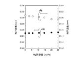
Si標準粉末を内部標準とした粉末X線回折より格子定数を求めた。結果を表2に示す。また、格子定数とマグネシウム固溶量との関係を図2に示す。
Si標準粉末を内部標準とした粉末X線回折より格子定数を求めた。結果を表2に示す。また、格子定数とマグネシウム固溶量との関係を図2に示す。
(ピーク波長)
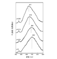
マグネシウム含有酸化亜鉛のPLスペクトルのピーク波長を、次のように測定した。まず、マグネシウム含有酸化亜鉛の粉末を、アルゴンガスに水素ガスを5体積%含有させた雰囲気中で、800℃で2時間、還元処理することにより、マグネシウム含有酸化亜鉛の粉末に酸素欠陥を導入し、青色蛍光体粉末とした。この粉末のPLスペクトルを分光蛍光光度計(日本分光製;FP-6500)により、励起波長320nmで測定した。結果を表2及び図3に示す。また、PLスペクトルのピーク波長とMg固溶量との関係を図4に示す。
マグネシウム含有酸化亜鉛のPLスペクトルのピーク波長を、次のように測定した。まず、マグネシウム含有酸化亜鉛の粉末を、アルゴンガスに水素ガスを5体積%含有させた雰囲気中で、800℃で2時間、還元処理することにより、マグネシウム含有酸化亜鉛の粉末に酸素欠陥を導入し、青色蛍光体粉末とした。この粉末のPLスペクトルを分光蛍光光度計(日本分光製;FP-6500)により、励起波長320nmで測定した。結果を表2及び図3に示す。また、PLスペクトルのピーク波長とMg固溶量との関係を図4に示す。
(不純物)
マグネシウム含有酸化亜鉛の金属不純物(Pb,Na,Al,Si,S,K,Ca,Fe,Ni,Cu,Ag,Cd,Te,Bi)は、ICP発光分析により測定した。金属不純物の含有量は55ppm、マグネシウム含有酸化亜鉛の純度は99.99質量%以上であった。実施例1の結果の詳細を表3に示す。
マグネシウム含有酸化亜鉛の金属不純物(Pb,Na,Al,Si,S,K,Ca,Fe,Ni,Cu,Ag,Cd,Te,Bi)は、ICP発光分析により測定した。金属不純物の含有量は55ppm、マグネシウム含有酸化亜鉛の純度は99.99質量%以上であった。実施例1の結果の詳細を表3に示す。
(粒度分布)
マグネシウム含有酸化亜鉛の粒度分布は、レーザー回折散乱法(堀場製作所製;LA-910)により測定した。結果は、図5に示すように単分散でシャープな粒度分布であった。
マグネシウム含有酸化亜鉛の粒度分布は、レーザー回折散乱法(堀場製作所製;LA-910)により測定した。結果は、図5に示すように単分散でシャープな粒度分布であった。

実施例1に係るマグネシウム含有酸化亜鉛は、原料が金属亜鉛と金属マグネシウムのみであることから、得られるマグネシウム含有酸化亜鉛はフッ素や塩素等のハロゲン成分を含んでいない。
〔実施例2~6〕
表1に記載されている条件とした以外は、実施例1と同様の方法でマグネシウム含有酸化亜鉛を得た。組成、結晶相、Mg固溶量、格子定数、及びピーク波長については、実施例1と同様にして求め、同様に結果を表2に示した。また、不純物と粒度分布についても実施例1と同様にして求め、同様の結果が得られた。実施例2乃至6に係るマグネシウム含有酸化亜鉛は、原料が金属亜鉛と金属マグネシウムのみであることから、得られるマグネシウム含有酸化亜鉛はフッ素や塩素等のハロゲン成分を含んでいない。
表1に記載されている条件とした以外は、実施例1と同様の方法でマグネシウム含有酸化亜鉛を得た。組成、結晶相、Mg固溶量、格子定数、及びピーク波長については、実施例1と同様にして求め、同様に結果を表2に示した。また、不純物と粒度分布についても実施例1と同様にして求め、同様の結果が得られた。実施例2乃至6に係るマグネシウム含有酸化亜鉛は、原料が金属亜鉛と金属マグネシウムのみであることから、得られるマグネシウム含有酸化亜鉛はフッ素や塩素等のハロゲン成分を含んでいない。
〔比較例1〕
マグネシウム蒸気を供給せず、表1に記載されている条件とした以外は、実施例1と同様の方法で酸化亜鉛を得た。組成、結晶相、Mg固溶量、格子定数、及びピーク波長については、実施例1と同様にして求め、同様に結果を表2に示した。
マグネシウム蒸気を供給せず、表1に記載されている条件とした以外は、実施例1と同様の方法で酸化亜鉛を得た。組成、結晶相、Mg固溶量、格子定数、及びピーク波長については、実施例1と同様にして求め、同様に結果を表2に示した。
実施例1乃至6から、結晶相としては、六方晶ウルツ鉱型構造を持つZnO型固溶体に相当する回折ピーク以外は認められなかったことから、高純度のマグネシウム含有酸化亜鉛が得られたことが分かる。また、レーザー回折散乱法により測定した粒度分布(図5)がシャープであったことから、粒径の揃った均一なマグネシウム含有酸化亜鉛が得られることが分かる。さらに、格子定数とマグネシウム固溶量との関係(図2)から、a軸はマグネシウム固溶量による変化が見られなかったが、c軸はマグネシウム固溶量の増加に伴って格子定数の減少が見られた。すなわち、マグネシウムが酸化亜鉛に連続的に固溶していることが分かる。さらに、ピーク波長とMg固溶量との関係(図4)から、25.0モル%以下の範囲でマグネシウムが固溶するに従ってピーク波長が短波長側にシフトし、酸化亜鉛系の青色蛍光体が生成していることが分かる。特に、固溶量が10~25モル%の場合、ピーク波長は477~471nmまで短波長側にシフトし、青色蛍光体として適したマグネシウム含有酸化亜鉛が得られることが分かる。
10:マグネシウム含有酸化亜鉛製造装置
11:亜鉛蒸気発生部
12:亜鉛収容容器
14,18:熱源
15:マグネシウム蒸気発生部
16:マグネシウム収容容器
19:酸化性ガス接触部
20:混合蒸気噴出ノズル
21:酸化反応容器
22:酸化性ガス供給ノズル
11:亜鉛蒸気発生部
12:亜鉛収容容器
14,18:熱源
15:マグネシウム蒸気発生部
16:マグネシウム収容容器
19:酸化性ガス接触部
20:混合蒸気噴出ノズル
21:酸化反応容器
22:酸化性ガス供給ノズル
Claims (10)
- 金属亜鉛を加熱して亜鉛蒸気を発生させる工程と、
金属マグネシウムを加熱してマグネシウム蒸気を発生させる工程と、
前記亜鉛蒸気と前記マグネシウム蒸気を混合して混合蒸気を生成する工程と、
前記混合蒸気に酸化性ガスを接触させてマグネシウム含有酸化亜鉛を生成する工程とを備え、
前記混合蒸気中の亜鉛の含有量は、マグネシウムよりも多いことを特徴とするマグネシウム含有酸化亜鉛の製造方法。 - 前記混合蒸気のマグネシウムの含有割合(モル比)が0<Mg/(Zn+Mg)≦0.25の範囲であることを特徴とする請求項1記載のマグネシウム含有酸化亜鉛の製造方法。
- 前記混合蒸気のマグネシウムの含有割合(モル比)が0.05≦Mg/(Zn+Mg)≦0.25の範囲であることを特徴とする請求項1記載のマグネシウム含有酸化亜鉛の製造方法。
- 請求項1乃至3いずれか記載の製造方法により製造されたマグネシウム含有酸化亜鉛であって、前記マグネシウム含有酸化亜鉛がZn1-xMgxO(0<x≦0.25)であることを特徴とするマグネシウム含有酸化亜鉛。
- 金属亜鉛を加熱して亜鉛蒸気を発生させる亜鉛蒸気発生手段と、
金属マグネシウムを加熱してマグネシウム蒸気を発生させるマグネシウム蒸気発生手段と、
前記亜鉛蒸気と前記マグネシウム蒸気を混合して混合蒸気を生成させる混合蒸気生成手段と、
前記混合蒸気に酸化性ガスを接触させてマグネシウム含有酸化亜鉛を生成させる酸化性ガス接触手段とを備え、
前記混合蒸気中の亜鉛の含有量は、マグネシウムよりも多くなるように調整されていることを特徴とするマグネシウム含有酸化亜鉛の製造装置。 - 前記酸化性ガス接触手段は、酸化反応容器と、該酸化反応容器内に前記酸化性ガスを導入する酸化性ガス導入手段とを備え、
前記混合蒸気生成手段は、生成した混合蒸気を前記酸化反応容器内に導入される酸化性ガスと接触させるように、前記混合蒸気を前記酸化反応容器内に噴出させる混合蒸気噴出ノズルを備えていることを特徴とする請求項5記載のマグネシウム含有酸化亜鉛の製造装置。 - 前記亜鉛蒸気発生手段は、発生させた亜鉛蒸気を前記混合蒸気噴出ノズル内に噴出させる亜鉛蒸気噴出ノズルを備え、
前記マグネシウム蒸気発生手段は、発生させたマグネシウム蒸気を前記混合蒸気噴出ノズル内に噴出させるマグネシウム蒸気噴出ノズルを備え、
前記亜鉛蒸気噴出ノズル及びマグネシウム蒸気噴出ノズルの噴出口は、噴出された亜鉛蒸気及びマグネシウム蒸気が十分に混合するように、前記混合蒸気噴出ノズルの噴出口よりも上流側に位置することを特徴とする請求項6記載のマグネシウム含有酸化亜鉛の製造装置。 - 前記マグネシウム蒸気噴出ノズルの噴出口は、混合蒸気噴出ノズル内を流動する亜鉛蒸気に囲まれた状態でマグネシウム蒸気を噴出させるように構成されていることを特徴とする請求項7記載のマグネシウム含有酸化亜鉛の製造装置。
- 前記亜鉛蒸気噴出ノズルの噴出口は、前記マグネシウム蒸気噴出ノズルよりも上流側に位置することを特徴とする請求項7又は8記載のマグネシウム含有酸化亜鉛の製造装置。
- 前記亜鉛蒸気噴出ノズルと、マグネシウム蒸気噴出ノズルと、前記混合蒸気噴出ノズルとを加熱する熱源をさらに備えたことを特徴とする請求項7乃至9いずれか記載のマグネシウム含有酸化亜鉛の製造装置。
Priority Applications (4)
| Application Number | Priority Date | Filing Date | Title |
|---|---|---|---|
| EP10786127.0A EP2441734A4 (en) | 2009-06-12 | 2010-06-04 | PROCESS FOR PRODUCING ZINC OXIDE CONTAINING MAGNESIUM, ZINC OXIDE CONTAINING MAGNESIUM AND PRODUCTION APPARATUS |
| JP2011518516A JP5644763B2 (ja) | 2009-06-12 | 2010-06-04 | マグネシウム含有酸化亜鉛の製造方法及びマグネシウム含有酸化亜鉛の製造装置 |
| US13/377,074 US8388928B2 (en) | 2009-06-12 | 2010-06-04 | Method for producing magnesium-containing zinc oxide, magnesium-containing zinc oxide, and apparatus for producing same |
| US13/758,672 US20130149534A1 (en) | 2009-06-12 | 2013-02-04 | Method for Producing Magnesium-Containing Zinc Oxide, Magnesium-Containing Zinc Oxide, and Apparatus for Producing Same |
Applications Claiming Priority (2)
| Application Number | Priority Date | Filing Date | Title |
|---|---|---|---|
| JP2009141588 | 2009-06-12 | ||
| JP2009-141588 | 2009-06-12 |
Related Child Applications (1)
| Application Number | Title | Priority Date | Filing Date |
|---|---|---|---|
| US13/758,672 Division US20130149534A1 (en) | 2009-06-12 | 2013-02-04 | Method for Producing Magnesium-Containing Zinc Oxide, Magnesium-Containing Zinc Oxide, and Apparatus for Producing Same |
Publications (1)
| Publication Number | Publication Date |
|---|---|
| WO2010143596A1 true WO2010143596A1 (ja) | 2010-12-16 |
Family
ID=43308851
Family Applications (1)
| Application Number | Title | Priority Date | Filing Date |
|---|---|---|---|
| PCT/JP2010/059550 Ceased WO2010143596A1 (ja) | 2009-06-12 | 2010-06-04 | マグネシウム含有酸化亜鉛の製造方法、マグネシウム含有酸化亜鉛、及びその製造装置 |
Country Status (5)
| Country | Link |
|---|---|
| US (2) | US8388928B2 (ja) |
| EP (1) | EP2441734A4 (ja) |
| JP (1) | JP5644763B2 (ja) |
| TW (1) | TW201105586A (ja) |
| WO (1) | WO2010143596A1 (ja) |
Families Citing this family (2)
| Publication number | Priority date | Publication date | Assignee | Title |
|---|---|---|---|---|
| CA2796441C (en) * | 2010-04-26 | 2017-12-12 | Sakai Chemical Industry Co., Ltd. | Filler particles, resin composition, grease, and coating composition |
| CN119909613A (zh) * | 2025-04-01 | 2025-05-02 | 西安慧金科技有限公司 | 一种大型氧化亚硅预镁或锂负极材料制备设备及方法 |
Citations (5)
| Publication number | Priority date | Publication date | Assignee | Title |
|---|---|---|---|---|
| JPS61122106A (ja) * | 1984-11-19 | 1986-06-10 | Ube Ind Ltd | 微粉末状マグネシウム酸化物の製造方法 |
| JP2004182519A (ja) * | 2002-12-02 | 2004-07-02 | Ube Material Industries Ltd | 金属マグネシウム溶融蒸発装置、及びこれを用いた高純度酸化マグネシウム微粉末の製造方法 |
| JP2006233047A (ja) | 2005-02-25 | 2006-09-07 | Mie Prefecture | 青色系蛍光体用酸化亜鉛系固溶体及びその製造方法並びに青色系蛍光体及びその製造方法 |
| JP2006335914A (ja) | 2005-06-03 | 2006-12-14 | Sumitomo Electric Ind Ltd | 粉末蛍光体とその製法、およびこれを用いた発光デバイス |
| WO2007144242A2 (en) * | 2006-06-13 | 2007-12-21 | Evonik Degussa Gmbh | Process for preparing metal oxide powders |
Family Cites Families (2)
| Publication number | Priority date | Publication date | Assignee | Title |
|---|---|---|---|---|
| US6716479B2 (en) * | 2002-01-04 | 2004-04-06 | Rutgers, The State University Of New Jersey | Tailoring piezoelectric properties using MgxZn1-xO/ZnO material and MgxZn1-xO/ZnO structures |
| JP2010512664A (ja) * | 2006-12-11 | 2010-04-22 | ルーメンツ リミテッド ライアビリティ カンパニー | 酸化亜鉛多接合光電池及び光電子装置 |
-
2010
- 2010-06-04 EP EP10786127.0A patent/EP2441734A4/en not_active Withdrawn
- 2010-06-04 US US13/377,074 patent/US8388928B2/en not_active Expired - Fee Related
- 2010-06-04 WO PCT/JP2010/059550 patent/WO2010143596A1/ja not_active Ceased
- 2010-06-04 JP JP2011518516A patent/JP5644763B2/ja not_active Expired - Fee Related
- 2010-06-09 TW TW099118675A patent/TW201105586A/zh unknown
-
2013
- 2013-02-04 US US13/758,672 patent/US20130149534A1/en not_active Abandoned
Patent Citations (5)
| Publication number | Priority date | Publication date | Assignee | Title |
|---|---|---|---|---|
| JPS61122106A (ja) * | 1984-11-19 | 1986-06-10 | Ube Ind Ltd | 微粉末状マグネシウム酸化物の製造方法 |
| JP2004182519A (ja) * | 2002-12-02 | 2004-07-02 | Ube Material Industries Ltd | 金属マグネシウム溶融蒸発装置、及びこれを用いた高純度酸化マグネシウム微粉末の製造方法 |
| JP2006233047A (ja) | 2005-02-25 | 2006-09-07 | Mie Prefecture | 青色系蛍光体用酸化亜鉛系固溶体及びその製造方法並びに青色系蛍光体及びその製造方法 |
| JP2006335914A (ja) | 2005-06-03 | 2006-12-14 | Sumitomo Electric Ind Ltd | 粉末蛍光体とその製法、およびこれを用いた発光デバイス |
| WO2007144242A2 (en) * | 2006-06-13 | 2007-12-21 | Evonik Degussa Gmbh | Process for preparing metal oxide powders |
Non-Patent Citations (5)
| Title |
|---|
| G.NING ET AL.: "Structure and optical properties of MgXZn1-XO nanoparticles prepared by sol-gel method", OPTICAL MATERIALS, vol. 27, no. 1, 11 March 2004 (2004-03-11), pages 1 - 5, XP004568553 * |
| MIE PREFECTURAL INDUSTRIAL RESEARCH INSTITUTE, STUDY REPORT, vol. 31, 2007, pages 6 - 10 |
| MIE PREFECTURAL INDUSTRIAL RESEARCH INSTITUTE, STUDY REPORT, vol. 32, 2008, pages 11 - 17 |
| S.OHSHIRO ET AL.: "Low-temperature Synthesis of Nanometer-sized Single Crystals in MgO-ZnO Solid Solution", JOURNAL OF THE JAPAN SOCIETY OF COLOUR MATERIAL, vol. 75, no. 7, 20 July 2002 (2002-07-20), pages 327 - 329, XP008150407 * |
| See also references of EP2441734A4 |
Also Published As
| Publication number | Publication date |
|---|---|
| US20120104318A1 (en) | 2012-05-03 |
| EP2441734A4 (en) | 2013-08-28 |
| EP2441734A1 (en) | 2012-04-18 |
| US8388928B2 (en) | 2013-03-05 |
| JPWO2010143596A1 (ja) | 2012-11-22 |
| US20130149534A1 (en) | 2013-06-13 |
| TW201105586A (en) | 2011-02-16 |
| JP5644763B2 (ja) | 2014-12-24 |
Similar Documents
| Publication | Publication Date | Title |
|---|---|---|
| US10189003B1 (en) | Continuous microwave-assisted segmented flow reactor for high-quality nanocrystal synthesis | |
| JP3383608B2 (ja) | ナノ結晶性材料を合成するための装置 | |
| US6689191B2 (en) | Rapid conversion of metal-containing compounds to form metals or metal alloys | |
| JP5343697B2 (ja) | 複合タングステン酸化物超微粒子の製造方法 | |
| JP2005289798A (ja) | 二酸化チタンナノパウダーの製造方法 | |
| AU2001243276A1 (en) | Rapid conversion of metal-containing compounds to form metals or metal oxides | |
| Hassan et al. | Synthesis of ZnO nanoparticles by a hybrid electrochemical-thermal method: influence of calcination temperature | |
| JP7116415B2 (ja) | 複合タングステン酸化物粒子の製造方法 | |
| CN101679860B (zh) | 氧化物发光体 | |
| CN103964475B (zh) | 立方体状氧化镁粉末及其制法 | |
| Soltani et al. | Comparison of benzene and toluene photodegradation under visible light irradiation by Ba-doped BiFeO3 magnetic nanoparticles with fast sonochemical synthesis | |
| JP5644763B2 (ja) | マグネシウム含有酸化亜鉛の製造方法及びマグネシウム含有酸化亜鉛の製造装置 | |
| Chen et al. | An effective approach to grow boron nitride nanowires directly on stainless-steel substrates | |
| JP2004124257A (ja) | 金属銅微粒子及びその製造方法 | |
| US8512673B2 (en) | Magnesium oxide powder of high purity | |
| JP7302808B2 (ja) | 複合タングステン酸化物粒子の製造方法 | |
| KR20220016841A (ko) | 미립자의 제조 장치 및 미립자의 제조 방법 | |
| Ishigaki | Synthesis of ceramic nanoparticles with non-equilibrium crystal structures and chemical compositions by controlled thermal plasma processing | |
| KR101036484B1 (ko) | 플라즈마 제트를 이용한 산화아연 나노막대의 제조방법 및 이에 의해 제조된 산화아연 나노막대의 광촉매 활성 | |
| WO2021100320A1 (ja) | 微粒子 | |
| RU2738596C1 (ru) | Способ получения ультрадисперсных частиц однородных оксидных керамических композиций, состоящих из ядра и внешних оболочек | |
| Hong et al. | The Effect of flux types on the formation of green light emitting phosphor particles with spherical shape and filled morphology | |
| Samokhin et al. | Characteristics of heat and mass transfer to the wall of a confined-jet plasma flow reactor in the processes of nanopowder preparation from metals and their compounds | |
| Ledoux et al. | Host size effects on optical properties of Y2O3: Eu3+ and Gd2O3: Eu3+ nanoparticles synthesized by laser pyrolysis | |
| JP2001220581A (ja) | 蛍光体粒子の製造方法 |
Legal Events
| Date | Code | Title | Description |
|---|---|---|---|
| 121 | Ep: the epo has been informed by wipo that ep was designated in this application |
Ref document number: 10786127 Country of ref document: EP Kind code of ref document: A1 |
|
| WWE | Wipo information: entry into national phase |
Ref document number: 2011518516 Country of ref document: JP |
|
| NENP | Non-entry into the national phase |
Ref country code: DE |
|
| WWE | Wipo information: entry into national phase |
Ref document number: 2010786127 Country of ref document: EP |
|
| WWE | Wipo information: entry into national phase |
Ref document number: 13377074 Country of ref document: US |