WO2010143624A1 - Bouchon perméable à l'air et procédé d'inspection de bouchon perméable à l'air - Google Patents
Bouchon perméable à l'air et procédé d'inspection de bouchon perméable à l'air Download PDFInfo
- Publication number
- WO2010143624A1 WO2010143624A1 PCT/JP2010/059687 JP2010059687W WO2010143624A1 WO 2010143624 A1 WO2010143624 A1 WO 2010143624A1 JP 2010059687 W JP2010059687 W JP 2010059687W WO 2010143624 A1 WO2010143624 A1 WO 2010143624A1
- Authority
- WO
- WIPO (PCT)
- Prior art keywords
- vent plug
- vent
- permeable membrane
- gas permeable
- cylindrical member
- Prior art date
- Legal status (The legal status is an assumption and is not a legal conclusion. Google has not performed a legal analysis and makes no representation as to the accuracy of the status listed.)
- Ceased
Links
Images


Classifications
-
- B—PERFORMING OPERATIONS; TRANSPORTING
- B65—CONVEYING; PACKING; STORING; HANDLING THIN OR FILAMENTARY MATERIAL
- B65D—CONTAINERS FOR STORAGE OR TRANSPORT OF ARTICLES OR MATERIALS, e.g. BAGS, BARRELS, BOTTLES, BOXES, CANS, CARTONS, CRATES, DRUMS, JARS, TANKS, HOPPERS, FORWARDING CONTAINERS; ACCESSORIES, CLOSURES, OR FITTINGS THEREFOR; PACKAGING ELEMENTS; PACKAGES
- B65D51/00—Closures not otherwise provided for
- B65D51/16—Closures not otherwise provided for with means for venting air or gas
- B65D51/1605—Closures not otherwise provided for with means for venting air or gas whereby the interior of the container is maintained in permanent gaseous communication with the exterior
- B65D51/1616—Closures not otherwise provided for with means for venting air or gas whereby the interior of the container is maintained in permanent gaseous communication with the exterior by means of a filter
-
- H—ELECTRICITY
- H05—ELECTRIC TECHNIQUES NOT OTHERWISE PROVIDED FOR
- H05K—PRINTED CIRCUITS; CASINGS OR CONSTRUCTIONAL DETAILS OF ELECTRIC APPARATUS; MANUFACTURE OF ASSEMBLAGES OF ELECTRICAL COMPONENTS
- H05K5/00—Casings, cabinets or drawers for electric apparatus
- H05K5/02—Details
- H05K5/0213—Venting apertures; Constructional details thereof
- H05K5/0216—Venting plugs comprising semi-permeable membranes
-
- F—MECHANICAL ENGINEERING; LIGHTING; HEATING; WEAPONS; BLASTING
- F21—LIGHTING
- F21S—NON-PORTABLE LIGHTING DEVICES; SYSTEMS THEREOF; VEHICLE LIGHTING DEVICES SPECIALLY ADAPTED FOR VEHICLE EXTERIORS
- F21S45/00—Arrangements within vehicle lighting devices specially adapted for vehicle exteriors, for purposes other than emission or distribution of light
- F21S45/30—Ventilation or drainage of lighting devices
Definitions
- the present invention relates to a vent plug provided with a vent film having a function of blocking liquid such as water droplets and oil droplets while allowing gas to pass through, and a method for inspecting the vent plug.
- Patent Documents 1 to 3 disclose a vent plug that allows gas to enter and exit while preventing intrusion of liquid such as water droplets by forming a drip-proof vent film at one end of a cylindrical member. Are listed. Further, it is described that the vent plug is suitably used for electric devices such as a motor case.
- JP 2001-143524 A (FIG. 1) JP 2003-63549 A (FIGS. 1 and 2) JP 2008-148388 A (FIGS. 4 and 5)
- the vent membrane When the conventional vent plug is used, when the vent plug is handled, for example, when the vent plug is mounted on the motor case, the operator's fingers and attachment devices (hereinafter referred to as “finger fingers”) are used as the vent membrane. There was a case where it was damaged by contact. Under such circumstances, the applicant has so far studied a structure for making it difficult for fingers and the like to come into direct contact with the gas permeable membrane.
- the ventilation film 2 is not formed on the end surface of the cylindrical member 1, but is vented into the cylindrical member 1 at a position slightly inward from the end of the cylindrical member 1.
- a structure for sandwiching the film 2 has been studied. With such a configuration, the end portion of the cylindrical member 1 has a structure that protrudes upward from the plane including the gas permeable membrane 2, so that the end surface of the cylindrical member 1 functions as a protective bank against fingers and the like. The probability that a finger etc. will contact 2 directly can be reduced.
- an object of the present invention is to provide a vent plug that can easily identify whether or not the gas permeable membrane 2 is properly sandwiched inside the cylindrical member 1 by observing the appearance.
- vent plug of the present invention capable of achieving the above-mentioned object is A vent plug comprising a tubular member having a through hole and a gas permeable membrane crossing the through hole, wherein a peripheral portion of the gas permeable membrane is sandwiched between the cylindrical members, and on the side surface of the cylindrical member The opening part which can visually recognize the peripheral edge part of the said air permeable membrane is formed.
- the hues of the tubular member and the gas permeable membrane are separated from each other by 15 ° or more when the entire circumference of the hue ring, which is a measure of hue, is 360 °.
- the tubular member and the gas permeable membrane differ in brightness by 1 degree or more.
- the cylindrical member and the gas permeable membrane differ in saturation by 2 degrees or more.
- the opening may be formed over the entire circumference of the side surface of the cylindrical member.
- the vent film and / or the cylindrical member contain one or more of a phosphorescent agent, a fluorescent agent, and a light reflecting material.
- the cylindrical member has a concavo-convex shape on a surface sandwiching a peripheral portion of the vent film.
- vent plug it is preferable that at least two annular convex portions are formed on the side surface of the cylindrical member with the opening interposed therebetween.
- the non-opening portion between adjacent openings is 90 ° or less. Is desirable.
- a reinforcing film is formed on one side or both sides of the vent film.
- vent film has liquid repellency.
- peripheral edge portion of the gas permeable membrane visually recognized from the opening portion also has liquid repellency.
- the gas permeable membrane is composed of a porous polytetrafluoroethylene membrane.
- a desirable inspection method for the vent plug includes a step of photographing a side image of the vent plug and a step of determining whether or not the vent film is appropriately fixed from the side image.
- the peripheral portion of the gas permeable membrane is sandwiched by the cylindrical member, and a predetermined opening that allows the peripheral edge portion of the gas permeable membrane to be visually recognized is formed on the side surface of the cylindrical member. Since the inside of the cylindrical member can be visually recognized through the opening, it can be determined that the gas permeable membrane is appropriately held.
- Embodiment 1 of the present invention It is an external view of the vent plug concerning Embodiment 1 of the present invention. It is a side view of the vent plug. It is sectional drawing of the vent plug. It is an external view of the vent plug concerning Embodiment 2 of the present invention. It is an external view of the vent plug concerning Embodiment 3 of the present invention. It is an external view of the vent plug concerning Embodiment 4 of the present invention.
- A) is a top view of the vent plug according to Embodiment 5 of the present invention, and (b) is a side view of the vent plug.
- A) is a top view of the vent plug according to Embodiment 6 of the present invention, and (b) is a side view of the vent plug.
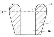
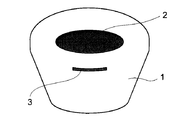
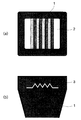
- FIG. 1 is an external view of a vent plug according to Embodiment 1 of the present invention
- FIG. 2 is a side view of the vent plug
- FIG. 3 is a cross-sectional view of the vent plug. 1 to 3
- a tubular plug 1 having a through hole 1a and a vent film 2 crossing the through hole 1a constitute a vent plug.
- the peripheral part of the gas permeable membrane 2 is sandwiched between the cylindrical members 1, and an opening 3 is formed on the side surface of the cylindrical member 1 so that the peripheral edge of the gas permeable film 2 can be visually recognized.
- the presence state of the peripheral edge of the gas permeable membrane 2 can be grasped through the opening 3. For example, if the presence of the peripheral edge of the gas permeable membrane 2 is confirmed in the opening 3, it is determined that the gas permeable membrane 2 is appropriately fixed at a predetermined position. On the other hand, if the presence of the gas permeable membrane 2 is not confirmed in the opening 3, it can be determined that the gas permeable membrane 2 is not arranged at a predetermined position as in the example shown in FIG. 14 or FIG. . The vent plug thus determined is discarded as a defective product.
- the inspection of the gas permeable membrane 2 can be performed visually, but can also be automated. You may employ
- inspection method of a vent plug including the process of image
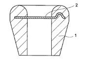
- FIG. 4 is an external view of a vent plug according to Embodiment 2 of the present invention.
- the color of the tubular member 1 and the vent film 2 is different from the vent plug according to the first embodiment.
- the tubular member 1 has a color close to black
- the vent film 2 has a color close to white. Therefore, the contrast between the tubular member 1 and the vent film 2 is high. It ’s good.
- the tubular member 1 has a color close to white
- the vent film 2 has a color close to black, and similarly has good contrast.
- the gist of the present invention is to confirm the presence of the gas permeable membrane 2 through the opening 3 of the tubular member 1 as described above. Therefore, it is more preferable that the difference in appearance between the tubular member 1 and the gas permeable membrane 2 is large. Various factors such as color differences due to material differences, light reflectance differences, surface roughness differences, texture differences, etc. can be considered as factors that cause differences in appearance. Is preferable for identification.
- colors have three elements: hue, brightness, and saturation. In the present embodiment, it is defined for each of the three elements whether a color difference between the tubular member 1 and the gas permeable membrane 2 is preferable for identifying the gas permeable membrane 2.
- the hue H can be specified using a hue circle.
- the hue circle is an arrangement in which the total hue is divided and arranged in an annular shape so that the difference in hue perception is approximately equal.
- complementary colors are provided at opposite positions.
- the color wheel is theoretically continuous and continuous.
- the hue circle is expressed in 30 divisions.
- what is expressed in 24 divisions (Nippon Color Research Co., Ltd. hue ring) is also known.
- the difference in hue H is indicated by the angle between the two colors when the entire circumference of the hue circle is 360 °.
- the hue difference between the tubular member 1 and the gas permeable membrane 2 is preferably 15 ° or more.
- the angle of 15 ° is an angle representing the interval between adjacent hues in the hue circle obtained by dividing the entire circumference of 360 ° into 24 parts. More preferably, it is 30 ° or more.
- Lightness (V) Among the attributes of color perception, the lightness V is divided so that the ideal black is 0 degrees and the ideal white is 10 degrees on the basis of the achromatic color, and the difference in lightness perception is approximately equal.
- the intermediate brightness V belonging to this range is expressed by 1 to 9 degrees (see 3.2 “Lightness Display Method” of JIS Z1821).
- the lightness difference between the tubular member 1 and the gas permeable membrane 2 is preferably 1 degree or more. More preferably, it is 2 degrees or more.
- JIS Z1821 6 (2) “Method determined from direct comparison with standard color standard” can be used.
- saturation C indicates the degree of chromatic color
- achromatic color is set to 0, and is sequentially expressed as 1, 2, 3, 4 in accordance with a constant increase in the degree of saturation.
- the saturation difference between the tubular member 1 and the gas permeable membrane 2 is preferably 2 degrees or more. More preferably, it is 3 degrees or more.
- JIS Z1821 6 (2) “Method determined from direct comparison with standard color standard” can be used.
- a method of adding a light emitting material is used in order to improve the distinguishability between the tubular member 1 and the gas permeable membrane 2. Also good.
- a luminescent material one or more of a phosphorescent agent, a fluorescent agent, and a light reflecting material can be added to one or both of the tubular member 1 and the gas permeable membrane 2.
- the luminous agent for example, zinc sulfide activated copper or aluminum oxide or strontium oxide crystallized is used.
- fluorescent agents zinc sulfide phosphors, halophosphate phosphors and the like are typically known.
- the light reflecting material for example, metal particles such as platinum, gold, silver, and aluminum, glass particles such as borosilicate and soda lime, mineral particles such as mica particles, and the like can be used.
- FIG. 5 is an external view of a vent plug according to Embodiment 3 of the present invention. Basically, it is the same as the vent plug according to the first embodiment, but in the third embodiment, four openings 3 are provided (of which the opening shown in FIG. Two openings 3a and 3b). Furthermore, in Embodiment 3, when the whole side surface circumference of the cylindrical member 1 is set to 360 °, all the non-opening portions between adjacent opening portions are designed to be 90 ° or less. That is, as shown in FIG. 5, the non-opening portion between the opening 3a and the opening 3b is designed to have an expansion angle ⁇ (90 ° or less) when viewed from the central axis of the tubular member 1. Yes.
- ⁇ 90 ° or less
- the case where the number of the opening portions 3 is four has been described. However, it can be appropriately adjusted depending on the extension range of the opening portions 3 and the size of the vent plug, for example, Two or more are preferably present.
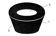
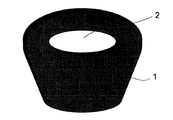
- FIG. 6 is an external view of a vent plug according to Embodiment 4 of the present invention. Basically, it is the same as the vent plug according to the first to third embodiments, but in the fourth embodiment, the opening 3 is formed over the entire circumference of the side surface of the tubular member 1. Thereby, the formation state of the ventilation film 2 can be confirmed from all directions.
- the inner diameter of the lower cylindrical member and the upper cylinder Preferably, the inner diameter of the cylindrical member is substantially the same, and the outer diameter of the lower cylindrical member and the outer diameter of the upper cylindrical member are substantially the same. The reason is that when the inner diameter or the outer diameter is greatly different, stress may be generated due to the difference in thermal contraction between the upper cylindrical member and the lower cylindrical member, and the vent plug may be deformed.
- the inner diameter and the outer diameter are specified at a portion in contact with the gas permeable membrane 2.
- the tubular member 1 is provided below the gas permeable membrane 2. It is preferable to use a vent plug (for example, FIGS. 1 to 3) in which the existing portion and the upper portion are connected by a wider area.
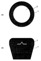
- FIG. 7A is a plan view (top view) of a vent plug according to Embodiment 5 of the present invention
- FIG. 7B is a side view thereof.
- the cylindrical member 1 has a concavo-convex shape on the surface sandwiching the peripheral edge portion of the gas permeable membrane 2.
- the gas permeable membrane 2 may have anisotropy depending on the direction of the membrane, the directionality of the gas permeable membrane 2 can be displayed by providing an uneven shape.
- the gas permeable membrane 2 and the cylindrical member 1 are more firmly fixed by the uneven shape.
- FIG. 8A is a plan view (top view) of a vent plug according to Embodiment 6 of the present invention
- FIG. 8B is a side view thereof.
- the surface sandwiching the peripheral edge of the gas permeable membrane 2 has an uneven shape.
- the directionality of the gas permeable membrane 2 can be displayed by providing an uneven shape.
- the directionality of the ventilation film 2 can also be confirmed even if it sees from the upper surface side of a ventilation plug.
- the vent surface is provided with an uneven shape in this way, the vent area of the vent film 2 is increased, so that the pressure loss of the vent plug is reduced. Further, as in the case of the fifth embodiment, the gas permeable membrane 2 and the tubular member 1 are more firmly fixed.
- the cylindrical member 1 is preferably made of an elastic resin in consideration of the use of inserting a vent plug into a casing or the like of an electric device as described above.
- the resin include elastic resins mainly composed of olefins such as santoprene and minastomer, rubber-based elastic resins such as ethylene propylene rubber (EPDM), acrylic rubber, silicon rubber, and fluorine rubber, or polypropylene (PP ) Is desirable.
- EPDM ethylene propylene rubber
- PP polypropylene
- the cylindrical member 1 has a structure in which the gas permeable membrane 2 is sandwiched from above and below as described above, but different types of materials may be used for the upper side and the lower side of the gas permeable membrane 2.
- the cylindrical member 1 has a hardness (JIS K 6253) of 100 degrees or less, more preferably 80 degrees or less.
- the angle is 10 degrees or more, more preferably 40 degrees or more.
- a durometer manufactured by Shimadzu Corporation: DUROMETER A is used for measuring the rubber hardness.
- the height of the end (projection) of the cylindrical member 1 as viewed from the plane including the gas permeable membrane 2 is preferably 5 to 200%, more preferably 10 to 100, with respect to the diameter of the through hole 1a of the cylindrical member 1. %, More preferably 15 to 50%.
- Breathable membrane As a constituent material of the breathable membrane 2, polyethylene, polypropylene, polystyrene, polyimide, etc. can be used, preferably a fluororesin excellent in waterproofness, more preferably porous polytetrafluoroethylene. It is recommended to use (porous PTFE) film. As the microscopic shape of the gas permeable membrane 2, a net shape, a mesh shape, or a porous shape can be used. The porous PTFE film is excellent in drip-proofing properties and is suitable for applications in which the inside and outside of an electric device have air permeability while preventing intrusion of water droplets, oil droplets and dust.
- a porous PTFE film is obtained by removing a molding aid from a molded body of a paste obtained by mixing PTFE fine powder with a molding aid, stretching at a high temperature and a high speed, and further firing if necessary. It is obtained.
- the nodes folded crystals
- the fibrils straight-lined drawn by unfolding the folded crystals by stretching to connect the nodes
- Molecular bundle is oriented in the stretching direction.
- it has a fibrous structure in which spaces defined between fibrils or between fibrils and nodes become holes.
- biaxial stretching the fibrils spread radially, the nodes connecting the fibrils are scattered in islands, and a cobweb-like fibrous structure in which many spaces defined by the fibrils and the nodes exist. ing.
- the permeable membrane 2 may be a uniaxially stretched porous PTFE film or a biaxially stretched porous PTFE film.
- the gas permeable membrane 2 is preferably strong enough to be used alone (in a single layer), but has elasticity such as a nonwoven fabric, a net such as a woven fabric or a knitted fabric, and preferably has a breathability capable of withstanding a high temperature of 120 ° C. You may use it, laminating
- the gas permeable membrane 2 As the physical characteristics of the gas permeable membrane 2, it is desirable to have a water pressure resistance of 1 kPa or more, more preferably 10 kPa or more, and an air permeability (JIS P 8117) of 1000 seconds or less, more preferably 100 seconds or less.
- the gas permeable membrane 2 is preferably provided with liquid repellency on the inner surface of the pores.
- liquid repellency By imparting liquid repellency to the gas permeable membrane 2, it is possible to prevent various contaminants such as body fat, machine oil, and water droplets from penetrating or being retained in the pores of the gas permeable membrane. These contaminants reduce the trapping characteristics and ventilation characteristics of the gas permeable membrane and cause the function of the gas permeable membrane to be impaired.
- liquid repellent includes “water repellent”, “oil repellent”, “water repellent”, and the like.
- water- and oil-repellent polymer will be described as an example.
- water / oil repellent polymer a polymer having a fluorine-containing side chain can be used. Details of the water- and oil-repellent polymer and the method of combining it with a porous PTFE film are disclosed in WO94 / 22928.
- the double-sided pressure-sensitive adhesive tape includes a nonwoven fabric-based double-sided pressure-sensitive adhesive tape, a PET-based double-sided pressure-sensitive adhesive tape, a polyimide-based double-sided pressure-sensitive adhesive tape, a nylon-based double-sided pressure-sensitive adhesive tape, and foam.
- body for example, urethane foam, silicone foam, acrylic foam, polyethylene foam
- base material double-sided pressure-sensitive adhesive tape and base material-less double-sided pressure-sensitive adhesive tape can be used.
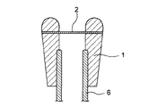
- vent plug of the present invention is attached directly or indirectly to a case (housing) that houses an electronic component inside, for example, the shape of the cylindrical member 1 can be variously changed depending on the shape of the attachment portion. .
- a vent plug may be attached to a bottomed hole provided in a part of the case (housing) 7.
- a vent plug excellent in shielding properties and attachment strength can be produced.
- At least two annular convex portions 5 may be formed on the side surface of the cylindrical member 1 with the opening 3 interposed therebetween. Good. Although it is usually considered to provide one convex portion 5 in order to improve the fitting and shielding properties (sealing performance) between the vent plug and the inner wall surface of the hole, in order to further improve the fitting property and shielding performance of the vent plug. It is preferable to provide two convex portions 5. For example, if foreign matter or dust is sandwiched between the vent plug and the hole, or if the hole has a flaw, the fit of the vent plug is poor and gas leakage may occur. In that respect, the possibility of gas leakage decreases if two convex portions 5 are provided.
- a sealed space is formed by the cylindrical member 1, the convex portion 5, and the hole.
- injection molding Injection molding
- a melted thermoplastic resin is press-fitted into a mold processed into a predetermined concave shape, and then the thermoplastic resin is cooled to obtain a molded product of a vent plug.
- the process procedure is shown by the process cross-sectional views of FIGS.
- the first mold 11 and the second mold 12 are brought into close contact with each other to form a cavity in the shape of the cylindrical member 1 inside the mold.
- the gas permeable membrane 2 is sandwiched between the first mold 11 and the second mold 12 in advance.
- thermoplastic resin melted from the injection port 13 is injected into the first mold 11.
- the resin is impregnated into the void portion of the gas permeable membrane 2 (for example, PTFE porous body) by the injection pressure of the resin, and further, the resin is cooled and cured, so that the resin (that is, a molded cylinder)
- the member 1) and the gas permeable membrane 2 are firmly fixed by the anchor effect.
- first metal mold 11 and the second metal mold 12 are removed from the mold, and the excess air-permeable membrane 2 is cut to obtain a vent plug composed of the tubular member 1 and the air-permeable membrane 2. Can do.
Landscapes
- Engineering & Computer Science (AREA)
- Mechanical Engineering (AREA)
- Microelectronics & Electronic Packaging (AREA)
- Examining Or Testing Airtightness (AREA)
- Manufacture Of Porous Articles, And Recovery And Treatment Of Waste Products (AREA)
- Separation Using Semi-Permeable Membranes (AREA)
Abstract
L'invention porte sur un bouchon perméable à l'air grâce auquel on peut facilement identifier, par observation de l'aspect, si un film perméable à l'air (2) est inséré de manière appropriée à l'intérieur d'un élément tubulaire (1). Un bouchon perméable à l'air est fabriqué, lequel est équipé de l'élément tubulaire (1) ayant un trou traversant (1a) et le film perméable à l'air (2) traversant le trou traversant (1a), et la partie périphérique du film perméable à l'air (2) étant maintenue de manière sûre par l'élément tubulaire (1), et la surface latérale de l'élément tubulaire (1) comportant une ouverture (3) qui permet de confirmer visuellement l'extrémité périphérique du film perméable à l'air (2).
Applications Claiming Priority (2)
| Application Number | Priority Date | Filing Date | Title |
|---|---|---|---|
| JP2009-140889 | 2009-06-12 | ||
| JP2009140889A JP5563245B2 (ja) | 2009-06-12 | 2009-06-12 | 通気栓及び通気栓の検査方法 |
Publications (1)
| Publication Number | Publication Date |
|---|---|
| WO2010143624A1 true WO2010143624A1 (fr) | 2010-12-16 |
Family
ID=43308879
Family Applications (1)
| Application Number | Title | Priority Date | Filing Date |
|---|---|---|---|
| PCT/JP2010/059687 Ceased WO2010143624A1 (fr) | 2009-06-12 | 2010-06-08 | Bouchon perméable à l'air et procédé d'inspection de bouchon perméable à l'air |
Country Status (2)
| Country | Link |
|---|---|
| JP (1) | JP5563245B2 (fr) |
| WO (1) | WO2010143624A1 (fr) |
Cited By (5)
| Publication number | Priority date | Publication date | Assignee | Title |
|---|---|---|---|---|
| CN102407732A (zh) * | 2011-10-26 | 2012-04-11 | 东风汽车股份有限公司 | 吊管式汽车后桥通气塞 |
| WO2013080494A1 (fr) * | 2011-11-28 | 2013-06-06 | 日東電工株式会社 | Élément de ventilation |
| WO2013183211A1 (fr) * | 2012-06-08 | 2013-12-12 | 日東電工株式会社 | Elément perméable étanche à l'eau et structure perméable |
| JPWO2016006615A1 (ja) * | 2014-07-07 | 2017-06-01 | 国立大学法人 東京大学 | バルブ、流体デバイス、流体制御方法及びバルブの製造方法 |
| CN111122071A (zh) * | 2019-12-31 | 2020-05-08 | 广东罗曼智能科技股份有限公司 | 一种电动牙刷的气密性检测装置 |
Families Citing this family (2)
| Publication number | Priority date | Publication date | Assignee | Title |
|---|---|---|---|---|
| JP6560001B2 (ja) * | 2015-04-06 | 2019-08-14 | 積水樹脂株式会社 | フィルム巻き上げパイプの製造方法 |
| JP6726984B2 (ja) * | 2016-02-29 | 2020-07-22 | フクダ電子株式会社 | パルスオキシメータの防水検査構造 |
Citations (6)
| Publication number | Priority date | Publication date | Assignee | Title |
|---|---|---|---|---|
| JPH0276277U (fr) * | 1988-07-15 | 1990-06-12 | ||
| EP0816043A1 (fr) * | 1996-07-03 | 1998-01-07 | W.L. GORE & ASSOCIATES GmbH | Procédé de fabrication d'un élément de fermeture sous forme d'une pièce en matière plastique moulée par injection ainsi que l'élément de fermeture fabriqué par ce procédé |
| WO2001096197A2 (fr) * | 2000-06-16 | 2001-12-20 | Utz Kador | Dispositif de fermeture |
| WO2006123717A1 (fr) * | 2005-05-18 | 2006-11-23 | Nitto Denko Corporation | Element permeable au gaz et boitier permeable au gaz l’utilisant |
| JP2006315725A (ja) * | 2005-05-13 | 2006-11-24 | Tokai Kogyo Co Ltd | 通気部品及び通気部品の製造方法並びに防水性通気膜 |
| JP2008237949A (ja) * | 2007-03-23 | 2008-10-09 | Nitto Denko Corp | 防水通気フィルタ、防水通気部材および筐体 |
Family Cites Families (6)
| Publication number | Priority date | Publication date | Assignee | Title |
|---|---|---|---|---|
| JPS63153410U (fr) * | 1987-03-30 | 1988-10-07 | ||
| JP2002143624A (ja) * | 2000-11-14 | 2002-05-21 | Saint-Gobain Norton Kk | 通気フィルターおよびフィルター付き容器 |
| JP2003090721A (ja) * | 2001-09-19 | 2003-03-28 | Bridgestone Corp | ゴム部材の検出方法、及びゴム部材の貼付方法 |
| JP2006085100A (ja) * | 2004-09-17 | 2006-03-30 | Ricoh Co Ltd | 構成部品判別装置、生産システム、及び画像形成装置 |
| JP4879475B2 (ja) * | 2004-11-19 | 2012-02-22 | 日東電工株式会社 | 通気フィルタ部材およびそれを利用した通気筐体 |
| JP2009007439A (ja) * | 2007-06-27 | 2009-01-15 | Nitto Denko Corp | 撥液性を有する通気膜の製造方法と撥液性を有する通気膜ならびに通気部材 |
-
2009
- 2009-06-12 JP JP2009140889A patent/JP5563245B2/ja active Active
-
2010
- 2010-06-08 WO PCT/JP2010/059687 patent/WO2010143624A1/fr not_active Ceased
Patent Citations (6)
| Publication number | Priority date | Publication date | Assignee | Title |
|---|---|---|---|---|
| JPH0276277U (fr) * | 1988-07-15 | 1990-06-12 | ||
| EP0816043A1 (fr) * | 1996-07-03 | 1998-01-07 | W.L. GORE & ASSOCIATES GmbH | Procédé de fabrication d'un élément de fermeture sous forme d'une pièce en matière plastique moulée par injection ainsi que l'élément de fermeture fabriqué par ce procédé |
| WO2001096197A2 (fr) * | 2000-06-16 | 2001-12-20 | Utz Kador | Dispositif de fermeture |
| JP2006315725A (ja) * | 2005-05-13 | 2006-11-24 | Tokai Kogyo Co Ltd | 通気部品及び通気部品の製造方法並びに防水性通気膜 |
| WO2006123717A1 (fr) * | 2005-05-18 | 2006-11-23 | Nitto Denko Corporation | Element permeable au gaz et boitier permeable au gaz l’utilisant |
| JP2008237949A (ja) * | 2007-03-23 | 2008-10-09 | Nitto Denko Corp | 防水通気フィルタ、防水通気部材および筐体 |
Cited By (10)
| Publication number | Priority date | Publication date | Assignee | Title |
|---|---|---|---|---|
| CN102407732A (zh) * | 2011-10-26 | 2012-04-11 | 东风汽车股份有限公司 | 吊管式汽车后桥通气塞 |
| WO2013080494A1 (fr) * | 2011-11-28 | 2013-06-06 | 日東電工株式会社 | Élément de ventilation |
| JP2013114829A (ja) * | 2011-11-28 | 2013-06-10 | Nitto Denko Corp | 通気部材 |
| CN103958964A (zh) * | 2011-11-28 | 2014-07-30 | 日东电工株式会社 | 透气部件 |
| EP2787277A4 (fr) * | 2011-11-28 | 2015-12-23 | Nitto Denko Corp | Élément de ventilation |
| US9255719B2 (en) | 2011-11-28 | 2016-02-09 | Nitto Denko Corporation | Ventilation member |
| CN103958964B (zh) * | 2011-11-28 | 2017-03-29 | 日东电工株式会社 | 透气部件 |
| WO2013183211A1 (fr) * | 2012-06-08 | 2013-12-12 | 日東電工株式会社 | Elément perméable étanche à l'eau et structure perméable |
| JPWO2016006615A1 (ja) * | 2014-07-07 | 2017-06-01 | 国立大学法人 東京大学 | バルブ、流体デバイス、流体制御方法及びバルブの製造方法 |
| CN111122071A (zh) * | 2019-12-31 | 2020-05-08 | 广东罗曼智能科技股份有限公司 | 一种电动牙刷的气密性检测装置 |
Also Published As
| Publication number | Publication date |
|---|---|
| JP5563245B2 (ja) | 2014-07-30 |
| JP2010286378A (ja) | 2010-12-24 |
Similar Documents
| Publication | Publication Date | Title |
|---|---|---|
| JP5563245B2 (ja) | 通気栓及び通気栓の検査方法 | |
| JP5622369B2 (ja) | 通気栓 | |
| JP6130183B2 (ja) | 通気部材 | |
| CN104080305B (zh) | 防水通气结构、防水通气构件及防水通气膜 | |
| KR100638981B1 (ko) | 통기 부재와, 이 통기 부재를 포함하는 통기 하우징 | |
| KR100685555B1 (ko) | 통기 부재와, 이 통기 부재를 포함하는 통기 하우징 | |
| US8246726B2 (en) | Ventilation member | |
| CN104075301B (zh) | 透气构件 | |
| JP6130182B2 (ja) | 通気部材 | |
| JP6431451B2 (ja) | 通気部材付き樹脂部材及びその製造方法、筐体並びにセンサ | |
| US20150114090A1 (en) | Mobile device and waterproof test method | |
| CN104540887B (zh) | 聚四氟乙烯黑色多孔膜、其制造方法、使用该多孔膜的透气膜和透气构件 | |
| US20140047981A1 (en) | Ventilation unit | |
| KR20100103557A (ko) | 폴리테트라플루오로에틸렌 다공질막과 그 제조 방법, 및 방수 통기 필터 | |
| TWI674188B (zh) | 氣體透過構件及其製造方法 | |
| TW201924364A (zh) | 防水透音構件及具備其之電子機器 | |
| WO2013031085A1 (fr) | Élément d'assemblage ayant une fonction de ventilation et structure d'assemblage l'utilisant | |
| JP6538863B2 (ja) | ベント装置 | |
| JP7731527B1 (ja) | 通気膜、通気部材及び発光デバイス | |
| CN206247260U (zh) | 灯具及其密封光学罩 | |
| CN209042007U (zh) | 照明装置 | |
| CN121697311A (zh) | 具有椭圆形及岛形微观特征的ePTFE微孔膜贴片组件及其在汽车电气设备中的应用 |
Legal Events
| Date | Code | Title | Description |
|---|---|---|---|
| 121 | Ep: the epo has been informed by wipo that ep was designated in this application |
Ref document number: 10786155 Country of ref document: EP Kind code of ref document: A1 |
|
| NENP | Non-entry into the national phase |
Ref country code: DE |
|
| 122 | Ep: pct application non-entry in european phase |
Ref document number: 10786155 Country of ref document: EP Kind code of ref document: A1 |