WO2010143624A1 - 通気栓及び通気栓の検査方法 - Google Patents
通気栓及び通気栓の検査方法 Download PDFInfo
- Publication number
- WO2010143624A1 WO2010143624A1 PCT/JP2010/059687 JP2010059687W WO2010143624A1 WO 2010143624 A1 WO2010143624 A1 WO 2010143624A1 JP 2010059687 W JP2010059687 W JP 2010059687W WO 2010143624 A1 WO2010143624 A1 WO 2010143624A1
- Authority
- WO
- WIPO (PCT)
- Prior art keywords
- vent plug
- vent
- permeable membrane
- gas permeable
- cylindrical member
- Prior art date
- Legal status (The legal status is an assumption and is not a legal conclusion. Google has not performed a legal analysis and makes no representation as to the accuracy of the status listed.)
- Ceased
Links
Images


Classifications
-
- B—PERFORMING OPERATIONS; TRANSPORTING
- B65—CONVEYING; PACKING; STORING; HANDLING THIN OR FILAMENTARY MATERIAL
- B65D—CONTAINERS FOR STORAGE OR TRANSPORT OF ARTICLES OR MATERIALS, e.g. BAGS, BARRELS, BOTTLES, BOXES, CANS, CARTONS, CRATES, DRUMS, JARS, TANKS, HOPPERS, FORWARDING CONTAINERS; ACCESSORIES, CLOSURES, OR FITTINGS THEREFOR; PACKAGING ELEMENTS; PACKAGES
- B65D51/00—Closures not otherwise provided for
- B65D51/16—Closures not otherwise provided for with means for venting air or gas
- B65D51/1605—Closures not otherwise provided for with means for venting air or gas whereby the interior of the container is maintained in permanent gaseous communication with the exterior
- B65D51/1616—Closures not otherwise provided for with means for venting air or gas whereby the interior of the container is maintained in permanent gaseous communication with the exterior by means of a filter
-
- H—ELECTRICITY
- H05—ELECTRIC TECHNIQUES NOT OTHERWISE PROVIDED FOR
- H05K—PRINTED CIRCUITS; CASINGS OR CONSTRUCTIONAL DETAILS OF ELECTRIC APPARATUS; MANUFACTURE OF ASSEMBLAGES OF ELECTRICAL COMPONENTS
- H05K5/00—Casings, cabinets or drawers for electric apparatus
- H05K5/02—Details
- H05K5/0213—Venting apertures; Constructional details thereof
- H05K5/0216—Venting plugs comprising semi-permeable membranes
-
- F—MECHANICAL ENGINEERING; LIGHTING; HEATING; WEAPONS; BLASTING
- F21—LIGHTING
- F21S—NON-PORTABLE LIGHTING DEVICES; SYSTEMS THEREOF; VEHICLE LIGHTING DEVICES SPECIALLY ADAPTED FOR VEHICLE EXTERIORS
- F21S45/00—Arrangements within vehicle lighting devices specially adapted for vehicle exteriors, for purposes other than emission or distribution of light
- F21S45/30—Ventilation or drainage of lighting devices
Definitions
- the present invention relates to a vent plug provided with a vent film having a function of blocking liquid such as water droplets and oil droplets while allowing gas to pass through, and a method for inspecting the vent plug.
- Patent Documents 1 to 3 disclose a vent plug that allows gas to enter and exit while preventing intrusion of liquid such as water droplets by forming a drip-proof vent film at one end of a cylindrical member. Are listed. Further, it is described that the vent plug is suitably used for electric devices such as a motor case.
- JP 2001-143524 A (FIG. 1) JP 2003-63549 A (FIGS. 1 and 2) JP 2008-148388 A (FIGS. 4 and 5)
- the vent membrane When the conventional vent plug is used, when the vent plug is handled, for example, when the vent plug is mounted on the motor case, the operator's fingers and attachment devices (hereinafter referred to as “finger fingers”) are used as the vent membrane. There was a case where it was damaged by contact. Under such circumstances, the applicant has so far studied a structure for making it difficult for fingers and the like to come into direct contact with the gas permeable membrane.
- the ventilation film 2 is not formed on the end surface of the cylindrical member 1, but is vented into the cylindrical member 1 at a position slightly inward from the end of the cylindrical member 1.
- a structure for sandwiching the film 2 has been studied. With such a configuration, the end portion of the cylindrical member 1 has a structure that protrudes upward from the plane including the gas permeable membrane 2, so that the end surface of the cylindrical member 1 functions as a protective bank against fingers and the like. The probability that a finger etc. will contact 2 directly can be reduced.
- an object of the present invention is to provide a vent plug that can easily identify whether or not the gas permeable membrane 2 is properly sandwiched inside the cylindrical member 1 by observing the appearance.
- vent plug of the present invention capable of achieving the above-mentioned object is A vent plug comprising a tubular member having a through hole and a gas permeable membrane crossing the through hole, wherein a peripheral portion of the gas permeable membrane is sandwiched between the cylindrical members, and on the side surface of the cylindrical member The opening part which can visually recognize the peripheral edge part of the said air permeable membrane is formed.
- the hues of the tubular member and the gas permeable membrane are separated from each other by 15 ° or more when the entire circumference of the hue ring, which is a measure of hue, is 360 °.
- the tubular member and the gas permeable membrane differ in brightness by 1 degree or more.
- the cylindrical member and the gas permeable membrane differ in saturation by 2 degrees or more.
- the opening may be formed over the entire circumference of the side surface of the cylindrical member.
- the vent film and / or the cylindrical member contain one or more of a phosphorescent agent, a fluorescent agent, and a light reflecting material.
- the cylindrical member has a concavo-convex shape on a surface sandwiching a peripheral portion of the vent film.
- vent plug it is preferable that at least two annular convex portions are formed on the side surface of the cylindrical member with the opening interposed therebetween.
- the non-opening portion between adjacent openings is 90 ° or less. Is desirable.
- a reinforcing film is formed on one side or both sides of the vent film.
- vent film has liquid repellency.
- peripheral edge portion of the gas permeable membrane visually recognized from the opening portion also has liquid repellency.
- the gas permeable membrane is composed of a porous polytetrafluoroethylene membrane.
- a desirable inspection method for the vent plug includes a step of photographing a side image of the vent plug and a step of determining whether or not the vent film is appropriately fixed from the side image.
- the peripheral portion of the gas permeable membrane is sandwiched by the cylindrical member, and a predetermined opening that allows the peripheral edge portion of the gas permeable membrane to be visually recognized is formed on the side surface of the cylindrical member. Since the inside of the cylindrical member can be visually recognized through the opening, it can be determined that the gas permeable membrane is appropriately held.
- Embodiment 1 of the present invention It is an external view of the vent plug concerning Embodiment 1 of the present invention. It is a side view of the vent plug. It is sectional drawing of the vent plug. It is an external view of the vent plug concerning Embodiment 2 of the present invention. It is an external view of the vent plug concerning Embodiment 3 of the present invention. It is an external view of the vent plug concerning Embodiment 4 of the present invention.
- A) is a top view of the vent plug according to Embodiment 5 of the present invention, and (b) is a side view of the vent plug.
- A) is a top view of the vent plug according to Embodiment 6 of the present invention, and (b) is a side view of the vent plug.
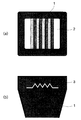
- FIG. 1 is an external view of a vent plug according to Embodiment 1 of the present invention
- FIG. 2 is a side view of the vent plug
- FIG. 3 is a cross-sectional view of the vent plug. 1 to 3
- a tubular plug 1 having a through hole 1a and a vent film 2 crossing the through hole 1a constitute a vent plug.
- the peripheral part of the gas permeable membrane 2 is sandwiched between the cylindrical members 1, and an opening 3 is formed on the side surface of the cylindrical member 1 so that the peripheral edge of the gas permeable film 2 can be visually recognized.
- the presence state of the peripheral edge of the gas permeable membrane 2 can be grasped through the opening 3. For example, if the presence of the peripheral edge of the gas permeable membrane 2 is confirmed in the opening 3, it is determined that the gas permeable membrane 2 is appropriately fixed at a predetermined position. On the other hand, if the presence of the gas permeable membrane 2 is not confirmed in the opening 3, it can be determined that the gas permeable membrane 2 is not arranged at a predetermined position as in the example shown in FIG. 14 or FIG. . The vent plug thus determined is discarded as a defective product.
- the inspection of the gas permeable membrane 2 can be performed visually, but can also be automated. You may employ
- inspection method of a vent plug including the process of image
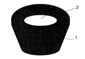
- FIG. 4 is an external view of a vent plug according to Embodiment 2 of the present invention.
- the color of the tubular member 1 and the vent film 2 is different from the vent plug according to the first embodiment.
- the tubular member 1 has a color close to black
- the vent film 2 has a color close to white. Therefore, the contrast between the tubular member 1 and the vent film 2 is high. It ’s good.
- the tubular member 1 has a color close to white
- the vent film 2 has a color close to black, and similarly has good contrast.
- the gist of the present invention is to confirm the presence of the gas permeable membrane 2 through the opening 3 of the tubular member 1 as described above. Therefore, it is more preferable that the difference in appearance between the tubular member 1 and the gas permeable membrane 2 is large. Various factors such as color differences due to material differences, light reflectance differences, surface roughness differences, texture differences, etc. can be considered as factors that cause differences in appearance. Is preferable for identification.
- colors have three elements: hue, brightness, and saturation. In the present embodiment, it is defined for each of the three elements whether a color difference between the tubular member 1 and the gas permeable membrane 2 is preferable for identifying the gas permeable membrane 2.
- the hue H can be specified using a hue circle.
- the hue circle is an arrangement in which the total hue is divided and arranged in an annular shape so that the difference in hue perception is approximately equal.
- complementary colors are provided at opposite positions.
- the color wheel is theoretically continuous and continuous.
- the hue circle is expressed in 30 divisions.
- what is expressed in 24 divisions (Nippon Color Research Co., Ltd. hue ring) is also known.
- the difference in hue H is indicated by the angle between the two colors when the entire circumference of the hue circle is 360 °.
- the hue difference between the tubular member 1 and the gas permeable membrane 2 is preferably 15 ° or more.
- the angle of 15 ° is an angle representing the interval between adjacent hues in the hue circle obtained by dividing the entire circumference of 360 ° into 24 parts. More preferably, it is 30 ° or more.
- Lightness (V) Among the attributes of color perception, the lightness V is divided so that the ideal black is 0 degrees and the ideal white is 10 degrees on the basis of the achromatic color, and the difference in lightness perception is approximately equal.
- the intermediate brightness V belonging to this range is expressed by 1 to 9 degrees (see 3.2 “Lightness Display Method” of JIS Z1821).
- the lightness difference between the tubular member 1 and the gas permeable membrane 2 is preferably 1 degree or more. More preferably, it is 2 degrees or more.
- JIS Z1821 6 (2) “Method determined from direct comparison with standard color standard” can be used.
- saturation C indicates the degree of chromatic color
- achromatic color is set to 0, and is sequentially expressed as 1, 2, 3, 4 in accordance with a constant increase in the degree of saturation.
- the saturation difference between the tubular member 1 and the gas permeable membrane 2 is preferably 2 degrees or more. More preferably, it is 3 degrees or more.
- JIS Z1821 6 (2) “Method determined from direct comparison with standard color standard” can be used.
- a method of adding a light emitting material is used in order to improve the distinguishability between the tubular member 1 and the gas permeable membrane 2. Also good.
- a luminescent material one or more of a phosphorescent agent, a fluorescent agent, and a light reflecting material can be added to one or both of the tubular member 1 and the gas permeable membrane 2.
- the luminous agent for example, zinc sulfide activated copper or aluminum oxide or strontium oxide crystallized is used.
- fluorescent agents zinc sulfide phosphors, halophosphate phosphors and the like are typically known.
- the light reflecting material for example, metal particles such as platinum, gold, silver, and aluminum, glass particles such as borosilicate and soda lime, mineral particles such as mica particles, and the like can be used.
- FIG. 5 is an external view of a vent plug according to Embodiment 3 of the present invention. Basically, it is the same as the vent plug according to the first embodiment, but in the third embodiment, four openings 3 are provided (of which the opening shown in FIG. Two openings 3a and 3b). Furthermore, in Embodiment 3, when the whole side surface circumference of the cylindrical member 1 is set to 360 °, all the non-opening portions between adjacent opening portions are designed to be 90 ° or less. That is, as shown in FIG. 5, the non-opening portion between the opening 3a and the opening 3b is designed to have an expansion angle ⁇ (90 ° or less) when viewed from the central axis of the tubular member 1. Yes.
- ⁇ 90 ° or less
- the case where the number of the opening portions 3 is four has been described. However, it can be appropriately adjusted depending on the extension range of the opening portions 3 and the size of the vent plug, for example, Two or more are preferably present.
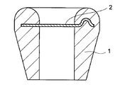
- FIG. 6 is an external view of a vent plug according to Embodiment 4 of the present invention. Basically, it is the same as the vent plug according to the first to third embodiments, but in the fourth embodiment, the opening 3 is formed over the entire circumference of the side surface of the tubular member 1. Thereby, the formation state of the ventilation film 2 can be confirmed from all directions.
- the inner diameter of the lower cylindrical member and the upper cylinder Preferably, the inner diameter of the cylindrical member is substantially the same, and the outer diameter of the lower cylindrical member and the outer diameter of the upper cylindrical member are substantially the same. The reason is that when the inner diameter or the outer diameter is greatly different, stress may be generated due to the difference in thermal contraction between the upper cylindrical member and the lower cylindrical member, and the vent plug may be deformed.
- the inner diameter and the outer diameter are specified at a portion in contact with the gas permeable membrane 2.
- the tubular member 1 is provided below the gas permeable membrane 2. It is preferable to use a vent plug (for example, FIGS. 1 to 3) in which the existing portion and the upper portion are connected by a wider area.
- FIG. 7A is a plan view (top view) of a vent plug according to Embodiment 5 of the present invention
- FIG. 7B is a side view thereof.
- the cylindrical member 1 has a concavo-convex shape on the surface sandwiching the peripheral edge portion of the gas permeable membrane 2.
- the gas permeable membrane 2 may have anisotropy depending on the direction of the membrane, the directionality of the gas permeable membrane 2 can be displayed by providing an uneven shape.
- the gas permeable membrane 2 and the cylindrical member 1 are more firmly fixed by the uneven shape.
- FIG. 8A is a plan view (top view) of a vent plug according to Embodiment 6 of the present invention
- FIG. 8B is a side view thereof.
- the surface sandwiching the peripheral edge of the gas permeable membrane 2 has an uneven shape.
- the directionality of the gas permeable membrane 2 can be displayed by providing an uneven shape.
- the directionality of the ventilation film 2 can also be confirmed even if it sees from the upper surface side of a ventilation plug.
- the vent surface is provided with an uneven shape in this way, the vent area of the vent film 2 is increased, so that the pressure loss of the vent plug is reduced. Further, as in the case of the fifth embodiment, the gas permeable membrane 2 and the tubular member 1 are more firmly fixed.
- the cylindrical member 1 is preferably made of an elastic resin in consideration of the use of inserting a vent plug into a casing or the like of an electric device as described above.
- the resin include elastic resins mainly composed of olefins such as santoprene and minastomer, rubber-based elastic resins such as ethylene propylene rubber (EPDM), acrylic rubber, silicon rubber, and fluorine rubber, or polypropylene (PP ) Is desirable.
- EPDM ethylene propylene rubber
- PP polypropylene
- the cylindrical member 1 has a structure in which the gas permeable membrane 2 is sandwiched from above and below as described above, but different types of materials may be used for the upper side and the lower side of the gas permeable membrane 2.
- the cylindrical member 1 has a hardness (JIS K 6253) of 100 degrees or less, more preferably 80 degrees or less.
- the angle is 10 degrees or more, more preferably 40 degrees or more.
- a durometer manufactured by Shimadzu Corporation: DUROMETER A is used for measuring the rubber hardness.
- the height of the end (projection) of the cylindrical member 1 as viewed from the plane including the gas permeable membrane 2 is preferably 5 to 200%, more preferably 10 to 100, with respect to the diameter of the through hole 1a of the cylindrical member 1. %, More preferably 15 to 50%.
- Breathable membrane As a constituent material of the breathable membrane 2, polyethylene, polypropylene, polystyrene, polyimide, etc. can be used, preferably a fluororesin excellent in waterproofness, more preferably porous polytetrafluoroethylene. It is recommended to use (porous PTFE) film. As the microscopic shape of the gas permeable membrane 2, a net shape, a mesh shape, or a porous shape can be used. The porous PTFE film is excellent in drip-proofing properties and is suitable for applications in which the inside and outside of an electric device have air permeability while preventing intrusion of water droplets, oil droplets and dust.
- a porous PTFE film is obtained by removing a molding aid from a molded body of a paste obtained by mixing PTFE fine powder with a molding aid, stretching at a high temperature and a high speed, and further firing if necessary. It is obtained.
- the nodes folded crystals
- the fibrils straight-lined drawn by unfolding the folded crystals by stretching to connect the nodes
- Molecular bundle is oriented in the stretching direction.
- it has a fibrous structure in which spaces defined between fibrils or between fibrils and nodes become holes.
- biaxial stretching the fibrils spread radially, the nodes connecting the fibrils are scattered in islands, and a cobweb-like fibrous structure in which many spaces defined by the fibrils and the nodes exist. ing.
- the permeable membrane 2 may be a uniaxially stretched porous PTFE film or a biaxially stretched porous PTFE film.
- the gas permeable membrane 2 is preferably strong enough to be used alone (in a single layer), but has elasticity such as a nonwoven fabric, a net such as a woven fabric or a knitted fabric, and preferably has a breathability capable of withstanding a high temperature of 120 ° C. You may use it, laminating
- the gas permeable membrane 2 As the physical characteristics of the gas permeable membrane 2, it is desirable to have a water pressure resistance of 1 kPa or more, more preferably 10 kPa or more, and an air permeability (JIS P 8117) of 1000 seconds or less, more preferably 100 seconds or less.
- the gas permeable membrane 2 is preferably provided with liquid repellency on the inner surface of the pores.
- liquid repellency By imparting liquid repellency to the gas permeable membrane 2, it is possible to prevent various contaminants such as body fat, machine oil, and water droplets from penetrating or being retained in the pores of the gas permeable membrane. These contaminants reduce the trapping characteristics and ventilation characteristics of the gas permeable membrane and cause the function of the gas permeable membrane to be impaired.
- liquid repellent includes “water repellent”, “oil repellent”, “water repellent”, and the like.
- water- and oil-repellent polymer will be described as an example.
- water / oil repellent polymer a polymer having a fluorine-containing side chain can be used. Details of the water- and oil-repellent polymer and the method of combining it with a porous PTFE film are disclosed in WO94 / 22928.
- the double-sided pressure-sensitive adhesive tape includes a nonwoven fabric-based double-sided pressure-sensitive adhesive tape, a PET-based double-sided pressure-sensitive adhesive tape, a polyimide-based double-sided pressure-sensitive adhesive tape, a nylon-based double-sided pressure-sensitive adhesive tape, and foam.
- body for example, urethane foam, silicone foam, acrylic foam, polyethylene foam
- base material double-sided pressure-sensitive adhesive tape and base material-less double-sided pressure-sensitive adhesive tape can be used.
- vent plug of the present invention is attached directly or indirectly to a case (housing) that houses an electronic component inside, for example, the shape of the cylindrical member 1 can be variously changed depending on the shape of the attachment portion. .
- a vent plug may be attached to a bottomed hole provided in a part of the case (housing) 7.
- a vent plug excellent in shielding properties and attachment strength can be produced.
- At least two annular convex portions 5 may be formed on the side surface of the cylindrical member 1 with the opening 3 interposed therebetween. Good. Although it is usually considered to provide one convex portion 5 in order to improve the fitting and shielding properties (sealing performance) between the vent plug and the inner wall surface of the hole, in order to further improve the fitting property and shielding performance of the vent plug. It is preferable to provide two convex portions 5. For example, if foreign matter or dust is sandwiched between the vent plug and the hole, or if the hole has a flaw, the fit of the vent plug is poor and gas leakage may occur. In that respect, the possibility of gas leakage decreases if two convex portions 5 are provided.
- a sealed space is formed by the cylindrical member 1, the convex portion 5, and the hole.
- injection molding Injection molding
- a melted thermoplastic resin is press-fitted into a mold processed into a predetermined concave shape, and then the thermoplastic resin is cooled to obtain a molded product of a vent plug.
- the process procedure is shown by the process cross-sectional views of FIGS.
- the first mold 11 and the second mold 12 are brought into close contact with each other to form a cavity in the shape of the cylindrical member 1 inside the mold.
- the gas permeable membrane 2 is sandwiched between the first mold 11 and the second mold 12 in advance.
- thermoplastic resin melted from the injection port 13 is injected into the first mold 11.
- the resin is impregnated into the void portion of the gas permeable membrane 2 (for example, PTFE porous body) by the injection pressure of the resin, and further, the resin is cooled and cured, so that the resin (that is, a molded cylinder)
- the member 1) and the gas permeable membrane 2 are firmly fixed by the anchor effect.
- first metal mold 11 and the second metal mold 12 are removed from the mold, and the excess air-permeable membrane 2 is cut to obtain a vent plug composed of the tubular member 1 and the air-permeable membrane 2. Can do.
Landscapes
- Engineering & Computer Science (AREA)
- Mechanical Engineering (AREA)
- Microelectronics & Electronic Packaging (AREA)
- Examining Or Testing Airtightness (AREA)
- Manufacture Of Porous Articles, And Recovery And Treatment Of Waste Products (AREA)
- Separation Using Semi-Permeable Membranes (AREA)
Abstract
筒状部材1の内部に通気膜2が適切に挟み込まれているかどうかを外観の観察によって容易に識別できる通気栓を提供することを目的とする。貫通孔1aを有する筒状部材1と、貫通孔1aを横断する通気膜2とを備えた通気栓であって、通気膜2の周縁部は筒状部材1により挟持され、筒状部材1の側面には通気膜2の周縁端部を視認できる開口部3を設けた通気栓を作製する。
Description
本発明は、気体を通過させつつも水滴や油滴のような液体を遮断する機能を有する通気膜を備えた通気栓及び通気栓の検査方法に関するものである。
自動車のヘッドランプ、リアランプ、フォグランプ、パワーウィンドー、圧力センサー、圧力スイッチ、エンジンコントロールユニット等の電気装置は、水や油、界面活性剤等の液体に曝される環境下で使用されるものである。また一般家電製品の中でも、電気カミソリ、携帯電話、電動歯ブラシ等、水や油、界面活性剤等の液体に曝される環境下で使用されるものがある。これらの電気装置では、内部に電子部品を収納するケースの防滴性を高くする必要があるが、全くの密閉状態にしてしまうと、温度変化によってケース内部の気体が膨張・収縮する際に、ケース内外に圧力差が発生し、ケースに過大な負荷がかかってしまう。従って上記ケースは、液体の侵入を防止しつつも、気体は出入り可能な状態にしておく必要がある。
特許文献1~3には、筒状の部材の一端部に防滴性の通気膜を形成することにより、水滴等の液体の侵入を防止しつつも、気体の出入りを可能とする通気栓が記載されている。また、当該通気栓がモーターケース等の電気装置類に好適に使用されることが記載されている。
上記従来の通気栓を使用した場合、通気栓の取り扱い時、例えば、通気栓をモーターケースに装着する際に、作業者の手指や取り付け装置等(以下、「手指等」という)が通気膜に接触して破損することがあった。斯かる状況のもと、本出願人はこれまでに、手指等が通気膜に直接接触しにくくするための構造を検討してきた。
例えば、図13の断面図に示すように、通気膜2を筒状部材1の端面に形成するのではなく、筒状部材1の端部から少し内部寄りの位置において筒状部材1内に通気膜2を挟み込む構造を検討してきた。このような構成により、筒状部材1の端部は、通気膜2を含む平面よりも上方に突出する構造となるため、筒状部材1の端面が手指等に対する防護堤として機能し、通気膜2に手指等が直接接触してしまう確率を低減させることができる。
しかしながら、この方法では、筒状部材1の内部に通気膜2が適切な位置に挟み込まれているかどうかは、通気栓の外部からは検査することはできなかった。例えば、図14に示すように、通気膜2の端部が皺になっていても、図16の外観図に示すように外部からこれを容易に判別することはできない。また、図15に示すように、通気膜2の中心位置が筒状部材1の中心位置から大きくずれて形成された場合も同様であり、外部からこれを容易に判別することはできない。
図14や図15のように通気膜2の保持が不均一である場合、或いは不完全である場合、手指等、或いは風圧等の影響により、通気膜2が筒状部材1から外れてしまい、そこから水滴等が漏れ出てしまう可能性がある。そこで本発明は、筒状部材1の内部に通気膜2が適切に挟み込まれているかどうかを外観の観察によって容易に識別できる通気栓を提供することを目的とするものである。
上記目的を達成し得た本発明の通気栓は、
貫通孔を有する筒状部材と、前記貫通孔を横断する通気膜とを備えた通気栓であって、前記通気膜の周縁部は前記筒状部材により挟持され、前記筒状部材の側面には前記通気膜の周縁端部を視認できる開口部が形成されているものである。
貫通孔を有する筒状部材と、前記貫通孔を横断する通気膜とを備えた通気栓であって、前記通気膜の周縁部は前記筒状部材により挟持され、前記筒状部材の側面には前記通気膜の周縁端部を視認できる開口部が形成されているものである。
上記通気栓において、下記(1)~(3)の条件のうち、少なくとも1つを満足することが推奨される。
前記筒状部材と前記通気膜の色相は、色相の尺度である色相環の全周を360°とした場合に、互いに15°以上離れている。 (1)
前記筒状部材と前記通気膜は、明度が1度以上異なる。 (2)
前記筒状部材と前記通気膜は、彩度が2度以上異なる。 (3)
前記筒状部材と前記通気膜の色相は、色相の尺度である色相環の全周を360°とした場合に、互いに15°以上離れている。 (1)
前記筒状部材と前記通気膜は、明度が1度以上異なる。 (2)
前記筒状部材と前記通気膜は、彩度が2度以上異なる。 (3)
上記通気栓において、前記開口部が前記筒状部材側面の全周にわたり形成されていてもよい。
上記通気栓において、前記通気膜および/または前記筒状部材が、蓄光剤、蛍光剤、光反射材のいずれか1種以上を含有していることが望ましい。
上記通気栓において、前記筒状部材は、前記通気膜の周縁部を挟持する面に凹凸形状を有していることが望ましい。
上記通気栓において、前記筒状部材の側面には、前記開口部を挟んで少なくとも2つの環状の凸部が形成されていることが望ましい。
上記通気栓において、前記開口部を2つ以上有し、前記筒状部材の側面全周を360°としたとき、隣り合う開口部同士の間の非開口部分をいずれも90°以下とすることが望ましい。
上記通気栓において、前記通気膜の片面または両面に補強膜が形成されていることが望ましい。
上記通気栓において、前記通気膜が撥液性を有することが望ましい。また、前記開口部から視認される前記通気膜の周縁端部も撥液性を有することがいっそう望ましい。
上記通気栓において、前記通気膜を多孔質ポリテトラフルオロエチレン膜で構成することが望ましい。
上記通気栓の望ましい検査方法は、上記通気栓の側面像を撮影する工程と、該側面像から、前記通気膜が適切に固定されているか否かを判定する工程とを含む。
本発明の通気栓では、通気膜の周縁部が筒状部材により挟持され、筒状部材の側面には通気膜の周縁端部を視認できる所定の開口部が形成されている。この開口部を通して筒状部材の内部を視認することができるため、通気膜が適切に保持されていることを判別することができる。
1.通気栓の構造
以下、本発明の実施の形態における通気栓の構造について図面を参照しながら説明する。
以下、本発明の実施の形態における通気栓の構造について図面を参照しながら説明する。
(実施の形態1)
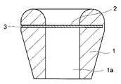
図1は本発明の実施の形態1に係る通気栓の外観図、図2は同通気栓の側面図、図3は同通気栓の断面図である。図1~3において、貫通孔1aを有する筒状部材1と、貫通孔1aを横断する通気膜2により通気栓が構成されている。通気膜2の周縁部は筒状部材1により挟持され、筒状部材1の側面には通気膜2の周縁端部を視認できる開口部3が形成されている。
図1は本発明の実施の形態1に係る通気栓の外観図、図2は同通気栓の側面図、図3は同通気栓の断面図である。図1~3において、貫通孔1aを有する筒状部材1と、貫通孔1aを横断する通気膜2により通気栓が構成されている。通気膜2の周縁部は筒状部材1により挟持され、筒状部材1の側面には通気膜2の周縁端部を視認できる開口部3が形成されている。
上記通気栓の作製後、この開口部3を通して通気膜2の周縁端部の存在状態を把握することができる。例えば、開口部3において、通気膜2の周縁端部の存在が確認されれば、通気膜2は所定の位置に適切に固定されていると判断される。一方、開口部3において通気膜2の存在が確認されなければ、通気膜2は、図14、或いは図15に示した例のように、所定の位置に配置されていないと判定することができる。そのように判定された通気栓は、不良品として廃棄される。
通気膜2の検査は目視によって行うこともできるが、自動化することもできる。製造された通気栓の側面像を撮影する工程と、側面像から、通気膜が適切に固定されているか否かを判定する工程とを含む通気栓の検査方法を採用してもよい。上記判定には、側面像において、開口部3内に所定割合以上(例えば80面積%以上)の通気膜2が存在している場合に良品と判断し、所定割合未満(例えば80面積%未満)しか通気膜2が確認されない場合に不良品と判断するステップを含ませることができる。
以上のように、筒状部材1の側面に開口部3を設けることにより、製造された通気栓の良/不良を容易かつ確実に判定することができる。
(実施の形態2)
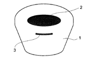
図4は、本発明の実施の形態2に係る通気栓の外観図である。実施の形態1に係る通気栓と同様のものであるが、実施の形態1に係る通気栓とは筒状部材1と通気膜2の色が異なる。実施の形態1に係る通気栓では、筒状部材1が黒に近い色を有しており、通気膜2が白に近い色を有していたため、筒状部材1と通気膜2のコントラストがよいものである。実施の形態2に係る通気栓では、筒状部材1が白に近い色を有し、通気膜2が黒に近い色を有しており、同様にコントラストがよい。本発明の要旨は、上記の通り、筒状部材1の開口部3を通して通気膜2の存在を確認することにある。したがって、筒状部材1と通気膜2との間で、外観上の差異が大きいことがより好ましい。外観上の差異が生じる要因としては、材質の違いによる色の違い、光反射率の違い、表面粗さの違い、質感の違い等、様々な違いが考えられるが、中でも色に違いがあることが識別する上で好ましい。
図4は、本発明の実施の形態2に係る通気栓の外観図である。実施の形態1に係る通気栓と同様のものであるが、実施の形態1に係る通気栓とは筒状部材1と通気膜2の色が異なる。実施の形態1に係る通気栓では、筒状部材1が黒に近い色を有しており、通気膜2が白に近い色を有していたため、筒状部材1と通気膜2のコントラストがよいものである。実施の形態2に係る通気栓では、筒状部材1が白に近い色を有し、通気膜2が黒に近い色を有しており、同様にコントラストがよい。本発明の要旨は、上記の通り、筒状部材1の開口部3を通して通気膜2の存在を確認することにある。したがって、筒状部材1と通気膜2との間で、外観上の差異が大きいことがより好ましい。外観上の差異が生じる要因としては、材質の違いによる色の違い、光反射率の違い、表面粗さの違い、質感の違い等、様々な違いが考えられるが、中でも色に違いがあることが識別する上で好ましい。
色には、よく知られているように、色相・明度・彩度の三要素が存在する。本実施の形態では、筒状部材1と通気膜2との間でどの程度の色の違いがあれば通気膜2の識別を行う上で好ましいのか、三要素のそれぞれについて規定するものである。
(1)色相(H)
色相Hは、色相環(hue circle)を用いて特定することができる。色相環とは、色相の総体を順序立てて、色相知覚の差がほぼ等歩度になるように分割して円環状に並べたものである。色相環上では、補色は反対の位置に設ける。色相環は、理論的には境目がなく連続的なものである。JIS Z1821では、色相環が30分割で表現されている。その他、24分割で表現されたもの(日本色研事業株式会社の色相環)も知られている。色相Hの違いは、色相環の全周を360°としたときの2色間の角度で示すものである。本発明では、筒状部材1と通気膜2との間の色相差は、15°以上であることが好ましい。この15°という角度は、全周360°を24分割した色相環において、隣り合う色相の間隔を表す角度である。より好ましくは30°以上である。
色相Hは、色相環(hue circle)を用いて特定することができる。色相環とは、色相の総体を順序立てて、色相知覚の差がほぼ等歩度になるように分割して円環状に並べたものである。色相環上では、補色は反対の位置に設ける。色相環は、理論的には境目がなく連続的なものである。JIS Z1821では、色相環が30分割で表現されている。その他、24分割で表現されたもの(日本色研事業株式会社の色相環)も知られている。色相Hの違いは、色相環の全周を360°としたときの2色間の角度で示すものである。本発明では、筒状部材1と通気膜2との間の色相差は、15°以上であることが好ましい。この15°という角度は、全周360°を24分割した色相環において、隣り合う色相の間隔を表す角度である。より好ましくは30°以上である。
(2)明度(V)
色知覚の属性のうち、明度Vは、無彩色を基準として理想的な黒を0度、理想的な白を10度とし、その間を明度知覚の差がほぼ等歩度になるように分割し、その間に属する中間的な明度Vを1~9度で表したものである(JIS Z1821の3.2「明度の表示方法」参照)。本発明では、筒状部材1と通気膜2との間の明度差は、1度以上であることが好ましい。より好ましくは2度以上である。明度の表示記号は、JIS Z1821の6(2)「標準色標との直接比較から定める方法」を用いることができる。
色知覚の属性のうち、明度Vは、無彩色を基準として理想的な黒を0度、理想的な白を10度とし、その間を明度知覚の差がほぼ等歩度になるように分割し、その間に属する中間的な明度Vを1~9度で表したものである(JIS Z1821の3.2「明度の表示方法」参照)。本発明では、筒状部材1と通気膜2との間の明度差は、1度以上であることが好ましい。より好ましくは2度以上である。明度の表示記号は、JIS Z1821の6(2)「標準色標との直接比較から定める方法」を用いることができる。
(3)彩度(C)
色知覚の属性のうち、彩度Cは、有彩色の程度を示すものであり、無彩色を0とし、彩度の度合いの一定の増加分に従って順次1,2,3,4のように表したものである(JIS Z1821の3.3「彩度の表示方法」参照)。本発明では、筒状部材1と通気膜2との間の彩度差は、2度以上であることが好ましい。より好ましくは3度以上である。彩度の表示記号は、JIS Z1821の6(2)「標準色標との直接比較から定める方法」を用いることができる。
色知覚の属性のうち、彩度Cは、有彩色の程度を示すものであり、無彩色を0とし、彩度の度合いの一定の増加分に従って順次1,2,3,4のように表したものである(JIS Z1821の3.3「彩度の表示方法」参照)。本発明では、筒状部材1と通気膜2との間の彩度差は、2度以上であることが好ましい。より好ましくは3度以上である。彩度の表示記号は、JIS Z1821の6(2)「標準色標との直接比較から定める方法」を用いることができる。
以上説明したように、上記(1)~(3)の条件のうち、少なくとも1つを満足するように筒状部材1と通気膜2の材料を選択すれば、開口部3を通しての通気膜2の確認作業(確認工程)が一層容易かつ確実となる。
また、色の相違以外に、或いは色の相違に加え、筒状部材1と通気膜2との識別性を高めるために、発光材料(自発光・反射光を含む)を添加する手法を用いてもよい。発光材料として、筒状部材1または通気膜2のいずれか一方、或いは両方に、蓄光剤、蛍光剤、光反射材のいずれか1種以上を添加することができる。
蓄光剤としては、例えば、硫化亜鉛に銅を賦活したものや酸化アルミニウム或いは酸化ストロンチウムを結晶化したものが用いられる。蛍光剤としては、硫化亜鉛蛍光体やハロリン酸蛍光体等が代表的に知られている。光反射材としては、例えば、白金、金、銀、アルミニウムなどの金属粒子、ホウ珪酸、ソーダライムなどのガラス粒子、マイカ粒子などの鉱物粒子等を使用することができる。
(実施の形態3)
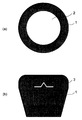
図5は、本発明の実施の形態3に係る通気栓の外観図である。基本的には、実施の形態1に係る通気栓と同様のものであるが、実施の形態3では、開口部3を4つ備えている(そのうち、図5に示されている開口部は、開口部3a、3bの2つである)。さらに、実施の形態3では、筒状部材1の側面全周を360°としたとき、隣り合う開口部同士の間の非開口部分がいずれも90°以下となるように設計されている。すなわち、図5に示すように開口部3aと開口部3bとの間の非開口部分が、筒状部材1の中心軸から見てα(90°以下)の拡がり角となるように設計されている。このような構成とすることにより、開口部3aから確認する限りにおいて通気膜2が適切に固定されていれば、仮に非開口部分における通気膜2に多少のズレが生じていたとしても通気栓の機能には問題がないレベルであると判断することができる。
図5は、本発明の実施の形態3に係る通気栓の外観図である。基本的には、実施の形態1に係る通気栓と同様のものであるが、実施の形態3では、開口部3を4つ備えている(そのうち、図5に示されている開口部は、開口部3a、3bの2つである)。さらに、実施の形態3では、筒状部材1の側面全周を360°としたとき、隣り合う開口部同士の間の非開口部分がいずれも90°以下となるように設計されている。すなわち、図5に示すように開口部3aと開口部3bとの間の非開口部分が、筒状部材1の中心軸から見てα(90°以下)の拡がり角となるように設計されている。このような構成とすることにより、開口部3aから確認する限りにおいて通気膜2が適切に固定されていれば、仮に非開口部分における通気膜2に多少のズレが生じていたとしても通気栓の機能には問題がないレベルであると判断することができる。
なお、実施の形態3においては、開口部3の数を4つとした場合について説明したが、開口部3の延在範囲や通気栓の大きさ等によって適宜調整することは可能であり、例えば、2つ以上存在することが好ましい。
(実施の形態4)
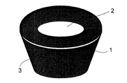
図6は、本発明の実施の形態4に係る通気栓の外観図である。基本的には、実施の形態1~3に係る通気栓と同様のものであるが、実施の形態4では、開口部3が筒状部材1側面の全周にわたって形成されている。これにより、あらゆる方向から通気膜2の形成状態を確認することができる。
図6は、本発明の実施の形態4に係る通気栓の外観図である。基本的には、実施の形態1~3に係る通気栓と同様のものであるが、実施の形態4では、開口部3が筒状部材1側面の全周にわたって形成されている。これにより、あらゆる方向から通気膜2の形成状態を確認することができる。
筒状部材1のうち通気膜2の下側に存在する部分を「下部筒状部材」、上側に存在する部分を「上部筒状部材」とした場合において、下部筒状部材の内径と上部筒状部材の内径が略同一であり、下部筒状部材の外径と上部筒状部材の外径が略同一であることが好ましい。その理由は、内径又は外径が大きく異なる場合は、上部筒状部材と下部筒状部材の熱収縮の程度差によりストレスが生じ、通気栓に変形が生じてしまう可能性があるからである。上記内径および外径は、通気膜2に接する部分において特定されるものとする。
なお、後述するように通気膜2に補強層を積層して用いる場合は、補強層が通気膜2から剥離する可能性を低くするために、筒状部材1のうち通気膜2の下側に存在する部分と上側に存在する部分とがより広い面積で繋がっている通気栓(例えば図1~3)を用いることが好ましい。
(実施の形態5)
図7の(a)は、本発明の実施の形態5に係る通気栓の平面図(上面図)であり、(b)は、同側面図である。実施の形態5では、筒状部材1において、通気膜2の周縁部を挟持する面に凹凸形状を有している。後述するように、通気膜2には膜の方向によって異方性が存在する場合があるため、凹凸形状の付与により通気膜2の方向性を表示することができる。また、凹凸形状により、通気膜2と筒状部材1とがより強固に固定される。
図7の(a)は、本発明の実施の形態5に係る通気栓の平面図(上面図)であり、(b)は、同側面図である。実施の形態5では、筒状部材1において、通気膜2の周縁部を挟持する面に凹凸形状を有している。後述するように、通気膜2には膜の方向によって異方性が存在する場合があるため、凹凸形状の付与により通気膜2の方向性を表示することができる。また、凹凸形状により、通気膜2と筒状部材1とがより強固に固定される。
(実施の形態6)
図8の(a)は、本発明の実施の形態6に係る通気栓の平面図(上面図)であり、(b)は、同側面図である。実施の形態6においても、通気膜2の周縁部を挟持する面に凹凸形状を有している。実施の形態5の場合と同様に、通気膜2には膜の方向によって異方性が存在する場合があるため、凹凸形状の付与により通気膜2の方向性を表示することができる。本実施の形態では、通気膜2の通気面にも凹凸形状が付与されるように構成しているため、通気栓の上面側から見ても通気膜2の方向性を確認することができる。また、このように通気面に凹凸形状が付与されている場合、通気膜2の通気面積が増えるため、通気栓の圧力損失が低減される。また、実施の形態5の場合と同様に通気膜2と筒状部材1とがより強固に固定される。
図8の(a)は、本発明の実施の形態6に係る通気栓の平面図(上面図)であり、(b)は、同側面図である。実施の形態6においても、通気膜2の周縁部を挟持する面に凹凸形状を有している。実施の形態5の場合と同様に、通気膜2には膜の方向によって異方性が存在する場合があるため、凹凸形状の付与により通気膜2の方向性を表示することができる。本実施の形態では、通気膜2の通気面にも凹凸形状が付与されるように構成しているため、通気栓の上面側から見ても通気膜2の方向性を確認することができる。また、このように通気面に凹凸形状が付与されている場合、通気膜2の通気面積が増えるため、通気栓の圧力損失が低減される。また、実施の形態5の場合と同様に通気膜2と筒状部材1とがより強固に固定される。
2.通気栓の各構成要素の詳細な説明
次に、本発明の通気栓における筒状部材1および通気膜2の詳細(好ましい材料等)について説明する。
次に、本発明の通気栓における筒状部材1および通気膜2の詳細(好ましい材料等)について説明する。
(1)筒状部材
筒状部材1は、上述したように電気装置の筐体等に通気栓を差し込む用途を考慮すれば、弾力性のある樹脂で構成されることが好ましい。樹脂の例としては、サントプレーン、ミナストマー等のオレフィン系を主とした弾性樹脂、エチレンプロピレンゴム(EPDM)、アクリルゴム、シリコンゴム、フッ素ゴムなどのゴム系若しくはゴム代替の弾性樹脂、ポリプロピレン(PP)を含むものが望ましい。筒状部材1は、上述したように通気膜2を上下から挟み込んだ構造を有しているが、通気膜2の上側と下側とで異なる種類の材料を用いてもよい。電気装置の一部に本発明の通気栓を容易に差し込むためには、筒状部材1の硬度(JIS K 6253)は100度以下、より好ましくは80度以下である。筒状部材のシール性を担保するためには、10度以上、より好ましくは40度以上である。ゴム硬度の計測には、デュロメータ(株式会社島津製作所製:DUROMETER A)が用いられる。
筒状部材1は、上述したように電気装置の筐体等に通気栓を差し込む用途を考慮すれば、弾力性のある樹脂で構成されることが好ましい。樹脂の例としては、サントプレーン、ミナストマー等のオレフィン系を主とした弾性樹脂、エチレンプロピレンゴム(EPDM)、アクリルゴム、シリコンゴム、フッ素ゴムなどのゴム系若しくはゴム代替の弾性樹脂、ポリプロピレン(PP)を含むものが望ましい。筒状部材1は、上述したように通気膜2を上下から挟み込んだ構造を有しているが、通気膜2の上側と下側とで異なる種類の材料を用いてもよい。電気装置の一部に本発明の通気栓を容易に差し込むためには、筒状部材1の硬度(JIS K 6253)は100度以下、より好ましくは80度以下である。筒状部材のシール性を担保するためには、10度以上、より好ましくは40度以上である。ゴム硬度の計測には、デュロメータ(株式会社島津製作所製:DUROMETER A)が用いられる。
通気膜2を含む平面からみた筒状部材1の端部(突起部)の高さは、筒状部材1の貫通孔1aの直径に対し、5~200%が好ましく、より好ましくは10~100%、さらに好ましくは15~50%とすることが望ましい。
(2)通気膜
通気膜2の構成材料としては、ポリエチレン、ポリプロピレン、ポリスチレン、ポリイミド等を使用することができるが、好ましくは防水性に優れたフッ素樹脂、更に好ましくは、多孔質ポリテトラフルオロエチレン(多孔質PTFE)のフィルムを用いることが推奨される。通気膜2の微視的形状としては、ネット状、メッシュ状、多孔質のものを用いることができる。多孔質PTFEフィルムは、防滴性に優れ、水滴、油滴、塵埃の侵入を防止しつつ電気装置の内外に通気性を持たせる用途に適している。
通気膜2の構成材料としては、ポリエチレン、ポリプロピレン、ポリスチレン、ポリイミド等を使用することができるが、好ましくは防水性に優れたフッ素樹脂、更に好ましくは、多孔質ポリテトラフルオロエチレン(多孔質PTFE)のフィルムを用いることが推奨される。通気膜2の微視的形状としては、ネット状、メッシュ状、多孔質のものを用いることができる。多孔質PTFEフィルムは、防滴性に優れ、水滴、油滴、塵埃の侵入を防止しつつ電気装置の内外に通気性を持たせる用途に適している。
多孔質PTFEフィルムは、PTFEのファインパウダーを成形助剤と混合することにより得られるペーストの成形体から、成形助剤を除去した後、高温高速度で延伸、さらに必要に応じて焼成することにより得られるものである。一軸延伸の場合、ノード(折り畳み結晶)が延伸方向に直角に細い島状となっていて、このノード間を繋ぐようにすだれ状にフィブリル(折り畳み結晶が延伸により解けて引出された直鎖状の分子束)が延伸方向に配向している。そして、フィブリル間、又はフィブリルとノードとで画される空間が空孔となった繊維質構造となっている。また、二軸延伸の場合には、フィブリルが放射状に広がり、フィブリルを繋ぐノードが島状に点在して、フィブリルとノードとで画された空間が多数存在するクモの巣状の繊維質構造となっている。
通気膜2は、一軸延伸多孔質PTFEフィルムであっても良いし、二軸延伸多孔質PTFEフィルムであってもよい。
通気膜2は、単独で(単層で)使用できるだけの強度を有することが好ましいが、不織布、織物や編物等のネット等、伸縮性を持ち、好ましくは120℃の高温に耐え得る通気性の補強層(補強膜)と積層して使用してもよい。
通気膜2の物理的特性としては、1kPa以上、より好ましくは10kPa以上の耐水圧と、1000秒以下、より好ましくは100秒以下の透気度(JIS P 8117)を備えることが望ましい。
通気膜2は、その細孔内表面に撥液性を付与されているのが好ましい。通気膜2に撥液性を持たせることで、体脂や機械油、水滴などの様々な汚染物が、通気膜の細孔内に浸透若しくは保持されるのを抑制できる。これらの汚染物質は、通気膜の捕集特性や通気特性を低下させ、通気膜としての機能を損なわせる原因となる。なお、筒状部材1の表面全体に撥液性を付与してもよい。
なお、特許請求の範囲及び本明細書において、撥液性を付与する方法としては、撥液性材料を使用する、もしくは、撥液剤を添加することでも可能であり、この場合の「撥液」とは、液体をはじく性質乃至は機能を指すものであるとし、「撥液剤」には、「撥水剤」、「撥油剤」、「撥水撥油剤」等を含むものとする。以下、撥水撥油性ポリマーを例に挙げて説明する。
撥水撥油性ポリマーとしては、含フッ素側鎖を有するポリマーを用いることができる。撥水撥油性ポリマーおよびそれを多孔質PTFEフィルムに複合化する方法の詳細についてはWO94/22928号公報などに開示されている。
(3)その他
筒状部材1と通気膜2との接合には、後述するように溶融した筒状部材1に通気膜2を圧着させる方法を用いることができるし、両面粘着テープを使用することもできるが本発明の必須の構成要素ではない。その両面粘着テープには、ポリエチレン不織布、ポリプロピレン不織布、ナイロン不織布等を芯材とした不織布基材両面粘着テープ、PET基材両面粘着テープ、ポリイミド基材両面粘着テープ、ナイロン基材両面粘着テープ、発泡体(例えば、ウレタンフォーム、シリコーンフォーム、アクリルフォーム、ポリエチレンフォーム)基材両面粘着テープ、基材レス両面粘着テープなど様々なタイプのものを用いることができる。
筒状部材1と通気膜2との接合には、後述するように溶融した筒状部材1に通気膜2を圧着させる方法を用いることができるし、両面粘着テープを使用することもできるが本発明の必須の構成要素ではない。その両面粘着テープには、ポリエチレン不織布、ポリプロピレン不織布、ナイロン不織布等を芯材とした不織布基材両面粘着テープ、PET基材両面粘着テープ、ポリイミド基材両面粘着テープ、ナイロン基材両面粘着テープ、発泡体(例えば、ウレタンフォーム、シリコーンフォーム、アクリルフォーム、ポリエチレンフォーム)基材両面粘着テープ、基材レス両面粘着テープなど様々なタイプのものを用いることができる。
3.通気栓の使用例
本発明の通気栓は、例えば内部に電子部品を収納するケース(筐体)に直接又は間接に取り付けられるが、取り付け部位の形状によって筒状部材1の形状は種々変更され得る。
本発明の通気栓は、例えば内部に電子部品を収納するケース(筐体)に直接又は間接に取り付けられるが、取り付け部位の形状によって筒状部材1の形状は種々変更され得る。
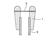
(使用例1)
図9に示すように、通気栓が通気パイプ6の先端部に取り付けられる場合には、筒状部材1の内側に通気パイプ6の先端が当接する段差部を設けてもよい。また、図示はしていないが、筒状部材1の形状を通気パイプ6の内側と外側の両方に勘合するように形成すれば、通気栓の取り付け強度が高くなる。
図9に示すように、通気栓が通気パイプ6の先端部に取り付けられる場合には、筒状部材1の内側に通気パイプ6の先端が当接する段差部を設けてもよい。また、図示はしていないが、筒状部材1の形状を通気パイプ6の内側と外側の両方に勘合するように形成すれば、通気栓の取り付け強度が高くなる。
(使用例2)
図10に示すように、通気栓が上記ケース(筐体)7の一部に設けられた有底穴に取り付けられてもよい。当該穴との勘合性を高めることによりシールド性、取り付け強度に優れた通気栓を作製することができる。
図10に示すように、通気栓が上記ケース(筐体)7の一部に設けられた有底穴に取り付けられてもよい。当該穴との勘合性を高めることによりシールド性、取り付け強度に優れた通気栓を作製することができる。
(使用例3)
使用例2の場合と同様に通気栓が上記筐体7の穴に取り付けられる場合には、筒状部材1の側面に開口部3を挟んで少なくとも2つの環状の凸部5を形成してもよい。通気栓と穴の内壁面との勘合性及びシールド性(密封性)を高めるために凸部5を1つ設けることは通常考えられるが、通気栓の勘合性及びシールド性を一層高めるためには、凸部5を2つ設けることが好ましい。例えば、通気栓と穴との間に異物やゴミが挟み込まれた場合、または、穴に傷がある場合には通気栓の勘合性が悪く、気体リークが発生する可能性がある。その点、凸部5を2つ設けると気体リークの可能性は減少する。
使用例2の場合と同様に通気栓が上記筐体7の穴に取り付けられる場合には、筒状部材1の側面に開口部3を挟んで少なくとも2つの環状の凸部5を形成してもよい。通気栓と穴の内壁面との勘合性及びシールド性(密封性)を高めるために凸部5を1つ設けることは通常考えられるが、通気栓の勘合性及びシールド性を一層高めるためには、凸部5を2つ設けることが好ましい。例えば、通気栓と穴との間に異物やゴミが挟み込まれた場合、または、穴に傷がある場合には通気栓の勘合性が悪く、気体リークが発生する可能性がある。その点、凸部5を2つ設けると気体リークの可能性は減少する。
また、開口部3を挟んで2つ設けることにより、筒状部材1と凸部5と穴とで密閉空間が形成される。通気膜2の面内方向に沿って流れる気体が開口部3から抜けることによって、密閉空間の圧力変化を制御できる。そのため、開口部3のシールド性が安定する。
4.通気栓の製造プロセス例
以下、本発明の通気栓の製造に適用し得るプロセス例について説明する。
以下、本発明の通気栓の製造に適用し得るプロセス例について説明する。
(1)射出成型(インジェクションモールディング)
溶融させた熱可塑性樹脂を所定の凹状に加工した金型内に圧入し、その後、熱可塑性樹脂を冷却することで通気栓の成型品を得る方法である。工程手順は、図12(a)~(b)の工程断面図によって示される。
溶融させた熱可塑性樹脂を所定の凹状に加工した金型内に圧入し、その後、熱可塑性樹脂を冷却することで通気栓の成型品を得る方法である。工程手順は、図12(a)~(b)の工程断面図によって示される。
まず、図12(a)に示すように第1の金型11及び第2の金型12を向かい合わせて密着させることにより、金型の内部に筒状部材1の形状の空洞を形成する。第1の金型11及び第2の金型12の間には、予め通気膜2を挟持しておく。
次に、図12(b)に示すように、注入口13から溶融させた熱可塑性樹脂を第1の金型11内に注入する。溶融樹脂の注入の際、樹脂の注入圧力で通気膜2(例えばPTFE多孔質体)の空隙部分に樹脂を含侵させ、さらに樹脂を冷却し、硬化させることで樹脂(すなわち成型された筒状部材1)と通気膜2とがアンカー効果によって強固に固着された状態となる。
最後に、第1の金型11及び第2の金型12を脱型するとともに、余分の通気膜2をカットすることにより、筒状部材1と通気膜2で構成された通気栓を得ることができる。
なお、ここでは1つの筒状部材1に対して1枚の通気膜2を配置して1つの通気栓を成型する工程を例にして説明したが、複数の筒状部材1を成型できる金型を用い、1枚の通気膜2を配置して複数の通気栓を成型し、その後に、個々の筒状部材1の側面において通気膜2をカットすることにより、製造効率のよい並列処理式の製造工程を実現できる。
(2)圧縮成型(コンプレッションモールディング)
工程手順としては上述の射出成型と同様であるが、圧縮成型では加硫によって硬化する樹脂(上記EPDM等のゴム系材料)を高圧のプレス機で所定形状に加工した金型内に圧入し、その後、加硫によって樹脂を硬化させることで通気栓の成型品を得る方法である。樹脂の注入圧力で、通気膜2(例えばPTFE多孔質体)の空隙部分に樹脂を含侵させ、樹脂を冷却・硬化することでアンカー効果による強固な固着効果を得ることができる。
工程手順としては上述の射出成型と同様であるが、圧縮成型では加硫によって硬化する樹脂(上記EPDM等のゴム系材料)を高圧のプレス機で所定形状に加工した金型内に圧入し、その後、加硫によって樹脂を硬化させることで通気栓の成型品を得る方法である。樹脂の注入圧力で、通気膜2(例えばPTFE多孔質体)の空隙部分に樹脂を含侵させ、樹脂を冷却・硬化することでアンカー効果による強固な固着効果を得ることができる。
1 筒状部材
1a 貫通孔
2 通気膜
3、3a、3b 開口部
5 環状部材
6 通気パイプ
7 ケース(筐体)
11 第1の金型
12 第2の金型
13 注入口
1a 貫通孔
2 通気膜
3、3a、3b 開口部
5 環状部材
6 通気パイプ
7 ケース(筐体)
11 第1の金型
12 第2の金型
13 注入口
Claims (12)
- 貫通孔を有する筒状部材と、前記貫通孔を横断する通気膜とを備えた通気栓であって、前記通気膜の周縁部は前記筒状部材により挟持され、前記筒状部材の側面には前記通気膜の周縁端部を視認できる開口部が形成されていることを特徴とする通気栓。
- 下記(1)~(3)の条件のうち、少なくとも1つを満足する請求項1に記載の通気栓。
前記筒状部材と前記通気膜の色相は、色相の尺度である色相環の全周を360°とした場合に、互いに15°以上離れている。 (1)
前記筒状部材と前記通気膜は、明度が1度以上異なる。 (2)
前記筒状部材と前記通気膜は、彩度が2度以上異なる。 (3) - 前記開口部が前記筒状部材側面の全周にわたり形成されている請求項1または2に記載の通気栓。
- 前記通気膜および/または前記筒状部材が、蓄光剤、蛍光剤、光反射材のいずれか1種以上を含有している請求項1~3のいずれかに記載の通気栓。
- 前記筒状部材は、前記通気膜の周縁部を挟持する面に凹凸形状を有している請求項1~4のいずれかに記載の通気栓。
- 前記筒状部材の側面には、前記開口部を挟んで少なくとも2つの環状の凸部が形成されている請求項1~5のいずれかに記載の通気栓。
- 前記開口部を2つ以上有し、前記筒状部材の側面全周を360°としたとき、隣り合う開口部同士の間の非開口部分をいずれも90°以下とする請求項1~6のいずれかに記載の通気栓。
- 前記通気膜の片面または両面に補強膜が形成されている請求項1~7のいずれかに記載の通気栓。
- 前記通気膜が撥液性を有する請求項1~8のいずれかに記載の通気栓。
- 前記開口部から視認される前記通気膜の周縁端部が撥液性を有する請求項9に記載の通気栓。
- 前記通気膜が多孔質ポリテトラフルオロエチレン膜である請求項1~10のいずれかに記載の通気栓。
- 請求項1~11のいずれかに記載された通気栓の側面像を撮影する工程と、該側面像から、前記通気膜が適切に固定されているか否かを判定する工程とを含む通気栓の検査方法。
Applications Claiming Priority (2)
| Application Number | Priority Date | Filing Date | Title |
|---|---|---|---|
| JP2009-140889 | 2009-06-12 | ||
| JP2009140889A JP5563245B2 (ja) | 2009-06-12 | 2009-06-12 | 通気栓及び通気栓の検査方法 |
Publications (1)
| Publication Number | Publication Date |
|---|---|
| WO2010143624A1 true WO2010143624A1 (ja) | 2010-12-16 |
Family
ID=43308879
Family Applications (1)
| Application Number | Title | Priority Date | Filing Date |
|---|---|---|---|
| PCT/JP2010/059687 Ceased WO2010143624A1 (ja) | 2009-06-12 | 2010-06-08 | 通気栓及び通気栓の検査方法 |
Country Status (2)
| Country | Link |
|---|---|
| JP (1) | JP5563245B2 (ja) |
| WO (1) | WO2010143624A1 (ja) |
Cited By (5)
| Publication number | Priority date | Publication date | Assignee | Title |
|---|---|---|---|---|
| CN102407732A (zh) * | 2011-10-26 | 2012-04-11 | 东风汽车股份有限公司 | 吊管式汽车后桥通气塞 |
| WO2013080494A1 (ja) * | 2011-11-28 | 2013-06-06 | 日東電工株式会社 | 通気部材 |
| WO2013183211A1 (ja) * | 2012-06-08 | 2013-12-12 | 日東電工株式会社 | 防水通気部材及び通気構造 |
| JPWO2016006615A1 (ja) * | 2014-07-07 | 2017-06-01 | 国立大学法人 東京大学 | バルブ、流体デバイス、流体制御方法及びバルブの製造方法 |
| CN111122071A (zh) * | 2019-12-31 | 2020-05-08 | 广东罗曼智能科技股份有限公司 | 一种电动牙刷的气密性检测装置 |
Families Citing this family (2)
| Publication number | Priority date | Publication date | Assignee | Title |
|---|---|---|---|---|
| JP6560001B2 (ja) * | 2015-04-06 | 2019-08-14 | 積水樹脂株式会社 | フィルム巻き上げパイプの製造方法 |
| JP6726984B2 (ja) * | 2016-02-29 | 2020-07-22 | フクダ電子株式会社 | パルスオキシメータの防水検査構造 |
Citations (6)
| Publication number | Priority date | Publication date | Assignee | Title |
|---|---|---|---|---|
| JPH0276277U (ja) * | 1988-07-15 | 1990-06-12 | ||
| EP0816043A1 (de) * | 1996-07-03 | 1998-01-07 | W.L. GORE & ASSOCIATES GmbH | Verfahren zur Herstellung eines Verschlusselements in Form eines Kunststoff-Spritzgussteils sowie ein durch dieses hergestelltes Verschlusselement |
| WO2001096197A2 (de) * | 2000-06-16 | 2001-12-20 | Utz Kador | Verschlusseinrichtung |
| WO2006123717A1 (ja) * | 2005-05-18 | 2006-11-23 | Nitto Denko Corporation | 通気部材とこれを用いた通気筐体 |
| JP2006315725A (ja) * | 2005-05-13 | 2006-11-24 | Tokai Kogyo Co Ltd | 通気部品及び通気部品の製造方法並びに防水性通気膜 |
| JP2008237949A (ja) * | 2007-03-23 | 2008-10-09 | Nitto Denko Corp | 防水通気フィルタ、防水通気部材および筐体 |
Family Cites Families (6)
| Publication number | Priority date | Publication date | Assignee | Title |
|---|---|---|---|---|
| JPS63153410U (ja) * | 1987-03-30 | 1988-10-07 | ||
| JP2002143624A (ja) * | 2000-11-14 | 2002-05-21 | Saint-Gobain Norton Kk | 通気フィルターおよびフィルター付き容器 |
| JP2003090721A (ja) * | 2001-09-19 | 2003-03-28 | Bridgestone Corp | ゴム部材の検出方法、及びゴム部材の貼付方法 |
| JP2006085100A (ja) * | 2004-09-17 | 2006-03-30 | Ricoh Co Ltd | 構成部品判別装置、生産システム、及び画像形成装置 |
| JP4879475B2 (ja) * | 2004-11-19 | 2012-02-22 | 日東電工株式会社 | 通気フィルタ部材およびそれを利用した通気筐体 |
| JP2009007439A (ja) * | 2007-06-27 | 2009-01-15 | Nitto Denko Corp | 撥液性を有する通気膜の製造方法と撥液性を有する通気膜ならびに通気部材 |
-
2009
- 2009-06-12 JP JP2009140889A patent/JP5563245B2/ja active Active
-
2010
- 2010-06-08 WO PCT/JP2010/059687 patent/WO2010143624A1/ja not_active Ceased
Patent Citations (6)
| Publication number | Priority date | Publication date | Assignee | Title |
|---|---|---|---|---|
| JPH0276277U (ja) * | 1988-07-15 | 1990-06-12 | ||
| EP0816043A1 (de) * | 1996-07-03 | 1998-01-07 | W.L. GORE & ASSOCIATES GmbH | Verfahren zur Herstellung eines Verschlusselements in Form eines Kunststoff-Spritzgussteils sowie ein durch dieses hergestelltes Verschlusselement |
| WO2001096197A2 (de) * | 2000-06-16 | 2001-12-20 | Utz Kador | Verschlusseinrichtung |
| JP2006315725A (ja) * | 2005-05-13 | 2006-11-24 | Tokai Kogyo Co Ltd | 通気部品及び通気部品の製造方法並びに防水性通気膜 |
| WO2006123717A1 (ja) * | 2005-05-18 | 2006-11-23 | Nitto Denko Corporation | 通気部材とこれを用いた通気筐体 |
| JP2008237949A (ja) * | 2007-03-23 | 2008-10-09 | Nitto Denko Corp | 防水通気フィルタ、防水通気部材および筐体 |
Cited By (10)
| Publication number | Priority date | Publication date | Assignee | Title |
|---|---|---|---|---|
| CN102407732A (zh) * | 2011-10-26 | 2012-04-11 | 东风汽车股份有限公司 | 吊管式汽车后桥通气塞 |
| WO2013080494A1 (ja) * | 2011-11-28 | 2013-06-06 | 日東電工株式会社 | 通気部材 |
| JP2013114829A (ja) * | 2011-11-28 | 2013-06-10 | Nitto Denko Corp | 通気部材 |
| CN103958964A (zh) * | 2011-11-28 | 2014-07-30 | 日东电工株式会社 | 透气部件 |
| EP2787277A4 (en) * | 2011-11-28 | 2015-12-23 | Nitto Denko Corp | VENTILATION ELEMENT |
| US9255719B2 (en) | 2011-11-28 | 2016-02-09 | Nitto Denko Corporation | Ventilation member |
| CN103958964B (zh) * | 2011-11-28 | 2017-03-29 | 日东电工株式会社 | 透气部件 |
| WO2013183211A1 (ja) * | 2012-06-08 | 2013-12-12 | 日東電工株式会社 | 防水通気部材及び通気構造 |
| JPWO2016006615A1 (ja) * | 2014-07-07 | 2017-06-01 | 国立大学法人 東京大学 | バルブ、流体デバイス、流体制御方法及びバルブの製造方法 |
| CN111122071A (zh) * | 2019-12-31 | 2020-05-08 | 广东罗曼智能科技股份有限公司 | 一种电动牙刷的气密性检测装置 |
Also Published As
| Publication number | Publication date |
|---|---|
| JP5563245B2 (ja) | 2014-07-30 |
| JP2010286378A (ja) | 2010-12-24 |
Similar Documents
| Publication | Publication Date | Title |
|---|---|---|
| JP5563245B2 (ja) | 通気栓及び通気栓の検査方法 | |
| JP5622369B2 (ja) | 通気栓 | |
| JP6130183B2 (ja) | 通気部材 | |
| CN104080305B (zh) | 防水通气结构、防水通气构件及防水通气膜 | |
| KR100638981B1 (ko) | 통기 부재와, 이 통기 부재를 포함하는 통기 하우징 | |
| KR100685555B1 (ko) | 통기 부재와, 이 통기 부재를 포함하는 통기 하우징 | |
| US8246726B2 (en) | Ventilation member | |
| CN104075301B (zh) | 透气构件 | |
| JP6130182B2 (ja) | 通気部材 | |
| JP6431451B2 (ja) | 通気部材付き樹脂部材及びその製造方法、筐体並びにセンサ | |
| US20150114090A1 (en) | Mobile device and waterproof test method | |
| CN104540887B (zh) | 聚四氟乙烯黑色多孔膜、其制造方法、使用该多孔膜的透气膜和透气构件 | |
| US20140047981A1 (en) | Ventilation unit | |
| KR20100103557A (ko) | 폴리테트라플루오로에틸렌 다공질막과 그 제조 방법, 및 방수 통기 필터 | |
| TWI674188B (zh) | 氣體透過構件及其製造方法 | |
| TW201924364A (zh) | 防水透音構件及具備其之電子機器 | |
| WO2013031085A1 (ja) | 通気機能を有する接合部材及びそれを用いた接合構造 | |
| JP6538863B2 (ja) | ベント装置 | |
| JP7731527B1 (ja) | 通気膜、通気部材及び発光デバイス | |
| CN206247260U (zh) | 灯具及其密封光学罩 | |
| CN209042007U (zh) | 照明装置 | |
| CN121697311A (zh) | 具有椭圆形及岛形微观特征的ePTFE微孔膜贴片组件及其在汽车电气设备中的应用 |
Legal Events
| Date | Code | Title | Description |
|---|---|---|---|
| 121 | Ep: the epo has been informed by wipo that ep was designated in this application |
Ref document number: 10786155 Country of ref document: EP Kind code of ref document: A1 |
|
| NENP | Non-entry into the national phase |
Ref country code: DE |
|
| 122 | Ep: pct application non-entry in european phase |
Ref document number: 10786155 Country of ref document: EP Kind code of ref document: A1 |