WO2010146659A1 - Appareil d'émission optique - Google Patents
Appareil d'émission optique Download PDFInfo
- Publication number
- WO2010146659A1 WO2010146659A1 PCT/JP2009/060940 JP2009060940W WO2010146659A1 WO 2010146659 A1 WO2010146659 A1 WO 2010146659A1 JP 2009060940 W JP2009060940 W JP 2009060940W WO 2010146659 A1 WO2010146659 A1 WO 2010146659A1
- Authority
- WO
- WIPO (PCT)
- Prior art keywords
- optical
- light
- signal
- port
- transmission
- Prior art date
- Legal status (The legal status is an assumption and is not a legal conclusion. Google has not performed a legal analysis and makes no representation as to the accuracy of the status listed.)
- Ceased
Links
Images



Classifications
-
- H—ELECTRICITY
- H04—ELECTRIC COMMUNICATION TECHNIQUE
- H04B—TRANSMISSION
- H04B10/00—Transmission systems employing electromagnetic waves other than radio-waves, e.g. infrared, visible or ultraviolet light, or employing corpuscular radiation, e.g. quantum communication
- H04B10/07—Arrangements for monitoring or testing transmission systems; Arrangements for fault measurement of transmission systems
- H04B10/071—Arrangements for monitoring or testing transmission systems; Arrangements for fault measurement of transmission systems using a reflected signal, e.g. using optical time domain reflectometers [OTDR]
-
- H—ELECTRICITY
- H04—ELECTRIC COMMUNICATION TECHNIQUE
- H04B—TRANSMISSION
- H04B10/00—Transmission systems employing electromagnetic waves other than radio-waves, e.g. infrared, visible or ultraviolet light, or employing corpuscular radiation, e.g. quantum communication
- H04B10/40—Transceivers
-
- H—ELECTRICITY
- H04—ELECTRIC COMMUNICATION TECHNIQUE
- H04B—TRANSMISSION
- H04B2210/00—Indexing scheme relating to optical transmission systems
- H04B2210/08—Shut-down or eye-safety
Definitions
- the present invention relates to an optical transmission apparatus that performs single-core bidirectional optical transmission.
- the transmission distance of optical communication systems has been increased, and there has been a demand for higher output of optical transmitters and higher sensitivity of optical receivers.
- the single-core bidirectional optical communication system has been conventionally used in a short distance such as a subscriber system.
- it has been introduced also in a trunk system, so that high output is achieved.
- the higher the output of the optical transmitter the greater the risk that the laser beam will be exerted on the human body when the optical connector is disconnected. Therefore, it is important to take measures for safety.
- Patent Document 1 has been proposed as a conventional technique for detecting disconnection of an optical connector.
- the present invention has been made in view of the above points, and provides an optical transmission device that monitors the connection state of an optical connector and automatically stops signal light output when the connection state is incomplete.
- the purpose is to do.
- the optical transmission device includes an optical port for one-core bidirectional transmission connected by an optical connector connected to an optical fiber, an optical transmitter that transmits signal light of a first wavelength via the optical port, and the optical An optical receiver that receives the signal light of the second wavelength through the port, an optical filter that filters light incident on the device through the optical port, and a control that controls the optical output level of the optical transmitter A part.
- the optical filter transmits the reflected return light of the signal light having the first wavelength reflected by the optical port toward the control unit, and transmits the signal light having the second wavelength to the optical receiving unit.
- the control unit recognizes that the connection state of the optical connector is incomplete and stops the optical output of the optical transmitter.
- FIG. 1 is a diagram illustrating a configuration example of an optical transmission apparatus.
- the optical transmission device 10 includes an optical port P, an optical transmitter 11, an optical receiver 12, a half mirror 13, a reflective wavelength selection filter (corresponding to an optical filter) 14, and wavelength selection filters 15a and 15b.
- the control unit 16 is configured.
- the optical port P is an optical transmission / reception port for single-core bidirectional transmission provided with an optical socket to which an optical connector C connected to the optical fiber f is connected.
- the optical transmitter 11 transmits the signal light having the first wavelength via the optical port P.
- the optical receiver 12 receives the signal light of the second wavelength via the optical port P.
- the half mirror 13 is disposed between the optical transmitter 11 and the optical port P.
- the signal light having the first wavelength transmitted from the optical transmitter 11 is transmitted to the optical port P and incident through the optical port P. Light reflects.
- the reflection-type wavelength selection filter 14 transmits the reflected return light of the first wavelength signal light reflected by the optical port P toward the control unit 16 and the second wavelength signal light toward the optical receiver 12. To Penetrate.
- the wavelength selection filter 15a transmits only the signal light having the first wavelength
- the wavelength selection filter 15b transmits only the signal light having the second wavelength.
- the control unit 16 controls the optical output level of the optical transmitter 11. Further, when receiving the reflected return light having the first wavelength of a certain level, the control unit 16 recognizes that the connection state of the optical connector C is incomplete and stops the optical output of the optical transmitter 11.
- the incomplete connection between the optical connector C and the optical port P means that the optical connector C is not normally connected to the optical port P. For example, light leaks from the optical port P. This is a case where a state is generated. Further, a state where the optical connector C is disconnected from the optical port P during operation of the apparatus (optical connector disconnected) is also included.
- the operation will be described.
- the case where the connection state between the optical connector C and the optical port P is normal and the case where the connection state is incomplete will be described separately. It is assumed that the first wavelength output from the optical transmission device 10 is 1.31 ⁇ m and the second wavelength received by the optical transmission device 10 is 1.49 ⁇ m.
- the optical transmitter 11 outputs 1.31 ⁇ m signal light, and the half mirror 13 transmits 1.31 ⁇ m signal light.
- the 1.31 ⁇ m signal light is transmitted through the optical port P to the opposite device through the optical fiber f.
- 1.49 ⁇ m signal light from the opposite device that has flowed through the optical fiber f enters the optical transmission device 10 via the optical port P.
- the incident 1.49 ⁇ m signal light is reflected by the half mirror 13 and transmitted to the reflective wavelength selection filter 14.
- the reflective wavelength selection filter 14 transmits 1.49 ⁇ m signal light, and the wavelength selection filter 15 b also transmits 1.49 ⁇ m signal light.
- the optical receiver 12 receives 1.49 ⁇ m signal light and performs predetermined optical reception processing.
- the optical transmitter 11 outputs 1.31 ⁇ m signal light, and the half mirror 13 transmits 1.31 ⁇ m signal light.
- the signal light of 1.31 ⁇ m flows toward the optical port P, but reflection (Fresnel reflection) occurs at the optical port P because the optical fiber f is not normally connected.
- the reflected return light which is the reflected light of the 1.31 ⁇ m signal light generated at the optical port P, is reflected by the half mirror 13 and transmitted to the reflective wavelength selection filter 14.
- the reflection type wavelength selection filter 14 reflects the reflected return light of 1.31 ⁇ m, and the wavelength selection filter 15a transmits the reflected return light of 1.31 ⁇ m.
- the control unit 16 receives the reflected return light of 1.31 ⁇ m, and recognizes that the connection state of the optical connector C is incomplete when the level of the reflected return light of 1.31 ⁇ m exceeds the threshold level. Then, the optical output of the optical transmitter 11 is automatically stopped. In addition to stopping the optical output, an alarm can be issued to notify the maintenance person that the connection state of the optical connector C is incomplete.
- the optical transmission device 10 is provided with the reflective wavelength selection filter 14 that transmits the signal light of 1.49 ⁇ m and reflects the signal light of 1.31 ⁇ m, and when the connection of the optical connector C is incomplete.
- the reflected return light which is 1.31 ⁇ m signal light reflected by the optical port P, is reflected by the reflective wavelength selection filter 14 and detected by the control unit 16 to stop the light output.
- FIG. 2 is a diagram illustrating a configuration example of an optical transmission apparatus.
- the optical transmission device 20 includes an optical port P, an optical transmission unit 21, an optical reception unit 22, a control unit 23, and an optical directional coupler 24.
- the optical transmitter 21 includes an LD (Laser Diode) drive unit 21a and an LD 21b
- the optical receiver 22 includes a PD (Photo Diode) 22a, a TIA (Trans Impedance Amplifier) 22b, and a reception amplifier 22c.
- the control unit 23 includes a delay unit 23a, comparators 23b-1, 23b-2, XOR 23c, and an optical level control unit 23d.
- the optical port P is an optical transmission / reception port for single-core bidirectional transmission provided with an optical socket to which an optical connector C connected to the optical fiber f is connected.
- the optical directional coupler 24 has three ports, outputs light input from the port p1 from the port p2, and outputs light input from the port p2 from the port p3.
- the optical transmission unit 21 performs E / O conversion on the transmission signal Tx, generates transmission light, and transmits it via the optical port P.
- the optical receiver 22 O / E converts the received light received via the optical port P to generate a received signal Rx.
- the control unit 23 controls the optical output level of the optical transmission unit 21.
- the control unit 23 compares the code of the transmission signal Tx and the code of the reception signal Rx, and if the code value remains the same for a certain time, the received light is an optical port due to incomplete connection of the optical connector C. Recognizing the reflected return light of the transmitted light reflected by P, the optical output of the optical transmitter 21 is stopped.
- the LD drive unit 21a superimposes the transmission signal Tx on the signal for driving the LD 21b based on the LD drive instruction from the control unit 23, and generates an LD drive signal.
- the LD 21b outputs transmission light according to the applied LD drive signal.
- the transmitted light is input to the port p1 of the optical directional coupler 24 and output from the port p2. Then, the signal is transmitted to the opposite device through the optical port f through the optical port P. At the time of optical reception, the signal light from the opposite device that has flowed through the optical fiber f enters the optical transmission device 20 via the optical port P. The incident received light is input to the port p2 of the optical directional coupler 24 and output from the port p3.
- the PD 22a O / E converts received light to generate a photocurrent.
- the TIA 22b converts the photocurrent into a voltage signal by performing I / V conversion.
- the reception amplifier 22c amplifies the voltage signal and outputs a reception signal Rx.
- the delay unit 23a delays the transmission signal Tx for a predetermined time.
- the predetermined time is the time required for the received light at the optical port P to be converted into an electrical signal by the optical receiver 22 and input to the input terminal (+) of the comparator 23b-2.
- the received light at the optical port P is input to the port p2 of the optical directional coupler 24 and output from the port p3, O / E conversion is performed by the PD 22a, I / V conversion is performed by the TIA 22b, and the reception amplifier 22c. This is the time required for the signal to be amplified and input to the input terminal (+) of the comparator 23b-2.
- the transmission signal Tx delayed by a predetermined time is input to the input terminal (+) of the comparator 23b-1, and the threshold value Vth is input to the input terminal ( ⁇ ).
- the reception signal Rx is input to the input terminal (+) of the comparator 23b-2, and the threshold value Vth is input to the input terminal ( ⁇ ).
- the comparators 23b-1 and 23b-2 output an H level voltage when a signal having a voltage higher than the threshold voltage Vth is input to the input terminal (+), and the voltage is higher than the threshold voltage Vth.
- a low signal is input to the input terminal (+)
- an L level voltage is output, and the waveform of the signal input to the input terminal (+) is shaped.
- the comparator 23b-1 outputs the transmission signal Tx1 after the waveform shaping of the transmission signal Tx
- the comparator 23b-2 outputs the reception signal Rx1 after the waveform shaping of the reception signal Rx.
- the XOR 23c outputs an XOR signal obtained by taking an exclusive OR of the output signals from the comparators 23b-1 and 23b-2.
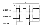
- FIG. 3 is a diagram showing the output level of the exclusive OR of the transmission signal and the reception signal.
- the optical connector C is normally connected to the optical port P, the received light at the optical port P is signal light transmitted from the opposite device.
- the code of the reception signal Rx obtained by O / E converting the received light and the code of the transmission signal Tx transmitted by the optical transmission apparatus 20 have different code values for a certain period of time and are not the same code.
- the data transmitted by the optical transmission device 10 is different from the data transmitted from the opposite device. Therefore, if the exclusive OR of the transmission signal Tx1 and the reception signal Rx1 is taken for a certain time T, a signal with a level change can be obtained.
- the code of the transmission signal Tx1 and the code of the reception signal Rx1 are not the same code but different values at a certain time T. Then, when the exclusive OR of the transmission signal Tx1 and the reception signal Rx1 is taken every time t (L level if the same sign in the width of the time t, H level if different sign), the output level of the XOR signal is constant time At T, the signal causes a level change.
- the optical level control unit 23d when the optical level control unit 23d receives the XOR signal, it detects that a level change occurs in the XOR signal at a certain time T, and the optical connector C is normal with the optical port P. Recognize that you are connected. Therefore, the optical level control unit 23d does not perform drive stop control on the LD drive unit 21a during optical reception when the optical connector C is normally connected to the optical port P.
- the transmission light is output from the optical transmission unit 21 as described above, and the transmission light passes from the port p1 to the port p2 of the optical directional coupler 24. Although the transmission light flows toward the optical port P, reflection of the transmission light occurs at the optical port P because the optical fiber f is not normally connected. The reflected return light of the transmitted light is input to the port p2 of the optical directional coupler 24 and output from the port p3.
- the PD 22a O / E converts received light (reflected return light) to generate a photocurrent.
- the TIA 22b converts the photocurrent into a voltage signal by performing I / V conversion.
- the reception amplifier 22c amplifies the voltage signal and outputs a reception signal Rx.
- the delay unit 23a delays the transmission signal Tx for a predetermined time.
- the comparator 23b-1 outputs the transmission signal Tx1 after the waveform shaping of the transmission signal Tx
- the comparator 23b-2 outputs the reception signal Rx1 after the waveform shaping of the reception signal Rx.
- the XOR 23c outputs an XOR signal obtained by taking an exclusive OR of the output signals from the comparators 23b-1 and 23b-2.
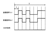
- FIG. 4 is a diagram showing the output level of the exclusive OR of the transmission signal and the reception signal.
- the code of the reception signal Rx obtained by O / E converting the reflected return light and the code of the transmission signal Tx transmitted by the optical transmission device 20 are the same signal code.
- the reception signal Rx is simply a signal obtained by O / E converting the return light of the transmission signal Tx, and is essentially the same signal). Therefore, if the exclusive OR of the transmission signal Tx1 and the reception signal Rx1 is taken for a certain time T, a signal of the same level can be obtained.
- the code of the transmission signal Tx1 and the code of the reception signal Rx1 are the same code at a certain time T. Then, when the exclusive OR of the transmission signal Tx1 and the reception signal Rx1 is taken every time t (L level if the same sign in the width of the time t, H level if different sign), the output level of the XOR signal is constant time At T, the signals are at the same level (L level).
- the optical level control unit 23d when the optical level control unit 23d receives the XOR signal, the optical level control unit 23d detects that the XOR signal is at the same level with no level change at a predetermined time T, thereby detecting the optical connector C and the optical port. Recognize that the connection with P is incomplete.
- the light level control unit 23d executes drive stop control on the LD drive unit 21a to automatically stop the light output of the LD 21b.
- an alarm can be issued to notify the maintenance person that the connection state of the optical connector C is incomplete.
- the optical transmission device 20 compares the code of the transmission signal Tx and the code of the reception signal Rx, and if the code value remains the same for a certain period of time, the currently received light is Recognizing the reflected return light of the transmitted light reflected at the optical port P due to incomplete connection of the connector C, the optical output of the optical transmitter 21 is stopped. Thereby, in the single-core bidirectional optical transmission device 20, the optical output when the optical connector C is incompletely connected can be automatically cut off, and it becomes possible to prevent danger to the human body.
- FIG. 5 is a diagram illustrating a configuration example of an optical transmission apparatus.
- the optical transmission device 30 includes an optical port P, an optical transmitter 31, an optical receiver 32, a controller 33, an optical directional coupler 34, and a low frequency signal generator 35.
- the optical transmission unit 31 includes an LD driving unit 31a and an LD 31b
- the optical reception unit 32 includes a PD 32a, a TIA 32b, and a reception amplifier 32c.
- the control unit 33 includes a band pass filter 33a and an optical level control unit 33b.
- the optical port P is an optical transmission / reception port for single-core bidirectional transmission provided with an optical socket to which an optical connector C connected to the optical fiber f is connected.
- the optical directional coupler 34 has three ports, outputs light input from the port p1 from the port p2, and outputs light input from the port p2 from the port p3.
- the low frequency signal generator 35 generates a low frequency signal 3 having a low frequency that does not affect the main signal, and transmits the low frequency signal 3 to the LD driver 31a.
- the optical transmission unit 31 superimposes the low-frequency signal 3 on the transmission signal Tx and performs E / O conversion, generates transmission light, and transmits it through the optical port P.
- the optical receiver 32 O / E converts the received light received via the optical port P to generate a received signal Rx.
- the control unit 33 controls the optical output level of the optical transmission unit 31.
- the control unit 33 detects the frequency component of the low frequency signal 3 from the reception signal Rx, the control unit 33 recognizes the reception light as reflected return light of the transmission light reflected at the optical port P due to the incomplete connection of the optical connector C. Then, the optical output of the optical transmitter 31 is stopped.
- the LD driving unit 31a superimposes the transmission signal Tx on the signal for driving the LD 31b based on the LD driving instruction from the control unit 33, and further generates the low frequency signal generated by the low frequency signal generating unit 35. 3 is superimposed to generate an LD drive signal.
- the LD 31b outputs transmission light according to the applied LD drive signal.
- the transmitted light is input to the port p1 of the optical directional coupler 34 and is output from the port p2. Then, it is transmitted to the opposite device through the optical fiber f through the optical port P. At the time of optical reception, the signal light from the opposing device that has flowed through the optical fiber f enters the optical transmission device 30 via the optical port P. The incident received light is input to the port p2 of the optical directional coupler 34 and output from the port p3.
- the PD 32a O / E converts received light to generate a photocurrent.
- the TIA 32b performs I / V conversion to convert the photocurrent into a voltage signal.
- the reception amplifier 32c amplifies the voltage signal and outputs a reception signal Rx.
- the band-pass filter 33a when receiving the reception signal Rx, the band-pass filter 33a performs a filtering process that passes the low-frequency signal 3 (the output signal of the TIA 32b may be input to the band-pass filter 33a instead of the reception signal Rx). .
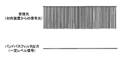
- FIG. 6 is a diagram showing the filter processing of the bandpass filter 33a.
- the figure shows the received light (signal light transmitted from the opposite device) at the optical port P and the output signal of the bandpass filter 33a when the optical connector C is normally connected to the optical port P. If the optical connector C is normally connected to the optical port P, the received light at the optical port P is signal light transmitted from the opposite device.
- the band pass filter 33a extracts the low frequency signal 3 even if the reception signal Rx is filtered. However, it only outputs a signal of a certain level.
- the optical level control unit 33b recognizes that the optical connector C is normally connected to the optical port P when receiving the constant level signal output from the band pass filter 33a. Therefore, the optical level control unit 33b does not perform drive stop control on the LD drive unit 31a during optical reception when the optical connector C is normally connected to the optical port P.
- transmission light is output from the optical transmission unit 31 as described above, and the transmission light passes from the port p1 to the port p2 of the optical directional coupler 34. Although the transmission light flows toward the optical port P, reflection of the transmission light occurs at the optical port P because the optical fiber f is not normally connected. The reflected return light of the transmitted light is input to the port p2 of the optical directional coupler 34 and output from the port p3.
- the PD 32a O / E converts received light to generate a photocurrent.
- the TIA 32b performs I / V conversion to convert the photocurrent into a voltage signal.
- the reception amplifier 32c amplifies the voltage signal and outputs a reception signal Rx.
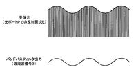
- FIG. 7 is a diagram showing filter processing of the bandpass filter 33a.
- the received light (the reflected return light of the transmitted light reflected by the optical port P) at the optical port P and the output signal of the bandpass filter 33a when the connection between the optical connector C and the optical port P is incomplete are shown. Yes.
- the connection between the optical connector C and the optical port P is incomplete, the received light at the optical port P becomes the reflected return light of the transmitted light reflected at the optical port P.
- the band pass filter 33a performs the filtering process on the reception signal Rx.
- the low frequency signal 3 is extracted and output.
- the light level control unit 33b when the light level control unit 33b receives the low frequency signal 3 output from the band pass filter 33a, the light level control unit 33b recognizes that the connection between the optical connector C and the optical port P is incomplete. .
- the light level control unit 33b performs drive stop control on the LD drive unit 31a to automatically stop the light output of the LD 31b.
- an alarm can be issued to notify the maintenance person that the connection state of the optical connector C is incomplete.
- the optical transmission device 30 generates transmission light in which the low frequency signal 3 is superimposed at the time of optical transmission, and when the frequency component of the low frequency signal 3 is detected from the reception signal Rx, the currently received reception The light is recognized as the reflected return light of the transmission light reflected at the optical port P due to the incomplete connection of the optical connector C, and the optical output of the optical transmission unit 31 is stopped. Thereby, in the single-core bidirectional optical transmission device 30, it is possible to automatically shut off the optical output when the optical connector C is incompletely connected, and to prevent danger to the human body.
Landscapes
- Physics & Mathematics (AREA)
- Electromagnetism (AREA)
- Engineering & Computer Science (AREA)
- Computer Networks & Wireless Communication (AREA)
- Signal Processing (AREA)
- Optical Communication System (AREA)
Abstract
Lorsqu'un connecteur optique n'est pas complètement connecté, la sortie optique est automatiquement coupée afin d'éviter tout risque pour le corps humain. Un port optique (P) est un port d'émission/réception optique de transmission bidirectionnelle sur fibre unique, ayant une douille optique sur laquelle un connecteur optique (C) couplé à une fibre optique (f) est connecté. Un émetteur optique (11) émet un signal lumineux d'une première longueur d'onde par l'intermédiaire du port optique (P). Un récepteur optique (12) reçoit un signal lumineux d'une seconde longueur d'onde par l'intermédiaire du port optique (P). Un filtre de sélection de longueur d'onde réfléchissante (14) réfléchit une version réfléchie en retour du signal lumineux de la première longueur d'onde réfléchie par le port optique (P) vers une partie de commande (16), tout en envoyant le signal lumineux de la seconde longueur d'onde vers le récepteur optique (12). La partie de commande (16) commande le niveau de sortie optique de l'émetteur optique (11). Après réception d'une version réfléchie en retour du signal lumineux de la première longueur d'onde ayant un niveau donné, la partie de commande (16) reconnaît une connexion incomplète du connecteur optique (C) et coupe la sortie optique de l'émetteur optique (11).
Priority Applications (1)
| Application Number | Priority Date | Filing Date | Title |
|---|---|---|---|
| PCT/JP2009/060940 WO2010146659A1 (fr) | 2009-06-16 | 2009-06-16 | Appareil d'émission optique |
Applications Claiming Priority (1)
| Application Number | Priority Date | Filing Date | Title |
|---|---|---|---|
| PCT/JP2009/060940 WO2010146659A1 (fr) | 2009-06-16 | 2009-06-16 | Appareil d'émission optique |
Publications (1)
| Publication Number | Publication Date |
|---|---|
| WO2010146659A1 true WO2010146659A1 (fr) | 2010-12-23 |
Family
ID=43355997
Family Applications (1)
| Application Number | Title | Priority Date | Filing Date |
|---|---|---|---|
| PCT/JP2009/060940 Ceased WO2010146659A1 (fr) | 2009-06-16 | 2009-06-16 | Appareil d'émission optique |
Country Status (1)
| Country | Link |
|---|---|
| WO (1) | WO2010146659A1 (fr) |
Cited By (3)
| Publication number | Priority date | Publication date | Assignee | Title |
|---|---|---|---|---|
| CN102511138A (zh) * | 2011-12-21 | 2012-06-20 | 华为技术有限公司 | 可调光收发器、无源光网络系统及设备 |
| EP2747310A1 (fr) * | 2012-12-19 | 2014-06-25 | Alcatel Lucent | Dispositif de transmission de données optiques |
| WO2020246375A1 (fr) * | 2019-06-06 | 2020-12-10 | 京セラ株式会社 | Connecteur optique pour système d'alimentation électrique à fibre optique, dispositif d'alimentation électrique et système d'alimentation électrique à fibre optique |
Citations (5)
| Publication number | Priority date | Publication date | Assignee | Title |
|---|---|---|---|---|
| JPH01119232U (fr) * | 1988-02-08 | 1989-08-11 | ||
| JPH0267027A (ja) * | 1988-09-01 | 1990-03-07 | Fujitsu Ltd | 双方向光通信回路 |
| JPH03276781A (ja) * | 1990-03-27 | 1991-12-06 | Nec Corp | レーザ光出力器 |
| JPH04318714A (ja) * | 1991-04-18 | 1992-11-10 | Nec Corp | 光双方向伝送装置 |
| JPH09294109A (ja) * | 1996-03-01 | 1997-11-11 | Fujitsu Ltd | 光増幅双方向伝送装置 |
-
2009
- 2009-06-16 WO PCT/JP2009/060940 patent/WO2010146659A1/fr not_active Ceased
Patent Citations (5)
| Publication number | Priority date | Publication date | Assignee | Title |
|---|---|---|---|---|
| JPH01119232U (fr) * | 1988-02-08 | 1989-08-11 | ||
| JPH0267027A (ja) * | 1988-09-01 | 1990-03-07 | Fujitsu Ltd | 双方向光通信回路 |
| JPH03276781A (ja) * | 1990-03-27 | 1991-12-06 | Nec Corp | レーザ光出力器 |
| JPH04318714A (ja) * | 1991-04-18 | 1992-11-10 | Nec Corp | 光双方向伝送装置 |
| JPH09294109A (ja) * | 1996-03-01 | 1997-11-11 | Fujitsu Ltd | 光増幅双方向伝送装置 |
Cited By (6)
| Publication number | Priority date | Publication date | Assignee | Title |
|---|---|---|---|---|
| CN102511138A (zh) * | 2011-12-21 | 2012-06-20 | 华为技术有限公司 | 可调光收发器、无源光网络系统及设备 |
| WO2013091190A1 (fr) * | 2011-12-21 | 2013-06-27 | 华为技术有限公司 | Émetteur-récepteur optique réglable, système de réseau optique passif et dispositif |
| CN102511138B (zh) * | 2011-12-21 | 2014-10-08 | 华为技术有限公司 | 可调光收发器、无源光网络系统及设备 |
| EP2747310A1 (fr) * | 2012-12-19 | 2014-06-25 | Alcatel Lucent | Dispositif de transmission de données optiques |
| WO2020246375A1 (fr) * | 2019-06-06 | 2020-12-10 | 京セラ株式会社 | Connecteur optique pour système d'alimentation électrique à fibre optique, dispositif d'alimentation électrique et système d'alimentation électrique à fibre optique |
| US11509401B2 (en) | 2019-06-06 | 2022-11-22 | Kyocera Corporation | Optical connector and power sourcing equipment of power over fiber system, and power over fiber system |
Similar Documents
| Publication | Publication Date | Title |
|---|---|---|
| US7920787B2 (en) | Method for detecting a check-back signal in an optical transmission system | |
| US20050201761A1 (en) | SINGLE FIBER TRANSCEIVER with FAULT LOCALIZATION | |
| US20160099782A1 (en) | Light receiving device and method, and optical transceiving integrated module | |
| US11137561B2 (en) | Power over fiber system and data communication devices | |
| US9843383B2 (en) | Multifunctional laser diode driving circuit, a module comprising the same, and a method using the same | |
| CN106452568B (zh) | 具有otdr功能的osc光模块及其实现实时、中断业务检测的方法 | |
| US20170142503A1 (en) | Optical transmitter-receiver and loop-back method | |
| CN112311450A (zh) | 一种可集成otdr功能的异波长单纤双向光模块及其检测方法 | |
| CN103051382A (zh) | 光模块以及应用于光模块的光器件 | |
| CN101170360B (zh) | 一种信号光功率检测设备及检测方法 | |
| CN101834660A (zh) | 光模块的控制装置、方法及光发射装置 | |
| JP3209242B2 (ja) | 高出力光送信部の出力シャットダウン制御装置 | |
| KR101530655B1 (ko) | 단일의 바이 패스용 광 스위치를 구비한 광신호 송수신 네트워크 단말장치 및 그를 포함하는 단일 광섬유 라인 광 네트워크 이더넷 시스템 | |
| US11888513B2 (en) | Optronic transceiver module with integrated protection | |
| EP1309109A2 (fr) | Procédé et dispositif pour surveiller des liaisons de transmission optique | |
| CN101882958B (zh) | Apr保护方法及装置 | |
| US7132646B2 (en) | Signal light interruption detecting method and optical amplifier using same | |
| US20070103766A1 (en) | Method for monitoring an optical transmission line by means of an optical amplifier and optical amplifier therefor | |
| US9166693B2 (en) | Optical transceiver having reset sequence | |
| CN104320196A (zh) | 一种噪声抑制电路、方法、光模块及光通信系统 | |
| CN104677493B (zh) | 一种光功率实时监测装置 | |
| JP2697659B2 (ja) | 光通信システム | |
| CN204439209U (zh) | 光功率实时监测装置 | |
| KR200284994Y1 (ko) | 광인터페이스보드의 광출력제어장치 | |
| JP3824902B2 (ja) | 光中継装置および光伝送端局装置 |
Legal Events
| Date | Code | Title | Description |
|---|---|---|---|
| 121 | Ep: the epo has been informed by wipo that ep was designated in this application |
Ref document number: 09846152 Country of ref document: EP Kind code of ref document: A1 |
|
| NENP | Non-entry into the national phase |
Ref country code: DE |
|
| 122 | Ep: pct application non-entry in european phase |
Ref document number: 09846152 Country of ref document: EP Kind code of ref document: A1 |
|
| NENP | Non-entry into the national phase |
Ref country code: JP |