WO2010146659A1 - 光伝送装置 - Google Patents
光伝送装置 Download PDFInfo
- Publication number
- WO2010146659A1 WO2010146659A1 PCT/JP2009/060940 JP2009060940W WO2010146659A1 WO 2010146659 A1 WO2010146659 A1 WO 2010146659A1 JP 2009060940 W JP2009060940 W JP 2009060940W WO 2010146659 A1 WO2010146659 A1 WO 2010146659A1
- Authority
- WO
- WIPO (PCT)
- Prior art keywords
- optical
- light
- signal
- port
- transmission
- Prior art date
- Legal status (The legal status is an assumption and is not a legal conclusion. Google has not performed a legal analysis and makes no representation as to the accuracy of the status listed.)
- Ceased
Links
Images



Classifications
-
- H—ELECTRICITY
- H04—ELECTRIC COMMUNICATION TECHNIQUE
- H04B—TRANSMISSION
- H04B10/00—Transmission systems employing electromagnetic waves other than radio-waves, e.g. infrared, visible or ultraviolet light, or employing corpuscular radiation, e.g. quantum communication
- H04B10/07—Arrangements for monitoring or testing transmission systems; Arrangements for fault measurement of transmission systems
- H04B10/071—Arrangements for monitoring or testing transmission systems; Arrangements for fault measurement of transmission systems using a reflected signal, e.g. using optical time domain reflectometers [OTDR]
-
- H—ELECTRICITY
- H04—ELECTRIC COMMUNICATION TECHNIQUE
- H04B—TRANSMISSION
- H04B10/00—Transmission systems employing electromagnetic waves other than radio-waves, e.g. infrared, visible or ultraviolet light, or employing corpuscular radiation, e.g. quantum communication
- H04B10/40—Transceivers
-
- H—ELECTRICITY
- H04—ELECTRIC COMMUNICATION TECHNIQUE
- H04B—TRANSMISSION
- H04B2210/00—Indexing scheme relating to optical transmission systems
- H04B2210/08—Shut-down or eye-safety
Definitions
- the present invention relates to an optical transmission apparatus that performs single-core bidirectional optical transmission.
- the transmission distance of optical communication systems has been increased, and there has been a demand for higher output of optical transmitters and higher sensitivity of optical receivers.
- the single-core bidirectional optical communication system has been conventionally used in a short distance such as a subscriber system.
- it has been introduced also in a trunk system, so that high output is achieved.
- the higher the output of the optical transmitter the greater the risk that the laser beam will be exerted on the human body when the optical connector is disconnected. Therefore, it is important to take measures for safety.
- Patent Document 1 has been proposed as a conventional technique for detecting disconnection of an optical connector.
- the present invention has been made in view of the above points, and provides an optical transmission device that monitors the connection state of an optical connector and automatically stops signal light output when the connection state is incomplete.
- the purpose is to do.
- the optical transmission device includes an optical port for one-core bidirectional transmission connected by an optical connector connected to an optical fiber, an optical transmitter that transmits signal light of a first wavelength via the optical port, and the optical An optical receiver that receives the signal light of the second wavelength through the port, an optical filter that filters light incident on the device through the optical port, and a control that controls the optical output level of the optical transmitter A part.
- the optical filter transmits the reflected return light of the signal light having the first wavelength reflected by the optical port toward the control unit, and transmits the signal light having the second wavelength to the optical receiving unit.
- the control unit recognizes that the connection state of the optical connector is incomplete and stops the optical output of the optical transmitter.
- FIG. 1 is a diagram illustrating a configuration example of an optical transmission apparatus.
- the optical transmission device 10 includes an optical port P, an optical transmitter 11, an optical receiver 12, a half mirror 13, a reflective wavelength selection filter (corresponding to an optical filter) 14, and wavelength selection filters 15a and 15b.
- the control unit 16 is configured.
- the optical port P is an optical transmission / reception port for single-core bidirectional transmission provided with an optical socket to which an optical connector C connected to the optical fiber f is connected.
- the optical transmitter 11 transmits the signal light having the first wavelength via the optical port P.
- the optical receiver 12 receives the signal light of the second wavelength via the optical port P.
- the half mirror 13 is disposed between the optical transmitter 11 and the optical port P.
- the signal light having the first wavelength transmitted from the optical transmitter 11 is transmitted to the optical port P and incident through the optical port P. Light reflects.
- the reflection-type wavelength selection filter 14 transmits the reflected return light of the first wavelength signal light reflected by the optical port P toward the control unit 16 and the second wavelength signal light toward the optical receiver 12. To Penetrate.
- the wavelength selection filter 15a transmits only the signal light having the first wavelength
- the wavelength selection filter 15b transmits only the signal light having the second wavelength.
- the control unit 16 controls the optical output level of the optical transmitter 11. Further, when receiving the reflected return light having the first wavelength of a certain level, the control unit 16 recognizes that the connection state of the optical connector C is incomplete and stops the optical output of the optical transmitter 11.
- the incomplete connection between the optical connector C and the optical port P means that the optical connector C is not normally connected to the optical port P. For example, light leaks from the optical port P. This is a case where a state is generated. Further, a state where the optical connector C is disconnected from the optical port P during operation of the apparatus (optical connector disconnected) is also included.
- the operation will be described.
- the case where the connection state between the optical connector C and the optical port P is normal and the case where the connection state is incomplete will be described separately. It is assumed that the first wavelength output from the optical transmission device 10 is 1.31 ⁇ m and the second wavelength received by the optical transmission device 10 is 1.49 ⁇ m.
- the optical transmitter 11 outputs 1.31 ⁇ m signal light, and the half mirror 13 transmits 1.31 ⁇ m signal light.
- the 1.31 ⁇ m signal light is transmitted through the optical port P to the opposite device through the optical fiber f.
- 1.49 ⁇ m signal light from the opposite device that has flowed through the optical fiber f enters the optical transmission device 10 via the optical port P.
- the incident 1.49 ⁇ m signal light is reflected by the half mirror 13 and transmitted to the reflective wavelength selection filter 14.
- the reflective wavelength selection filter 14 transmits 1.49 ⁇ m signal light, and the wavelength selection filter 15 b also transmits 1.49 ⁇ m signal light.
- the optical receiver 12 receives 1.49 ⁇ m signal light and performs predetermined optical reception processing.
- the optical transmitter 11 outputs 1.31 ⁇ m signal light, and the half mirror 13 transmits 1.31 ⁇ m signal light.
- the signal light of 1.31 ⁇ m flows toward the optical port P, but reflection (Fresnel reflection) occurs at the optical port P because the optical fiber f is not normally connected.
- the reflected return light which is the reflected light of the 1.31 ⁇ m signal light generated at the optical port P, is reflected by the half mirror 13 and transmitted to the reflective wavelength selection filter 14.
- the reflection type wavelength selection filter 14 reflects the reflected return light of 1.31 ⁇ m, and the wavelength selection filter 15a transmits the reflected return light of 1.31 ⁇ m.
- the control unit 16 receives the reflected return light of 1.31 ⁇ m, and recognizes that the connection state of the optical connector C is incomplete when the level of the reflected return light of 1.31 ⁇ m exceeds the threshold level. Then, the optical output of the optical transmitter 11 is automatically stopped. In addition to stopping the optical output, an alarm can be issued to notify the maintenance person that the connection state of the optical connector C is incomplete.
- the optical transmission device 10 is provided with the reflective wavelength selection filter 14 that transmits the signal light of 1.49 ⁇ m and reflects the signal light of 1.31 ⁇ m, and when the connection of the optical connector C is incomplete.
- the reflected return light which is 1.31 ⁇ m signal light reflected by the optical port P, is reflected by the reflective wavelength selection filter 14 and detected by the control unit 16 to stop the light output.
- FIG. 2 is a diagram illustrating a configuration example of an optical transmission apparatus.
- the optical transmission device 20 includes an optical port P, an optical transmission unit 21, an optical reception unit 22, a control unit 23, and an optical directional coupler 24.
- the optical transmitter 21 includes an LD (Laser Diode) drive unit 21a and an LD 21b
- the optical receiver 22 includes a PD (Photo Diode) 22a, a TIA (Trans Impedance Amplifier) 22b, and a reception amplifier 22c.
- the control unit 23 includes a delay unit 23a, comparators 23b-1, 23b-2, XOR 23c, and an optical level control unit 23d.
- the optical port P is an optical transmission / reception port for single-core bidirectional transmission provided with an optical socket to which an optical connector C connected to the optical fiber f is connected.
- the optical directional coupler 24 has three ports, outputs light input from the port p1 from the port p2, and outputs light input from the port p2 from the port p3.
- the optical transmission unit 21 performs E / O conversion on the transmission signal Tx, generates transmission light, and transmits it via the optical port P.
- the optical receiver 22 O / E converts the received light received via the optical port P to generate a received signal Rx.
- the control unit 23 controls the optical output level of the optical transmission unit 21.
- the control unit 23 compares the code of the transmission signal Tx and the code of the reception signal Rx, and if the code value remains the same for a certain time, the received light is an optical port due to incomplete connection of the optical connector C. Recognizing the reflected return light of the transmitted light reflected by P, the optical output of the optical transmitter 21 is stopped.
- the LD drive unit 21a superimposes the transmission signal Tx on the signal for driving the LD 21b based on the LD drive instruction from the control unit 23, and generates an LD drive signal.
- the LD 21b outputs transmission light according to the applied LD drive signal.
- the transmitted light is input to the port p1 of the optical directional coupler 24 and output from the port p2. Then, the signal is transmitted to the opposite device through the optical port f through the optical port P. At the time of optical reception, the signal light from the opposite device that has flowed through the optical fiber f enters the optical transmission device 20 via the optical port P. The incident received light is input to the port p2 of the optical directional coupler 24 and output from the port p3.
- the PD 22a O / E converts received light to generate a photocurrent.
- the TIA 22b converts the photocurrent into a voltage signal by performing I / V conversion.
- the reception amplifier 22c amplifies the voltage signal and outputs a reception signal Rx.
- the delay unit 23a delays the transmission signal Tx for a predetermined time.
- the predetermined time is the time required for the received light at the optical port P to be converted into an electrical signal by the optical receiver 22 and input to the input terminal (+) of the comparator 23b-2.
- the received light at the optical port P is input to the port p2 of the optical directional coupler 24 and output from the port p3, O / E conversion is performed by the PD 22a, I / V conversion is performed by the TIA 22b, and the reception amplifier 22c. This is the time required for the signal to be amplified and input to the input terminal (+) of the comparator 23b-2.
- the transmission signal Tx delayed by a predetermined time is input to the input terminal (+) of the comparator 23b-1, and the threshold value Vth is input to the input terminal ( ⁇ ).
- the reception signal Rx is input to the input terminal (+) of the comparator 23b-2, and the threshold value Vth is input to the input terminal ( ⁇ ).
- the comparators 23b-1 and 23b-2 output an H level voltage when a signal having a voltage higher than the threshold voltage Vth is input to the input terminal (+), and the voltage is higher than the threshold voltage Vth.
- a low signal is input to the input terminal (+)
- an L level voltage is output, and the waveform of the signal input to the input terminal (+) is shaped.
- the comparator 23b-1 outputs the transmission signal Tx1 after the waveform shaping of the transmission signal Tx
- the comparator 23b-2 outputs the reception signal Rx1 after the waveform shaping of the reception signal Rx.
- the XOR 23c outputs an XOR signal obtained by taking an exclusive OR of the output signals from the comparators 23b-1 and 23b-2.
- FIG. 3 is a diagram showing the output level of the exclusive OR of the transmission signal and the reception signal.
- the optical connector C is normally connected to the optical port P, the received light at the optical port P is signal light transmitted from the opposite device.
- the code of the reception signal Rx obtained by O / E converting the received light and the code of the transmission signal Tx transmitted by the optical transmission apparatus 20 have different code values for a certain period of time and are not the same code.
- the data transmitted by the optical transmission device 10 is different from the data transmitted from the opposite device. Therefore, if the exclusive OR of the transmission signal Tx1 and the reception signal Rx1 is taken for a certain time T, a signal with a level change can be obtained.
- the code of the transmission signal Tx1 and the code of the reception signal Rx1 are not the same code but different values at a certain time T. Then, when the exclusive OR of the transmission signal Tx1 and the reception signal Rx1 is taken every time t (L level if the same sign in the width of the time t, H level if different sign), the output level of the XOR signal is constant time At T, the signal causes a level change.
- the optical level control unit 23d when the optical level control unit 23d receives the XOR signal, it detects that a level change occurs in the XOR signal at a certain time T, and the optical connector C is normal with the optical port P. Recognize that you are connected. Therefore, the optical level control unit 23d does not perform drive stop control on the LD drive unit 21a during optical reception when the optical connector C is normally connected to the optical port P.
- the transmission light is output from the optical transmission unit 21 as described above, and the transmission light passes from the port p1 to the port p2 of the optical directional coupler 24. Although the transmission light flows toward the optical port P, reflection of the transmission light occurs at the optical port P because the optical fiber f is not normally connected. The reflected return light of the transmitted light is input to the port p2 of the optical directional coupler 24 and output from the port p3.
- the PD 22a O / E converts received light (reflected return light) to generate a photocurrent.
- the TIA 22b converts the photocurrent into a voltage signal by performing I / V conversion.
- the reception amplifier 22c amplifies the voltage signal and outputs a reception signal Rx.
- the delay unit 23a delays the transmission signal Tx for a predetermined time.
- the comparator 23b-1 outputs the transmission signal Tx1 after the waveform shaping of the transmission signal Tx
- the comparator 23b-2 outputs the reception signal Rx1 after the waveform shaping of the reception signal Rx.
- the XOR 23c outputs an XOR signal obtained by taking an exclusive OR of the output signals from the comparators 23b-1 and 23b-2.
- FIG. 4 is a diagram showing the output level of the exclusive OR of the transmission signal and the reception signal.
- the code of the reception signal Rx obtained by O / E converting the reflected return light and the code of the transmission signal Tx transmitted by the optical transmission device 20 are the same signal code.
- the reception signal Rx is simply a signal obtained by O / E converting the return light of the transmission signal Tx, and is essentially the same signal). Therefore, if the exclusive OR of the transmission signal Tx1 and the reception signal Rx1 is taken for a certain time T, a signal of the same level can be obtained.
- the code of the transmission signal Tx1 and the code of the reception signal Rx1 are the same code at a certain time T. Then, when the exclusive OR of the transmission signal Tx1 and the reception signal Rx1 is taken every time t (L level if the same sign in the width of the time t, H level if different sign), the output level of the XOR signal is constant time At T, the signals are at the same level (L level).
- the optical level control unit 23d when the optical level control unit 23d receives the XOR signal, the optical level control unit 23d detects that the XOR signal is at the same level with no level change at a predetermined time T, thereby detecting the optical connector C and the optical port. Recognize that the connection with P is incomplete.
- the light level control unit 23d executes drive stop control on the LD drive unit 21a to automatically stop the light output of the LD 21b.
- an alarm can be issued to notify the maintenance person that the connection state of the optical connector C is incomplete.
- the optical transmission device 20 compares the code of the transmission signal Tx and the code of the reception signal Rx, and if the code value remains the same for a certain period of time, the currently received light is Recognizing the reflected return light of the transmitted light reflected at the optical port P due to incomplete connection of the connector C, the optical output of the optical transmitter 21 is stopped. Thereby, in the single-core bidirectional optical transmission device 20, the optical output when the optical connector C is incompletely connected can be automatically cut off, and it becomes possible to prevent danger to the human body.
- FIG. 5 is a diagram illustrating a configuration example of an optical transmission apparatus.
- the optical transmission device 30 includes an optical port P, an optical transmitter 31, an optical receiver 32, a controller 33, an optical directional coupler 34, and a low frequency signal generator 35.
- the optical transmission unit 31 includes an LD driving unit 31a and an LD 31b
- the optical reception unit 32 includes a PD 32a, a TIA 32b, and a reception amplifier 32c.
- the control unit 33 includes a band pass filter 33a and an optical level control unit 33b.
- the optical port P is an optical transmission / reception port for single-core bidirectional transmission provided with an optical socket to which an optical connector C connected to the optical fiber f is connected.
- the optical directional coupler 34 has three ports, outputs light input from the port p1 from the port p2, and outputs light input from the port p2 from the port p3.
- the low frequency signal generator 35 generates a low frequency signal 3 having a low frequency that does not affect the main signal, and transmits the low frequency signal 3 to the LD driver 31a.
- the optical transmission unit 31 superimposes the low-frequency signal 3 on the transmission signal Tx and performs E / O conversion, generates transmission light, and transmits it through the optical port P.
- the optical receiver 32 O / E converts the received light received via the optical port P to generate a received signal Rx.
- the control unit 33 controls the optical output level of the optical transmission unit 31.
- the control unit 33 detects the frequency component of the low frequency signal 3 from the reception signal Rx, the control unit 33 recognizes the reception light as reflected return light of the transmission light reflected at the optical port P due to the incomplete connection of the optical connector C. Then, the optical output of the optical transmitter 31 is stopped.
- the LD driving unit 31a superimposes the transmission signal Tx on the signal for driving the LD 31b based on the LD driving instruction from the control unit 33, and further generates the low frequency signal generated by the low frequency signal generating unit 35. 3 is superimposed to generate an LD drive signal.
- the LD 31b outputs transmission light according to the applied LD drive signal.
- the transmitted light is input to the port p1 of the optical directional coupler 34 and is output from the port p2. Then, it is transmitted to the opposite device through the optical fiber f through the optical port P. At the time of optical reception, the signal light from the opposing device that has flowed through the optical fiber f enters the optical transmission device 30 via the optical port P. The incident received light is input to the port p2 of the optical directional coupler 34 and output from the port p3.
- the PD 32a O / E converts received light to generate a photocurrent.
- the TIA 32b performs I / V conversion to convert the photocurrent into a voltage signal.
- the reception amplifier 32c amplifies the voltage signal and outputs a reception signal Rx.
- the band-pass filter 33a when receiving the reception signal Rx, the band-pass filter 33a performs a filtering process that passes the low-frequency signal 3 (the output signal of the TIA 32b may be input to the band-pass filter 33a instead of the reception signal Rx). .
- FIG. 6 is a diagram showing the filter processing of the bandpass filter 33a.
- the figure shows the received light (signal light transmitted from the opposite device) at the optical port P and the output signal of the bandpass filter 33a when the optical connector C is normally connected to the optical port P. If the optical connector C is normally connected to the optical port P, the received light at the optical port P is signal light transmitted from the opposite device.
- the band pass filter 33a extracts the low frequency signal 3 even if the reception signal Rx is filtered. However, it only outputs a signal of a certain level.
- the optical level control unit 33b recognizes that the optical connector C is normally connected to the optical port P when receiving the constant level signal output from the band pass filter 33a. Therefore, the optical level control unit 33b does not perform drive stop control on the LD drive unit 31a during optical reception when the optical connector C is normally connected to the optical port P.
- transmission light is output from the optical transmission unit 31 as described above, and the transmission light passes from the port p1 to the port p2 of the optical directional coupler 34. Although the transmission light flows toward the optical port P, reflection of the transmission light occurs at the optical port P because the optical fiber f is not normally connected. The reflected return light of the transmitted light is input to the port p2 of the optical directional coupler 34 and output from the port p3.
- the PD 32a O / E converts received light to generate a photocurrent.
- the TIA 32b performs I / V conversion to convert the photocurrent into a voltage signal.
- the reception amplifier 32c amplifies the voltage signal and outputs a reception signal Rx.
- FIG. 7 is a diagram showing filter processing of the bandpass filter 33a.
- the received light (the reflected return light of the transmitted light reflected by the optical port P) at the optical port P and the output signal of the bandpass filter 33a when the connection between the optical connector C and the optical port P is incomplete are shown. Yes.
- the connection between the optical connector C and the optical port P is incomplete, the received light at the optical port P becomes the reflected return light of the transmitted light reflected at the optical port P.
- the band pass filter 33a performs the filtering process on the reception signal Rx.
- the low frequency signal 3 is extracted and output.
- the light level control unit 33b when the light level control unit 33b receives the low frequency signal 3 output from the band pass filter 33a, the light level control unit 33b recognizes that the connection between the optical connector C and the optical port P is incomplete. .
- the light level control unit 33b performs drive stop control on the LD drive unit 31a to automatically stop the light output of the LD 31b.
- an alarm can be issued to notify the maintenance person that the connection state of the optical connector C is incomplete.
- the optical transmission device 30 generates transmission light in which the low frequency signal 3 is superimposed at the time of optical transmission, and when the frequency component of the low frequency signal 3 is detected from the reception signal Rx, the currently received reception The light is recognized as the reflected return light of the transmission light reflected at the optical port P due to the incomplete connection of the optical connector C, and the optical output of the optical transmission unit 31 is stopped. Thereby, in the single-core bidirectional optical transmission device 30, it is possible to automatically shut off the optical output when the optical connector C is incompletely connected, and to prevent danger to the human body.
Landscapes
- Physics & Mathematics (AREA)
- Electromagnetism (AREA)
- Engineering & Computer Science (AREA)
- Computer Networks & Wireless Communication (AREA)
- Signal Processing (AREA)
- Optical Communication System (AREA)
Abstract
光コネクタの接続不完全時の光出力を自動的に遮断して、人体への危険防止を図る。 光ポート(P)は、光ファイバ(f)とつながる光コネクタ(C)が接続する光ソケットを備えた一芯双方向伝送用の光送受信ポートである。光送信器(11)は、光ポート(P)を介して、第1の波長の信号光を送信する。光受信器(12)は、光ポート(P)を介して、第2の波長の信号光を受信する。反射型波長選択フィルタ(14)は、光ポート(P)で反射した第1の波長の信号光の反射戻り光を制御部(16)へ向けて透過し、第2の波長の信号光を光受信器(12)へ向けて透過する。制御部(16)は、光送信器(11)の光出力レベルを制御する。また、制御部(16)は、一定レベルの反射戻り光を受信すると、光コネクタ(C)の接続状態が不完全であると認識して、光送信器(11)の光出力を停止する。
Description
本発明は、一芯双方向の光伝送を行う光伝送装置に関する。
近年、光通信システムは、伝送距離が長距離化しており、光送信器は高出力化、光受信器は高感度化が求められている。また、一芯双方向の光通信システムは、従来では加入者系など近距離に使われる場合が多かったが、近年では幹線系にも導入されてきていることから高出力化が図られている。また、光送信器が高出力になる程、光コネクタが抜けた際にレーザ光が人体へ及ぼす危険性も高まるため、安全面への対策を施すことが重要となってきている。
光コネクタ抜けを検知する従来技術としては例えば、特許文献1が提案されている。
従来、光コネクタが完全に接続されているか否かは、保守者による目視で確認することが多いために、安全性の面で問題があり、また人手を介した作業であったことにより効率の低下を引き起こしていた。このため、光コネクタの接続状態が完全に接続されているか否かを自動的に認識し、接続状態が不完全である場合には、自動的に高出力の信号光を停止するようなシステムの実現が求められていた。
本発明はこのような点に鑑みてなされたものであり、光コネクタの接続状態を監視し、接続状態が不完全である場合には、自動的に信号光出力を停止する光伝送装置を提供することを目的とする。
上記課題を解決するために、光伝送装置が提供される。この光伝送装置は、光ファイバとつながる光コネクタが接続する一芯双方向伝送用の光ポートと、前記光ポートを介して、第1の波長の信号光を送信する光送信器と、前記光ポートを介して、第2の波長の信号光を受信する光受信器と、前記光ポートを通じて装置内に入射する光のフィルタリングを行う光フィルタと、前記光送信器の光出力レベルを制御する制御部とを備える。
ここで、光フィルタは、光ポートで反射した第1の波長の信号光の反射戻り光を制御部へ向けて透過し、第2の波長の信号光を光受信部へ透過する。制御部は、一定レベルの反射戻り光を受信すると、光コネクタの接続状態が不完全であると認識して、光送信器の光出力を停止する。
光コネクタの接続不完全時の光出力を自動的に遮断して、人体への危険防止を図ることが可能になる。
本発明の上記および他の目的、特徴および利点は本発明の例として好ましい実施の形態を表す添付の図面と関連した以下の説明により明らかになるであろう。
本発明の上記および他の目的、特徴および利点は本発明の例として好ましい実施の形態を表す添付の図面と関連した以下の説明により明らかになるであろう。
以下、本発明の実施の形態を図面を参照して説明する。図1は光伝送装置の構成例を示す図である。第1の実施の形態の光伝送装置10は、光ポートP、光送信器11、光受信器12、ハーフミラー13、反射型波長選択フィルタ(光フィルタに該当)14、波長選択フィルタ15a、15b、制御部16から構成される。
光ポートPは、光ファイバfとつながる光コネクタCが接続する光ソケットを備えた一芯双方向伝送用の光送受信ポートである。光送信器11は、光ポートPを介して、第1の波長の信号光を送信する。光受信器12は、光ポートPを介して、第2の波長の信号光を受信する。
ハーフミラー13は、光送信器11と光ポートPとの間に配置され、光送信器11から送信された第1の波長の信号光は光ポートPへ透過させ、光ポートPを通じて入射した入射光は反射する。
反射型波長選択フィルタ14は、光ポートPで反射した第1の波長の信号光の反射戻り光を制御部16へ向けて透過し、第2の波長の信号光を光受信器12へ向けて透過する。波長選択フィルタ15aは、第1の波長の信号光のみ透過させ、波長選択フィルタ15bは、第2の波長の信号光のみ透過させる。
制御部16は、光送信器11の光出力レベルを制御する。また、制御部16は、一定レベルの第1の波長の反射戻り光を受信すると、光コネクタCの接続状態が不完全であると認識して、光送信器11の光出力を停止する。
なお、光コネクタCと光ポートPとの接続が不完全であるとは、光コネクタCが光ポートPと正常に接続されていない状態のことであり、例えば、光ポートPから光が漏洩している状態が生じる場合である。また、光コネクタCが、装置運用中に光ポートPから抜けている状態(光コネクタ抜け)なども含まれる。
次に動作について説明する。光コネクタCと光ポートPとの接続状態が正常な場合と、接続状態が不完全な場合とに分けて説明する。なお、光伝送装置10が出力する第1の波長を1.31μm、光伝送装置10が受信する第2の波長を1.49μmとする。
(光コネクタCが光ポートPと正常に接続している場合)
光送信時、光送信器11は、1.31μmの信号光を出力し、ハーフミラー13は、1.31μmの信号光を透過する。1.31μmの信号光は、光ポートPを介し、光ファイバfを通じて対向装置へ伝送される。
光送信時、光送信器11は、1.31μmの信号光を出力し、ハーフミラー13は、1.31μmの信号光を透過する。1.31μmの信号光は、光ポートPを介し、光ファイバfを通じて対向装置へ伝送される。
光受信時、光ファイバfを通じて流れてきた対向装置からの1.49μmの信号光は、光ポートPを介して、光伝送装置10に入射する。入射した1.49μmの信号光は、ハーフミラー13で反射され、反射型波長選択フィルタ14へ送信される。
反射型波長選択フィルタ14は、1.49μmの信号光を透過させ、波長選択フィルタ15bも1.49μmの信号光を透過させる。光受信器12は、1.49μmの信号光を受信し、所定の光受信処理を行う。
(光コネクタCと光ポートPとの接続が不完全な場合)
光送信時、光送信器11は、1.31μmの信号光を出力し、ハーフミラー13は、1.31μmの信号光を透過する。1.31μmの信号光は、光ポートPへ向かって流れるが、光ファイバfが正常に接続されていないため、光ポートPで反射(フレネル反射:Fresnel reflection)が生じる。光ポートPで生じた1.31μmの信号光の反射光である反射戻り光は、ハーフミラー13で反射され、反射型波長選択フィルタ14へ送信される。
光送信時、光送信器11は、1.31μmの信号光を出力し、ハーフミラー13は、1.31μmの信号光を透過する。1.31μmの信号光は、光ポートPへ向かって流れるが、光ファイバfが正常に接続されていないため、光ポートPで反射(フレネル反射:Fresnel reflection)が生じる。光ポートPで生じた1.31μmの信号光の反射光である反射戻り光は、ハーフミラー13で反射され、反射型波長選択フィルタ14へ送信される。
反射型波長選択フィルタ14は、1.31μmの反射戻り光を反射させ、波長選択フィルタ15aは、1.31μmの反射戻り光を透過させる。制御部16は、1.31μmの反射戻り光を受信し、1.31μmの反射戻り光のレベルがしきい値レベルを超える場合には、光コネクタCの接続状態が不完全であると認識して、光送信器11の光出力を自動停止する。なお、光出力の停止だけでなく、アラームを発して、光コネクタCの接続状態が不完全であることを保守者に通知することもできる。
このように、光伝送装置10では、1.49μmの信号光は透過し、かつ1.31μmの信号光を反射する反射型波長選択フィルタ14を設けて、光コネクタCの接続が不完全な時に光ポートPで反射する1.31μmの信号光である反射戻り光を反射型波長選択フィルタ14で反射し、制御部16でこれを検出して、光出力を停止する構成とした。これにより、一芯双方向の光伝送装置10において、光コネクタCの接続不完全時の光出力を自動的に遮断することができ、人体への危険防止を図ることが可能になる。
次に第2の実施の形態の光伝送装置について説明する。図2は光伝送装置の構成例を示す図である。光伝送装置20は、光ポートP、光送信部21、光受信部22、制御部23、光方向性結合器24を備える。
光送信部21は、LD(Laser Diode)駆動部21aとLD21bを含み、光受信部22は、PD(Photo Diode)22a、TIA(Trans Impedance Amplifier)22b及び受信アンプ22cを含む。また、制御部23は、遅延部23a、コンパレータ23b-1、23b-2、XOR23c、光レベル制御部23dを含む。
光ポートPは、光ファイバfとつながる光コネクタCが接続する光ソケットを備えた一芯双方向伝送用の光送受信ポートである。光方向性結合器24は、3ポートを有し、ポートp1から入力した光をポートp2から出力し、ポートp2から入力した光をポートp3から出力する。
光送信部21は、送信信号TxをE/O変換し、送信光を生成して光ポートPを介して送信する。光受信部22は、光ポートPを介して受信した受信光をO/E変換して受信信号Rxを生成する。
制御部23は、光送信部21の光出力レベルを制御する。また、制御部23は、送信信号Txの符号と、受信信号Rxの符号とを比較し、符号の値が一定時間同じ状態が続く場合は、受信光は光コネクタCの接続不完全により光ポートPで反射した送信光の反射戻り光と認識して、光送信部21の光出力を停止する。
次に動作について説明する。光コネクタCと光ポートPとの接続状態が正常な場合と、接続状態が不完全な場合とに分けて説明する。
(光コネクタCが光ポートPと正常に接続している場合)
光送信時、LD駆動部21aは、制御部23からのLD駆動指示にもとづいて、LD21bを駆動するための信号に送信信号Txを重畳し、LD駆動信号を生成する。LD21bは、印加されたLD駆動信号により送信光を出力する。
(光コネクタCが光ポートPと正常に接続している場合)
光送信時、LD駆動部21aは、制御部23からのLD駆動指示にもとづいて、LD21bを駆動するための信号に送信信号Txを重畳し、LD駆動信号を生成する。LD21bは、印加されたLD駆動信号により送信光を出力する。
送信光は、光方向性結合器24のポートp1に入力してポートp2から出力する。そして、光ポートPを介して、光ファイバfを通じ、対向装置へ伝送される。
光受信時、光ファイバfを通じて流れてきた対向装置からの信号光は、光ポートPを介して、光伝送装置20に入射する。入射した受信光は、光方向性結合器24のポートp2に入力し、ポートp3から出力される。
光受信時、光ファイバfを通じて流れてきた対向装置からの信号光は、光ポートPを介して、光伝送装置20に入射する。入射した受信光は、光方向性結合器24のポートp2に入力し、ポートp3から出力される。
PD22aは、受信光をO/E変換して光電流を生成する。TIA22bは、I/V変換を行って光電流を電圧信号に変換する。受信アンプ22cは、電圧信号を増幅して受信信号Rxを出力する。
一方、遅延部23aは、送信信号Txを所定時間遅延させる。所定時間とは、光ポートPでの受信光が、光受信部22で電気信号に変換されてコンパレータ23b-2の入力端(+)に入力するまでに要する時間である。具体的には、光ポートPでの受信光が、光方向性結合器24のポートp2に入力してポートp3から出力し、PD22aでO/E変換、TIA22bでI/V変換、受信アンプ22cで増幅されて、コンパレータ23b-2の入力端(+)に入力するまでに要する時間である。
コンパレータ23b-1の入力端(+)には、所定時間遅延した送信信号Txが入力し、入力端(-)には、しきい値Vthが入力する。コンパレータ23b-2の入力端(+)には、受信信号Rxが入力し、入力端(-)にはしきい値Vthが入力する。
コンパレータ23b-1、23b-2は、しきい値Vthの電圧よりも電圧の高い信号が入力端(+)に入力すると、Hレベルの電圧を出力し、しきい値Vthの電圧よりも電圧の低い信号が入力端(+)に入力すると、Lレベルの電圧を出力して、入力端(+)に入力した信号の波形整形を行う。
コンパレータ23b-1は、送信信号Txを波形整形した後の送信信号Tx1を出力し、コンパレータ23b-2は、受信信号Rxを波形整形した後の受信信号Rx1を出力する。また、XOR23cは、コンパレータ23b-1、23b-2からの各出力信号の排他論理和をとったXOR信号を出力する。
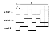
図3は送信信号及び受信信号の排他論理和の出力レベルを示す図である。光コネクタCが光ポートPと正常に接続している場合における、コンパレータ23b-1の出力である送信信号Tx1と、コンパレータ23b-2の出力である受信信号Rx1と、XOR23cの出力であるXOR信号とを示している。
光コネクタCが光ポートPと正常に接続していれば、光ポートPにおける受信光は、対向装置から送信された信号光となる。そのため、受信光をO/E変換した受信信号Rxの符号と、光伝送装置20が送信する送信信号Txの符号とは、一定時間の間、それぞれ符号の値は異なり、同一の符号とはならない(光伝送装置10が送信するデータと、対向装置から送信されたデータは異なるということ)。したがって、一定時間Tの間、送信信号Tx1と受信信号Rx1との排他論理和をとれば、レベル変化が生じている信号が得られることになる。
図3の場合、送信信号Tx1の符号と、受信信号Rx1との符号とは、一定時間Tにおいて、同一符号ではなく互いに異なる値となる。そして、時間t毎に、送信信号Tx1と受信信号Rx1との排他論理和をとると(時間tの幅で同符号ならLレベル、異符号ならHレベル)、XOR信号の出力レベルは、一定時間Tにおいて、レベル変化が生じる信号となる。
図2の説明に戻って、光レベル制御部23dは、XOR信号を受信すると、一定時間Tで、XOR信号にはレベル変化が生じていることを検出し、光コネクタCが光ポートPと正常に接続していることを認識する。したがって、光レベル制御部23dは、光コネクタCが光ポートPと正常に接続している場合の光受信時においては、LD駆動部21aに対する駆動停止制御は行わない。
(光コネクタCと光ポートPとの接続が不完全な場合)
光送信時、上記のようにして、光送信部21から送信光が出力し、送信光は、光方向性結合器24のポートp1からポートp2を通過する。送信光は、光ポートPへ向かって流れるが、光ファイバfが正常に接続されていないため、光ポートPで送信光の反射が生じる。送信光の反射戻り光は、光方向性結合器24のポートp2に入力し、ポートp3から出力される。
光送信時、上記のようにして、光送信部21から送信光が出力し、送信光は、光方向性結合器24のポートp1からポートp2を通過する。送信光は、光ポートPへ向かって流れるが、光ファイバfが正常に接続されていないため、光ポートPで送信光の反射が生じる。送信光の反射戻り光は、光方向性結合器24のポートp2に入力し、ポートp3から出力される。
PD22aは、受信光(反射戻り光)をO/E変換して光電流を生成する。TIA22bは、I/V変換を行って光電流を電圧信号に変換する。受信アンプ22cは、電圧信号を増幅して受信信号Rxを出力する。
一方、遅延部23aは、送信信号Txを所定時間遅延させる。コンパレータ23b-1は、送信信号Txを波形整形した後の送信信号Tx1を出力し、コンパレータ23b-2は、受信信号Rxを波形整形した後の受信信号Rx1を出力する。また、XOR23cは、コンパレータ23b-1、23b-2からの各出力信号の排他論理和をとったXOR信号を出力する。
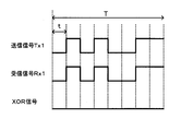
図4は送信信号及び受信信号の排他論理和の出力レベルを示す図である。光コネクタCと光ポートPとの接続が不完全な場合における、コンパレータ23b-1の出力である送信信号Tx1と、コンパレータ23b-2の出力である受信信号Rx1と、XOR23cの出力であるXOR信号とを示している。
光コネクタCと光ポートPとの接続が不完全な場合、光ポートPにおける受信光は、光ポートPで送信光が反射した反射戻り光となる。そのため、反射戻り光をO/E変換した受信信号Rxの符号と、光伝送装置20が送信する送信信号Txの符号とは、同じ信号の符号であるから、一定時間比較すれば同一の符号となる(受信信号Rxは、単に送信信号Txの戻り光をO/E変換した信号であって、本来同じ信号であるから)。したがって、一定時間Tの間、送信信号Tx1と受信信号Rx1との排他論理和をとれば、同一レベルの信号が得られることになる。
図4の場合、送信信号Tx1の符号と、受信信号Rx1との符号とは、一定時間Tにおいて、同一符号となる。そして、時間t毎に、送信信号Tx1と受信信号Rx1との排他論理和をとると(時間tの幅で同符号ならLレベル、異符号ならHレベル)、XOR信号の出力レベルは、一定時間Tにおいて、同一レベル(Lレベル)の信号となる。
図2の説明に戻って、光レベル制御部23dは、XOR信号を受信すると、一定時間Tで、XOR信号はレベル変化のない同一レベルであることを検出することにより、光コネクタCと光ポートPとの接続が不完全であることを認識する。
したがって、光レベル制御部23dは、LD駆動部21aに対して駆動停止制御を実行して、LD21bの光出力を自動停止する。なお、光出力の停止だけでなく、アラームを発して、光コネクタCの接続状態が不完全であることを保守者に通知することもできる。
このように、光伝送装置20では、送信信号Txの符号と、受信信号Rxの符号とを比較し、符号の値が一定時間同じ状態が続く場合は、現在受信している受信光は、光コネクタCの接続不完全により光ポートPで反射した送信光の反射戻り光と認識して、光送信部21の光出力を停止する構成とした。これにより、一芯双方向の光伝送装置20において、光コネクタCの接続不完全時の光出力を自動的に遮断することができ、人体への危険防止を図ることが可能になる。
次に第3の実施の形態の光伝送装置について説明する。図5は光伝送装置の構成例を示す図である。光伝送装置30は、光ポートP、光送信部31、光受信部32、制御部33、光方向性結合器34、低周波信号発生部35を備える。
光送信部31は、LD駆動部31aとLD31bを含み、光受信部32は、PD32a、TIA32b及び受信アンプ32cを含む。また、制御部33は、バンドパスフィルタ33aと光レベル制御部33bを含む。
光ポートPは、光ファイバfとつながる光コネクタCが接続する光ソケットを備えた一芯双方向伝送用の光送受信ポートである。光方向性結合器34は、3ポートを有し、ポートp1から入力した光をポートp2から出力し、ポートp2から入力した光をポートp3から出力する。低周波信号発生部35は、主信号に影響を与えない程度の低周波数の低周波信号3を発生し、LD駆動部31aへ送信する。
光送信部31は、低周波信号3を送信信号Txに重畳してE/O変換し、送信光を生成して光ポートPを介して送信する。光受信部32は、光ポートPを介して受信した受信光をO/E変換して、受信信号Rxを生成する。
制御部33は、光送信部31の光出力レベルを制御する。また、制御部33は、受信信号Rxから低周波信号3の周波数成分を検出した場合は、受信光は光コネクタCの接続不完全により光ポートPで反射した送信光の反射戻り光と認識して、光送信部31の光出力を停止する。
次に動作について説明する。光コネクタCと光ポートPとの接続状態が正常な場合と、接続状態が不完全な場合とに分けて説明する。
(光コネクタCが光ポートPと正常に接続している場合)
光送信時、LD駆動部31aは、制御部33からのLD駆動指示にもとづいて、LD31bを駆動するための信号に送信信号Txを重畳し、さらに低周波信号発生部35で発生した低周波信号3を重畳して、LD駆動信号を生成する。LD31bは、印加されたLD駆動信号により送信光を出力する。
(光コネクタCが光ポートPと正常に接続している場合)
光送信時、LD駆動部31aは、制御部33からのLD駆動指示にもとづいて、LD31bを駆動するための信号に送信信号Txを重畳し、さらに低周波信号発生部35で発生した低周波信号3を重畳して、LD駆動信号を生成する。LD31bは、印加されたLD駆動信号により送信光を出力する。
送信光は、光方向性結合器34のポートp1に入力してポートp2から出力する。そして、光ポートPを介して、光ファイバfを通じて対向装置へ伝送される。
光受信時、光ファイバfを通じて流れてきた対向装置からの信号光は、光ポートPを介して、光伝送装置30に入射する。入射した受信光は、光方向性結合器34のポートp2に入力し、ポートp3から出力される。
光受信時、光ファイバfを通じて流れてきた対向装置からの信号光は、光ポートPを介して、光伝送装置30に入射する。入射した受信光は、光方向性結合器34のポートp2に入力し、ポートp3から出力される。
PD32aは、受信光をO/E変換して光電流を生成する。TIA32bは、I/V変換を行って光電流を電圧信号に変換する。受信アンプ32cは、電圧信号を増幅して受信信号Rxを出力する。
一方、バンドパスフィルタ33aは、受信信号Rxを受信すると、低周波信号3を通過させるフィルタ処理を行う(受信信号Rxの代わりに、TIA32bの出力信号をバンドパスフィルタ33aに入力してもよい)。
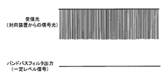
図6はバンドパスフィルタ33aのフィルタ処理を示す図である。光コネクタCが光ポートPと正常に接続している場合における、光ポートPにおける受信光(対向装置から送信された信号光)と、バンドパスフィルタ33aの出力信号とを示している。光コネクタCが光ポートPと正常に接続していれば、光ポートPにおける受信光は、対向装置から送信された信号光となる。
そのため、受信光をO/E変換した受信信号Rxには、低周波信号3は重畳されてはいないので、バンドパスフィルタ33aは、受信信号Rxをフィルタ処理しても低周波信号3を抽出することはなく、一定レベルの信号を出力するだけとなる。
図5の説明に戻って、光レベル制御部33bは、バンドパスフィルタ33aから出力された一定レベル信号を受信すると、光コネクタCが光ポートPと正常に接続していることを認識する。したがって、光レベル制御部33bは、光コネクタCが光ポートPと正常に接続している場合の光受信時においては、LD駆動部31aに対する駆動停止制御は行わない。
(光コネクタCと光ポートPとの接続が不完全な場合)
光送信時、上記のようにして、光送信部31から送信光が出力し、送信光は、光方向性結合器34のポートp1からポートp2を通過する。送信光は、光ポートPへ向かって流れるが、光ファイバfが正常に接続されていないため、光ポートPで送信光の反射が生じる。送信光の反射戻り光は、光方向性結合器34のポートp2に入力し、ポートp3から出力される。
光送信時、上記のようにして、光送信部31から送信光が出力し、送信光は、光方向性結合器34のポートp1からポートp2を通過する。送信光は、光ポートPへ向かって流れるが、光ファイバfが正常に接続されていないため、光ポートPで送信光の反射が生じる。送信光の反射戻り光は、光方向性結合器34のポートp2に入力し、ポートp3から出力される。
PD32aは、受信光をO/E変換して光電流を生成する。TIA32bは、I/V変換を行って光電流を電圧信号に変換する。受信アンプ32cは、電圧信号を増幅して受信信号Rxを出力する。
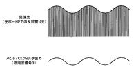
一方、バンドパスフィルタ33aは、受信信号Rxを受信すると低周波信号3を抽出するフィルタ処理を行う。図7はバンドパスフィルタ33aのフィルタ処理を示す図である。光コネクタCと光ポートPとの接続が不完全な場合における、光ポートPにおける受信光(光ポートPで反射した送信光の反射戻り光)と、バンドパスフィルタ33aの出力信号とを示している。光コネクタCと光ポートPとの接続が不完全な場合では、光ポートPにおける受信光は、光ポートPで反射した送信光の反射戻り光となる。
そのため、受信光をO/E変換した受信信号Rxには、低周波信号発生部35で発生した低周波信号3が重畳されているので、バンドパスフィルタ33aは、受信信号Rxのフィルタ処理を行って低周波信号3を抽出して出力することになる。
図5の説明に戻って、光レベル制御部33bは、バンドパスフィルタ33aから出力された低周波信号3を受信すると、光コネクタCと光ポートPとの接続が不完全であることを認識する。
したがって、光レベル制御部33bは、LD駆動部31aに対して駆動停止制御を実行して、LD31bの光出力を自動停止する。なお、光出力の停止だけでなく、アラームを発して、光コネクタCの接続状態が不完全であることを保守者に通知することもできる。
このように、光伝送装置30では、光送信時には低周波信号3を重畳させた送信光を生成し、受信信号Rxから低周波信号3の周波数成分を検出した場合は、現在受信している受信光は、光コネクタCの接続不完全により光ポートPで反射した送信光の反射戻り光と認識して、光送信部31の光出力を停止する構成とした。これにより、一芯双方向の光伝送装置30において、光コネクタCの接続不完全時の光出力を自動的に遮断することができ、人体への危険防止を図ることが可能になる。
上記については単に本発明の原理を示すものである。さらに、多数の変形、変更が当業者にとって可能であり、本発明は上記に示し、説明した正確な構成および応用例に限定されるものではなく、対応するすべての変形例および均等物は、添付の請求項およびその均等物による本発明の範囲とみなされる。
10 光伝送装置
11 光送信器
12 光受信器
13 ハーフミラー
14 反射型波長選択フィルタ(光フィルタ)
15a、15b 波長選択フィルタ
16 制御部
11 光送信器
12 光受信器
13 ハーフミラー
14 反射型波長選択フィルタ(光フィルタ)
15a、15b 波長選択フィルタ
16 制御部
Claims (3)
- 光ファイバとつながる光コネクタが接続する一芯双方向伝送用の光ポートと、
前記光ポートを介して、第1の波長の信号光を送信する光送信器と、
前記光ポートを介して、第2の波長の信号光を受信する光受信器と、
前記光ポートを通じて装置内に入射する光のフィルタリングを行う光フィルタと、
前記光送信器の光出力レベルを制御する制御部と、
を備え、
前記光フィルタは、前記光ポートで反射した前記第1の波長の信号光の反射戻り光を前記制御部へ向けて透過し、前記第2の波長の信号光を前記光受信器へ透過し、
前記制御部は、一定レベルの前記反射戻り光を受信すると、前記光コネクタの接続状態が不完全であると認識して、前記光送信器の光出力を停止する、
ことを特徴とする光伝送装置。 - 光ファイバとつながる光コネクタが接続する一芯双方向伝送用の光ポートと、
送信信号を電気/光変換し、送信光を生成して前記光ポートを介して送信する光送信部と、
前記光ポートを介して受信した受信光を光/電気変換して受信信号を生成する光受信部と、
前記光送信部の光出力レベルを制御する制御部と、
を備え、
前記制御部は、前記送信信号の符号と、前記受信信号の符号とを比較し、符号の値が一定時間同じ状態が続く場合は、前記受信光は前記光コネクタの接続不完全により前記光ポートで反射した前記送信光の反射戻り光であると認識して、前記光送信部の光出力を停止する、
ことを特徴とする光伝送装置。 - 光ファイバとつながる光コネクタが接続する一芯双方向伝送用の光ポートと、
低周波信号を発生する低周波信号発生部と、
前記低周波信号を送信信号に重畳して電気/光変換し、送信光を生成して前記光ポートを介して送信する光送信部と、
前記光ポートを介して受信した受信光を光/電気変換して受信信号を生成する光受信部と、
前記光送信部の光出力レベルを制御する制御部と、
を備え、
前記制御部は、前記受信信号から前記低周波信号を検出した場合は、前記受信光は前記光コネクタの接続不完全により前記光ポートで反射した前記送信光の反射戻り光と認識して、前記光送信部の光出力を停止する、
ことを特徴とする光伝送装置。
Priority Applications (1)
| Application Number | Priority Date | Filing Date | Title |
|---|---|---|---|
| PCT/JP2009/060940 WO2010146659A1 (ja) | 2009-06-16 | 2009-06-16 | 光伝送装置 |
Applications Claiming Priority (1)
| Application Number | Priority Date | Filing Date | Title |
|---|---|---|---|
| PCT/JP2009/060940 WO2010146659A1 (ja) | 2009-06-16 | 2009-06-16 | 光伝送装置 |
Publications (1)
| Publication Number | Publication Date |
|---|---|
| WO2010146659A1 true WO2010146659A1 (ja) | 2010-12-23 |
Family
ID=43355997
Family Applications (1)
| Application Number | Title | Priority Date | Filing Date |
|---|---|---|---|
| PCT/JP2009/060940 Ceased WO2010146659A1 (ja) | 2009-06-16 | 2009-06-16 | 光伝送装置 |
Country Status (1)
| Country | Link |
|---|---|
| WO (1) | WO2010146659A1 (ja) |
Cited By (3)
| Publication number | Priority date | Publication date | Assignee | Title |
|---|---|---|---|---|
| CN102511138A (zh) * | 2011-12-21 | 2012-06-20 | 华为技术有限公司 | 可调光收发器、无源光网络系统及设备 |
| EP2747310A1 (en) * | 2012-12-19 | 2014-06-25 | Alcatel Lucent | Optical data transmission device |
| WO2020246375A1 (ja) * | 2019-06-06 | 2020-12-10 | 京セラ株式会社 | 光ファイバー給電システムの光コネクタ及び給電装置並びに光ファイバー給電システム |
Citations (5)
| Publication number | Priority date | Publication date | Assignee | Title |
|---|---|---|---|---|
| JPH01119232U (ja) * | 1988-02-08 | 1989-08-11 | ||
| JPH0267027A (ja) * | 1988-09-01 | 1990-03-07 | Fujitsu Ltd | 双方向光通信回路 |
| JPH03276781A (ja) * | 1990-03-27 | 1991-12-06 | Nec Corp | レーザ光出力器 |
| JPH04318714A (ja) * | 1991-04-18 | 1992-11-10 | Nec Corp | 光双方向伝送装置 |
| JPH09294109A (ja) * | 1996-03-01 | 1997-11-11 | Fujitsu Ltd | 光増幅双方向伝送装置 |
-
2009
- 2009-06-16 WO PCT/JP2009/060940 patent/WO2010146659A1/ja not_active Ceased
Patent Citations (5)
| Publication number | Priority date | Publication date | Assignee | Title |
|---|---|---|---|---|
| JPH01119232U (ja) * | 1988-02-08 | 1989-08-11 | ||
| JPH0267027A (ja) * | 1988-09-01 | 1990-03-07 | Fujitsu Ltd | 双方向光通信回路 |
| JPH03276781A (ja) * | 1990-03-27 | 1991-12-06 | Nec Corp | レーザ光出力器 |
| JPH04318714A (ja) * | 1991-04-18 | 1992-11-10 | Nec Corp | 光双方向伝送装置 |
| JPH09294109A (ja) * | 1996-03-01 | 1997-11-11 | Fujitsu Ltd | 光増幅双方向伝送装置 |
Cited By (6)
| Publication number | Priority date | Publication date | Assignee | Title |
|---|---|---|---|---|
| CN102511138A (zh) * | 2011-12-21 | 2012-06-20 | 华为技术有限公司 | 可调光收发器、无源光网络系统及设备 |
| WO2013091190A1 (zh) * | 2011-12-21 | 2013-06-27 | 华为技术有限公司 | 可调光收发器、无源光网络系统及设备 |
| CN102511138B (zh) * | 2011-12-21 | 2014-10-08 | 华为技术有限公司 | 可调光收发器、无源光网络系统及设备 |
| EP2747310A1 (en) * | 2012-12-19 | 2014-06-25 | Alcatel Lucent | Optical data transmission device |
| WO2020246375A1 (ja) * | 2019-06-06 | 2020-12-10 | 京セラ株式会社 | 光ファイバー給電システムの光コネクタ及び給電装置並びに光ファイバー給電システム |
| US11509401B2 (en) | 2019-06-06 | 2022-11-22 | Kyocera Corporation | Optical connector and power sourcing equipment of power over fiber system, and power over fiber system |
Similar Documents
| Publication | Publication Date | Title |
|---|---|---|
| US7920787B2 (en) | Method for detecting a check-back signal in an optical transmission system | |
| US20050201761A1 (en) | SINGLE FIBER TRANSCEIVER with FAULT LOCALIZATION | |
| US20160099782A1 (en) | Light receiving device and method, and optical transceiving integrated module | |
| US11137561B2 (en) | Power over fiber system and data communication devices | |
| US9843383B2 (en) | Multifunctional laser diode driving circuit, a module comprising the same, and a method using the same | |
| CN106452568B (zh) | 具有otdr功能的osc光模块及其实现实时、中断业务检测的方法 | |
| US20170142503A1 (en) | Optical transmitter-receiver and loop-back method | |
| CN112311450A (zh) | 一种可集成otdr功能的异波长单纤双向光模块及其检测方法 | |
| CN103051382A (zh) | 光模块以及应用于光模块的光器件 | |
| CN101170360B (zh) | 一种信号光功率检测设备及检测方法 | |
| CN101834660A (zh) | 光模块的控制装置、方法及光发射装置 | |
| JP3209242B2 (ja) | 高出力光送信部の出力シャットダウン制御装置 | |
| KR101530655B1 (ko) | 단일의 바이 패스용 광 스위치를 구비한 광신호 송수신 네트워크 단말장치 및 그를 포함하는 단일 광섬유 라인 광 네트워크 이더넷 시스템 | |
| US11888513B2 (en) | Optronic transceiver module with integrated protection | |
| EP1309109A2 (en) | Apparatus and method for monitoring an optical transmission line | |
| CN101882958B (zh) | Apr保护方法及装置 | |
| US7132646B2 (en) | Signal light interruption detecting method and optical amplifier using same | |
| US20070103766A1 (en) | Method for monitoring an optical transmission line by means of an optical amplifier and optical amplifier therefor | |
| US9166693B2 (en) | Optical transceiver having reset sequence | |
| CN104320196A (zh) | 一种噪声抑制电路、方法、光模块及光通信系统 | |
| CN104677493B (zh) | 一种光功率实时监测装置 | |
| JP2697659B2 (ja) | 光通信システム | |
| CN204439209U (zh) | 光功率实时监测装置 | |
| KR200284994Y1 (ko) | 광인터페이스보드의 광출력제어장치 | |
| JP3824902B2 (ja) | 光中継装置および光伝送端局装置 |
Legal Events
| Date | Code | Title | Description |
|---|---|---|---|
| 121 | Ep: the epo has been informed by wipo that ep was designated in this application |
Ref document number: 09846152 Country of ref document: EP Kind code of ref document: A1 |
|
| NENP | Non-entry into the national phase |
Ref country code: DE |
|
| 122 | Ep: pct application non-entry in european phase |
Ref document number: 09846152 Country of ref document: EP Kind code of ref document: A1 |
|
| NENP | Non-entry into the national phase |
Ref country code: JP |