WO2010146690A1 - Corps de structure de véhicule - Google Patents
Corps de structure de véhicule Download PDFInfo
- Publication number
- WO2010146690A1 WO2010146690A1 PCT/JP2009/061106 JP2009061106W WO2010146690A1 WO 2010146690 A1 WO2010146690 A1 WO 2010146690A1 JP 2009061106 W JP2009061106 W JP 2009061106W WO 2010146690 A1 WO2010146690 A1 WO 2010146690A1
- Authority
- WO
- WIPO (PCT)
- Prior art keywords
- side rail
- roof side
- center pillar
- vehicle
- cross
- Prior art date
- Legal status (The legal status is an assumption and is not a legal conclusion. Google has not performed a legal analysis and makes no representation as to the accuracy of the status listed.)
- Ceased
Links
Images


Classifications
-
- B—PERFORMING OPERATIONS; TRANSPORTING
- B62—LAND VEHICLES FOR TRAVELLING OTHERWISE THAN ON RAILS
- B62D—MOTOR VEHICLES; TRAILERS
- B62D25/00—Superstructure or monocoque structure sub-units; Parts or details thereof not otherwise provided for
- B62D25/06—Fixed roofs
-
- B—PERFORMING OPERATIONS; TRANSPORTING
- B62—LAND VEHICLES FOR TRAVELLING OTHERWISE THAN ON RAILS
- B62D—MOTOR VEHICLES; TRAILERS
- B62D25/00—Superstructure or monocoque structure sub-units; Parts or details thereof not otherwise provided for
- B62D25/04—Door pillars ; windshield pillars
Definitions
- a vehicle structure having a roof side rail and a center pillar as described in, for example, Japanese Patent Application Laid-Open No. 2008-37123, a vehicle width direction end portion and a vehicle side portion of a rear header disposed at a rear end of the roof 2.
- a structure in which a frame that joins a vehicle upper end portion of a center pillar erected in the center and joins the joint portion and an underbody is known. According to this vehicle structure, the torsional rigidity of the upper part of the vehicle body can be improved, and sufficient rigidity of the upper part of the vehicle body can be ensured.
- the present invention has been made to solve such a technical problem, and provides a vehicle structure that can change a desired shape when a load is applied and can suppress deformation of a center pillar. For the purpose.
- a vehicle structure according to the present invention is connected to a roof side rail that extends in the vehicle front-rear direction on both ends in the vehicle width direction, and a rear end portion of the roof side rail, and extends in the vertical direction of the vehicle.
- a center pillar, and the roof side rail has a cross-sectional area that is narrowed from the front of the center pillar toward the rear end of the roof side rail.
- the cross-sectional area of the roof side rail is reduced from the front of the center pillar toward the rear end of the roof side rail, the cross-sectional area is reduced when, for example, a collision load acts on the roof side rail.
- the bent portion can be easily bent and deformed.
- the moment input to the center pillar can be reduced, and the deformation of the center pillar can be suppressed.
- a desired shape change can be made when a load is applied, and deformation of the center pillar can be suppressed.
- the center pillar reinforcement for generating the predetermined load can be minimized.
- the cross-sectional area of the roof side rail is continuously reduced over a predetermined length from the front of the center pillar toward the rear end of the roof side rail. In this way, it is possible to suppress a decrease in structural strength due to a rapid reduction in the cross-sectional area.
- FIG. 1 is a perspective view showing a vehicle having a vehicle structure according to the embodiment
- FIG. 2 is a cross-sectional view taken along II-II in FIG.
- the vehicle structure according to the present embodiment is formed by crushing the cross section of the rear end portion 10a of the roof side rail 10 and joining it to the center pillar reinforcing portion 20a in an upper body made of carbon fiber reinforced plastic (Carbon Fiber Replastics Plastics: CFRP).
- CFRP Carbon Fiber Replastics Plastics
- this vehicle structure is arranged on a roof portion of a vehicle and extends in the vehicle front-rear direction on both ends in the vehicle width direction, and a rear end portion of the roof side rail 10.
- the center pillar 20 is connected to the vehicle 10a and extends in the vehicle vertical direction
- the quarter 30 is disposed behind the roof side rail 10 and extends in the vehicle width direction.
- the roof side rail 10, the center pillar 20, and the quarter 30 are joined by welding or the like.
- the roof side rail 10 has a closed cross-sectional structure including a roof side rail outer 11 disposed outside the vehicle and a roof side rail inner 12 disposed inside the vehicle.
- the roof side rail 10 is formed by welding or the like with the roof side rail outer 11 and the roof side rail inner 12 facing each other.
- the roof side rail 10 has a substantially constant cross-sectional area from the front end to the front position P of the center pillar 20, and the cross-sectional area is narrowed from the front position P toward the rear end of the roof side rail 10. .
- the roof side rail 10 has a substantially constant shape and size from the front end of the roof side rail 10 to the front position P of the center pillar 20.
- the section 10 is formed to be gradually smaller so that the cross section is crushed up to a position S just before the joint portion between the center pillar 20 and the center pillar 20. And the part by which the cross section was crushed forms cross-sectional crushing part 10b. As shown in FIG.
- the cross-sectional crushing portion 10b starts to squeeze the cross-sectional area from the near position P, gradually decreases over the length from the near position P to the immediately preceding position S, and is almost completely crushed at the immediately preceding position S. ing.
- the cross-sectional area from the front end of the roof side rail 10 to the front position P is not limited to being substantially constant, and the height from the front end to the front position P may change in the vehicle longitudinal direction. Then, comparing the part from the front end to the front position P and the part from the front position P to the previous position S by the change in the height in the front-rear direction, the part from the front position P to the previous position S is the unit. It is formed so that the amount of change in height per length becomes larger.
- the quarter 30 has a closed section structure with a quarter outer 31 disposed outside the vehicle and a quarter inner 32 disposed inside the vehicle.
- the quarter 30 is formed by welding or the like with a quarter outer 31 and a quarter inner 32 facing each other.
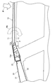
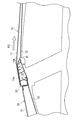
- FIG. 3 and 4 are views for explaining the deformation of the roof side rail when a collision load is applied.
- an arrow F1 indicates the traveling direction of the collision device. From the position P before the center pillar 20 to the position S just before the joint portion between the roof side rail 10 and the center pillar 20 in the initial stage when the collision device advances along the arrow F1 and the collision load acts on the roof side rail 10. Since the cross-sectional area is reduced, the roof side rail 10 is easily broken at the portion where the cross-sectional area is reduced (that is, the cross-sectional crushing portion 10b). Thereby, the input of the moment My to the center pillar 20 can be reduced, and deformation of the center pillar 20 can be suppressed. As a result, a desired shape change can be made when a load is applied, and deformation of the center pillar 20 can be suppressed.
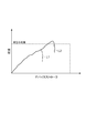
- FIG. 5 is a diagram showing the relationship between device stroke and load.
- the horizontal axis is the device stroke
- the vertical axis is the collision load.
- FIG. 5 by directly supporting the force in the collision device traveling direction with the center pillar 20 in the latter half of the collision, it becomes possible to minimize reinforcement of the center pillar 20 for generating a predetermined load. . Further, by minimizing the reinforcement of the center pillar 20 as described above, it is possible to easily maintain the weight reduction of the vehicle. *
- embodiment mentioned above shows an example of the vehicle structure which concerns on this invention.
- the vehicle structure according to the present invention is not limited to the one described in the above embodiment.
- the vehicle structure according to the present invention may be obtained by modifying the vehicle structure according to the embodiment so as not to change the gist described in each claim, or by applying to another.
Landscapes
- Engineering & Computer Science (AREA)
- Chemical & Material Sciences (AREA)
- Combustion & Propulsion (AREA)
- Transportation (AREA)
- Mechanical Engineering (AREA)
- Body Structure For Vehicles (AREA)
Abstract
Priority Applications (5)
| Application Number | Priority Date | Filing Date | Title |
|---|---|---|---|
| CN200980159936.6A CN102803050B (zh) | 2009-06-18 | 2009-06-18 | 车辆结构体 |
| PCT/JP2009/061106 WO2010146690A1 (fr) | 2009-06-18 | 2009-06-18 | Corps de structure de véhicule |
| US13/258,897 US8690231B2 (en) | 2009-06-18 | 2009-06-18 | Vehicle structure body |
| JP2011519368A JP5196018B2 (ja) | 2009-06-18 | 2009-06-18 | 車両構造体 |
| DE112009004961.3T DE112009004961B4 (de) | 2009-06-18 | 2009-06-18 | Fahrzeugaufbau |
Applications Claiming Priority (1)
| Application Number | Priority Date | Filing Date | Title |
|---|---|---|---|
| PCT/JP2009/061106 WO2010146690A1 (fr) | 2009-06-18 | 2009-06-18 | Corps de structure de véhicule |
Publications (1)
| Publication Number | Publication Date |
|---|---|
| WO2010146690A1 true WO2010146690A1 (fr) | 2010-12-23 |
Family
ID=43356028
Family Applications (1)
| Application Number | Title | Priority Date | Filing Date |
|---|---|---|---|
| PCT/JP2009/061106 Ceased WO2010146690A1 (fr) | 2009-06-18 | 2009-06-18 | Corps de structure de véhicule |
Country Status (5)
| Country | Link |
|---|---|
| US (1) | US8690231B2 (fr) |
| JP (1) | JP5196018B2 (fr) |
| CN (1) | CN102803050B (fr) |
| DE (1) | DE112009004961B4 (fr) |
| WO (1) | WO2010146690A1 (fr) |
Cited By (1)
| Publication number | Priority date | Publication date | Assignee | Title |
|---|---|---|---|---|
| CN107914779A (zh) * | 2016-10-07 | 2018-04-17 | 丰田自动车株式会社 | 车辆车顶结构 |
Families Citing this family (6)
| Publication number | Priority date | Publication date | Assignee | Title |
|---|---|---|---|---|
| JP5196018B2 (ja) * | 2009-06-18 | 2013-05-15 | トヨタ自動車株式会社 | 車両構造体 |
| JP5804190B2 (ja) * | 2012-03-23 | 2015-11-04 | トヨタ自動車株式会社 | 車体構造 |
| DE102015100263B3 (de) * | 2015-01-09 | 2016-03-31 | Audi Ag | Strukturbauteil für eine Karosserie eines Personenkraftwagens |
| US9981692B2 (en) | 2015-06-10 | 2018-05-29 | Ford Global Technologies, Llc | Carbon fiber reinforced polymer assembly |
| JP6869287B2 (ja) * | 2019-06-04 | 2021-05-12 | 本田技研工業株式会社 | 車体上部構造 |
| DE102020123300A1 (de) | 2020-09-07 | 2022-03-10 | Audi Aktiengesellschaft | Karosserietragstruktur |
Citations (2)
| Publication number | Priority date | Publication date | Assignee | Title |
|---|---|---|---|---|
| JP2003212148A (ja) * | 2002-01-22 | 2003-07-30 | Fuji Heavy Ind Ltd | 自動車のセンタピラー上部結合構造 |
| JP2008037123A (ja) * | 2006-08-01 | 2008-02-21 | Toyota Motor Corp | 車体の上部構造 |
Family Cites Families (12)
| Publication number | Priority date | Publication date | Assignee | Title |
|---|---|---|---|---|
| JPS5235608Y2 (fr) | 1972-12-19 | 1977-08-13 | ||
| US5332281A (en) * | 1992-04-30 | 1994-07-26 | Ford Motor Company | Space frame construction |
| US5458393A (en) * | 1993-08-11 | 1995-10-17 | Alumax Extrusions, Inc. | Space frame apparatus and process for the manufacture of same |
| ATE205794T1 (de) * | 1997-10-16 | 2001-10-15 | Cosma Int Inc | Durch innenhochdruck geformtes raumfachwerk und verfahren zu dessen herstellung |
| JPH11291947A (ja) | 1998-04-13 | 1999-10-26 | Nissan Motor Co Ltd | 自動車の車体構造 |
| AU2002352636A1 (en) * | 2001-11-09 | 2003-09-09 | Magna International, Inc | Modular underbody for a motor vehicle |
| US6578909B1 (en) * | 2002-08-16 | 2003-06-17 | Ford Global Technologies, L.L.C. | Vehicle roof structure |
| DE102005011834B4 (de) * | 2005-03-15 | 2008-03-13 | Audi Ag | Seitlicher Dachrahmen für ein Kraftfahrzeug |
| US7357448B2 (en) * | 2005-06-06 | 2008-04-15 | Ford Global Technologies, Llc | Unitary hydroformed roof support pillar |
| US7407222B2 (en) * | 2006-02-27 | 2008-08-05 | Nissan Technical Center North America, Inc. | Vehicle body structure |
| JP5041064B2 (ja) * | 2008-12-01 | 2012-10-03 | トヨタ自動車株式会社 | 車両側部構造 |
| JP5196018B2 (ja) * | 2009-06-18 | 2013-05-15 | トヨタ自動車株式会社 | 車両構造体 |
-
2009
- 2009-06-18 JP JP2011519368A patent/JP5196018B2/ja not_active Expired - Fee Related
- 2009-06-18 US US13/258,897 patent/US8690231B2/en active Active
- 2009-06-18 CN CN200980159936.6A patent/CN102803050B/zh not_active Expired - Fee Related
- 2009-06-18 DE DE112009004961.3T patent/DE112009004961B4/de not_active Expired - Fee Related
- 2009-06-18 WO PCT/JP2009/061106 patent/WO2010146690A1/fr not_active Ceased
Patent Citations (2)
| Publication number | Priority date | Publication date | Assignee | Title |
|---|---|---|---|---|
| JP2003212148A (ja) * | 2002-01-22 | 2003-07-30 | Fuji Heavy Ind Ltd | 自動車のセンタピラー上部結合構造 |
| JP2008037123A (ja) * | 2006-08-01 | 2008-02-21 | Toyota Motor Corp | 車体の上部構造 |
Cited By (4)
| Publication number | Priority date | Publication date | Assignee | Title |
|---|---|---|---|---|
| CN107914779A (zh) * | 2016-10-07 | 2018-04-17 | 丰田自动车株式会社 | 车辆车顶结构 |
| EP3305629A3 (fr) * | 2016-10-07 | 2018-07-25 | Toyota Jidosha Kabushiki Kaisha | Structure de toit de véhicule |
| US10370036B2 (en) | 2016-10-07 | 2019-08-06 | Toyota Jidosha Kabushiki Kaisha | Vehicle roof structure |
| CN107914779B (zh) * | 2016-10-07 | 2020-06-02 | 丰田自动车株式会社 | 车辆车顶结构 |
Also Published As
| Publication number | Publication date |
|---|---|
| DE112009004961B4 (de) | 2016-01-21 |
| US8690231B2 (en) | 2014-04-08 |
| CN102803050B (zh) | 2015-04-22 |
| US20120242112A1 (en) | 2012-09-27 |
| DE112009004961T5 (de) | 2012-06-21 |
| JPWO2010146690A1 (ja) | 2012-11-29 |
| JP5196018B2 (ja) | 2013-05-15 |
| CN102803050A (zh) | 2012-11-28 |
Similar Documents
| Publication | Publication Date | Title |
|---|---|---|
| JP5196018B2 (ja) | 車両構造体 | |
| US9004576B2 (en) | Vehicle front structure | |
| JP5927187B2 (ja) | 自動車の中柱補強体 | |
| JP6235628B2 (ja) | 自動車の車体構造 | |
| US8720985B2 (en) | Side body structure for vehicle | |
| US10112651B2 (en) | Vehicle body front structure | |
| JP2009234495A (ja) | 自動車のフレーム構造 | |
| JP6536526B2 (ja) | 車両用ルーフ構造 | |
| KR101765637B1 (ko) | Cfrp를 이용한 차체구조 | |
| JPWO2012121142A1 (ja) | 車体後部構造 | |
| WO2011121919A1 (fr) | Structure d'accouplement entre un montant avant et un longeron latéral d'un véhicule automobile | |
| JP6225653B2 (ja) | 車両の下部車体構造 | |
| JP2016120839A (ja) | 車体前部構造 | |
| US9108684B2 (en) | Rocker end portion structure | |
| CN102514625A (zh) | 一种汽车前纵梁 | |
| JP4534991B2 (ja) | 車体前部構造 | |
| US10696252B2 (en) | Vehicle body structure | |
| JP2010234955A (ja) | 車体後部構造 | |
| JP2007237944A (ja) | 複合構造材 | |
| JP5002550B2 (ja) | 車体前部構造 | |
| JP2015123886A (ja) | バンパリインフォースメント及び車体前部構造 | |
| JP2016107804A (ja) | 車体フレームの補強構造 | |
| JP2016068729A (ja) | 車体上部構造 | |
| JP4747190B2 (ja) | 車体前部構造 | |
| JP2012201300A (ja) | 自動車の前部車体構造 |
Legal Events
| Date | Code | Title | Description |
|---|---|---|---|
| WWE | Wipo information: entry into national phase |
Ref document number: 200980159936.6 Country of ref document: CN |
|
| 121 | Ep: the epo has been informed by wipo that ep was designated in this application |
Ref document number: 09846183 Country of ref document: EP Kind code of ref document: A1 |
|
| DPE1 | Request for preliminary examination filed after expiration of 19th month from priority date (pct application filed from 20040101) | ||
| WWE | Wipo information: entry into national phase |
Ref document number: 13258897 Country of ref document: US |
|
| ENP | Entry into the national phase |
Ref document number: 2011519368 Country of ref document: JP Kind code of ref document: A |
|
| WWE | Wipo information: entry into national phase |
Ref document number: 112009004961 Country of ref document: DE Ref document number: 1120090049613 Country of ref document: DE |
|
| 122 | Ep: pct application non-entry in european phase |
Ref document number: 09846183 Country of ref document: EP Kind code of ref document: A1 |