WO2010146822A1 - クラッチアクチュエータおよびこれを備えるクラッチ - Google Patents
クラッチアクチュエータおよびこれを備えるクラッチ Download PDFInfo
- Publication number
- WO2010146822A1 WO2010146822A1 PCT/JP2010/003926 JP2010003926W WO2010146822A1 WO 2010146822 A1 WO2010146822 A1 WO 2010146822A1 JP 2010003926 W JP2010003926 W JP 2010003926W WO 2010146822 A1 WO2010146822 A1 WO 2010146822A1
- Authority
- WO
- WIPO (PCT)
- Prior art keywords
- clutch actuator
- clutch
- piston
- peripheral surface
- shaft
- Prior art date
- Legal status (The legal status is an assumption and is not a legal conclusion. Google has not performed a legal analysis and makes no representation as to the accuracy of the status listed.)
- Ceased
Links
Images


Classifications
-
- F—MECHANICAL ENGINEERING; LIGHTING; HEATING; WEAPONS; BLASTING
- F16—ENGINEERING ELEMENTS AND UNITS; GENERAL MEASURES FOR PRODUCING AND MAINTAINING EFFECTIVE FUNCTIONING OF MACHINES OR INSTALLATIONS; THERMAL INSULATION IN GENERAL
- F16D—COUPLINGS FOR TRANSMITTING ROTATION; CLUTCHES; BRAKES
- F16D25/00—Fluid-actuated clutches
- F16D25/08—Fluid-actuated clutches with fluid-actuated member not rotating with a clutching member
- F16D25/082—Fluid-actuated clutches with fluid-actuated member not rotating with a clutching member the line of action of the fluid-actuated members co-inciding with the axis of rotation
- F16D25/083—Actuators therefor
-
- F—MECHANICAL ENGINEERING; LIGHTING; HEATING; WEAPONS; BLASTING
- F16—ENGINEERING ELEMENTS AND UNITS; GENERAL MEASURES FOR PRODUCING AND MAINTAINING EFFECTIVE FUNCTIONING OF MACHINES OR INSTALLATIONS; THERMAL INSULATION IN GENERAL
- F16D—COUPLINGS FOR TRANSMITTING ROTATION; CLUTCHES; BRAKES
- F16D25/00—Fluid-actuated clutches
- F16D25/08—Fluid-actuated clutches with fluid-actuated member not rotating with a clutching member
-
- B—PERFORMING OPERATIONS; TRANSPORTING
- B60—VEHICLES IN GENERAL
- B60K—ARRANGEMENT OR MOUNTING OF PROPULSION UNITS OR OF TRANSMISSIONS IN VEHICLES; ARRANGEMENT OR MOUNTING OF PLURAL DIVERSE PRIME-MOVERS IN VEHICLES; AUXILIARY DRIVES FOR VEHICLES; INSTRUMENTATION OR DASHBOARDS FOR VEHICLES; ARRANGEMENTS IN CONNECTION WITH COOLING, AIR INTAKE, GAS EXHAUST OR FUEL SUPPLY OF PROPULSION UNITS IN VEHICLES
- B60K23/00—Arrangement or mounting of control devices for vehicle transmissions, or parts thereof, not otherwise provided for
- B60K23/02—Arrangement or mounting of control devices for vehicle transmissions, or parts thereof, not otherwise provided for for main transmission clutches
-
- F—MECHANICAL ENGINEERING; LIGHTING; HEATING; WEAPONS; BLASTING
- F16—ENGINEERING ELEMENTS AND UNITS; GENERAL MEASURES FOR PRODUCING AND MAINTAINING EFFECTIVE FUNCTIONING OF MACHINES OR INSTALLATIONS; THERMAL INSULATION IN GENERAL
- F16D—COUPLINGS FOR TRANSMITTING ROTATION; CLUTCHES; BRAKES
- F16D28/00—Electrically-actuated clutches
Definitions
- the present invention relates to a technical field of a clutch actuator that controls connection and disconnection of a clutch, and a clutch including the clutch actuator.
- a clutch actuator is used in such a clutch in order to control connection or disconnection between an output shaft on the engine side and an input shaft on the transmission side.
- a flywheel is attached to an output shaft on the engine side so as to be integrally rotatable by a biasing force of a biasing means such as a diaphragm spring by a friction material attached to the input shaft on the transmission side.
- the output shaft on the engine side and the input shaft on the transmission side are connected to each other, and the urging force of the urging means is reduced or removed by the fluid pressure, so that the output shaft on the engine side and the input on the transmission side are connected.
- a clutch actuator for releasing the connection with the shaft is known from German Patent Publication DE 103 23 953 A1.
- FIG. 5 is a partial cross-sectional view in the axial direction of the clutch actuator described in DE10323953A1.
- the clutch actuator a is slidable in the axial direction between a housing d comprising an inner tube b and a case c, and an outer peripheral surface of the inner tube b and an inner peripheral surface of the cylindrical portion of the case c.
- it has a piston g that is fluid-tightly fitted with a seal member e and defines a fluid working chamber f between the housing d and a release bearing h that is attached to the piston g so as to be integrally movable.
- the clutch actuator a is in the state shown in FIG. 5 when no fluid pressure is introduced into the fluid working chamber f, and the piston g is in the right limit position where it enters the housing d most. In this state, the release bearing h does not strongly press the diaphragm spring (not shown) to the left, so that the friction material (not shown) is pressed against the flywheel (not shown) by the urging force of the diaphragm spring, and the clutch a is in the connected state.
- the foreign matter intrusion prevention means i includes a cylindrical cover j that covers the outer peripheral surface of the cylindrical portion of the case c, and an inner peripheral surface of the cover j attached to the inner peripheral surface of the cover j and the outer peripheral surface of the cylindrical portion of the case c. And a sealing member k for sealing The cover j is attached to the piston g, and the cover j and the seal member k move integrally with the piston g as the piston g moves.
- the dedicated cover j is used as the foreign matter intrusion prevention means i, so that there is a problem that not only the structure is complicated but the number of parts is increased and the cost is high.
- the inner tube b and the case c are formed separately and are joined to each other by welding or the like. For this reason, there is a problem that not only a highly accurate housing cannot be obtained, but also the processing becomes complicated.
- the release bearing h is fixed to the piston g with a hook-shaped specially shaped stopper m. For this reason, it is necessary to form the stopper m of this special shape on the piston g, and not only the shape of the piston g is complicated, but also there is a problem that the release bearing h is attached to and detached from the piston g.
- An object of the present invention is to provide a highly accurate and inexpensive clutch actuator capable of simplifying the structure to reduce the number of parts and easily attaching / detaching the release bearing, and a clutch provided with the same.
- the clutch actuator according to the present invention is fluid-tight and slidable between a housing having an inner cylinder and an outer cylinder, and an outer peripheral surface of the inner cylinder and an inner peripheral surface of the outer cylinder. And a piston that is actuated by the fluid pressure of the working fluid introduced into the fluid working chamber, and is disposed on the piston so as to be movable together with the piston and a clutch.
- the housing is formed by integrally forming the inner cylinder and the outer cylinder as a single member, and between the inner peripheral surface of the outer cylinder and the piston.
- Foreign matter intrusion prevention means for preventing foreign matter from entering the fluid working chamber through the outer cylinder is provided in the outer cylinder.
- the clutch actuator according to the present invention is characterized in that the foreign matter intrusion preventing means is a seal member disposed on the inner peripheral surface side of the outer cylinder.
- the clutch actuator of the present invention is characterized in that the release bearing is detachably attached to the piston by a snap ring.
- the clutch of the present invention includes a first shaft to which an output of the driving device is transmitted, a driving side rotating member attached to the first shaft so as to be integrally rotatable with the first shaft, and the driving device.
- foreign matter intrusion prevention means for preventing foreign matter from entering the fluid working chamber through the space between the inner peripheral surface of the outer tube and the piston is arranged on the outer tube.
- a dedicated cover such as the clutch actuator described in DE 10323953A1 can be eliminated.
- the number of parts of the clutch actuator can be reduced and the structure of the clutch actuator can be simplified, and the cost can be reduced accordingly.
- the structure of the clutch actuator can be simplified more effectively by using a seal member disposed on the inner peripheral surface side of the outer cylinder as the foreign matter intrusion prevention means.
- the inner cylinder and the outer cylinder are formed by integral molding of a single member, a highly accurate housing can be obtained and processing can be simplified.
- the release bearing is detachably attached to the piston with a simple-shaped snap ring. Therefore, the release bearing can be easily attached to and detached from the piston, and the piston can be made in a simpler shape.
- FIG. 1 is a diagram schematically showing an example of a clutch provided with an example of an embodiment of a clutch actuator according to the present invention.
- the clutch 1 of this example rotates integrally with the output shaft 2 on an output shaft 2 (corresponding to the first shaft of the present invention) to which the output of the engine (driving device of the present invention) is transmitted.
- a flywheel 3 (corresponding to the driving side rotating member of the present invention) connected in a possible manner, and a transmission side input shaft 4 (corresponding to the second shaft of the present invention) which is a driven device driven by the output of the engine
- a friction material 6 (corresponding to the driven side rotation member of the present invention) connected to the input shaft 4 through a disc-like support member 5 so as to rotate integrally therewith, and a friction material pressing for pressing the friction material 6 against the flywheel 3
- a member 7, a diaphragm spring 8 that is a biasing means for biasing the friction material pressing member 7 so that the friction material pressing member 7 presses the friction material 6, and a clutch actuator 9 that controls the diaphragm spring 8 are provided. Yes.
- the output shaft 2, the flywheel 3, and the input shaft 4 are rota
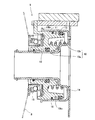
- FIG. 2 is a cross-sectional view along the axial direction showing the clutch actuator during non-operation of this example
- FIG. 3 is a cross-sectional view along the axial direction showing the clutch actuator during operation of this example.
- the clutch actuator 9 of this example has a single case 10b having an inner tube 10a (corresponding to the inner cylinder of the present invention) and a cylindrical portion 10b 1 (corresponding to the outer cylinder of the present invention). It has a housing 10 that is integrally formed with members. In that case, the inner tube 10a and the cylindrical portion 10b 1 is disposed coaxially. Also, as with the clutch actuator according to DE10323953A1, the piston 11 is slidably disposed between the outer circumference and the cylindrical portion 10b inner peripheral surface of the first case 10b of the inner tube 10a.
- the piston 11 is fluid-tightly fitted to the outer peripheral surface of the inner tube 10a by an annular seal member 12, and is guided by the inner tube 10a to the inner tube 10a in the axial direction (left-right direction in FIG. 2). It is possible to move to. Further, the piston 11 is fitted fluid-tightly by the annular seal member 13 on the inner peripheral surface of the cylindrical portion 10b 1 of the case 10b. Thereby, a fluid working chamber 14 is defined between the piston 11 and the housing 10.
- the piston 11 is provided with a release bearing 15.
- the release bearing 15 is detachably attached to the piston 11 by a snap ring 16.
- the release bearing 15 strongly presses the diaphragm spring 8 leftward by the movement of the piston 11 leftward in FIG.
- the piston 11 is constantly urged in a direction in which the release bearing 15 presses the diaphragm spring 8 by a coil spring 17 that is urging means.
- the urging force that presses the release bearing 15 and the piston 11 to the right by the diaphragm spring 8 is the piston 11 and the release bearing 15 by the coil spring 17. It is set to be larger than the urging force that pushes leftward. Accordingly, when the clutch actuator 9 shown in FIG. 2 is not in operation, in which the fluid pressure is not introduced into the fluid working chamber 14, the piston 11 enters the housing 10 to the right limit position.
- annular seal member 18 is disposed on the inner peripheral surface of the cylindrical portion 10b 1 of the housing 10.
- the sealing member 18, the sealing member accommodation projecting from the outer peripheral surface of the cylindrical portion 10b 1 as the inner peripheral surface of the provided and the tubular portion 10b 1 is recessed in the axial end of the cylindrical portion 10b 1 It is disposed in the part 19.
- the seal member accommodating portion 19, that is, the seal member 18 is disposed on the opening end side of the tubular portion 10 b 1 from the seal member 13.
- the seal member 18 is configured so that foreign matters such as dust existing on the outer peripheral side of the housing 10 pass between the inner peripheral surface of the cylindrical portion 10 b 1 of the housing 10 and the outer peripheral surface of the piston 11 toward the fluid working chamber 14. Prevent intrusion.
- the clutch actuator 9 and the clutch 1 of this example as a foreign substance intrusion prevention means, uses only seal member 18 disposed on the inner peripheral surface of the cylindrical portion 10b 1 of the case 10b. Therefore, a dedicated cover such as the clutch actuator described in DE 10323953A1 can be eliminated. As a result, the number of parts of the clutch actuator 9 can be reduced and the structure of the clutch actuator 9 can be simplified, and the cost can be reduced accordingly. In particular, the structure of the clutch actuator 9 can be simplified more effectively by using the seal member 18 as a foreign matter intrusion prevention means.
- the release bearing 15 is detachably attached to the piston 11 with a snap ring 16 having a simple shape. Accordingly, the release bearing 15 can be easily attached to and detached from the piston 11, and the piston 11 can be made into a simpler shape.
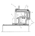
- FIG. 4 is a cross-sectional view similar to FIG. 2, showing another example of the embodiment of the clutch actuator according to the present invention.
- the sealing member 18 is a piston 11 It is provided on the surface.
- the seal member 18 is disposed on the outer peripheral surface of the piston that slides with the inner peripheral surface of the cylindrical portion 10b 1 even when the piston 11 is moved to the maximum.
- the seal member 18 is disposed on the piston 11, so that the seal member accommodating portion 19 of the above-described example provided in the cylindrical portion 10 b 1 can be made unnecessary.
- the shape of the case 10b is simplified, and the processing of the housing 10 is facilitated. Further, in the example shown in FIG.
- the annular flange 10b 2 are provided on the open end of the cylindrical portion 10b 1, the flange 10b 2 may be omitted. In this way, the shape of the case 10b becomes easier, with the processing is further facilitated in the housing 10, since there is no protrusion on the outer peripheral surface of the tubular portion 10b 1, the interference with other members No need to consider it.
- the clutch actuator according to the present invention and the clutch including the clutch actuator can be used for a clutch actuator that controls connection and disconnection of the clutch and a clutch including the clutch actuator, and more particularly to a clutch actuator that operates with fluid pressure and a clutch including the clutch actuator. It can be suitably used.
Landscapes
- Engineering & Computer Science (AREA)
- General Engineering & Computer Science (AREA)
- Mechanical Engineering (AREA)
- Chemical & Material Sciences (AREA)
- Combustion & Propulsion (AREA)
- Transportation (AREA)
- Physics & Mathematics (AREA)
- Electromagnetism (AREA)
- Hydraulic Clutches, Magnetic Clutches, Fluid Clutches, And Fluid Joints (AREA)
- Mechanical Operated Clutches (AREA)
Abstract
Description
図2に示すクラッチアクチュエータ9の非作動状態では、前述のようにピストン11は右限位置にある。このピストン11の状態では、リリースベアリング15がダイヤフラムスプリング8を左方へ強く押圧しない。したがって、前述のようにダイヤフラムスプリング8の付勢力で摩擦材押付部材7が摩擦材6をフライホイール3に押し付けている。これにより、クラッチ1は接続状態にある。
Claims (4)
- 内筒と外筒とを有するハウジングと、前記内筒の外周面および前記外筒の内周面とに流体密にかつ摺動可能に嵌合されて流体作動室を区画形成するとともに前記流体作動室に導入される作動流体の流体圧によって作動されるピストンと、前記ピストンにこのピストンと一体移動可能に配設されるとともにクラッチを切断するリリースベアリングとを少なくとも有するクラッチアクチュエータにおいて、
前記ハウジングは前記内筒と前記外筒とが単一部材で一体成形されて形成されており、
前記外筒の内周面と前記ピストンとの間を通して異物が前記流体作動室内に侵入するのを防止する異物侵入防止手段が、前記外筒に配設されていることを特徴とするクラッチアクチュエータ。 - 前記異物侵入防止手段は、前記外筒の内周面側に配設されたシール部材であることを特徴とする請求項1に記載のクラッチアクチュエータ。
- 前記リリースベアリングは前記ピストンに、スナップリングにより着脱可能に取り付けられていることを特徴とする請求項1または2に記載のクラッチアクチュエータ。
- 駆動装置の出力が伝達される第1の軸と、前記第1の軸にこの第1の軸と一体回転可能に取り付けられた駆動側回転部材と、前記駆動装置の出力により駆動される被駆動装置の第2の軸と、前記第2の軸にこの第2の軸と一体回転可能にかつ前記駆動側回転部材に圧接および離間可能に取り付けられた従動側回転部材と、前記従動側回転部材を前記駆動側回転部材に圧接する従動側回転部材押付部材と、前記従動側回転部材押付部材を作動制御するクラッチアクチュエータとを少なくとも備えたクラッチにおいて、
前記クラッチアクチュエータは、請求項1ないし3のいずれか1に記載のクラッチアクチュエータであることを特徴とするクラッチ。
Priority Applications (4)
| Application Number | Priority Date | Filing Date | Title |
|---|---|---|---|
| CN2010800266768A CN102459940A (zh) | 2009-06-15 | 2010-06-14 | 离合器致动器以及具备该离合器致动器的离合器 |
| EP10789204A EP2444683A1 (en) | 2009-06-15 | 2010-06-14 | Clutch actuator and clutch provided with the same |
| KR1020117029795A KR101342426B1 (ko) | 2009-06-15 | 2010-06-14 | 클러치 액추에이터 및 이것을 구비하는 클러치 |
| JP2011519537A JPWO2010146822A1 (ja) | 2009-06-15 | 2010-06-14 | クラッチアクチュエータおよびこれを備えるクラッチ |
Applications Claiming Priority (2)
| Application Number | Priority Date | Filing Date | Title |
|---|---|---|---|
| JP2009141968 | 2009-06-15 | ||
| JP2009-141968 | 2009-06-15 |
Publications (1)
| Publication Number | Publication Date |
|---|---|
| WO2010146822A1 true WO2010146822A1 (ja) | 2010-12-23 |
Family
ID=43356155
Family Applications (1)
| Application Number | Title | Priority Date | Filing Date |
|---|---|---|---|
| PCT/JP2010/003926 Ceased WO2010146822A1 (ja) | 2009-06-15 | 2010-06-14 | クラッチアクチュエータおよびこれを備えるクラッチ |
Country Status (5)
| Country | Link |
|---|---|
| EP (1) | EP2444683A1 (ja) |
| JP (1) | JPWO2010146822A1 (ja) |
| KR (1) | KR101342426B1 (ja) |
| CN (1) | CN102459940A (ja) |
| WO (1) | WO2010146822A1 (ja) |
Cited By (2)
| Publication number | Priority date | Publication date | Assignee | Title |
|---|---|---|---|---|
| CN106640899A (zh) * | 2016-12-28 | 2017-05-10 | 安徽六国化工股份有限公司 | 一种用于气动离合器中的轴向锁紧装置 |
| CN112065876A (zh) * | 2019-06-11 | 2020-12-11 | 斯凯孚公司 | 密封的离合器推力轴承装置以及包括这种装置的传动系统 |
Families Citing this family (7)
| Publication number | Priority date | Publication date | Assignee | Title |
|---|---|---|---|---|
| KR101897303B1 (ko) * | 2013-10-10 | 2018-09-11 | 현대건설기계 주식회사 | 건설장비용 파킹브레이크장치 |
| KR101600918B1 (ko) | 2014-09-23 | 2016-03-08 | 주식회사 인팩 | 클러치 액추에이터 |
| KR101710938B1 (ko) * | 2016-09-22 | 2017-02-28 | (주)에너토크 | 밸브 액추에이터 |
| JP6802120B2 (ja) * | 2017-07-26 | 2020-12-16 | 株式会社エクセディ | クラッチレリーズ装置 |
| US12071017B2 (en) * | 2019-12-27 | 2024-08-27 | Dayco Europe S.R.L. | Transmission module provided with a hydraulic actuator |
| KR102284510B1 (ko) * | 2020-01-31 | 2021-07-30 | 주식회사평화발레오 | 컨센트릭 클러치 액츄에이터 |
| CN115076251A (zh) * | 2022-07-11 | 2022-09-20 | 青岛科麟智传汽车科技有限公司 | 一种商用车集成式离合器驱动装置 |
Citations (5)
| Publication number | Priority date | Publication date | Assignee | Title |
|---|---|---|---|---|
| JPS5360300U (ja) * | 1976-10-22 | 1978-05-23 | ||
| JPH0267123U (ja) * | 1988-11-09 | 1990-05-21 | ||
| JPH04500261A (ja) * | 1988-08-30 | 1992-01-16 | フェデラル―モーギュル・コーポレーション | 液圧作動クラッチ解放機構 |
| JPH10220495A (ja) * | 1997-01-31 | 1998-08-21 | Koyo Seiko Co Ltd | 油圧式クラッチ遮断装置 |
| DE10323953A1 (de) | 2003-05-27 | 2004-12-16 | Zf Sachs Ag | Betätigungseinrichtung für eine Fahrzeugkupplung |
Family Cites Families (5)
| Publication number | Priority date | Publication date | Assignee | Title |
|---|---|---|---|---|
| JPH0134985Y2 (ja) * | 1984-11-20 | 1989-10-25 | ||
| DE4407665B4 (de) * | 1994-03-09 | 2005-09-22 | Zf Sachs Ag | Hydraulisch betätigbares Ausrücksystem |
| JP2000274454A (ja) * | 1999-03-25 | 2000-10-03 | Aisin Seiki Co Ltd | ストロークセンサー付クラッチ操作シリンダー装置 |
| CN101287924A (zh) * | 2005-10-11 | 2008-10-15 | 卢克摩擦片和离合器两合公司 | 具有带轴向间隙的环形活塞的从动缸 |
| JP4724635B2 (ja) * | 2006-10-06 | 2011-07-13 | 株式会社スペシャルパーツ武川 | 二輪車用クラッチ装置 |
-
2010
- 2010-06-14 JP JP2011519537A patent/JPWO2010146822A1/ja active Pending
- 2010-06-14 EP EP10789204A patent/EP2444683A1/en not_active Withdrawn
- 2010-06-14 WO PCT/JP2010/003926 patent/WO2010146822A1/ja not_active Ceased
- 2010-06-14 KR KR1020117029795A patent/KR101342426B1/ko active Active
- 2010-06-14 CN CN2010800266768A patent/CN102459940A/zh active Pending
Patent Citations (5)
| Publication number | Priority date | Publication date | Assignee | Title |
|---|---|---|---|---|
| JPS5360300U (ja) * | 1976-10-22 | 1978-05-23 | ||
| JPH04500261A (ja) * | 1988-08-30 | 1992-01-16 | フェデラル―モーギュル・コーポレーション | 液圧作動クラッチ解放機構 |
| JPH0267123U (ja) * | 1988-11-09 | 1990-05-21 | ||
| JPH10220495A (ja) * | 1997-01-31 | 1998-08-21 | Koyo Seiko Co Ltd | 油圧式クラッチ遮断装置 |
| DE10323953A1 (de) | 2003-05-27 | 2004-12-16 | Zf Sachs Ag | Betätigungseinrichtung für eine Fahrzeugkupplung |
Cited By (3)
| Publication number | Priority date | Publication date | Assignee | Title |
|---|---|---|---|---|
| CN106640899A (zh) * | 2016-12-28 | 2017-05-10 | 安徽六国化工股份有限公司 | 一种用于气动离合器中的轴向锁紧装置 |
| CN112065876A (zh) * | 2019-06-11 | 2020-12-11 | 斯凯孚公司 | 密封的离合器推力轴承装置以及包括这种装置的传动系统 |
| CN112065876B (zh) * | 2019-06-11 | 2025-08-05 | 斯凯孚公司 | 密封的离合器推力轴承装置以及包括这种装置的传动系统 |
Also Published As
| Publication number | Publication date |
|---|---|
| CN102459940A (zh) | 2012-05-16 |
| JPWO2010146822A1 (ja) | 2012-11-29 |
| EP2444683A1 (en) | 2012-04-25 |
| KR101342426B1 (ko) | 2013-12-18 |
| KR20120034653A (ko) | 2012-04-12 |
Similar Documents
| Publication | Publication Date | Title |
|---|---|---|
| JPWO2010146822A1 (ja) | クラッチアクチュエータおよびこれを備えるクラッチ | |
| KR101524327B1 (ko) | 슬레이브 실린더와 릴리즈 시스템 | |
| JP6802120B2 (ja) | クラッチレリーズ装置 | |
| JP2013535628A (ja) | デュアルクラッチ用のレリーズユニット | |
| JP2008281090A (ja) | シール一体型アルミピストン | |
| JP4975723B2 (ja) | モータサイクル用クラッチ装置 | |
| JP2016001033A (ja) | 湿式多板クラッチ装置 | |
| JP7645065B2 (ja) | 密封装置 | |
| US8590686B2 (en) | Pull-type friction clutch with integrated clutch release device | |
| JP5262534B2 (ja) | 油圧式クラッチレリーズ装置 | |
| JP4333469B2 (ja) | 自動変速機のクラッチ装置 | |
| US6814196B2 (en) | Friction clutch with separately controllable transmission brake | |
| JP4364170B2 (ja) | 動力伝達装置 | |
| JP4140594B2 (ja) | 油圧式クラッチレリーズ装置 | |
| JP7402611B2 (ja) | 密封装置 | |
| EP4098901A1 (en) | Concentric clutch actuator | |
| KR102487177B1 (ko) | 자동변속기용 엔드 브레이크 장치 | |
| JP2010101378A (ja) | クラッチ断続装置 | |
| KR101600918B1 (ko) | 클러치 액추에이터 | |
| JP2008121714A (ja) | クラッチ用アクチュエータ | |
| GB1563746A (en) | Wet type clutch | |
| CN114981555B (zh) | 设有液压致动器的传动模块 | |
| WO2005090812A1 (ja) | 油圧式クラッチレリーズ装置 | |
| CN119343542A (zh) | 用于将传动系的驱动侧可逆地联接至输出侧的离合器单元及用于这种类型的离合器单元的致动器 | |
| JP2021124147A (ja) | クラッチレリーズ装置 |
Legal Events
| Date | Code | Title | Description |
|---|---|---|---|
| WWE | Wipo information: entry into national phase |
Ref document number: 201080026676.8 Country of ref document: CN |
|
| 121 | Ep: the epo has been informed by wipo that ep was designated in this application |
Ref document number: 10789204 Country of ref document: EP Kind code of ref document: A1 |
|
| ENP | Entry into the national phase |
Ref document number: 2011519537 Country of ref document: JP Kind code of ref document: A |
|
| REEP | Request for entry into the european phase |
Ref document number: 2010789204 Country of ref document: EP |
|
| WWE | Wipo information: entry into national phase |
Ref document number: 2010789204 Country of ref document: EP |
|
| ENP | Entry into the national phase |
Ref document number: 20117029795 Country of ref document: KR Kind code of ref document: A |
|
| NENP | Non-entry into the national phase |
Ref country code: DE |