WO2010146851A1 - Caméra de télévision et système de commande de caméra de télévision - Google Patents
Caméra de télévision et système de commande de caméra de télévision Download PDFInfo
- Publication number
- WO2010146851A1 WO2010146851A1 PCT/JP2010/004003 JP2010004003W WO2010146851A1 WO 2010146851 A1 WO2010146851 A1 WO 2010146851A1 JP 2010004003 W JP2010004003 W JP 2010004003W WO 2010146851 A1 WO2010146851 A1 WO 2010146851A1
- Authority
- WO
- WIPO (PCT)
- Prior art keywords
- level
- signal
- camera device
- video signal
- television camera
- Prior art date
- Legal status (The legal status is an assumption and is not a legal conclusion. Google has not performed a legal analysis and makes no representation as to the accuracy of the status listed.)
- Ceased
Links
Images









Classifications
-
- H—ELECTRICITY
- H04—ELECTRIC COMMUNICATION TECHNIQUE
- H04N—PICTORIAL COMMUNICATION, e.g. TELEVISION
- H04N17/00—Diagnosis, testing or measuring for television systems or their details
- H04N17/002—Diagnosis, testing or measuring for television systems or their details for television cameras
-
- H—ELECTRICITY
- H04—ELECTRIC COMMUNICATION TECHNIQUE
- H04N—PICTORIAL COMMUNICATION, e.g. TELEVISION
- H04N23/00—Cameras or camera modules comprising electronic image sensors; Control thereof
- H04N23/60—Control of cameras or camera modules
-
- H—ELECTRICITY
- H04—ELECTRIC COMMUNICATION TECHNIQUE
- H04N—PICTORIAL COMMUNICATION, e.g. TELEVISION
- H04N23/00—Cameras or camera modules comprising electronic image sensors; Control thereof
- H04N23/60—Control of cameras or camera modules
- H04N23/63—Control of cameras or camera modules by using electronic viewfinders
- H04N23/633—Control of cameras or camera modules by using electronic viewfinders for displaying additional information relating to control or operation of the camera
- H04N23/634—Warning indications
-
- H—ELECTRICITY
- H04—ELECTRIC COMMUNICATION TECHNIQUE
- H04N—PICTORIAL COMMUNICATION, e.g. TELEVISION
- H04N23/00—Cameras or camera modules comprising electronic image sensors; Control thereof
- H04N23/60—Control of cameras or camera modules
- H04N23/66—Remote control of cameras or camera parts, e.g. by remote control devices
- H04N23/661—Transmitting camera control signals through networks, e.g. control via the Internet
- H04N23/662—Transmitting camera control signals through networks, e.g. control via the Internet by using camera arrangements where one camera controls another camera to affect the control of camera image capture, e.g. placing the camera in a desirable condition to capture a desired image
Definitions
- the present invention relates to a method for adjusting a color signal between television camera devices.
- TV camera devices In a studio site such as a broadcasting station, a plurality of television camera devices (hereinafter referred to as TV camera devices in this document) are simultaneously operated to produce one broadcast program.
- TV camera devices it is an important matter that there is no color shift between the TV camera devices. For example, if there is a color misalignment between the TV camera device A and the TV camera device B, the video acquired by the TV camera device A is switched to the video acquired by the TV camera device B. This is because the color of the video changes, giving the viewer a sense of discomfort.
- a reference chart (gray scale chart, color chart, etc.) is displayed on a plurality of TVs when a plurality of TV camera devices are operated at a broadcast program production site. Take pictures simultaneously with the camera device. Then, while photographing simultaneously, adjustment work is performed so that the video levels of the R (red), G (green), and B (blue) channels are the same among the TV camera devices.
- this adjustment method has the following drawbacks (1) and (2). (1) Since one TV camera device is manually adjusted, the adjustment work takes time as the number of TV camera devices to be operated increases. (2) Because it is an important work to determine the “picture” of the broadcast program to be produced, only those who are familiar with making a picture of the broadcast program can do the work.
- Patent Document 1 discloses a technique of a centralized control device for a TV camera device.
- control device of Patent Document 1 no consideration is given to the setting, management, adjustment, reuse, and the like of various setting values (control parameters) of these TV camera devices. It has not been solved that the setting operation for each camera becomes complicated as the number increases.
- An object of the present invention is to perform color signal adjustment work between TV camera devices easily and at high speed without depending on the skill level of an operator.
- a television camera device of the present invention is a television camera device that spectrally divides a subject image incident through a lens unit and irradiates a solid-state image sensor to convert it into a video signal.
- a video signal obtained by multiplexing signals of red, green, and blue channels whose color signals have been adjusted is input from a television camera device that is a reference for signal adjustment, so that the value of the input video signal is matched.
- the color signal is adjusted.
- the television camera device simultaneously shoots a reference chart taken for the color signal adjustment by the television camera device serving as a reference for the color signal adjustment and matches the value of the input video signal.
- the color signal is adjusted.
- the reference chart is provided with a plurality of predetermined areas, and a television camera device serving as a reference for the color signal adjustment by adjusting the shooting one of the areas to match the position of the predetermined marker.
- the color signal is adjusted after the angle of view is adjusted so as to match the angle of view.
- the television camera device is a video signal obtained by multiplexing the color signal adjusted red, green, and blue channel signals from the television camera device serving as a reference for the color signal adjustment. It is input as a signal in HD-SDI (High Definition TeleVision-Serial Digital Interface) format.
- HD-SDI High Definition TeleVision-Serial Digital Interface
- the television camera apparatus control system of the present invention captures a reference chart, adjusts it to a predetermined angle of view, sets a black level, a white level (gain level), a flare level, a gamma ( ⁇ ) level, And the first television camera device that adjusts the color difference matrix, the transmission line, and the reference chart at the same time as the first television camera device are adjusted and adjusted to the predetermined angle of view.
- the video signal input to the second television camera device via the transmission line is It is a return signal of the camera control apparatus of a 1st television camera apparatus.
- the transmission line is an HD-SDI (High Definition TeleVision-Serial Digital Interface) format signal.
- the television camera device control system of the present invention which is different from the television camera device control system of the above invention, shoots a reference chart, adjusts it to a predetermined angle of view, black level, white level, flare
- the first television camera device for adjusting the level, gamma level, knee, and color difference matrix, the transmission line, and the reference chart are photographed simultaneously with the first television camera device, and the predetermined angle of view is obtained.
- adjusting the video level of the video signal input from the first television camera device via the transmission line and the video signal of the own device so as to match the input video signal.
- Black level, white level, flare level, gamma level, knee, and second television camera apparatus for adjusting color difference matrix It is made of.
- the video signal input to the second television camera device via the transmission line is It is a return signal of the camera control apparatus of a 1st television camera apparatus.
- the transmission line is an HD-SDI (High Definition TeleVision-Serial Digital Interface) format signal.
- the color matching time between TV camera devices can be greatly shortened.
- the degree of variation in color signal adjustment among TV camera devices due to automation of adjustment is reduced.
- the color signal adjustment between the TV camera devices can be performed easily and at high speed without depending on the skill level of the operator.
- the present invention relates to a serial digital signal (hereinafter referred to as an SDI (Serial Digital Interface) signal) of a TV camera device (master) serving as a reference for color signal adjustment to another camera (hereinafter referred to as SDI (Serial Digital Interface) signal).
- SDI Serial Digital Interface
- it is directly input to the slave) and the video level of each channel of the slave is automatically adjusted so that the video level of the video signal of each channel of the master matches the video level of the video signal of each channel of the slave.
- CCU Camera Control Unit
- RET signal the master color signal adjustment reference signal is input and the video level of each channel of the slave is automatically adjusted so that the video level of each channel of the master matches that of the slave.
- FIG. 1 is a block diagram showing a configuration of an embodiment of a TV camera device control system when performing color signal adjustment work of the present invention.
- Reference numeral 100 denotes a studio
- 120 denotes an adjustment room.
- reference numeral 101 denotes a gray scale chart which is one of reference charts (standard subjects)
- reference numerals 102 to 103 denote TV camera devices.
- Reference numeral 102 denotes a master
- 103 and 104 denote slaves.
- the CCU 108 is a master CCU coupled to the master 102 (hereinafter referred to as “MCCU”)
- 111 is a transmission line coupling the MCCU 108 and the CCU 109
- 112 is the MCU 108.
- 105 is a transmission line that couples the master 102 and the MCCU 108
- 106 is a transmission line that couples the slave 103 and the CCU 109
- 107 is a transmission line that couples the slave 104 and the CCU 110.
- the transmission lines 105 to 106, 111, and 112 are, for example, coaxial cables.
- the transmission lines 105 to 106, 111, and 112 are, for example, LAN (Local Area Network) cables.
- the master 102, the slave 103, and the slave 104 respectively photograph the gray scale chart 101 at the same time, and adjust the angle of view with reference to the marker (described later).
- the master 102 determines a black level, a gain level (white level), a flare level, a gamma level, a color difference matrix, and the like for the captured gray scale video signal and the video signal in the marker area. Adjust each setting value.
- the master 102 outputs the adjusted color adjustment reference signal to the MCCU 108 via the transmission line 105.
- the MCCU 108 returns a return signal (return signal) from the input video signal to the master 102 and outputs the return signal to the CCU 109 of the slave 103 and the CCU 110 of the slave 104 via the transmission lines 111 and 112.
- the slaves 103 and 104 also adjust the angle of view of the captured grayscale video, and then compare the signal levels of the return signal transmitted from the MCCU 108 from the master 102 and the video signal of the own TV camera device, and The video level of each channel is adjusted so that the signal level of the video signal matches the signal level of the video signal of the own TV camera device.
- the slave 103 uses the video signal input from the MCCU 108 via the CCU 109 and the video signal captured by the slave 103 by itself for each of various predetermined set value data (black level, White level, flare level, gamma level, color difference matrix, etc.).
- Each of the slaves 103 adjusts the signal level of each video signal so that the various set value data separated are the same as or close to the values of the data input from the MCCU 108.
- the same processing as described above is performed for the CCU 110 of the slave 104.
- the number of slaves is two, but may be one or any number.
- the video signal to be compared and adjusted by the slave 103 is a video signal of the area in the marker used at the time of adjusting the angle of view
- the video signal transmitted from the MCCU 108 to the slave 103 via the CCU 103 is the angle of view. Only the video signal of the area in the marker used at the time of adjustment may be used.
- transmission lines 105 to 107 that connect between the MCCU 108 and the CCUs 109 and 110 from the TV camera device (master 102, slaves 103 and 104) use, for example, coaxial cables.
- camera control devices such as MCCU 108, CCU 109, and CCU 110 have input / output terminals for HD-SDI signals, SD-SDI (Standard Definition-Serial Digital Interface) signals, and VBS (Video Burst Signal). Have multiple. Therefore, any video signal may be input to the video input terminal of the camera control device connected to the TV camera device that performs color signal adjustment.
- the HD-SDI signal is desirable from the viewpoint of resolution.
- the transmission signal from the camera control device to the TV camera device side is an HD-SDI signal. -Send after converting to SDI signal.
- the transmission lines 111 and 112 that output the video signal output from the MCCU 108 to the CCUs 109 and 110 also use, for example, coaxial cables.
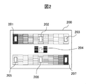
- FIG. 2 is a diagram illustrating an example of the gray scale chart 101.
- Reference numeral 200 denotes a display image displayed on a display unit such as a viewfinder, and reference numerals 201 to 207 denote markers.
- the gray scale chart 101 was photographed in the TV camera apparatus control system in the case of performing the color signal adjustment work described with reference to FIG.
- the captured image of the gray scale chart is such that frame-shaped markers 201 to 207 for adjusting the angle of view superimposed on the output signal of the video display device or TV camera device called a viewfinder overlap with a specific portion of the reference chart.
- the angle of view is adjusted by an operator or the like.
- the angle-of-view angle adjustment markers 201 to 207 are superimposed only on the picture output of the video display device and the CCU (and the MCCU), and are not superimposed on the main line signal.
- the signal level of the video signal in the area portion in the markers 201 to 207 is detected, and video detection processing described later is performed.
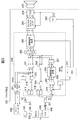
- FIG. 3 is a block diagram showing a system configuration for explaining a TV camera apparatus control system according to an embodiment of the present invention.
- FIG. 3 is a block diagram specifically showing the configuration of the slave.
- Reference numeral 300 is an FPGA (Field Programmable Gate Array) of the slave 103, 321 is an input / output terminal for connecting the transmission line 106 coupled to the CCU 109, 331 is an HD-SDI signal output terminal, 341 is a CPU (Central Processing Unit), and 342 is timing.
- FPGA Field Programmable Gate Array
- a generator (TG) 343 is an analog front end that preprocesses electrical signals input from the CCD 344 (noise removal, level adjustment, AD conversion, etc.) and outputs a digital video signal to the video signal processing unit 305 of the FPGA 300.
- Reference numeral 345 denotes a lens unit
- 344 denotes a CCD (Charge Coupled Device) that converts an object image (reference chart) incident through the lens unit 345 and outputs the electric signal
- 350 denotes a viewfinder
- 351 denotes a marker superimposing unit 311 Blue difference (Pb) signal and red difference (Pr) signal and 3 A luminance input from the synchronization mixing unit 314 (Y) signals, respectively D-A converter which outputs the viewfinder 350 is converted into digital data (D-A).
- 301 is a serial-parallel converter (SP)
- 302 is a decoder
- 303 is a data separation unit
- 304 is a video detection processing unit
- 305 is a video signal processing unit
- 306 is a matrix unit
- 307 is a decoder
- 308 Is a color signal generator
- 309 is a CPU data superimposing unit
- 310 is a parallel-serial converter (PS)
- 311 is a marker superimposing unit
- 312 is a color signal generating unit
- 313 is a parallel-serial converter (PS).
- 314 is a ternary synchronization mixer.
- the slave 104, the CCU 110, the transmission line 107, and the transmission line 112 shown in FIG. 1 are omitted for easier explanation.
- the master 102 and the MCCU 108 are coupled by a transmission line 105
- the slave 103 and the CCU 109 are coupled by a transmission line 106
- the MCCU 108 and the CCU 109 are coupled by a transmission line 111.
- the master 102 and the slave 103 simultaneously shoot the gray scale chart 101 and adjust the angle of view.
- the master 102 predefines black level, white level, gain level, flare level, gamma level, color difference adjustment matrix, etc.
- the adjusted video signal is output to the MCCU 108 via the transmission line 105.
- the MCCU 108 outputs the input adjusted video signal to the slave 103 via the transmission line 111, the CCU 109, and the transmission line 106.
- the slave 103 also adjusts the angle of view using a gray scale image captured at the same time as the master 102, and after adjusting the angle of view, the signal level of the image signal input from the master 102 and the image captured by the own TV camera device. Color signal adjustment is performed so that the signal level matches.
- the video signal to be compared and adjusted by the slave 103 is a video signal of an area portion in the marker used at the time of adjusting the angle of view, so the video signal transmitted from the MCCU 108 to the slave 103 via the CCU 103 is the angle of view. Only the video signal of the area in the marker used at the time of adjustment may be used.
- the video signal output from the master 103 is transmitted to the FPGA 300 of the slave 103 via the transmission line 111, the CCU 109, the transmission line 106, and the input / output terminal 321.
- the transmitted video signal is, for example, an HD-SDI format signal.
- the video signal input to the FPGA 300 is input to the serial-parallel converter 301.
- the serial-parallel converter 301 converts the received HD-SDI signal from a serial signal to a parallel signal, outputs a luminance signal and a color signal to the decoder 302, and outputs the color signal to the data separation unit 303.
- the decoder 302 generates a red signal, a green signal, and a blue signal from the luminance signal and the color signal, and outputs them to the image detection processing unit 304.
- the data separation unit 303 separates various set value data (black level, gain level, flare level, gamma level, masking, etc.) of the master 102 superimposed on the input color signal and outputs the separated data to the CPU 341.
- the CPU 341 sets data of the FPGA 300, the analog front end 343, and the timing generator 342 so that various settings of the slave 103 are the same as the data input from the master 102 side.
- the various setting values such as the black level, white level (gain level), flare level, gamma level, and color difference matrix of the master 102 and the slave 103 are all the same.
- fine adjustment processing of various setting values of the slave 103 is performed. This fine adjustment processing is performed in order to absorb errors generated due to performance variations of electronic circuit components such as ICs used in individual TV camera devices.
- the CCD 344 receives the reference chart (reference subject image) 101 (see FIGS. 1 and 2) simultaneously with the master 102 via the lens unit 345 and converts the incident light into red, green, and The electric signals are converted into blue electric signals and output to the analog front end 343.
- the analog front end 343 preprocesses the input electrical signal for each of red, green, and blue, and outputs a red signal, a green signal, and a blue signal to the video signal 305 of the FPGA 300, respectively.
- the CPU 341 controls the analog front end 343, the timing generator 342, and the FPGA 300 according to predetermined software.
- the timing generator 342 generates a predetermined clock signal (CLK) and synchronizes the processing timings of the CCD 344 and the analog front end 343.
- CLK predetermined clock signal
- the video signal processing unit 305 performs gamma level correction, DTL correction, knee correction, masking correction, black offset, white clip, and other video signals for each of red, green, and blue of the video signal input from the analog front end 343. Processing is performed, and each of the red signal, the green signal, and the blue signal is output to the matrix unit 306.
- the matrix unit 306 performs matrix processing on the input red signal, green signal, and blue signal, and outputs a luminance (Y) signal, a blue difference (Pb) signal, and a red difference (Pr) signal.
- the matrix unit 306 outputs the luminance signal, the blue color difference signal, and the red color difference signal to the marker superimposing unit 311 and also to the decoder 307, respectively.
- the matrix unit 306 outputs the luminance signal to the parallel-serial converter 310, and outputs the blue color difference signal and the red color difference signal to the color signal generation unit 308, respectively.
- the color signal generation unit 308 generates a color signal from the input blue difference signal and red difference signal and outputs the color signal to the CPU data superimposing unit 309.
- the CPU data superimposing unit 309 superimposes CPU data on the input color signal and outputs it to the parallel-serial converter 310.
- the parallel-serial converter 310 converts the input luminance signal and color signal into an HD-SDI signal of serial data, and outputs it to the CCU 109 via the HD-SDI input / output terminal 321 and the transmission line 106.
- the marker superimposing unit 311 superimposes the marker as shown in FIG. 2 on the input luminance signal, blue difference signal, and red difference signal, and converts the luminance signal on which the marker is superimposed into a parallel-serial converter 313 and a matrix unit. To 314. In addition, the marker superimposing unit 311 outputs the blue color difference signal and the red color difference signal on which the marker is superimposed to the color signal generation unit 312 and the DA converter 351.
- the color signal generation unit 312 generates a color signal based on the input blue difference signal and red color difference signal, and outputs the color signal to the parallel-serial converter 313.
- the parallel-serial converter 313 converts the input luminance signal and color signal into an HD-SDI signal of serial data and outputs it to the HD-SDI output terminal 331.
- the ternary synchronization mixing unit 314 adds the composite synchronization signal to the blanking period of the input color signal, and outputs it to the DA converter 351.
- the DA converter 351 converts the input luminance signal, blue color difference signal, and red color difference signal into analog signals, respectively, and outputs them to the viewfinder 350, respectively.
- the viewfinder 350 generates and displays a video signal based on the input luminance signal, blue color difference signal, and red color difference signal.
- the viewfinder 350 is used when adjusting the angle of view as described with reference to FIGS.
- the marker superimposing unit 311 superimposes the marker on the captured image of the reference chart.
- the operator can adjust the angle of view.
- the fine adjustment process will be described.
- the video signal of the main line video of the slave 103 (own TV camera device) is input to the video detection processing unit 304 from the decoder 307.
- the video detection processing unit 304 based on the block configuration diagram of FIG. 3 and the processing flowcharts shown in FIG. 4 to FIG. (White level), flare level, and gamma level are finely adjusted.
- fine adjustment processing of masking is performed based on the video signal obtained as a result of photographing the color chart.
- FIG. 4 is a flowchart showing an embodiment of the present invention of a processing procedure when the video detection processing unit 304 on the slave side adjusts the black level, gain level (white level), flare level, and gamma level. .
- the above five items excluding masking are adjusted using the gray scale chart 101 as the reference chart.
- the level of the video signal of the master 102 is detected and subtracted from the level of the main line signal. Thereafter, when the subtraction result falls below the threshold value, the fine adjustment of the item is completed.
- FIG. 4 first, as described with reference to FIGS.
- the master 102 and the slave 103 simultaneously shoot the same gray scale chart 101, respectively acquire it as a video signal of the video main line, and adjust the angle of view.
- the master 102 corrects the black level, white level (gain level), flare level, and gamma level, and transmits the transmission line 105, MCCU 108, transmission line 111, CCU 109, transmission line 106, and input line.
- the data is output to the FPGA 300 (video detection processing unit 304) of the slave 103 via the output terminal 321.
- the color signal adjustment of the present invention is performed using the video signal in the area of the markers 201 to 207 at the time of adjusting the angle of view.
- the video detection processing unit 304 of the FPGA 300 of the slave 103 performs black level adjustment in step S401, and performs white level (gain level) adjustment in step S402. In step S403, flare level adjustment is performed, and in step S404, the gamma level is adjusted. Steps S401 to S404 in FIG. 4 will be further described with reference to FIGS.
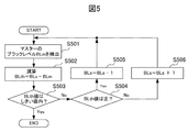
- FIG. 5 is a flowchart showing a processing procedure for adjusting the black level according to the embodiment of the present invention.
- step S501 the black level value BLm of the video signal of the master 102 input to the FPGA 300 is detected from the input / output terminal 321, and the process proceeds to step S502.
- step S502 the black level value BLm of the video signal of the master 102 is subtracted from the black level value BLs of the video signal input from the decoder 307 of the own TV camera device to calculate a subtraction value BLth, and the process proceeds to step S503. Transition.
- step S503 it is determined whether or not the subtraction value BLth is within a predetermined threshold value of a predetermined black level. If it is determined that the subtraction value BLth is within the predetermined threshold value, the black level adjustment is terminated, and the process proceeds to step S402 in FIG. If it is determined that the subtracted value BLth is outside the predetermined threshold value, the process proceeds to step S504. In step S504, whether the subtraction value BLth is positive or negative is determined. If the subtraction value BLth is positive, the process proceeds to step S505. If the subtraction value BLth is negative, the process proceeds to step S506.
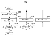
- FIG. 6 is a flowchart showing a processing procedure for adjusting the white level according to the embodiment of the present invention.
- step S601 the white level value WLm of the video signal of the master 102 input to the FPGA 300 is detected from the input / output terminal 321, and the process proceeds to step S602.
- step S602 the white level value WLm of the video signal of the master 102 is subtracted from the white level value WLs of the video signal input from the decoder 307 of the own TV camera device to calculate a subtraction value WLth, and the process proceeds to step S603. Transition.
- step S603 it is determined whether or not the subtraction value WLth is within a predetermined threshold value of a predetermined white level. If it is determined that the subtraction value WLth is within the predetermined threshold value, the white level adjustment is terminated, and the process proceeds to step S403 in FIG. If it is determined that the subtracted value WLth is outside the predetermined threshold value, the process proceeds to step S604. In step S604, whether the subtraction value WLth is positive or negative is determined. If the subtraction value WLth is positive, the process proceeds to step S605. If the subtraction value WLth is negative, the process proceeds to step S606.
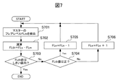
- FIG. 7 is a flowchart showing a processing procedure for adjusting a flare level according to an embodiment of the present invention.
- step S701 the flare level value FLm of the video signal of the master 102 input to the FPGA 300 is detected from the input / output terminal 321, and the process proceeds to step S702.
- step S702 the flare level value FLm of the video signal of the master 102 is subtracted from the flare level value FLs of the video signal input from the decoder 307 of the own TV camera device to calculate a subtraction value FLth, and the process proceeds to step S703. Transition.
- FIG. 8 is a flowchart showing a processing procedure for adjusting the gamma level according to one embodiment of the present invention.
- step S801 the gamma level value GLm of the video signal of the master 102 input to the FPGA 300 is detected from the input / output terminal 321, and the process proceeds to step S802.
- step S802 the gamma level value GLm of the video signal of the master 102 is subtracted from the gamma level value GLs of the video signal input from the decoder 307 of the own TV camera device to calculate the subtraction value GLth, and the process proceeds to step S803. Transition.
- step S803 it is determined whether or not the subtraction value GLth is within a predetermined threshold value of a predetermined gamma level. When it is determined that the subtraction value GLth is within the predetermined threshold value, the adjustment of the gamma level is terminated, and the processing of FIG. 4 is terminated. If it is determined that the subtraction value GLth is outside the predetermined threshold, the process proceeds to step S804. In step S804, whether the subtraction value GLth is positive or negative is determined. If the subtraction value GLth is positive, the process proceeds to step S805. If the subtraction value GLth is negative, the process proceeds to step S806.
- the video detection processing unit 304 finishes the fine adjustment of the black, gain level, flare level, and gamma level to the CPU 341 to superimpose the marker.
- a warning message is superimposed on the marker superimposing unit 311.
- a warning message is displayed on the viewfinder 350, for example, “Please change the Grayscale chart into the Color Chart.”, Overlaid on the captured image of the grayscale chart 101.
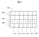
- FIG. 10 is a diagram illustrating an example of a color chart.
- Reference numeral 1001 denotes a display image displayed on a display unit such as a viewfinder.
- the display video 1001 is a chart in which different colors are arranged for each rectangular frame having the same shape and the same area. For example, two rows of the row 1002 are intermediate colors having different colors.
- the row 1003 includes, from the left, blue (B), green (G), red (R), yellow (Ye), magenta (Mg), cyan (Cy), three primary colors and their complementary colors. Is arranged. Further, a gray scale is arranged in the row 1004.
- 1011 is blue (B)
- 1012 is green (G)
- 1013 is red (R)
- 1014 is yellow (Ye)
- 1015 is magenta (Mg)
- 1016 is cyan (Cy). Note that the number of colors (number of rows and columns), the order of colors to be arranged, and the like are arbitrary.
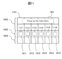
- FIG. 11 is a diagram for explaining angle-of-view adjustment of each TV camera device using the color chart of one embodiment of the present invention.
- Reference numeral 1101 denotes a display image displayed on a display unit such as a viewfinder, and 1111 to 1116 denote markers.
- the angle of view is adjusted. Therefore, after exchanging the reference chart, first, each TV camera device (master 102, slave 103, 104) takes a color chart. For example, as shown in message 903 in FIG.
- the image of the color chart taken is an angle of view superimposed on an output signal of a video display device called a viewfinder or a TV camera device.
- the angle of view is adjusted by an operator or the like so that the frame-shaped markers 1111 to 1116 for adjustment overlap a specific portion of the reference chart (in the case of a color chart, the area of the three primary colors and its complementary colors).
- the markers 1111 to 1116 for adjusting the angle of view are superimposed only on the picture output of the video display device and the CCU (and MCCU), and are not superimposed on the main line signal.
- the signal level of the video signal in the area portion in the markers 1111 to 1116 is detected, and video detection processing described later is performed.
- the warning message is not displayed after the angle of view adjustment is completed.
- the master 102 and the slave 103 simultaneously shoot the same color chart, acquire each as a video signal of the video main line, and adjust the angle of view.
- the master 102 adjusts six parameters to be described later, and transmits the FPGA 300 (video detection) of the slave 103 via the transmission line 105, the MCCU 108, the transmission line 111, the CCU 109, the transmission line 106, and the input / output terminal 321.
- the processing unit 304 To the processing unit 304).
- the masking parameters of the present invention are adjusted using the video signals in the areas of the markers 1111 to 1116 when the angle of view is adjusted.
- the color signal adjustment process is finished.
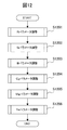
- FIG. 12 is a flowchart showing an embodiment of the present invention of a processing procedure when the slave-side video detection processing unit 304 adjusts a masking parameter. That is, in FIG. 12, the R (red) parameter is adjusted in step S1201, the G (green) parameter is adjusted in step S1202, and the B (blue) parameter is adjusted in step S1203. Further, the Cy (cyan) parameter is adjusted in step S1204, the Mg (magenta) parameter is adjusted in step S1205, and the Ye (yellow) parameter is adjusted in step S1206. Note that the processing of steps S1201 to S1206 need not be performed in the order shown in FIG. 12, and may be performed in any order.
- Steps S1201 to S1206 in FIG. 12 will be further described with reference to FIGS.
- FIG. 13 is a flowchart showing a processing procedure for adjusting the red level according to the embodiment of the present invention.
- step S1301 the red level value RcLm of the video signal of the master 102 input to the FPGA 300 is detected from the input / output terminal 321, and the process proceeds to step S1302.
- step S1302 the red level value RcLm of the video signal of the master 102 is subtracted from the red level value RcLs of the video signal input from the decoder 307 of the own TV camera device to calculate a subtraction value RcLth, and the process proceeds to step S1303. Transition.
- step S1303 it is determined whether or not the subtraction value RcLth is within a predetermined threshold value of a red level. If it is determined that the subtraction value RcLth is within the predetermined threshold value, the red level adjustment is terminated, and the process proceeds to step S1202 in FIG. If the subtraction value RcLth is determined to be outside the predetermined threshold value, the process proceeds to step S1304. In step S1304, whether the subtraction value RcLth is positive or negative is determined. If the subtraction value RcLth is positive, the process proceeds to step S1305. If the subtraction value RcLth is negative, the process proceeds to step S1306.
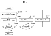
- FIG. 14 is a flowchart showing a processing procedure for adjusting the green level according to the embodiment of the present invention.
- step S1401 the red level value GcLm of the video signal of the master 102 input to the FPGA 300 is detected from the input / output terminal 321, and the process proceeds to step S1402.
- step S1402 the green level value GcLm of the video signal of the master 102 is subtracted from the green level value GcLs of the video signal input from the decoder 307 of the own TV camera device to calculate a subtraction value GcLth, and the process proceeds to step S1403. Transition.
- step S1403 it is determined whether the subtraction value GcLth is within a predetermined threshold value of a predetermined green level. If it is determined that the subtraction value GcLth is within the predetermined threshold value, the green level adjustment is terminated, and the process proceeds to step S1203 in FIG. If it is determined that the subtraction value GcLth is outside the predetermined threshold, the process proceeds to step S1404. In step S1404, whether the subtraction value GcLth is positive or negative is determined. If the subtraction value GcLth is positive, the process proceeds to step S1405. If the subtraction value GcLth is negative, the process proceeds to step S1406.
- FIG. 15 is a flowchart showing a processing procedure for adjusting the blue level according to the embodiment of the present invention.
- step S1501 the blue level value BcLm of the video signal of the master 102 input to the FPGA 300 is detected from the input / output terminal 321, and the process proceeds to step S1502.
- step S1502 the blue level value BcLm of the video signal of the master 102 is subtracted from the blue level value BcLs of the video signal input from the decoder 307 of the own TV camera device to calculate a subtraction value BcLth, and the process proceeds to step S1503. Transition.
- step S1503 it is determined whether the subtraction value BcLth is within a predetermined threshold value of a predetermined blue level. If it is determined that the subtraction value BcLth is within the predetermined threshold value, the blue level adjustment is terminated, and the process proceeds to step S1204 in FIG. If it is determined that the subtraction value BcLth is outside the predetermined threshold, the process proceeds to step S1504. In step S1504, whether the subtraction value BcLth is positive or negative is determined. If the subtraction value BcLth is positive, the process proceeds to step S1505. If the subtraction value BcLth is negative, the process proceeds to step S1506.
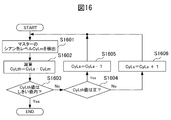
- FIG. 16 is a flowchart showing a processing procedure for adjusting the cyan color level according to one embodiment of the present invention.
- step S1601 the cyan color level value CyLm of the video signal of the master 102 input to the FPGA 300 is detected from the input / output terminal 321, and the process proceeds to step S1602.
- step S1602 the cyan color level value CyLm of the video signal of the master 102 is subtracted from the cyan color level value CyLs of the video signal input from the decoder 307 of the own TV camera device, and a subtraction value CyLth is calculated.
- Migrate processing the cyan color level value CyLm of the video signal of the master 102 input to the FPGA 300 is detected from the input / output terminal 321, and the process proceeds to step S1602.
- step S1602 the cyan color level value CyLm of the video signal of the master 102 is subtracted from the cyan color level value CyLs of the video signal input from the decoder 307 of the own TV camera device
- step S1603 it is determined whether or not the subtraction value CyLth is within a predetermined threshold of cyan bell. If it is determined that the subtraction value CyLth is within the predetermined threshold, the cyan color level adjustment is terminated, and the process proceeds to step S1205 in FIG. If it is determined that the subtraction value CyLth is outside the predetermined threshold value, the process proceeds to step S1604. In step S1604, whether the subtraction value CyLth is positive or negative is determined. If the subtraction value CyLth is positive, the process proceeds to step S1605. If the subtraction value CyLth is negative, the process proceeds to step S1606.
- FIG. 17 is a flowchart showing a processing procedure for adjusting the cyan color level according to one embodiment of the present invention.
- step S1701 the cyan color level value MgLm of the video signal of the master 102 input to the FPGA 300 is detected from the input / output terminal 321, and the process proceeds to step S1702.
- step S1702 the magenta color level value MgLm of the video signal of the master 102 is subtracted from the magenta color level value MgLs of the video signal input from the decoder 307 of the own TV camera device, and a subtraction value MgLth is calculated. Migrate processing.
- step S1703 it is determined whether or not the subtraction value MgLth is within a predetermined threshold value of a magenta bell. If it is determined that the subtraction value MgLth is within the predetermined threshold, the magenta color level adjustment is terminated, and the process proceeds to step S1206 in FIG. If the subtraction value MgLth is determined to be outside the predetermined threshold value, the process proceeds to step S1704. In step S1704, whether the subtraction value MgLth is positive or negative is determined. If the subtraction value MgLth is positive, the process proceeds to step S1705. If the subtraction value MgLth is negative, the process proceeds to step S1706.
- FIG. 18 is a flowchart showing a processing procedure for adjusting the yellow level according to one embodiment of the present invention.
- step S1801 the yellow level value YeLm of the video signal of the master 102 input to the FPGA 300 is detected from the input / output terminal 321, and the process proceeds to step S1802.
- step S1802 the yellow level value YeLm of the video signal of the master 102 is subtracted from the yellow level value YeLs of the video signal input from the decoder 307 of the own TV camera device to calculate a subtraction value YeLth, and the process proceeds to step S1803. Transition.
- step S1803 it is determined whether or not the subtraction value YeLth is within a predetermined threshold of yellow bell. If it is determined that the subtraction value YeLth is within the predetermined threshold value, the magenta color level adjustment is terminated, and the processing of FIG. If it is determined that the subtraction value YeLth is outside the predetermined threshold value, the process proceeds to step S1804. In step S1804, whether the subtraction value YeLth is positive or negative is determined. If the subtraction value YeLth is positive, the process proceeds to step S1705. If the subtraction value YeLth is negative, the process proceeds to step S1806.
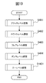
- step S1901 of FIG. 19 is added after the fine adjustment by the gray scale chart of FIG. That is, the gray level chart is used to adjust the knee level in addition to the fine adjustment processing of the black level, gain level (white level), flare level, and gamma level.
- fine adjustment processing of masking is performed based on the video signal obtained as a result of photographing the color chart.
- FIG. 4 is a flowchart showing an embodiment of the present invention of the processing procedure when the video detection processing unit 304 on the slave side adjusts the black level, gain level (white level), flare level, and gamma level. .
- the above five items excluding masking are adjusted using the gray scale chart 101 as the reference chart.
- the knee characteristic can be further adjusted, so that the variation of the color signal adjustment can be reduced in addition to the effects of FIGS.
- FIG. 20 is a block diagram showing the configuration of an embodiment of the TV camera device control system when performing the color signal adjustment work of the present invention.
- 2002 is a master, and 2003 and 2004 are slaves.
- Reference numerals 2005 and 2006 denote transmission lines such as coaxial cables.
- FIGS. 1 to 18 an example of system operation for connecting a camera control device (MCCU, CCU) and a TV camera device has been described.
- the present invention can be applied to the operation of only the TV camera device.
- FIG. 20 shows an application example of the present invention when only the TV camera device is operated.
- the output signal of the master 2002 is input to the slaves 2003 and 2004 via the transmission lines 2005 and 2006.
- each of the slaves 2003 and 2004 sets the TV camera device itself based on various setting data extracted from the output signal of the master 2002, and performs the above-described processing (black, gain level, flare level, gamma level). , Knee level, and masking).
- an embodiment of the present invention is a television camera apparatus that spectrally divides a subject image incident through a lens unit and irradiates the solid-state image sensor to convert it into a video signal.
- a video signal obtained by multiplexing the color signal-adjusted red, green, and blue channel signals is input and matched with the value of the input video signal.
- This is a television camera device for adjusting color signals.
- the television camera device simultaneously shoots a reference chart taken for the color signal adjustment by the television camera device serving as a reference for the color signal adjustment and matches the value of the input video signal.
- the color signal is adjusted.
- the reference chart is provided with a plurality of predetermined areas, and a television camera device serving as a reference for the color signal adjustment by adjusting the shooting one of the areas to match the position of the predetermined marker.
- the color signal is adjusted after the angle of view is adjusted so as to match the angle of view.
- the television camera device is a video signal obtained by multiplexing the color signal adjusted red, green, and blue channel signals from the television camera device serving as a reference for the color signal adjustment. It is input as a signal in HD-SDI (High Definition TeleVision-Serial Digital Interface) format.
- HD-SDI High Definition TeleVision-Serial Digital Interface
- a reference chart is photographed, adjusted to a predetermined angle of view, a black level, a white level (gain level), a flare level, a gamma ( ⁇ ) level, and a color difference matrix
- the first television camera device for adjusting the image, the transmission line, and the reference chart are photographed at the same time as the first television camera device and adjusted to the predetermined angle of view. Adjusting the video level of the video signal input from the camera device via the transmission line and the video signal of the own device so as to match the input video signal, black level, white level, flare level,
- a television camera apparatus control system comprising: a second television camera apparatus that adjusts a gamma level and a color difference matrix.
- the video signal input to the second television camera device via the transmission line is It is a return signal of the camera control apparatus of a 1st television camera apparatus.
- the transmission line is an HD-SDI (High Definition TeleVision-Serial Digital Interface) format signal.
- a reference chart is taken, adjusted to a predetermined angle of view, and a black level, a white level, a flare level, a gamma level, a knee, and a color difference matrix are adjusted.
- the television camera device, the transmission line, and the reference chart are photographed simultaneously with the first television camera device, adjusted to the predetermined angle of view, and transmitted from the first television camera device.
- Adjust the video level of the video signal input through the track and the video signal of the own machine so as to match the input video signal, black level, white level, flare level, gamma level, knee, And a second television camera device that adjusts the color difference matrix.
- the video signal input to the second television camera device via the transmission line is It is a return signal of the camera control apparatus of a 1st television camera apparatus.
- the transmission line is an HD-SDI (High Definition TeleVision-Serial Digital Interface) format signal.
Landscapes
- Engineering & Computer Science (AREA)
- Multimedia (AREA)
- Signal Processing (AREA)
- Health & Medical Sciences (AREA)
- Biomedical Technology (AREA)
- General Health & Medical Sciences (AREA)
- Studio Devices (AREA)
- Color Television Image Signal Generators (AREA)
- Processing Of Color Television Signals (AREA)
- Testing, Inspecting, Measuring Of Stereoscopic Televisions And Televisions (AREA)
Abstract
Priority Applications (3)
| Application Number | Priority Date | Filing Date | Title |
|---|---|---|---|
| BRPI1011771-7A BRPI1011771B1 (pt) | 2009-06-19 | 2010-06-16 | Sistema de controle de câmera de televisão |
| US13/378,414 US8564671B2 (en) | 2009-06-19 | 2010-06-16 | Television camera and television camera control system |
| CN201080027317.4A CN102461176B (zh) | 2009-06-19 | 2010-06-16 | 电视摄像机装置以及电视摄像机装置控制系统 |
Applications Claiming Priority (2)
| Application Number | Priority Date | Filing Date | Title |
|---|---|---|---|
| JP2009-146436 | 2009-06-19 | ||
| JP2009146436A JP5139374B2 (ja) | 2009-06-19 | 2009-06-19 | テレビジョンカメラ装置制御システム |
Publications (1)
| Publication Number | Publication Date |
|---|---|
| WO2010146851A1 true WO2010146851A1 (fr) | 2010-12-23 |
Family
ID=43356182
Family Applications (1)
| Application Number | Title | Priority Date | Filing Date |
|---|---|---|---|
| PCT/JP2010/004003 Ceased WO2010146851A1 (fr) | 2009-06-19 | 2010-06-16 | Caméra de télévision et système de commande de caméra de télévision |
Country Status (5)
| Country | Link |
|---|---|
| US (1) | US8564671B2 (fr) |
| JP (1) | JP5139374B2 (fr) |
| CN (1) | CN102461176B (fr) |
| BR (1) | BRPI1011771B1 (fr) |
| WO (1) | WO2010146851A1 (fr) |
Families Citing this family (9)
| Publication number | Priority date | Publication date | Assignee | Title |
|---|---|---|---|---|
| EP2699002A4 (fr) * | 2011-04-11 | 2014-09-10 | Fuji Film Corp | Dispositif de conversion vidéo, système photographique d'un système vidéo employant ce dispositif, procédé de conversion vidéo et programme de conversion vidéo |
| WO2014155814A1 (fr) | 2013-03-27 | 2014-10-02 | 富士フイルム株式会社 | Appareil de capture d'image, procédé d'étalonnage, programme et support d'enregistrement |
| CN104735368B (zh) * | 2013-12-19 | 2018-08-14 | 比亚迪股份有限公司 | Cmos传感器及其图像中黑电平的调整方法和装置 |
| CN103747243A (zh) * | 2013-12-31 | 2014-04-23 | 深圳市华星光电技术有限公司 | 基于ccd相机的lcd全灰阶数据采集方法 |
| JP6482232B2 (ja) * | 2014-10-16 | 2019-03-13 | 日本放送協会 | カラーバー生成装置および表示システム |
| JP6678045B2 (ja) * | 2016-03-08 | 2020-04-08 | 日本放送協会 | 測定装置 |
| US10182180B2 (en) | 2016-09-07 | 2019-01-15 | Peau Productions, Inc. | Multiple camera control system |
| CN107197240B (zh) * | 2017-07-06 | 2019-02-22 | 惠科股份有限公司 | 检测设备的色差调整方法以及装置 |
| CN116391359A (zh) * | 2020-11-13 | 2023-07-04 | 索尼集团公司 | 信息处理系统、信息处理装置、信息处理方法、信息处理程序、成像装置、控制成像装置的方法和控制程序 |
Citations (2)
| Publication number | Priority date | Publication date | Assignee | Title |
|---|---|---|---|---|
| JPS5820092A (ja) * | 1981-07-29 | 1983-02-05 | Toshiba Corp | カラ−テレビジヨンカメラの自動調整方式 |
| JP2008206090A (ja) * | 2007-02-22 | 2008-09-04 | Fujifilm Corp | 撮影装置及び撮影システム |
Family Cites Families (4)
| Publication number | Priority date | Publication date | Assignee | Title |
|---|---|---|---|---|
| JPS59100685A (ja) * | 1982-11-30 | 1984-06-09 | Toshiba Corp | カラ−テレビジヨンカメラ装置 |
| JPS59196679A (ja) * | 1983-04-22 | 1984-11-08 | Toshiba Corp | 複数のカラ−テレビジヨンカメラのホワイトバランス調整方式 |
| JPH06311419A (ja) | 1993-04-26 | 1994-11-04 | Hitachi Denshi Ltd | テレビジョンカメラの集中制御装置 |
| US20060268119A1 (en) * | 2005-05-27 | 2006-11-30 | Akiyoshi Sugawara | Television camera, television camera system and image pickup control method |
-
2009
- 2009-06-19 JP JP2009146436A patent/JP5139374B2/ja active Active
-
2010
- 2010-06-16 WO PCT/JP2010/004003 patent/WO2010146851A1/fr not_active Ceased
- 2010-06-16 US US13/378,414 patent/US8564671B2/en not_active Expired - Fee Related
- 2010-06-16 BR BRPI1011771-7A patent/BRPI1011771B1/pt not_active IP Right Cessation
- 2010-06-16 CN CN201080027317.4A patent/CN102461176B/zh not_active Expired - Fee Related
Patent Citations (2)
| Publication number | Priority date | Publication date | Assignee | Title |
|---|---|---|---|---|
| JPS5820092A (ja) * | 1981-07-29 | 1983-02-05 | Toshiba Corp | カラ−テレビジヨンカメラの自動調整方式 |
| JP2008206090A (ja) * | 2007-02-22 | 2008-09-04 | Fujifilm Corp | 撮影装置及び撮影システム |
Also Published As
| Publication number | Publication date |
|---|---|
| JP5139374B2 (ja) | 2013-02-06 |
| US20120092505A1 (en) | 2012-04-19 |
| BRPI1011771B1 (pt) | 2021-03-23 |
| BRPI1011771A2 (pt) | 2016-03-29 |
| JP2011004239A (ja) | 2011-01-06 |
| CN102461176B (zh) | 2015-03-25 |
| US8564671B2 (en) | 2013-10-22 |
| CN102461176A (zh) | 2012-05-16 |
Similar Documents
| Publication | Publication Date | Title |
|---|---|---|
| JP5139374B2 (ja) | テレビジョンカメラ装置制御システム | |
| JP6032919B2 (ja) | 画像処理装置 | |
| US9001227B2 (en) | Combining data from multiple image sensors | |
| US11032447B2 (en) | Method and system for automatically synchronizing audio-video inputs in a multi camera environment | |
| US8896668B2 (en) | Combining data from multiple image sensors | |
| JP2011216948A (ja) | カメラシステム、映像処理装置及びカメラ装置 | |
| WO2008112053A3 (fr) | Procédé de fonctionnement d'appareil photo à deux objectifs pour augmenter des images | |
| JP6233424B2 (ja) | 撮像システムおよび撮像方法 | |
| CN107592452B (zh) | 一种全景音视频采集设备及方法 | |
| WO2017086348A1 (fr) | Système à appareils photo multiples, procédé de commande de système à appareils photo multiples, et appareil photo | |
| WO2017084172A1 (fr) | Procédé et dispositif de séparation de vidéo retransmise et de vidéo affichée sur site | |
| US8548043B2 (en) | Signal transmitting device and signal transmitting method | |
| JP4731229B2 (ja) | デジタルカメラ | |
| CN102111548A (zh) | 摄像机适配器盒和摄像机控制方法 | |
| CN102104763B (zh) | 视频信号处理器和视频信号处理方法 | |
| JP2006217384A (ja) | テレビカメラシステム、制御装置およびカメラ | |
| JPH09238277A (ja) | カメラ制御装置 | |
| JP7140472B2 (ja) | 撮像装置の設置方法および制御手段 | |
| Lin et al. | A camera array system based on DSLR cameras for autostereoscopic prints | |
| JP2006180293A (ja) | ヘッド分離型単板式カラーカメラ装置 | |
| JPS598990B2 (ja) | カラ−テレビジョンカメラにおける走査位置ずれ補正装置 | |
| JPH0157867B2 (fr) | ||
| JP2018014766A (ja) | 撮像システムおよび撮像方法 | |
| US10321024B2 (en) | Image capturing method and image capturing apparatus | |
| JP4029752B2 (ja) | 映像記録再生システム |
Legal Events
| Date | Code | Title | Description |
|---|---|---|---|
| WWE | Wipo information: entry into national phase |
Ref document number: 201080027317.4 Country of ref document: CN |
|
| 121 | Ep: the epo has been informed by wipo that ep was designated in this application |
Ref document number: 10789230 Country of ref document: EP Kind code of ref document: A1 |
|
| WWE | Wipo information: entry into national phase |
Ref document number: 13378414 Country of ref document: US |
|
| NENP | Non-entry into the national phase |
Ref country code: DE |
|
| 122 | Ep: pct application non-entry in european phase |
Ref document number: 10789230 Country of ref document: EP Kind code of ref document: A1 |
|
| REG | Reference to national code |
Ref country code: BR Ref legal event code: B01A Ref document number: PI1011771 Country of ref document: BR |
|
| ENP | Entry into the national phase |
Ref document number: PI1011771 Country of ref document: BR Kind code of ref document: A2 Effective date: 20111219 |