WO2011002192A2 - Véhicule à système de génération d'énergie thermoélectrique utilisant la chaleur perdue - Google Patents
Véhicule à système de génération d'énergie thermoélectrique utilisant la chaleur perdue Download PDFInfo
- Publication number
- WO2011002192A2 WO2011002192A2 PCT/KR2010/004186 KR2010004186W WO2011002192A2 WO 2011002192 A2 WO2011002192 A2 WO 2011002192A2 KR 2010004186 W KR2010004186 W KR 2010004186W WO 2011002192 A2 WO2011002192 A2 WO 2011002192A2
- Authority
- WO
- WIPO (PCT)
- Prior art keywords
- battery
- transfer channel
- sub
- engine
- main battery
- Prior art date
- Legal status (The legal status is an assumption and is not a legal conclusion. Google has not performed a legal analysis and makes no representation as to the accuracy of the status listed.)
- Ceased
Links
Images


Classifications
-
- H—ELECTRICITY
- H10—SEMICONDUCTOR DEVICES; ELECTRIC SOLID-STATE DEVICES NOT OTHERWISE PROVIDED FOR
- H10N—ELECTRIC SOLID-STATE DEVICES NOT OTHERWISE PROVIDED FOR
- H10N10/00—Thermoelectric devices comprising a junction of dissimilar materials, i.e. devices exhibiting Seebeck or Peltier effects
- H10N10/10—Thermoelectric devices comprising a junction of dissimilar materials, i.e. devices exhibiting Seebeck or Peltier effects operating with only the Peltier or Seebeck effects
- H10N10/13—Thermoelectric devices comprising a junction of dissimilar materials, i.e. devices exhibiting Seebeck or Peltier effects operating with only the Peltier or Seebeck effects characterised by the heat-exchanging means at the junction
Definitions
- the present invention is channeled to an automobile equipped with a thermoelectric power generation system using waste heat.
- the waste heat generated when the engine is driven is supplied to the thermoelectric module and channeled to a vehicle having a thermoelectric power generation system using waste heat to generate electrical energy.
- heat dissipation device Since a car generates heat when used as a moving device by using available energy such as petroleum, heat dissipation device should be installed.
- thermoelectric power generation system using waste heat aims to solve the following problems.
- thermoelectric module By using the temperature difference between the low temperature fluid and lubricating oil flowing into the engine and the high temperature fluid and lubricating oil absorbing and exhausting heat from the engine to generate heat, the electric energy is generated through the thermoelectric module to generate the energy of the vehicle. I want to increase efficiency.
- thermoelectric power system when the electric energy generated in the thermoelectric power system is charged to the battery by the temperature difference between the low temperature fluid and the lubricating oil and the high temperature fluid and the lubricating oil, the efficiency of the engine is increased by controlling the generator coupled to the engine according to the state of the battery. Let's do it.
- thermoelectric module installation area it is intended to increase energy efficiency by expanding the thermal contact area between the fluid and lubricant oil flowing into the engine and the fluid and lubricant oil discharged, and the thermoelectric module installation area.
- An automobile having a thermoelectric power generation system using waste heat includes an engine, a fluid radiator, a lubricating oil radiator, and a battery unit, and the vehicle includes a thermoelectric power generation system using waste heat of an engine.
- a fluid transfer channel part comprising an engine in which a lubrication part is formed, a low temperature transfer channel through which the heat radiated from the fluid radiator is transferred to the engine radiator, and a high temperature transfer channel through which the heat absorbed by the engine from the engine radiator is transferred to the fluid radiator.
- At least one of a fluid transfer channel part and a fluid transfer channel part comprising a low temperature transfer channel through which lubricating oil is transferred from the lubricating oil radiator to the lubricating part, a high temperature transfer channel through which lubricating oil heated by the lubricating part is transferred to the lubricating oil radiator, and Installed in one of them, the temperature difference between low temperature transfer channel and high temperature transfer channel It includes a thermoelectric module for generating the energy.
- An engine of a vehicle having a thermoelectric power generation system using waste heat according to the present invention is provided with a rotating shaft that is separable from the driving shaft of the engine and is provided with a generator connected to the battery unit, and the generator separates the driving shaft of the engine from the rotating shaft of the generator.
- the control unit is connected, the battery unit is electrically connected to the thermoelectric module, the thermoelectric module and the battery unit is preferably provided with a measuring sensor for measuring the amount of electrical energy.
- a generator is installed in an engine, a generator is connected to a control unit for controlling an electrical connection with a battery unit, and a battery unit controls an electrical connection with a thermoelectric module. It is preferable that the control unit is connected.
- the measuring sensor transmits a signal to the controller, and the controller separates the drive shaft of the engine from the rotation shaft of the generator. .
- thermoelectric power generation system using waste heat according to the present invention
- the controller when electrical energy is generated from a thermoelectric module, the controller preferably blocks the electrical connection between the generator and the battery unit.
- the measurement sensor transmits a signal to the controller, and the controller separates the drive shaft of the engine from the rotation shaft of the generator.
- control unit cut off the electrical connection of the generator and the battery unit.
- the battery unit of a vehicle having a thermoelectric power generation system using waste heat includes a main battery and a sub battery
- the main battery is electrically connected to the generator
- the control unit controls the electrical connection between the main battery and the sub battery.
- the battery unit of a vehicle having a thermoelectric power generation system using waste heat includes a main battery and a sub battery
- the main battery is electrically connected to the generator
- the control unit controls the electrical connection between the main battery and the sub battery.
- thermoelectric module of a vehicle having a thermoelectric power generation system using waste heat according to the present invention is connected only to the main battery, when the charging of the main battery is completed, the controller separates the driving shaft of the engine and the rotation shaft of the generator, and the main battery and the sub It is preferable to connect the battery to charge the sub-battery with the electric energy overcharged in the main battery.
- thermoelectric module of a vehicle having a thermoelectric power generation system using waste heat according to the present invention is connected only to a sub battery, when the charging of the sub battery is completed, the controller separates the driving shaft of the engine from the rotation shaft of the generator and controls the sub battery. It is preferable to connect the battery to charge the main battery with the electric energy overcharged in the sub battery.
- thermoelectric module of a vehicle having a thermoelectric power generation system using waste heat according to the present invention is connected to only a sub battery, when the charging of the sub battery is completed, the controller cuts off the electrical connection between the generator and the main battery, It is preferable to connect the battery to charge the main battery with the electric energy overcharged in the sub battery.
- thermoelectric module of a vehicle having a thermoelectric power generation system using waste heat according to the present invention is connected only to the main battery, when the charging of the main battery is completed, the controller cuts off the electrical connection between the generator and the main battery, and the main battery and the sub battery. It is preferable to connect the battery to charge the sub-battery with the electric energy overcharged in the main battery.
- the controller may control the drive shaft of the engine and the rotation shaft of the generator. Disconnect the main battery and connect the main battery and the sub-battery to charge the sub-battery with the overcharged electric energy in the main battery, or stop the connection between the main battery and the thermoelectric module and the sub-battery is completed before the main battery.
- the controller may separate the driving shaft of the engine and the rotation shaft of the generator, connect the main battery and the sub-battery to charge the main battery with electric energy overcharged to the sub-battery, or stop the connection of the thermoelectric module and the sub-battery.
- thermoelectric module of a vehicle having a thermoelectric power generation system using waste heat according to the present invention is connected to the main battery and the sub battery at the same time, when the main battery is completely charged before the sub battery, the control unit electrically connects the generator and the main battery.
- the main battery and the sub-battery are connected to charge the sub-battery with the overcharged electric energy in the main battery, or the main battery and the thermoelectric module are disconnected and the sub-battery is charged before the main battery,
- the control unit cuts off the electrical connection between the generator and the main battery, and connects the main battery and the sub battery to charge the main battery with electric energy overcharged to the sub battery, or to stop the connection between the thermoelectric module and the sub battery.
- the electrical device of the vehicle is preferably operated by using the electric energy of the sub-battery.
- At least one of a high temperature transfer channel or a low temperature transfer channel of a vehicle having a thermoelectric power generation system using waste heat according to the present invention divides the inside so as to be in communication with one side into which fluid flows into and the other side into which fluid flows out It is preferred that the diaphragms are spaced apart.
- thermoelectric module is preferably in thermal contact with an outer wall of the high temperature transfer channel connected to the diaphragm.
- thermoelectric module when a diaphragm is formed in a low temperature transfer channel, the thermoelectric module is preferably in thermal contact with an outer wall of the low temperature transfer channel connected to the diaphragm.
- a high temperature panel is formed outside the high temperature transfer channel of the vehicle having a thermoelectric power generation system using waste heat according to the present invention.
- an insulation panel is formed on one side of the high temperature panel of the vehicle having a thermoelectric power generation system using waste heat according to the present invention.
- a low temperature panel having a plurality of cooling fins formed in one direction is formed outside the low temperature transfer channel of the vehicle having a thermoelectric power generation system using waste heat according to the present invention.
- thermoelectric module of a vehicle having a thermoelectric power generation system using waste heat according to the present invention is closely coupled to the low temperature panel on the other side of the low temperature panel, and the high temperature panel is preferably closely coupled to the other side of the low temperature panel on one side of the thermoelectric module. .
- any one of a high temperature transfer channel or a low temperature transfer channel of a vehicle having a thermoelectric power generation system using waste heat according to the present invention is bent in a zigzag shape.
- thermoelectric power generation system using waste heat it is preferable that a plurality of conveying channels having a capillary structure are formed in the engine radiator to increase the cross-sectional area in contact with the fluid.
- thermoelectric power generation system using waste heat waste heat that is discarded by operating the thermoelectric module using a temperature difference between a fluid transfer channel formed between an engine and a radiator and a lubricating oil transfer channel formed between an engine and an oil pump. There is an effect that can be used.
- an automobile having a thermoelectric power generation system using waste heat according to the present invention may increase the temperature difference between the low temperature fluid and lubricant oil flowing into the engine and the high temperature fluid and lubricant oil discharged from the engine. There is an effect that can increase the amount of electrical energy.
- thermoelectric power generation system using waste heat increases waste heat by increasing the heat absorption rate in the thermoelectric module by increasing the heat exchange area of the low temperature fluid transfer channel and the high temperature fluid transfer channel in the fluid transfer channel and the lubricating oil transfer channel.
- thermoelectric power generation system using waste heat according to an embodiment of the present invention.
- FIG. 2 is a front sectional view of the fluid transfer channel or the lubricant transfer channel illustrated in FIG. 1.
- FIG. 3 is a side cross-sectional view of the fluid transfer channel or the lubricant transfer channel shown in FIG.
- FIG. 4 is a plan view illustrating the fluid transfer channel or the lubricant transfer channel illustrated in FIG. 1.
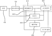
- FIG. 5 is a conceptual diagram when the generator and the battery unit are electrically connected through a control unit.
- FIG. 6 is a conceptual diagram in a case where the battery unit illustrated in FIG. 5 includes a main battery and a sub battery.
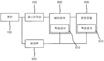
- FIG. 7 is a conceptual diagram when an engine and a generator are connected through a control unit.
- FIG. 8 is a conceptual diagram when the battery unit of FIG. 7 includes a main battery and a sub battery.
- fluid pump 300 fluid transfer channel portion
- low temperature fluid transfer channel 311 low temperature panel
- cooling fin 312 diaphragm
- lubricating oil transfer channel 510 low temperature lubricating oil transfer channel
- diaphragm 520 high temperature lubricating oil transfer channel
- thermoelectric module 522: diaphragm 600: thermoelectric module
- Control unit 910 measuring sensor
- thermoelectric power generation system using the waste heat according to the present invention.
- An automobile having a thermoelectric power generation system includes an engine heat dissipation unit 110, an engine 100 in which an lubrication unit 120 is formed, an engine heat dissipation unit 110, and a fluid radiator as shown in FIG. 1.
- the fluid transfer channel unit 300 and the fluid pump 210 formed between the 200, and the lubricant transfer channel unit 500 and the lubricant pump 410 formed between the lubrication unit 120 and the lubricant radiator 400, It consists of a thermoelectric module 600 formed between the fluid transfer channel 300 and the lubricating oil transfer channel 500 and the battery unit 800 electrically coupled to the thermoelectric module 600.
- the engine 100 obtains mechanical energy by burning gasoline, liquefied petroleum gas, and the like, and drives shafts connected to the piston by reciprocating a piston (not shown) using energy generated by burning gasoline or the like (not shown). Rotate
- the engine heat dissipation unit 110 is a fluid transfer channel unit 300 connected to the fluid radiator 200 to a space in which a cooling fluid is circulated to dissipate heat generated when the engine 100 is burned in the engine 100.
- a cooling fluid is circulated to dissipate heat generated when the engine 100 is burned in the engine 100.
- the fluid radiator 200 functions to maintain a constant temperature of the engine 100 by dissipating heat of the fluid flowing into the engine 100, and may be classified into air-cooled and water-cooled according to the type of the engine 100.
- the fluid radiator 200 used in one embodiment of the present invention uses a water-cooled radiator for cooling the engine 100 using a fluid.
- the fluid pump 210 may be installed anywhere between the engine radiator 110 and the fluid radiator 200 by forcibly transferring the fluid to the engine radiator 110. As shown in FIG. 1, the fluid transfer channel unit 300 and the fluid radiator 200 are installed.
- the position of the fluid pump 210 may be selectively changed according to the temperature of the fluid flowing out of the engine 100, the temperature of the fluid supplied to the engine heat radiating unit 110, and the like.
- Lubrication unit 120 reduces the wear of the piston reciprocating when the engine 100 is driven in the engine 100, and absorbs heat generated on the wear surface to supply the lubricant to protect the engine 100 Do it.
- the lubricating oil radiator 400 communicates with the lubricating part 120 through the lubricating oil transfer channel part 500 by dissipating heat of the lubricating oil which absorbs heat from the engine 100.
- the lubricating oil pump 410 communicates with the lubricating oil transfer channel part 500 and the lubricating oil radiator 400 to supply low temperature lubricating oil to the lubricating part 120.
- the lubricating oil transfer channel part 500 is provided.
- the fluid transfer channel unit 300 and the lubricant transfer channel unit 500 are a low temperature fluid, which is a passage through which a low temperature fluid and lubricant for cooling the engine 100 and a high temperature fluid and lubricant supplied with heat from the engine 100 move. It consists of the conveying channels 310 and 510 and the hot fluid conveying channels 320 and 520.
- the fluid transfer channel unit 300 introduces a fluid to heat dissipate heat of the engine 100 as shown in FIG. 2 or FIG. 3, in which a sectional view and a front sectional view of the fluid transfer channel or the lubricating oil transfer channel are shown. It consists of a low temperature fluid transfer channel 310, a high temperature fluid transfer channel 320, a low temperature panel 311 surrounding the low temperature fluid transfer channel 310 and a high temperature panel 421 surrounding the high temperature fluid transfer channel 320.
- the low temperature fluid transfer channel 310 communicates with one side of the engine radiator 110 and the fluid radiator 200 to transfer the fluid radiating heat from the fluid radiator 200 to the engine radiator 110, and the high temperature fluid transfer.
- the channel 320 communicates with the engine radiator 110 and the other side of the fluid radiator 200 to transfer the high temperature fluid absorbing heat from the engine 100 to the fluid radiator 200.
- Lubricating oil transfer channel 500 is a channel for introducing and flowing out lubricating oil to prevent wear of the engine 100 and to dissipate frictional heat generated during operation, as described above, one side of the lubricating unit 120 and a lubricating oil radiator ( On the other side of the low-temperature lubricating oil transfer channel 510 and the lubricating portion 120 and the lubricating oil radiator 400, the low-temperature lubricating oil flowing into the lubrication unit 120 is communicated to one side and radiated from the lubricating oil radiator 400
- the high temperature lubricant transfer channel 520 communicating with the high temperature lubricant oil absorbing heat from the engine 100 to the lubrication oil radiator 400, the low temperature panel 511 and the high temperature lubricant transfer to surround the low temperature lubricant transfer channel 510.
- the high temperature panel 521 surrounds the channel 520.
- Thermoelectric module 600 is coupled.
- thermoelectric module 600 to produce is combined.
- each thermoelectric module 600 is coupled to the fluid transfer channel unit 300 and the lubricating oil transfer channel unit 500, but the fluid transfer channel unit 300 is necessarily.
- the thermoelectric module 600 need not be coupled to each of the lubricating oil transfer channel parts 500, and the thermoelectric module 600 is coupled to only the fluid transfer channel part 300 or the lubricating oil transfer channel part 500 according to an embodiment. You can also
- the low temperature fluid transfer channel 310 and the low temperature lubricating oil transfer channel 510 and the low temperature panels 311 and 511 formed in each have similar functions and configurations, and have a high temperature fluid transfer channel 320 and a high temperature lubricant.
- the transfer channel 520 and the high temperature panels 421 and 521 formed in each of them have similar functions and configurations, so that the low temperature fluid transfer channel 310 and the high temperature fluid transfer channel 320 are respectively described below to avoid duplication of explanation. A combination of the low temperature panel 311 and the high temperature panel 321 will be described.
- the low temperature transfer channel 310 of the fluid transfer channel unit 300 is defined as a low temperature fluid transfer channel 310
- the high temperature transfer channel of the fluid transfer channel unit 300 ( 320 will be defined as the high temperature fluid transfer channel (320).
- the low temperature transfer channel 510 of the lubricating oil transfer channel part 500 is defined and used as the low temperature lubricating oil transfer channel 510
- the high temperature transfer channel 520 of the lubricating oil transfer channel part 500 is a high temperature lubricating oil transfer channel ( 520).
- thermoelectric module 600 The coupling relationship between the fluid transfer channel unit 300, the low temperature fluid transfer channel 310, the high temperature fluid transfer channel 320, and the thermoelectric module 600 will be described in detail with reference to FIG. 2. .
- the outer circumferential surface of the low temperature fluid transfer channel 310 is coupled to the low temperature panel 311 which is in thermal contact with the low temperature portion 610 of the thermoelectric module 600, and the high temperature portion of the thermoelectric module 600 is connected to the outer circumferential surface of the high temperature fluid transfer channel 320.
- the high temperature panel 321 in thermal contact with the 620 is coupled.
- the low temperature fluid transfer channel 310 formed on the outer circumferential surface of the low temperature panel 311 and the high temperature fluid transfer channel 320 formed on the outer circumferential surface of the low temperature panel 311 are radiated by the fluid radiator 200.
- a high temperature fluid endothermic by the engine 100 flows, so a temperature difference is generated between the low temperature fluid transfer channel 310 and the high temperature fluid transfer channel 320 to which the low temperature panel 311 and the high temperature panel 321 are coupled. Done.
- thermoelectric module 600 in thermal contact with the low temperature fluid transfer channel 310 and the high temperature fluid transfer channel 320 using the temperature difference is proportional to the temperature difference between the low temperature fluid transfer channel 310 and the high temperature fluid transfer channel 320. Electrical energy is generated.
- the cooling fins 3111 are coupled to the low temperature panel 311, and the heat insulation panel 3211 is coupled to the high temperature panel 321.
- the cooling fins 3111 are for increasing the surface area of the ambient air in contact with the low temperature fluid transfer channel 310, and protruding cooling fins 3111 are formed on one side of the low temperature panel 311.
- the cooling fins 3111 also serve to cool the fluid flowing into the engine.
- the cooling fins 3111 may be manufactured to cover the entire low temperature panel 311 by increasing the surface area of the low temperature panel 311 in contact with the surrounding air, but a cooling fin of this type (not shown) is formed.
- the low temperature portion 610 of the thermoelectric module 600 is coupled to the low temperature panel 311 with the cooling fins 3111 interposed therebetween, so that the low temperature portion 610 of the thermoelectric module 600 has a higher temperature when it is directly in thermal contact with the low temperature fluid transfer channel 320.
- the cooling fin 3111 is preferably formed only on the upper surface of the low temperature panel 311, as shown in FIG. ) Is preferably formed flat so that the low temperature portion 610 of the thermoelectric module 600 is in close contact.
- Cooling fins 3111 of the present invention may be configured in the shape of a variety of cross-sections, such as rectangular, circular, in the embodiment of Figures 3 to 5 pin-fin type (pin-fin type) cooling of the cross-sectional shape The pin 3111 was disposed.
- a heat insulation panel 3211 is formed on the high temperature panel 321 coupled to the outer circumferential surface of the high temperature fluid transfer channel 320.
- the high temperature fluid transfer channel 320 exchanges heat through the ambient air and the high temperature panel 321, the amount of heat exchange with the ambient air is reduced.
- the high temperature panel 321 is insulated and can be in thermal contact with the high temperature portion 620 of the thermoelectric module 600 with the temperature attracting the temperature.
- the heat insulation panel 3211 may be formed to cover the entire outer circumferential surface of the high temperature panel 321, but in this case, the high temperature portion 620 of the thermoelectric module 600 may be the high temperature panel 321 through the heat insulation panel 3211. Thermal contact.
- the high temperature portion 620 of the thermoelectric module 600 has a problem that the temperature is lower than the direct contact with the high temperature panel 321 is formed.
- the heat insulation panel 3211 may be formed in the high temperature panel 421. It formed only at the bottom.
- the shape of the heat insulating panel 3211 in the present embodiment is not necessarily limited to such a shape, and may be modified in various forms as long as it meets the purpose of blocking heat exchange between the high temperature panel 321 and the outside.
- the low temperature fluid transfer channel 310 forming the fluid transfer channel part 300 may be formed of a plurality of tubes, but when the low temperature fluid transfer channel 310 is formed of one tube, the low temperature fluid transfer channel 310 It is preferable that a plurality of septums (septum, 312) is disposed inside the low temperature fluid transfer channel 310 to allow maximum heat exchange with the periphery.
- the diaphragm 312 partitions the inside of the low temperature fluid transfer channel 310 to increase the contact area between the fluid flowing in the low temperature fluid transfer channel 310 and the low temperature fluid transfer channel 310.
- the diaphragm 312 according to the present invention increases the surface area between the low temperature panel 311 coupled to the low temperature fluid transfer channel 310 and the fluid flowing in the low temperature fluid transfer channel 310 to provide a space between the fluid and the low temperature fluid transfer channel. Increase the amount of heat exchange
- a plurality of small channels surrounded by the diaphragm and the low temperature fluid transfer channel or a small channel surrounded by the diaphragm may be formed in the low temperature fluid transfer channel 310 in which the diaphragm 312 is installed. That is, the inside of the low temperature fluid transfer channel 310 may be divided into a plurality of small channels according to the arrangement of the diaphragm 312. Fluid is transported through these small channels.
- a plurality of diaphragms 312 are installed in parallel to each other, and a technical configuration of partitioning into small channels having a rectangular pillar shape has been proposed.
- a low temperature fluid transfer channel 310 is disclosed that includes a plurality of small channels formed with a plurality of diaphragms 312 spaced in parallel.
- the high temperature fluid transfer channel 320 may be formed of a plurality of small channels, such as the low temperature fluid transfer channel 310, but when the high temperature fluid transfer channel 320 is formed of one channel, the high temperature fluid transfer channel 320 is coupled to the high temperature fluid transfer channel 320.
- the high temperature fluid transfer channel (410) is the same as the low temperature fluid transfer channel 410 so that the temperature of the high temperature unit 610 of the thermoelectric module 600 is close to the temperature of the high temperature fluid flowing inside the high temperature fluid transfer channel 320. It is preferable to arrange a plurality of septums 322 inside 320.
- the plurality of diaphragms 322 may be arranged in various forms inside the high temperature transfer channel 320, and a small channel having a plurality of various forms is formed according to the arrangement form.
- a hot fluid transfer channel 320 that includes a plurality of small channels formed with a plurality of diaphragms 322 spaced in parallel.
- the membranes 312 and 322 formed inside the low temperature fluid transfer channel 310 and the high temperature fluid transfer channel 320 may be formed in various shapes, but are shown in FIG. 3 to generate a minimum resistance to the flow of the fluid. As described above, the low-temperature fluid transfer channel 310 and the high-temperature fluid transfer channel 320 are spaced apart from each other to communicate with one side of the fluid inflow and the other side of the fluid outflow.
- the diaphragm is formed to be substantially parallel to the flow of the fluid, when the fluid flows in the low temperature fluid transfer channel 310 and the high temperature fluid transfer channel 320, the resistance is minimally generated.
- the thermoelectric module 600 may be a low temperature fluid transfer channel 310 or a high temperature fluid transfer channel ( It may be in thermal contact anywhere on the outer side of 320.
- the low temperature fluid transfer channel 310 when the low temperature fluid transfer channel 310 is in thermal contact with the outer wall of the low temperature fluid transfer channel 310 and the high temperature fluid transfer channel 320, which are connected to the diaphragm formed inside the high temperature fluid transfer channel 320, the low temperature fluid transfer channel 310. Heat exchange with the fluid flowing in the 310 and the high temperature fluid transfer channel 320 can be more smoothly.
- thermoelectric module 600 is preferably in thermal contact with the outer wall of the low temperature transfer channel 310 or the high temperature transfer channel 320 connected to the diaphragms 312 and 322.
- the fluid transfer channel part 300 includes one low temperature fluid transfer channel 310 and a high temperature fluid transfer channel 320 having a plurality of diaphragms 312 and 322 therein, but one low temperature fluid. It does not have to be made of the transport channel 310 and the hot fluid transport channel 320, it may be composed of a plurality of cold fluid transport channel 310 and the hot fluid transport channel (320).
- the diaphragms 312 and 322 are formed in both the low temperature fluid transfer channel 310 and the high temperature fluid transfer channel 320, but the diaphragm is formed in both the low temperature fluid transfer channel 310 and the high temperature fluid transfer channel 320. It is not necessary to form the 312 and 322, it may be formed only in any one of the low temperature fluid transfer channel 310 or the high temperature fluid transfer channel (320).
- the low temperature fluid transfer channel 310 and the high temperature fluid transfer channel 310 having the plurality of diaphragms 312 and 322 are formed as shown in FIG. 2, which is an embodiment of the present invention. It may be connected in a straight line form between 110, it may be formed in a variety of shapes, such as a spiral shape.
- the high temperature fluid transfer channel 320 and the low temperature fluid transfer channel 310 may be formed in a shape corresponding to each other, as shown in Figure 2 or 3 of an embodiment of the present invention.
- the high temperature fluid transfer channel 320 When the high temperature fluid transfer channel 320 is formed in a shape corresponding to the low temperature fluid transfer channel 310, the low temperature fluid transfer channel via the low temperature panel 311 and the high temperature panel 321 above and below the thermoelectric module 600.
- the 310 and the high temperature fluid transfer channel 320 are positioned to be in direct contact with each other, such that the low temperature portion 620 and the high temperature portion 610 of the thermoelectric module 600 have the largest temperature difference.
- thermoelectric module 600 can generate more electrical energy.
- the high temperature fluid transfer channel 320 and the low temperature fluid transfer channel 310 do not necessarily have to be formed in a shape corresponding to each other, and the installation position of the thermoelectric module 600, the number of installations, and the low temperature panel 311 and the high temperature panel ( It may be formed by deforming in various shapes according to the shape of the 321.
- the fluid used in the fluid transfer channel part 300 may be a coolant such as an antifreeze, but generally absorbs more heat energy from the engine 100 and releases heat faster than the fluid radiator 200. It is preferred that a fluid having is used.
- the outer circumferential surface of the low temperature lubricating oil transfer channel 510 is coupled to the low temperature panel 511 which is in thermal contact with the low temperature portion 610 of the thermoelectric module 600, and the high temperature panel 521 is coupled to the outer circumferential surface of the high temperature lubricating oil transfer channel 520.
- the high temperature part 620 of the thermoelectric module 600 is in thermal contact with the high temperature panel 521.
- the low temperature lubrication oil transfer channel 510 and the high temperature lubrication oil transfer channel 520 are installed between the lubrication unit 120 and the lubrication oil radiator 400, and the low temperature fluid transfer channel 310 and the high temperature fluid transfer channel 320 described above. ), So descriptions thereof will be omitted to avoid duplication.
- the low temperature panel 511 coupled to the low temperature lubricating oil transfer channel 510 has the same function and structure as the low temperature panel 311 coupled to the low temperature fluid transfer channel 310, the description will be given in order to avoid duplication thereof.
- the low temperature panel 311 coupled to the low temperature fluid transfer channel 310 will be replaced with the description.
- the high temperature panel 521 coupled to the outer circumferential surface of the high temperature lubricating oil transfer channel 520 also has the same structure and function as the high temperature panel 321 coupled to the high temperature fluid transfer channel 320 described above. It will be omitted.
- cooling plate (5111) coupled to the low temperature panel 511 and the heat insulating panel (5211) coupled to the high temperature panel 521 is also the cooling fin (3111) coupled to the low temperature fluid transfer channel 310 described above; Since the same function as the heat insulation panel 3211 coupled to the high temperature fluid transfer channel 320, a description thereof will be omitted to avoid duplication.
- the low temperature lubricant oil transfer channel 510 and the high temperature lubricant oil transfer channel 520 allow the lubricant to be transported with the least resistance.
- a plurality of diaphragms 512 and 522 may be formed to increase an area in contact with each other.
- the diaphragms 512 and 522 have the same function and structure as the diaphragms 312 and 322 formed in the low temperature fluid transfer channel 310 and the high temperature fluid transfer channel 320 described above. Will be omitted.
- the low temperature lubricating oil transfer channel 510 and the high temperature lubricating oil transfer channel 520 are formed in a straight line between the lubricating oil radiator 400 and the lubrication unit 120, such as the low temperature fluid transfer channel 310 and the high temperature fluid transfer channel 320. It may be connected to, or may be formed in various shapes such as a spiral shape.
- the engine heat radiating unit 110 the engine 100 having the lubricating unit 120, the radiator 200, the lubricating oil radiator 400, the generator 700, the battery unit 800, the engine Fluid transfer channel unit 400 formed between the heat dissipation unit 110 and the fluid radiator 200, lubricating oil transfer channel unit 500 and the fluid transfer channel formed between the lubrication unit 120 and the lubricant radiator 400
- a vehicle having a thermoelectric power generation system including a thermoelectric module 600 formed between the unit 300 and the lubricating oil transfer channel unit 500 may control the electrical connection between the generator 700 and the battery unit 800 with the controller.
- the first embodiment (Fig.
- FIG. 5 or 6 which is a conceptual diagram when the generator and the battery unit is electrically connected via the control unit
- Second embodiment that can be separated (engine and generator It can be divided into FIG. 7 or FIG. 8 which is a conceptual diagram of another embodiment that is connected. Therefore, for convenience of description, the description will be made by dividing the first and second embodiments.
- the first embodiment is an embodiment that can control the electrical connection between the generator and the battery unit 800 by the control unit 900 is configured as shown in FIG.
- the electrical connection between the battery unit 800 and the generator 700 and the electrical connection between the thermoelectric module 600 and the battery unit 800 are controlled by the controller 900.
- the battery unit 800 receives electric energy from both the generator 700 and the thermoelectric module 600.
- thermoelectric module 600 when the engine 100 is driven, the electric energy generated by the thermoelectric module 600 is additionally charged in the battery unit 800, thereby shortening the charging time of the battery unit 800.
- the controller when electrical energy is generated in the thermoelectric module 600, the controller may cut off the electrical connection between the generator and the battery unit 800 and charge only by using the electrical energy generated by the thermoelectric module.
- the controller 900 may generate a generator to prevent excessive charging.
- the electrical connection between the 700 and the battery unit 800 may be blocked.
- the state of the battery unit 800 and the thermoelectric module 600 may be known from the measuring sensor 910 connected to the battery unit 800 and the thermoelectric module 600.
- the battery unit 800 may include a main battery 810 and a sub battery 820, and the controller 900 may electrically connect the main battery 810 and the sub battery 820 with each other. Can be controlled.
- At least one of the main battery 810 and the sub battery 820 may be electrically connected to the thermoelectric module 600 through a control unit.
- the controller 900 disconnects the electrical connection between the generator 700 and the main battery 810 when the charging of the main battery 810 is completed, and the main battery 810 is connected to the main battery 810.
- the battery 810 and the sub-battery 820 may be connected to charge the sub-battery 820 with the electric energy overcharged in the main battery 810.
- the control unit 900 When the charging is completed, the control unit 900 generates power of the generator 700. Blocking, it can reduce the engine speed (rpm) of the engine 100 through this.
- the controller 900 disconnects the electrical connection between the generator 700 and the main battery 810 when charging of the sub-battery 820 is completed.
- the sub-battery 820 may be connected to the main battery 810 to charge the main battery 810 with the electric energy overcharged in the sub-battery 820.
- the control unit 900 when the thermoelectric module 600 is connected to the main battery 810 and the sub-battery 810 at the same time, the control unit 900, if the main battery 810 is completed before the sub-battery 820, the control unit ( 900 disconnects the electrical connection between the generator 700 and the main battery 820, connects the main battery 810 and the sub battery 820, the sub-battery 820 with the electric energy overcharged to the main battery 820 Charge the battery, or stop the connection between the main battery 810 and the thermoelectric module 600, and when the sub-battery 820 is completely charged before the main battery 810, the controller 900 is connected to the generator 700.
- the electrical connection of the main battery 810 is cut off, and the main battery 810 and the sub battery 820 are connected to charge the main battery 810 with the electric energy overcharged to the sub battery 820, or the thermoelectric module ( 600 may be disconnected from the sub-battery 820.
- the electric device 10 of the vehicle such as an air conditioner is connected to the sub battery 820 to preserve the main battery 810. Can be used.
- the controller 900 controls the separation or coupling of the drive shaft of the engine 100 and the rotation shaft of the generator 700.
- the measuring sensor 910 transmits a signal to the controller 900, and the controller 900 controls the driving shaft of the engine 100 and the rotation shaft of the generator 700. It is separated, and may receive electrical energy from the thermoelectric module 600.
- the measurement sensor 910 transmits a signal to the controller 900, and the controller 900.
- the electric power may be supplied from the thermoelectric module 600 by separating the driving shaft of the engine 100 and the rotation shaft of the generator 700.
- the battery unit 800 includes the main battery 810 and the sub battery 820
- the main battery 810 is electrically connected to the generator 700
- the control unit 900 includes the main battery 810.
- the electrical connection between the sub-batteries 820 may be controlled, and at least one of the main battery 810 and the sub-battery 820 may be controlled with the thermoelectric module 600.
- thermoelectric module 600 when the thermoelectric module 600 is connected only to the main battery 810, when charging of the main battery 810 is completed, the controller 900 separates the driving shaft of the engine 100 from the rotation shaft of the generator 700.
- the main battery 810 and the sub battery 820 may be connected to charge the sub battery 820 with the overcharged electric energy in the main battery 810.
- thermoelectric module 600 when the thermoelectric module 600 is connected only to the sub-battery 820, when charging of the sub-battery 820 is completed, the controller 900 separates the drive shaft of the engine 100 from the rotation shaft of the generator 700.
- the sub-battery 820 may be connected to the main battery 810 to charge the main battery 810 with the electric energy overcharged in the sub-battery 820.
- thermoelectric module 600 when the thermoelectric module 600 is connected to the main battery 810 and the sub-battery 810 at the same time, when the main battery 810 is completed before the sub-battery 820, the control unit 900 is the engine ( The driving shaft of the 100 and the rotation shaft of the generator 700 are separated, and the main battery 810 and the sub battery 820 are connected to charge the sub battery 820 with the overcharged electric energy in the main battery 820, Stop the connection of the main battery 810 and the thermoelectric module 600,
- the controller 900 separates the drive shaft of the engine 100 and the rotation shaft of the generator 700, and the main battery 810 and the sub-battery 820. ) To charge the main battery 810 with the overcharged electrical energy in the sub-battery 820, or stop the connection between the thermoelectric module 600 and the sub-battery 820.
- the electric device 10 of the vehicle such as an air conditioner
- the electric device 10 of the vehicle may store the sub battery 820 in order to preserve the main battery 810.
Landscapes
- Cooling, Air Intake And Gas Exhaust, And Fuel Tank Arrangements In Propulsion Units (AREA)
Abstract
Selon la présente invention, un véhicule à système de génération d'énergie thermoélectrique utilisant la chaleur perdue d'un moteur comprend: ledit moteur, possédant une unité de dissipation de la chaleur du moteur et une unité de lubrification; un radiateur; une pompe à huile; une unité de batterie; un canal de distribution de fluide comprenant un canal de distribution de fluide basse température destiné à distribuer à une unité de refroidissement de moteur, le fluide, dont la chaleur est dissipée par le radiateur, et un canal de distribution de fluide haute température destiné à distribuer, au radiateur, le fluide qui a absorbé la chaleur du moteur dans l'unité de refroidissement; un canal de distribution de lubrifiant comprenant un canal de distribution de lubrifiant basse température destiné à distribuer le lubrifiant de la pompe à huile vers l'unité de lubrification, et un canal de distribution de lubrifiant haute température destiné à distribuer le lubrifiant chauffé par l'unité de lubrification vers la pompe à huile; et un module thermoélectrique installé dans au moins un des canaux de distribution de fluide ou de lubrifiant afin de générer de l'énergie électrique grâce à la différence de température entre le canal de distribution de fluide basse température/canal de distribution de lubrifiant basse température et le canal de distribution de fluide haute température/canal de distribution de lubrifiant haute température.
Applications Claiming Priority (4)
| Application Number | Priority Date | Filing Date | Title |
|---|---|---|---|
| KR10-2009-0059531 | 2009-06-30 | ||
| KR20090059531 | 2009-06-30 | ||
| KR1020090074699A KR101138526B1 (ko) | 2009-06-30 | 2009-08-13 | 폐열을 이용하는 열전발전시스템을 구비한 자동차 |
| KR10-2009-0074699 | 2009-08-13 |
Publications (2)
| Publication Number | Publication Date |
|---|---|
| WO2011002192A2 true WO2011002192A2 (fr) | 2011-01-06 |
| WO2011002192A3 WO2011002192A3 (fr) | 2011-04-21 |
Family
ID=43411577
Family Applications (1)
| Application Number | Title | Priority Date | Filing Date |
|---|---|---|---|
| PCT/KR2010/004186 Ceased WO2011002192A2 (fr) | 2009-06-30 | 2010-06-28 | Véhicule à système de génération d'énergie thermoélectrique utilisant la chaleur perdue |
Country Status (1)
| Country | Link |
|---|---|
| WO (1) | WO2011002192A2 (fr) |
Family Cites Families (4)
| Publication number | Priority date | Publication date | Assignee | Title |
|---|---|---|---|---|
| US7185722B1 (en) * | 2000-02-04 | 2007-03-06 | Hitachi, Ltd. | Power transmission apparatus of motor vehicles |
| JP4034291B2 (ja) * | 2004-04-26 | 2008-01-16 | 株式会社デンソー | 流体機械 |
| JP2006177265A (ja) * | 2004-12-22 | 2006-07-06 | Denso Corp | 熱電発電装置 |
| US7254953B2 (en) * | 2005-01-06 | 2007-08-14 | Caterpillar Inc | Thermoelectric heat exchange element |
-
2010
- 2010-06-28 WO PCT/KR2010/004186 patent/WO2011002192A2/fr not_active Ceased
Also Published As
| Publication number | Publication date |
|---|---|
| WO2011002192A3 (fr) | 2011-04-21 |
Similar Documents
| Publication | Publication Date | Title |
|---|---|---|
| WO2021015483A1 (fr) | Dispositif de gestion de chaleur pour véhicule et procédé de gestion de chaleur pour véhicule | |
| WO2019231070A1 (fr) | Système de contrôle de température d'élément de batterie et son procédé de contrôle | |
| WO2020080760A1 (fr) | Système de gestion de chaleur | |
| WO2023132487A1 (fr) | Compresseur électrique pour véhicule et module d'échange de chaleur le comprenant | |
| WO2020145527A1 (fr) | Système de gestion thermique | |
| WO2019098507A1 (fr) | Module de batterie et bloc-batterie comprenant ce dernier | |
| WO2020071803A1 (fr) | Système de gestion de chaleur | |
| WO2020189826A1 (fr) | Module de génération d'énergie intelligent | |
| WO2012148189A2 (fr) | Moteur électrique et véhicules électriques équipés de celui-ci | |
| WO2020101091A1 (fr) | Module de puissance et son procédé de fabrication, et appareil onduleur ayant un module de puissance | |
| WO2021242018A1 (fr) | Système de climatisation de l'air d'un habitacle et de transfert de chaleur au moyen de composants d'un groupe motopropulseur d'un véhicule à moteur, ainsi que procédé de fonctionnement du système | |
| WO2018143699A1 (fr) | Armoire de refroidissement et de chauffage | |
| WO2019240522A1 (fr) | Système d'entraînement d'automobile électrique | |
| WO2020189825A1 (fr) | Module de génération d'énergie intelligent | |
| WO2016098977A1 (fr) | Machine électrique rotative | |
| WO2023234754A1 (fr) | Bâti de batterie comprenant une structure de refroidissement améliorée | |
| WO2023224278A1 (fr) | Module d'injection de vapeur et dispositif de gestion de chaleur de véhicule le comprenant | |
| WO2022265189A1 (fr) | Système de batterie comprenant un module de batterie | |
| WO2011002191A2 (fr) | Système de génération d'énergie thermoélectrique utilisant la chaleur perdue d'un fluide de refroidissement | |
| WO2022265188A1 (fr) | Cadre de retenue de cellule de batterie | |
| WO2018066771A1 (fr) | Échangeur de chaleur de refroidissement de module igbt | |
| WO2023085757A1 (fr) | Plateau mobile et réfrigérateur de véhicule équipé de ce dernier | |
| WO2011002192A2 (fr) | Véhicule à système de génération d'énergie thermoélectrique utilisant la chaleur perdue | |
| WO2021107704A1 (fr) | Système de charge sans fil et véhicule électrique le comprenant | |
| WO2023200129A1 (fr) | Dispositif de chauffage de véhicule |
Legal Events
| Date | Code | Title | Description |
|---|---|---|---|
| 121 | Ep: the epo has been informed by wipo that ep was designated in this application |
Ref document number: 10794327 Country of ref document: EP Kind code of ref document: A2 |
|
| NENP | Non-entry into the national phase |
Ref country code: DE |
|
| 122 | Ep: pct application non-entry in european phase |
Ref document number: 10794327 Country of ref document: EP Kind code of ref document: A2 |