WO2011004883A1 - Moniteur de contamination de surface - Google Patents
Moniteur de contamination de surface Download PDFInfo
- Publication number
- WO2011004883A1 WO2011004883A1 PCT/JP2010/061664 JP2010061664W WO2011004883A1 WO 2011004883 A1 WO2011004883 A1 WO 2011004883A1 JP 2010061664 W JP2010061664 W JP 2010061664W WO 2011004883 A1 WO2011004883 A1 WO 2011004883A1
- Authority
- WO
- WIPO (PCT)
- Prior art keywords
- type semiconductor
- semiconductor layer
- contamination monitor
- radiation detection
- surface contamination
- Prior art date
- Legal status (The legal status is an assumption and is not a legal conclusion. Google has not performed a legal analysis and makes no representation as to the accuracy of the status listed.)
- Ceased
Links
Images



Classifications
-
- G—PHYSICS
- G01—MEASURING; TESTING
- G01T—MEASUREMENT OF NUCLEAR OR X-RADIATION
- G01T1/00—Measuring X-radiation, gamma radiation, corpuscular radiation, or cosmic radiation
- G01T1/16—Measuring radiation intensity
- G01T1/161—Applications in the field of nuclear medicine, e.g. in vivo counting
- G01T1/163—Whole-body counters
-
- G—PHYSICS
- G01—MEASURING; TESTING
- G01J—MEASUREMENT OF INTENSITY, VELOCITY, SPECTRAL CONTENT, POLARISATION, PHASE OR PULSE CHARACTERISTICS OF INFRARED, VISIBLE OR ULTRAVIOLET LIGHT; COLORIMETRY; RADIATION PYROMETRY
- G01J1/00—Photometry, e.g. photographic exposure meter
- G01J1/42—Photometry, e.g. photographic exposure meter using electric radiation detectors
-
- G—PHYSICS
- G01—MEASURING; TESTING
- G01T—MEASUREMENT OF NUCLEAR OR X-RADIATION
- G01T1/00—Measuring X-radiation, gamma radiation, corpuscular radiation, or cosmic radiation
- G01T1/16—Measuring radiation intensity
- G01T1/161—Applications in the field of nuclear medicine, e.g. in vivo counting
-
- G—PHYSICS
- G01—MEASURING; TESTING
- G01T—MEASUREMENT OF NUCLEAR OR X-RADIATION
- G01T1/00—Measuring X-radiation, gamma radiation, corpuscular radiation, or cosmic radiation
- G01T1/16—Measuring radiation intensity
- G01T1/167—Measuring radioactive content of objects, e.g. contamination
-
- G—PHYSICS
- G01—MEASURING; TESTING
- G01T—MEASUREMENT OF NUCLEAR OR X-RADIATION
- G01T1/00—Measuring X-radiation, gamma radiation, corpuscular radiation, or cosmic radiation
- G01T1/16—Measuring radiation intensity
- G01T1/169—Exploration, location of contaminated surface areas
Definitions
- the present invention relates to a surface contamination monitor that detects radiation radiated from a radioactive substance adhering to the surface of a subject or a test object using a radiation detection element.
- a hand foot cross monitor is known as a surface contamination monitor that is installed in facilities that handle radioactive materials such as nuclear power plants and hospitals and inspects the surface contamination of radioactive materials attached to the hands, feet, and clothes of the workers of the facility. It has been.
- the hand foot cross monitor measures the radiation ( ⁇ ray, ⁇ ray, ⁇ ray) emitted from the radioactive substance, and when the measured value exceeds the alarm level, the alarm is sounded and the contaminated part is displayed on the liquid crystal display.
- GM counters, gas flow counters, and scintillator type radiation detectors are used as radiation detection sensors for such hand foot cross monitors.
- the GM counter and the gas flow counter detect radiation by utilizing the ionization action of gas by radiation.
- the scintillator type radiation detection apparatus collects light from a scintillator that emits light by radiation using a guide, amplifies the collected light using a photomultiplier tube, and detects radiation using an amplified signal (for example, Japanese Patent Laid-Open No. 2003-2003). No. 167059).
- a semiconductor-type radiation detection apparatus detects radiation by causing radiation to enter a radiation detection element composed of a semiconductor such as silicon (Si) and outputting electric charges generated by the ionization action of the radiation as an electrical signal.
- Hand foot cloth monitors and surface contamination monitors not only inspect the contamination of radioactive materials on the surface of people and goods entering and exiting facilities that handle radiation, but also in areas where radioactive materials are handled in facilities. It is also used as a primary inspection of radioactive material surface contamination at the entrance and exit.
- a GM counter, a gas flow counter, or a scintillator type radiation detector is used as the radiation detection sensor, the scale of the radiation detection sensor becomes large, so that the hand foot foot cross monitor and the surface contamination monitor are large and heavy. As a result, there has been a problem that the relocation to the place where the inspection should be performed cannot be easily performed.
- the hand foot cross monitor can be reduced in size and weight by using a semiconductor type radiation detection device having a relatively small scale as a radiation detection sensor of the hand foot cross monitor. Furthermore, a semiconductor type radiation detection apparatus capable of maintaining radiation detection performance over a long period of time has been desired as a radiation detection sensor for a handfoot cross monitor.
- the present invention has been made in view of such a point, and an object thereof is to provide a surface contamination monitor including a hand foot cross monitor that can be easily transferred to a place where an inspection is to be performed.
- the surface contamination monitor of the present invention is a surface contamination monitor that detects radiation emitted from a radioactive substance attached to the surface of a subject or an inspection object with a radiation detection element, and has a folding mechanism that can fold the monitor body. It is characterized by.
- the surface contamination monitor is a hand foot cross monitor that detects radiation emitted from a radioactive substance adhering to the surface of the hand / foot of the subject and the surface of the clothes with a radiation detection element, and measures the foot part.
- a base provided with the radiation detecting element for the upper surface; a support provided at the center of the upper surface of the base; and the radiation detecting element fixed to the upper end of the support for hand measurement.
- the folding mechanism is capable of folding the column to the upper surface of the base via a first hinge provided at a lower end of the column, and an intermediate portion of the column In the state where the support column is bent via the first and second hinges, the upper unit is connected to the end of the base.
- the radiation detection element has a p-type semiconductor layer formed on a first surface side, and is bonded to the p-type semiconductor layer on a second surface side opposite to the first surface.
- a surface contamination monitor including a hand foot cross monitor that can be easily transferred to a place where an inspection is to be performed.
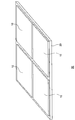
- FIG. 1 is a perspective view of the hand foot cross monitor of the present embodiment.
- the hand foot cross monitor includes a base 1, a support 2 provided in the center of the upper surface of the base 1, and an upper unit 3 fixed to the upper end of the support 2.
- a foot measurement unit 4 is provided in front of the top surface of the base 1.
- the foot measurement unit 4 is provided with a pair of left and right radiation detection units 4a. Both feet of the person to be measured are placed on the pair of left and right radiation detection units 4a.
- the pair of left and right radiation detectors 4a detect radiation ( ⁇ rays, ⁇ rays, ⁇ rays) emitted from radioactive substances attached to the surfaces of the left and right feet of the measurement subject.
- a contact area 4b described later is provided between the pair of left and right radiation detection units 4a.
- the hinge 2a which makes it possible to bend the support
- a support portion 2 b that erects the support column 2 perpendicularly to the upper surface of the base 1 is provided at the lower end of the back surface of the support column 2.
- pillar 2 is comprised from the lower area
- the front connection portion of the lower region 2c is provided with a clasp 2e that is fitted to a protrusion 2h (see FIG. 6) provided on the front connection portion of the upper region 2d to fix the column 2 so that it cannot be bent.
- a hinge 2f (see FIG. 6) that allows the upper region 2d to be bent toward the back surface of the lower region 2c is provided at the back surface connecting portions of both the lower region 2c and the upper region 2d. Further, a spacer 2g described later is provided below the clasp 2e at the front connection portion of the lower region 2c.
- the upper unit 3 has a board shape that is at least thicker than the palm of the person to be measured.
- a display unit 5 that displays the radiation measurement result of each part of the measurement subject and a buzzer 6 that issues an alarm based on the radiation measurement result are provided.
- the upper unit 3 is provided with a pair of left and right hand measuring units 7 so as to sandwich the display unit 5.
- the hand measurement section 7 is provided with a hand insertion section 7a into which the measurement subject's hand is inserted, and a pair of radiation detection sections 7b are provided on opposite side surfaces of the hand insertion section 7a.
- the pair of radiation detectors 7b detect radiation ( ⁇ rays, ⁇ rays, ⁇ rays) emitted from radioactive substances attached to the palm of the subject and the back of the hand inserted into the hand insertion portion 7a.
- a hook 3a capable of hanging the clothing measuring unit 8 is provided on one side surface of the upper unit 3.
- the clothes measuring unit 8 has a substantially rectangular parallelepiped shape.
- a handle 8a for the person to be measured to hold the clothes measuring unit 8 is provided on one side of the clothing measuring unit 8, and a radiation detecting unit 8b is provided on the other side facing the clothing measuring unit 8.
- the radiation detection unit 8b detects radiation ( ⁇ rays, ⁇ rays, ⁇ rays) emitted from a radioactive substance attached to the surface of the measurement subject's clothes.
- the radiation detection units 4a, 7b, and 8b of such a hand foot cross monitor are semiconductor type radiation detection devices, and the radiation detection elements 10 made of semiconductor are densely arranged in two dimensions.
- the number of the radiation detection elements 10 arranged in the radiation detection units 4a, 7b, and 8b can be changed as appropriate.
- the radiation detection units 4a, 7b, and 8b may be a combination of a plurality of radiation detection units 50 as shown in FIG. In the radiation detection unit 50 shown in FIG. 2, four radiation detection elements 10 are fixed on one substrate 20.
- FIG. 3 is a perspective view of a radiation detection element constituting the radiation detection unit of the hand foot cross monitor according to the present embodiment.
- the radiation detection element 10 has a flat plate shape of 25 mm square.
- the sectional shape of the radiation detection element 10 taken along line A in FIG. 3 will be described with reference to FIG.
- the radiation detection element 10 includes a detection unit 11, a circuit board side electrode 12, a detection surface side electrode 13, a silicon nitride film 14 as a surface protection layer, and a silicone resin as a side surface protection layer.
- Layer 15 is mainly provided.
- the detection unit 11 of the radiation detection element 10 includes an N-type semiconductor substrate, here an N-type silicon substrate 111.
- a P ⁇ layer 114 is provided on one main surface of the N-type silicon substrate 111.
- the P ⁇ layer 114 is a layer having a low impurity concentration, that is, a high electrical resistance value, and is a layer for making ohmic contact with the circuit board side electrode 12 described later.
- the P ⁇ layer 114 is formed by diffusing elements such as boron into the N-type silicon substrate.
- a P layer 112 is formed on the other main surface of the N-type silicon substrate 111.
- the depth of the P layer 112 is about several tens of ⁇ m.
- the P layer 112 is formed as follows, for example. First, a silicon oxide film is deposited on the other main surface of the N-type silicon substrate 111 by a method such as sputtering, and the silicon oxide film is patterned so as to open a portion corresponding to a region where the P layer 112 is formed. Using the silicon oxide film as a mask, an element such as boron is diffused into the exposed N-type silicon substrate, and then the silicon oxide film is removed.
- a P + layer 113 is provided outside the N-type silicon substrate 111 exposed outside the P layer 112.
- the P + layer 113 is a layer having a high impurity concentration, that is, a low electrical resistance value.
- the P + layer 113 is grounded and has the same potential as the circuit board side electrode 12.
- a positive electric field is also formed in the vicinity of the P + layer 113, and electrons move. That is, since no current flows in this region, the depletion layer 117 can be prevented from spreading to the side surface. The presence of such a P + layer 113 can reduce leakage current.
- the P + layer 113 is formed by depositing a silicon oxide film on the other main surface of the N-type silicon substrate 111 by a method such as sputtering, and opening a portion corresponding to the formation region of the P + layer 113. Then, using the remaining silicon oxide film as a mask, an element such as boron is diffused into the exposed N-type silicon substrate 111, and then the silicon oxide film is removed.
- a silicon oxide film 115 is formed on the N-type silicon substrate 111 exposed outside the P layer 112. This silicon oxide film 115 prevents the polarity reversal from occurring in the exposed region of the N-type silicon substrate 111 and the leakage current from flowing in the direction along the substrate surface.
- the silicon oxide film 115 is deposited on the other main surface of the N-type silicon substrate 111 by a method such as sputtering, and the silicon oxide film 115 is patterned so as to remain on the exposed N-type silicon substrate. To form.
- the upper layer of the silicon oxide film 115 is a gettering layer 116.
- the gettering layer 116 captures and removes impurities contained in the silicon oxide film layer.
- the gettering layer 116 is formed by doping the silicon oxide film 115 with phosphorus and modifying the surface.
- a circuit board side electrode 12 is formed on the P ⁇ layer 114 of the N-type silicon substrate 111.
- the circuit board side electrode 12 is formed by depositing an electrode material on the P ⁇ layer 114 by sputtering or the like.
- the detection surface side electrode 13 is formed on the P layer 112 of the N-type silicon substrate.
- the detection surface side electrode 13 is formed by depositing an electrode material on the P layer 112 by sputtering or the like and patterning the electrode material so as to remain on the P layer 112.
- the detection surface side electrode 13 is preferably a conductive film that also serves as a light shielding film such as aluminum.
- a silicon nitride film 14 is formed as a surface-side protective layer so as to cover the surface.
- the silicon nitride film 14 is for extending the life of the radiation detection element 10 while maintaining the radiation detection performance.
- the thickness of the silicon nitride film 14 is preferably 0.5 ⁇ m to 1.5 ⁇ m in consideration of an increase in leakage current due to stress generation due to high hardness.
- the silicon nitride film 14 is formed by depositing silicon nitride on the other main surface of the N-type silicon substrate 111 by sputtering or the like.
- the silicon nitride film is a protective film having excellent moisture resistance as can be seen from an environmental test (accelerated test) described later.
- a paraxylylene-based organic film is used as a protective film having the same environmental performance. A thin film can also be used.
- a silicone resin layer 15 is provided as a side surface side protective layer in the side surface region excluding the upper surface (sensitive region) of the detection unit 11.
- the silicone resin layer 15 is also for extending the life of the radiation detection element 10 while maintaining the radiation detection performance.
- the silicone resin layer 15 is formed by applying a silicone resin to the side surface of the detection unit 11 and drying it.
- the P layer 112 may be an amorphous silicon layer. That is, amorphous silicon is formed on the N-type silicon substrate 111 by a CVD (Chemical Vapor Deposition) method through a mask in which a P-layer formation region is opened, and an amorphous silicon P layer is formed on the N-type silicon substrate 111. May be.
- CVD Chemical Vapor Deposition
- the beta ray radiation detecting element counts (captures) not only beta rays but also light, it has excellent environmental performance (moisture permeability) and has light-shielding properties.
- An organic film such as polyimide that can be prevented is also used.
- the protective film has a sufficient moisture-proof function because the thickness of the protective film can be ensured only up to about 6 ⁇ m. For this reason, it is necessary to provide sufficient moisture resistance to the protective film formed on the radiation detection element. Therefore, the entire surface including the electrode portion is covered with a silicon nitride film (or paraxylylene-based organic thin film) so that the protective film has sufficient moisture resistance.
- the light shielding property can be realized by using a conductive film that also serves as a light shielding film such as aluminum for the detection surface side electrode 13.
- FIG. 5 is a circuit block diagram of the radiation detection unit of the hand foot cross monitor of the present embodiment.
- a signal processing unit 30 is provided for each radiation detection element 10, and each signal processing unit 30 is connected to the MPU 40.
- Each signal processing unit 30 amplifies the signal emitted from the radiation detection element 10.
- MPU40 detects the signal amplified by each signal processing part 30, counts a detection signal, and calculates a radiation dose based on a count result. When the calculated radiation dose exceeds a predetermined value, the MPU 40 controls the buzzer 6 of the hand foot cross monitor so as to issue an alarm, and displays so as to display a warning of a contaminated site where the calculated radiation dose exceeds the predetermined value.
- the unit 5 is controlled. Note that the MPU 40 can specify the contamination site in more detail by controlling the count range of the detection signal from the radiation detection element 10.
- a person to be measured places both feet on a pair of left and right radiation detection units 4a provided in the foot measurement unit 4 in the hand foot cross monitor shown in FIG. 1 in order to detect radioactive substances attached to the surfaces of the hands and feet.
- a hand / foot measurement start button (not shown) is pressed, and both hands are inserted into the hand insertion part 7 a provided in the pair of hand measurement parts 7.
- the person to be measured holds the handle 8a of the clothing measuring unit 8 and presses a clothing measurement start button (not shown) in order to detect radioactive substances adhering to the surface of the clothing after hand / foot inspection.
- the radiation detection unit 8b is brought close to its own clothes.
- a voltage is applied to the radiation detection elements 10 arranged in the radiation detection units 4a, 7b, and 8b.
- the radiation detection element 10 shown in FIG. 4 when a negative voltage is applied to the P layer 112 and a positive voltage is applied to the N-type silicon substrate 111, that is, when a reverse bias is applied to the pn junction, A depletion layer 117 is formed.
- This depletion layer 117 is a region having a high specific resistance and a high electric field strength. Therefore, when radiation such as ⁇ rays enters the radiation detection element 10 in this state, it is ionized in the depletion layer 117 and is effectively collected as secondary electrons. The effectively collected secondary electrons become a pulsed current signal, and radiation can be detected by detecting this pulsed current signal.
- a silicon nitride film 14 is formed so as to cover the other main surface of the radiation detection element 10, that is, the N-type silicon substrate 111, and a silicone resin layer is formed at least in a region including the side surface of the detection unit 11.
- the radiation detection performance can be maintained over a long period of time. Specifically, when an accelerated test was performed by leaving the radiation detection element 10 having the configuration shown in FIG. 4 at 85 ° C. and 85% RH in a state where a reverse bias of 150 V was applied, a target leakage current value of 150 nA ( Room temperature) or less (measured value of 100 nA or less) was confirmed.
- the bias voltage necessary for ionizing the radiation and forming the depletion layer 117 sufficient to effectively collect the secondary electrons can be reduced.
- a bias voltage of 200 V is required to form a sufficient depletion layer 117.
- the sufficient depletion layer 117 can be formed with a bias voltage of 100 V or less. For this reason, the structure shown in FIG. 4 is an advantageous structure from the viewpoint of withstand voltage.
- the semiconductor detection device capable of maintaining the radiation detection performance for a long period of time is used as the radiation detection sensor, and a small and lightweight hand foot cross monitor is provided. can do.
- FIG. 6 is a diagram illustrating a state in which the column of the hand foot cross monitor according to the present embodiment is bent.
- FIG. 6 the clasp 2e fitted to the protrusion 2h of the upper region 2d of the support column 2 in FIG. 1 is removed, and the lower region 2c is bent toward the upper surface of the base 1 via the hinge 2a. .
- the length of the lower region 2c is limited so that the lower region 2c does not protrude from the base 1 when the lower region 2c is bent.
- a contact area 4 b is provided between the pair of radiation detection units 4 a of the foot measurement unit 4 of the base 1.
- the contact area 4b is for contacting the clasp 2e of the lower region 2c and the spacer 2g when the lower region 2c is bent toward the upper surface of the base 1.
- the upper region 2d from which the clasp 2e is removed is bent toward the back surface of the lower region 2c by the hinge 2f. Between the bent upper region 2d and lower region 2c, a support portion 2b provided at the lower end of the back surface of the lower region 2c is accommodated.
- the length of the upper region 2d is set such that the upper unit 3 fixed to the upper end of the upper region 2d protrudes from the base 1 when the upper region 2d is bent.
- a fixing portion 1 a for fixing the upper unit 3 protruding from the base 1 when the upper region 2 d is bent.
- the fixing unit 1a fixes the upper unit 3 by fitting a groove (not shown) provided on the back surface of the upper unit 3 into the fixing unit 1a.
- the hand foot cross monitor has been described in which the radiation detection element 10 detects the radiation emitted from the radioactive substance attached to the surface of the hand / foot of the subject (the person to be measured) and the surface of the clothes.
- the present invention can also be applied to a surface contamination monitor (for example, a laundry monitor or an article surface contamination monitor) in which the radiation detection element 10 detects radiation emitted from a radiation substance attached to the surface of the inspection object.
Landscapes
- Physics & Mathematics (AREA)
- Health & Medical Sciences (AREA)
- Spectroscopy & Molecular Physics (AREA)
- General Physics & Mathematics (AREA)
- High Energy & Nuclear Physics (AREA)
- Molecular Biology (AREA)
- Life Sciences & Earth Sciences (AREA)
- Engineering & Computer Science (AREA)
- Biomedical Technology (AREA)
- General Health & Medical Sciences (AREA)
- Medical Informatics (AREA)
- Nuclear Medicine, Radiotherapy & Molecular Imaging (AREA)
- Optics & Photonics (AREA)
- Measurement Of Radiation (AREA)
Abstract
Priority Applications (3)
| Application Number | Priority Date | Filing Date | Title |
|---|---|---|---|
| CN201080004037.1A CN102292654B (zh) | 2009-07-10 | 2010-07-09 | 表面污染监测器 |
| US13/144,053 US8822944B2 (en) | 2009-07-10 | 2010-07-09 | Surface contamination monitor |
| JP2011521970A JP5146604B2 (ja) | 2009-07-10 | 2010-07-09 | 表面汚染モニタ |
Applications Claiming Priority (2)
| Application Number | Priority Date | Filing Date | Title |
|---|---|---|---|
| JP2009-164092 | 2009-07-10 | ||
| JP2009164092 | 2009-07-10 |
Publications (1)
| Publication Number | Publication Date |
|---|---|
| WO2011004883A1 true WO2011004883A1 (fr) | 2011-01-13 |
Family
ID=43429308
Family Applications (2)
| Application Number | Title | Priority Date | Filing Date |
|---|---|---|---|
| PCT/JP2010/061664 Ceased WO2011004883A1 (fr) | 2009-07-10 | 2010-07-09 | Moniteur de contamination de surface |
| PCT/JP2010/061665 Ceased WO2011004884A1 (fr) | 2009-07-10 | 2010-07-09 | Élément de détection de rayonnement et moniteur de contamination de surface |
Family Applications After (1)
| Application Number | Title | Priority Date | Filing Date |
|---|---|---|---|
| PCT/JP2010/061665 Ceased WO2011004884A1 (fr) | 2009-07-10 | 2010-07-09 | Élément de détection de rayonnement et moniteur de contamination de surface |
Country Status (5)
| Country | Link |
|---|---|
| US (1) | US8822944B2 (fr) |
| JP (1) | JP5146604B2 (fr) |
| KR (1) | KR20120049165A (fr) |
| CN (1) | CN102292654B (fr) |
| WO (2) | WO2011004883A1 (fr) |
Cited By (2)
| Publication number | Priority date | Publication date | Assignee | Title |
|---|---|---|---|---|
| CN114200502A (zh) * | 2021-12-13 | 2022-03-18 | 中国核动力研究设计院 | 一种核级树脂综合应用性能测试装置 |
| CN114924304A (zh) * | 2022-05-13 | 2022-08-19 | 上海新漫传感科技有限公司 | 一种移动式智能手足表污监测仪 |
Families Citing this family (14)
| Publication number | Priority date | Publication date | Assignee | Title |
|---|---|---|---|---|
| JP4877428B2 (ja) * | 2009-07-03 | 2012-02-15 | 富士電機株式会社 | 退出モニタ |
| CN102998692B (zh) * | 2011-09-16 | 2015-06-03 | 中国人民解放军63973部队 | 手足污染检测仪 |
| US8748838B2 (en) * | 2011-11-16 | 2014-06-10 | Canberra Industries, Inc. | Body self-shielding background compensation for contamination monitors based on anthropometrics |
| US9040932B2 (en) * | 2011-11-16 | 2015-05-26 | Canberra Industries, Inc. | Surface contamination monitoring system and method |
| USD694131S1 (en) * | 2012-06-01 | 2013-11-26 | Fuji Electric Co., Ltd. | Radiation monitor |
| CN104865592B (zh) * | 2014-02-26 | 2017-10-27 | 中国人民解放军63973部队 | 一种α、β射线探测器 |
| TWI600125B (zh) * | 2015-05-01 | 2017-09-21 | 精材科技股份有限公司 | 晶片封裝體及其製造方法 |
| JP6638226B2 (ja) * | 2015-07-09 | 2020-01-29 | 富士電機株式会社 | 放射線モニタ及びハンドフットクロスモニタ |
| US10120100B2 (en) * | 2016-09-08 | 2018-11-06 | Rohde & Schwarz Gmbh & Co. Kg | Body scanner system and method for scanning a person |
| CN106405614A (zh) * | 2016-10-26 | 2017-02-15 | 绵阳市维博电子有限责任公司 | 简易手足污染检测仪 |
| CN108333619B (zh) * | 2018-01-31 | 2021-02-09 | 绵阳市维博电子有限责任公司 | 手污染检测仪及其使用方法 |
| CN109884683A (zh) * | 2019-03-12 | 2019-06-14 | 苏州瑞派宁科技有限公司 | 一种辐射探测装置 |
| CN112462407B (zh) * | 2020-11-10 | 2022-04-15 | 中国核动力研究设计院 | 一种燃料板表面污染定位检测装置和系统 |
| CN219478249U (zh) * | 2022-11-29 | 2023-08-04 | 上海新漫传感科技有限公司 | 一种壁挂式手污染监测仪探头防护装置 |
Citations (9)
| Publication number | Priority date | Publication date | Assignee | Title |
|---|---|---|---|---|
| JPH07122776A (ja) * | 1993-08-31 | 1995-05-12 | Seiko Instr Inc | 光・放射線電気変換半導体装置およびその応用 |
| JPH114012A (ja) * | 1997-06-12 | 1999-01-06 | S I I R D Center:Kk | Pinフォトダイオード |
| JP2001228250A (ja) * | 2000-02-14 | 2001-08-24 | Ohyo Koken Kogyo Co Ltd | 簡易型体表面汚染モニタ |
| JP2001296365A (ja) * | 2000-04-13 | 2001-10-26 | Matsushita Electric Ind Co Ltd | X線撮影センサ |
| JP2001326376A (ja) * | 2000-05-12 | 2001-11-22 | Hamamatsu Photonics Kk | 半導体エネルギー検出素子 |
| JP2006339360A (ja) * | 2005-06-01 | 2006-12-14 | Hamamatsu Photonics Kk | エネルギー線検出素子 |
| JP2007114145A (ja) * | 2005-10-24 | 2007-05-10 | Mitsubishi Electric Corp | 形状可変型放射線検出器 |
| JP2008268038A (ja) * | 2007-04-23 | 2008-11-06 | Hitachi Ltd | 半導体放射線検出器及び産業用x線ct装置 |
| JP2009139346A (ja) * | 2007-12-11 | 2009-06-25 | Fuji Electric Systems Co Ltd | 放射線検出センサおよび放射線検出センサユニット |
Family Cites Families (7)
| Publication number | Priority date | Publication date | Assignee | Title |
|---|---|---|---|---|
| JPS63193088A (ja) | 1987-02-06 | 1988-08-10 | Hitachi Ltd | 半導体放射線検出器 |
| US5041728A (en) * | 1989-12-11 | 1991-08-20 | Rochester Gas And Electric Corpration | Portable personnel monitor which is collapsible for transporting and storage |
| JP3456068B2 (ja) * | 1995-09-21 | 2003-10-14 | 富士電機株式会社 | 体表面モニタ |
| JP3827847B2 (ja) * | 1998-01-30 | 2006-09-27 | 株式会社東芝 | ランドリモニタ装置 |
| JP2001274450A (ja) | 2000-03-23 | 2001-10-05 | Fuji Electric Co Ltd | β線検出器 |
| JP2003167059A (ja) * | 2001-11-29 | 2003-06-13 | Fuji Electric Co Ltd | ハンドフットクローズモニタ |
| CN2715170Y (zh) * | 2004-04-07 | 2005-08-03 | 中国人民解放军第二炮兵防护防疫环境监测队 | 车载式全身放射性污染测量仪 |
-
2010
- 2010-07-09 WO PCT/JP2010/061664 patent/WO2011004883A1/fr not_active Ceased
- 2010-07-09 CN CN201080004037.1A patent/CN102292654B/zh active Active
- 2010-07-09 KR KR1020117014305A patent/KR20120049165A/ko not_active Abandoned
- 2010-07-09 US US13/144,053 patent/US8822944B2/en active Active
- 2010-07-09 JP JP2011521970A patent/JP5146604B2/ja active Active
- 2010-07-09 WO PCT/JP2010/061665 patent/WO2011004884A1/fr not_active Ceased
Patent Citations (9)
| Publication number | Priority date | Publication date | Assignee | Title |
|---|---|---|---|---|
| JPH07122776A (ja) * | 1993-08-31 | 1995-05-12 | Seiko Instr Inc | 光・放射線電気変換半導体装置およびその応用 |
| JPH114012A (ja) * | 1997-06-12 | 1999-01-06 | S I I R D Center:Kk | Pinフォトダイオード |
| JP2001228250A (ja) * | 2000-02-14 | 2001-08-24 | Ohyo Koken Kogyo Co Ltd | 簡易型体表面汚染モニタ |
| JP2001296365A (ja) * | 2000-04-13 | 2001-10-26 | Matsushita Electric Ind Co Ltd | X線撮影センサ |
| JP2001326376A (ja) * | 2000-05-12 | 2001-11-22 | Hamamatsu Photonics Kk | 半導体エネルギー検出素子 |
| JP2006339360A (ja) * | 2005-06-01 | 2006-12-14 | Hamamatsu Photonics Kk | エネルギー線検出素子 |
| JP2007114145A (ja) * | 2005-10-24 | 2007-05-10 | Mitsubishi Electric Corp | 形状可変型放射線検出器 |
| JP2008268038A (ja) * | 2007-04-23 | 2008-11-06 | Hitachi Ltd | 半導体放射線検出器及び産業用x線ct装置 |
| JP2009139346A (ja) * | 2007-12-11 | 2009-06-25 | Fuji Electric Systems Co Ltd | 放射線検出センサおよび放射線検出センサユニット |
Cited By (2)
| Publication number | Priority date | Publication date | Assignee | Title |
|---|---|---|---|---|
| CN114200502A (zh) * | 2021-12-13 | 2022-03-18 | 中国核动力研究设计院 | 一种核级树脂综合应用性能测试装置 |
| CN114924304A (zh) * | 2022-05-13 | 2022-08-19 | 上海新漫传感科技有限公司 | 一种移动式智能手足表污监测仪 |
Also Published As
| Publication number | Publication date |
|---|---|
| JP5146604B2 (ja) | 2013-02-20 |
| WO2011004884A1 (fr) | 2011-01-13 |
| CN102292654B (zh) | 2013-12-25 |
| US8822944B2 (en) | 2014-09-02 |
| CN102292654A (zh) | 2011-12-21 |
| KR20120049165A (ko) | 2012-05-16 |
| US20120161265A1 (en) | 2012-06-28 |
| JPWO2011004883A1 (ja) | 2012-12-20 |
Similar Documents
| Publication | Publication Date | Title |
|---|---|---|
| JP5146604B2 (ja) | 表面汚染モニタ | |
| CN107257932B (zh) | 利用双探针结构的电离箱以及差分放大器的阿尔法粒子检测装置 | |
| JP3980450B2 (ja) | 放射線検出器および放射線検出方法 | |
| Uher et al. | Characterization of 3D thermal neutron semiconductor detectors | |
| US20150279642A1 (en) | Apparatus for sensing ionic current | |
| WO2015026262A1 (fr) | Capteur de rayonnement ionisant | |
| US9831375B2 (en) | Solid state radiation detector with enhanced gamma radiation sensitivity | |
| KR101226735B1 (ko) | 알파 방사선을 방출하는 기체의 농도 계측기 및 계측 방법 | |
| Raval et al. | Copper (II) phthalocyanine based organic electronic devices for ionizing radiation dosimetry applications | |
| JP2009139346A (ja) | 放射線検出センサおよび放射線検出センサユニット | |
| US8536885B2 (en) | Method and device for determining ionizing radiation | |
| US11287539B2 (en) | Apparatus for sensing radiation | |
| CN104620387B (zh) | 光子计数半导体探测器 | |
| EP3032281A1 (fr) | Détecteur de dérive à semi-conducteur pour détecter un rayonnement | |
| RU2484554C1 (ru) | Способ регистрации ионизирующих излучений | |
| KR20140022183A (ko) | SiPM을 이용한 전자식 방사선 개인선량계 | |
| WO2015102517A1 (fr) | Capteur matriciel de rayonnement ionisant | |
| US8927938B2 (en) | Alpha-particle detection device | |
| Abbaszadeh | Indirect conversion amorphous selenium photodetectors for medical imaging applications | |
| KR20150073239A (ko) | 이종 방사선 측정 센서 및 그 제조 방법 | |
| US20110233405A1 (en) | Radiation detector | |
| Srivastava et al. | Characterization of pin diode silicon radiation detector | |
| KR100423536B1 (ko) | 가돌리늄막을 가진 pMOSFET센서와 pMOSFET센서 및 감산기를 사용하여 감마선/열중성자를 동시에 검출하는 실시간 전자적 선량계 및 그 검출방법 | |
| JP2007114145A (ja) | 形状可変型放射線検出器 | |
| JP2000266855A (ja) | 放射線検出器 |
Legal Events
| Date | Code | Title | Description |
|---|---|---|---|
| WWE | Wipo information: entry into national phase |
Ref document number: 201080004037.1 Country of ref document: CN |
|
| 121 | Ep: the epo has been informed by wipo that ep was designated in this application |
Ref document number: 10797194 Country of ref document: EP Kind code of ref document: A1 |
|
| ENP | Entry into the national phase |
Ref document number: 2011521970 Country of ref document: JP Kind code of ref document: A |
|
| ENP | Entry into the national phase |
Ref document number: 20117014305 Country of ref document: KR Kind code of ref document: A |
|
| NENP | Non-entry into the national phase |
Ref country code: DE |
|
| WWE | Wipo information: entry into national phase |
Ref document number: 13144053 Country of ref document: US |
|
| 122 | Ep: pct application non-entry in european phase |
Ref document number: 10797194 Country of ref document: EP Kind code of ref document: A1 |