WO2011007597A1 - Dispositif de distribution d'ions - Google Patents
Dispositif de distribution d'ions Download PDFInfo
- Publication number
- WO2011007597A1 WO2011007597A1 PCT/JP2010/053619 JP2010053619W WO2011007597A1 WO 2011007597 A1 WO2011007597 A1 WO 2011007597A1 JP 2010053619 W JP2010053619 W JP 2010053619W WO 2011007597 A1 WO2011007597 A1 WO 2011007597A1
- Authority
- WO
- WIPO (PCT)
- Prior art keywords
- ion
- main body
- front panel
- electrode
- delivery device
- Prior art date
- Legal status (The legal status is an assumption and is not a legal conclusion. Google has not performed a legal analysis and makes no representation as to the accuracy of the status listed.)
- Ceased
Links
Images




Classifications
-
- H—ELECTRICITY
- H01—ELECTRIC ELEMENTS
- H01T—SPARK GAPS; OVERVOLTAGE ARRESTERS USING SPARK GAPS; SPARKING PLUGS; CORONA DEVICES; GENERATING IONS TO BE INTRODUCED INTO NON-ENCLOSED GASES
- H01T23/00—Apparatus for generating ions to be introduced into non-enclosed gases, e.g. into the atmosphere
-
- A—HUMAN NECESSITIES
- A61—MEDICAL OR VETERINARY SCIENCE; HYGIENE
- A61L—METHODS OR APPARATUS FOR STERILISING MATERIALS OR OBJECTS IN GENERAL; DISINFECTION, STERILISATION OR DEODORISATION OF AIR; CHEMICAL ASPECTS OF BANDAGES, DRESSINGS, ABSORBENT PADS OR SURGICAL ARTICLES; MATERIALS FOR BANDAGES, DRESSINGS, ABSORBENT PADS OR SURGICAL ARTICLES
- A61L9/00—Disinfection, sterilisation or deodorisation of air
- A61L9/16—Disinfection, sterilisation or deodorisation of air using physical phenomena
- A61L9/22—Ionisation
-
- F—MECHANICAL ENGINEERING; LIGHTING; HEATING; WEAPONS; BLASTING
- F24—HEATING; RANGES; VENTILATING
- F24F—AIR-CONDITIONING; AIR-HUMIDIFICATION; VENTILATION; USE OF AIR CURRENTS FOR SCREENING
- F24F8/00—Treatment, e.g. purification, of air supplied to human living or working spaces otherwise than by heating, cooling, humidifying or drying
- F24F8/30—Treatment, e.g. purification, of air supplied to human living or working spaces otherwise than by heating, cooling, humidifying or drying by ionisation
Definitions
- the present invention relates to an ion delivery device for delivering ions into a living room.
- Patent Document 1 A conventional ion delivery device is disclosed in Patent Document 1.
- This ion delivery device has a main body part arranged on a ceiling wall of a living room, and a suction port and an air outlet open on the lower surface of the main body part facing the living room.
- a blower passage that connects the suction port and the blower outlet is provided in the main body, and a blower fan is disposed in the blower passage.
- an ion generator that generates ions facing the air passage is provided above the main body. The ion generator applies ions to the electrodes to generate ions by discharge.
- the air in the room flows into the air passage from the suction port. Ions generated by the ion generator are mixed in the air flowing through the air passage, and air containing ions is sent out from the outlet. Thereby, negative ions can be sent into the living room to reduce the active oxygen in the human body.
- An ion generator that generates ions is deteriorated by long-term use because a high voltage is applied. At this time, since the ion generator is disposed above the main body, it is necessary to remove the main body from the ceiling together with the ion generator when replacing the deteriorated ion generator. For this reason, there is a problem that maintenance of the ion delivery device becomes difficult.
- an ion delivery device in which an ion generator is detachable from an opening surface of a main body.
- This ion delivery device includes a front panel having a suction port and a blowout port, and the front panel is fixed to the front surface of the main body by screwing or the like at opposite ends.
- a holding part for holding an ion generator connected by a lead wire is provided in the main body part.
- the holding portion has an engaging claw, and the engaging claw engages with the lower surface of the ion generating device inserted into the holding portion to prevent the ion generating device from falling.
- the front panel covering the main body is removed, and the operator removes the engaging claw from the lower surface of the ion generator while holding the ion generator with fingers. Thereby, an ion generator falls in an operator's hand, a lead wire can be removed and an ion generator can be replaced
- An object of the present invention is to provide an ion delivery device that can improve the workability at the time of replacement of an ion generator. It is another object of the present invention to provide an ion delivery device that can improve safety when replacing an ion generator.
- the present invention is provided in a main body part that is attached to a ceiling wall of a living room, a front panel that covers a lower surface of the main body part and that has an inlet and an outlet, and is provided in the main body part.
- a blower passage that communicates the suction port with the blowout port, a blower fan that is disposed in the blower passage, and an ion generator that includes an electrode unit that generates ions.
- An operation button provided at one end of the front panel so as to be horizontally movable and biased in a direction protruding from the front panel and having a claw protruding upward, and a fulcrum attached to the other end of the front panel
- a torsion spring having a locking portion protruding outward at a tip extending in a V shape from the portion; a first engagement member provided on the main body portion for engaging the claw portion that moves horizontally; and And a second engagement member that is inserted through the tip of the torsion spring and engages with the vicinity of the fulcrum portion by the elasticity of the torsion spring.
- the front panel having the suction port and the air outlet is arranged on the front surface of the main body, and when the blower fan is driven, the air in the room flows into the air passage in the main body from the suction port. Ions generated at the electrode part are mixed with the air flowing through the air passage, and air containing the ions is sent out from the outlet.
- the front panel is attached with claw portions and torsion springs that are respectively engaged with first and second engaging portions provided on the main body portion, arranged at both ends.
- the claw portion is provided on an operation button that is urged in a direction protruding from the front panel, and is slidably engaged with the first engagement portion by the urging.
- the torsion spring extends in a V shape from a fulcrum portion attached to the front panel.
- the torsion spring expands elastically above the second engagement portion and engages with the second engagement portion.
- the present invention is also characterized in that, in the ion delivery device having the above-described configuration, chamfering is performed on the upper end of the peripheral surface of the front panel. According to this configuration, a shadow is formed around the front panel by chamfering, and it is difficult to see the gap between the front panel and the ceiling wall, so that the aesthetics of the ion delivery device can be improved.
- the present invention is characterized in that, in the ion delivery device having the above-described configuration, a sliding contact surface that comes into sliding contact with the first engagement member of the claw portion is an inclined surface. According to this configuration, the slidable contact surface formed by the inclined surface of the claw portion urges the first engagement member, and the front panel is pulled upward. Thereby, generation
- the present invention provides a main body portion that is installed in a ceiling wall of a living room, a front panel that covers a lower surface of the main body portion and opens a suction port and an outlet, and the suction port provided in the main body portion.
- a blower passage communicating with the blower outlet, a blower fan arranged in the blower passage, an ion generator having an electrode part having an electrode for generating ions in front, and the electrode part in the blower passage And holding the ion generator detachably so that the air generated in the electrode unit is mixed with the air in the room flowing into the air passage from the suction port by driving the air blowing fan.
- the holding portion slides on the back surface portion supporting the back surface of the ion generating device and the front surface of the ion generating device inserted along the back surface portion and elastically deforms in a direction perpendicular to the insertion direction.
- An engaging claw that engages with a lower surface of the ion generating device, and a groove portion that engages the engaging claw with a shallower engaging depth than the lower surface of the ion generating device when the ion generating device is attached or detached. It is provided in the front of the generator.
- the air in the room flows from the suction port into the blower passage in the main body. Ions generated at the electrode part are mixed with the air flowing through the air passage, and air containing the ions is sent out from the outlet.
- the ion generator is inserted along the back surface portion of the holding portion provided on the main body portion on the back surface side. At this time, the elastically deformed engaging claw slides on the front side of the ion generating device, and the engaging claw engages with the lower surface of the ion generating device and is held by the holding portion. When the ion generator is detached, the engaging claw is detached from the lower surface of the ion generator while holding the ion generator with fingers.
- the engaging claw slides in front of the ion generator and engages with the groove. At this time, since the engaging claw has a shallower engagement depth with the groove than when engaged with the lower surface of the ion generator, the ion generator can be pulled out and removed. In addition, even if the user forgets to hold the ion generating device with fingers, the engaging claw engages with the groove portion to prevent the ion generating device from falling.
- the ion generation device in the ion delivery device configured as described above, includes an ion generation element provided with a terminal that exposes the electrode portion and is electrically connected to the electrode portion, and covers the ion generation element and the electrode.
- a cover that opens a hole facing the portion, and a power that is connected to the terminal via a lead wire and held by the cover, and is provided to the main body when the ion generator is attached to the holding portion And a connector inserted into the supply terminal, and the connector is loosely attached to the cover.
- the connector integrated with the cover is inserted into the terminal part, and power is supplied to the electrode part of the ion generating element. Ions generated from the electrode part are discharged to the air passage through the hole of the cover that covers the ion generating element.
- the connector is loosely attached to the cover, so that the connector can be reliably inserted into the terminal portion even when the ion generator is tilted when inserted into the holding portion.
- the electrode portion includes a needle-like discharge electrode and an annular induction electrode disposed around the discharge electrode, and a periphery of the hole portion is the induction electrode. It is characterized by being arranged inside. According to this configuration, ions are generated between the needle-like discharge electrode and the annular induction electrode, and are discharged to the air passage through the hole.
- the hole portion is formed smaller than the induction electrode with the peripheral edge inside the induction electrode, and contact between the discharge electrode and the induction electrode and the finger is prevented.
- the ion generator has a guide groove extending in the insertion direction on the back surface, and the holding portion is fitted in the guide groove to guide the ion generator. It has a protrusion. According to this configuration, the guide protrusion provided on the back surface of the holding portion is fitted into the guide groove provided on the back surface of the ion generator, and the ion generator is inserted along the back surface.
- the main body is partitioned and elastically deformed, and the grill is engaged with the main body.
- the front panel opens the suction port at the center.
- the air outlet is provided around the suction port, and a plurality of branch passages for branching the air passage are formed in the peripheral portion of the main body portion by the grill, and the clip is provided at two opposing positions between the branch passages. It is provided that the engagement with the main body is released by tilting in the direction in which the end on the front panel side approaches.
- a ventilation passage having a plurality of branch passages is formed in the main body portion by the grill.
- the air that has flowed into the air passage from the suction port in the central portion is branched into each branch passage, and is sent out from the peripheral air outlet including ions.
- the grill is inserted from the opening surface of the main body, and is engaged by elastically deforming clips provided at two opposing positions between the branch passages. When the lower end of the clip is gripped with fingers so as to approach each other, the engagement between the clip and the main body is released, and the grill can be removed.
- the electrode part has a positive ion part that generates positive ions and a negative ion part that generates negative ions, and the positive ion part and the negative ions are separated from each other. It is characterized in that the portion is arranged facing the different branch passage. According to this configuration, negative ions are sent out through one branch passage partitioned by the grill, and positive ions are sent out through the other branch passage.
- the front panel has a claw portion and is provided with an operation button that horizontally moves at one end, and a torsion spring is loosely attached to the other end, and engages with the claw portion and the torsion spring, respectively. Since the engaging member is provided in the main body, the front panel can be easily opened by pressing the operation button. Further, when the front panel is opened, it can be separated from the opening surface of the main body according to the length of the torsion spring. Thereby, workability at the time of replacement
- the ion generator is configured such that the holding portion provided in the main body supports the back surface of the ion generator and slides on the front of the ion generator and elastically deforms in a direction perpendicular to the insertion direction. Since the groove for engaging with the engaging claw is provided on the front surface of the ion generating device, the engaging claw is attached to the lower surface of the ion generating device when the ion generating device is detached. When it is detached from the engaging claw, the engaging claw engages with the groove. For this reason, even if it forgets to hold
- Side surface sectional drawing which shows the attachment state of the ion sending apparatus of embodiment of this invention.
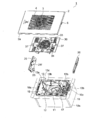
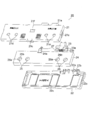
- the exploded perspective view seen from the front side of the ion sending device of the embodiment of the present invention The exploded perspective view seen from the back side of the ion sending device of the embodiment of the present invention
- Side surface sectional drawing which shows the state which opened the front panel of the ion sending apparatus of embodiment of this invention
- FIG. 1 is a perspective view showing an attachment state of an ion delivery device 1 according to an embodiment.
- the ion delivery apparatus 1 is attached to the ceiling wall A of a living room, and the front panel 2 which covers the front surface is arranged facing the living room.
- a suction port 3 is opened at the center of the front panel 2, and an air outlet 4 is provided around the suction port 3.
- FIG. 2 shows a side cross-sectional view of the ion delivery device 1.
- 3 and 4 show an exploded perspective view of the ion delivery device 1 seen from the front and an exploded perspective view seen from the back.
- the ion delivery device 1 has a main body portion 10 attached to the ceiling wall A, and an opening on the front surface of the main body portion 10 is covered with the front panel 2.
- an inner case 18 made of a resin molded product is attached inside a metal outer case 10a, and the opening side periphery of the outer case 10a is screwed to the ceiling wall A.
- An engagement member 10c (first engagement member) having an engagement hole 10b is attached to one end of the outer case 10a.
- An operation button 5 that moves horizontally is provided at one end of the front panel 2. The operation button 5 is urged in a direction protruding from the front panel 2. The rear end of the operation button 5 is provided with a claw portion 5a having an L-shaped cross section that protrudes upward and engages with the engagement member 10c through the engagement hole 10b.
- An engaging member 18a (second engaging member) integral with the inner case 18 having an insertion hole (not shown) is disposed at the other end of the outer case 10a.
- a fulcrum portion of a V-shaped torsion spring 6 is loosely attached to the other end of the front panel 2.
- a locking portion 6a that protrudes outward and is wound is formed.
- the front panel 2 inserts the torsion spring 6 with its tip closed into the insertion hole of the engagement member 18a, and the claw portion 5a of the operation button 5 engages with the engagement hole 10b of the engagement member 10c. Attached to. At this time, the torsion spring 6 spreads by an elastic force above the engaging member 18a, and the joined state between the front panel 2 and the main body 10 is maintained.
- the front panel 2 is held at the other end by the torsion spring 6 that is engaged at one end by the claw portion 5a of the operating portion 5 that moves horizontally and spreads above the engaging member 18a. Can be opened easily. Further, when the front panel 2 is opened, the front panel 2 can be separated from the opening surface of the main body 10 according to the length of the torsion spring 6. Thereby, the front panel 2 does not get in the way and the maintenance in the main-body part 10 can be performed easily.
- the claw portion 5a of the operation button 5 presses the front panel 2 upward to be inserted into the engagement hole 10b, and slides on the engagement member 10c to engage with the engagement hole 10b. Therefore, a vertical gap is formed between the upper surface of the front panel 2 and the ceiling wall A.
- a chamfer 2b is applied to the upper end of the peripheral surface 2a of the front panel 2.
- a shadow is formed on the ceiling wall A around the front panel 2 by the chamfer 2b, and the gap between the front panel 2 and the ceiling wall A can be made inconspicuous. Therefore, the aesthetics of the ion delivery device 1 can be improved.
- the inner case 18 forms an upper part of the air passage 12 that connects the suction port 3 and the air outlet 4, and holds the air fan 11 in the air passage 12.
- the blower fan 11 is an axial fan, and is arranged with the intake side facing the suction port 3.
- the air passage 12 is formed to extend from the exhaust side on the back surface of the air fan 11 to the outlet 4 through the periphery of the air fan 11.
- a grill 30 made of a resin molded product is disposed on the front surface of the inner case 18.
- the grill 30 is provided with openings 33 and 34 that face the inlet 3 and the outlet 4.
- a partition rib 30 a is projected from the upper surface of the grill 30.
- the lower part of the ventilation path 12 is formed of the partition rib 30a.
- the partition rib 30 a forms a plurality of branch passages 12 a that branch the blower passage 12 on the exhaust side of the blower fan 11 in the peripheral portion of the main body 10. In the present embodiment, four branch passages 12a are formed.
- clips 37 are protruded at two opposite positions between the branch passages 12 a outside the blower fan 11.
- the clip 37 is elastically deformed to engage with the protruding rib 17 protruding from the inner case 18, and the grill 30 is held by the main body 10.
- the tips of the clips 37 are tilted toward each other due to elasticity, the engagement between the clips 37 and the protruding ribs 17 is released.
- the tip of the clip 37 can be gripped with fingers and the grill 30 can be removed from the main body 10, and maintenance inside the main body 10 can be easily performed.
- the inner case 18 is provided with two holding portions 13 facing the air passage 12 and holding the two ion generators 20 facing each other.
- the holding unit 13 includes a back surface portion 13 a that supports the back surface of the ion generator 20 and an engaging claw 13 b that is disposed on the front side of the ion generator 20 and engages the bottom surface.
- the engaging claw 13b is elastically deformed in a direction perpendicular to the inserting direction and is engaged with the lower surface of the ion generating device 20. Thereby, the ion generator 20 is prevented from falling and is held.
- FIG. 6 shows an exploded perspective view of the ion generator 20.
- the ion generator 20 is formed by covering the front side and the back side of the ion generating element 24 with covers 21 and 22, respectively.
- the covers 21 and 22 are joined by engagement between an engagement hole 21c provided on the peripheral surface and an engagement protrusion 22c.
- the ion generating element 24 has electrode portions 25 and 26 for generating ions.
- the cover 21 on the front side is provided with holes 21d and 21e facing the electrode portions 25 and 26.
- the electrode portions 25 and 26 are provided apart from each other by a predetermined distance, and have needle-like discharge electrodes 25a and 26a and annular induction electrodes 25b and 26b arranged around the discharge electrodes 25a and 26a, respectively.
- a high positive voltage is applied to the discharge electrode 25a with respect to the induction electrode 25b, and a high negative voltage is applied to the discharge electrode 26a with respect to the induction electrode 26b.
- water in the air is mainly ionized between the discharge electrode 25a and the induction electrode 25b by corona discharge, and H + ions are generated.
- oxygen in the air is mainly ionized by corona discharge to generate O 2 ⁇ ions.
- H + ions generated by ionization from the electrode part 25 combine with moisture in the air to form positively clustered ions composed of H + (H 2 O) m.
- O 2 ⁇ ions generated by ionization from the electrode portion 26 are combined with moisture in the air to form cluster ions having a negative charge composed of O 2 ⁇ (H 2 O) n.
- m and n are arbitrary natural numbers. Accordingly, the electrode portion 25 constitutes a positive ion portion that generates positive ions, and the electrode portion 26 constitutes a negative ion portion that generates negative ions.
- H + (H 2 O) m and O 2 ⁇ (H 2 O) n agglomerate and surround the surface of airborne bacteria, odorous components, and stored bacteria.
- the active species [.OH] (hydroxyl radical) and H 2 O 2 (hydrogen peroxide) are agglomerated on the surface of the microorganism or the like by collision. Destroy airborne bacteria and odor components.
- m ′ and n ′ are arbitrary natural numbers. Accordingly, by generating positive ions mainly composed of H + (H 2 O) m and negative ions mainly composed of O 2 ⁇ (H 2 O) n and sending them out from the outlet 4, sterilization and odor removal in the room can be performed. It can be carried out.
- the inner edges of the holes 21d and 21e of the cover 21 are arranged on the inner side of the annular induction electrodes 25b and 26b, and the holes 21d and 21e are formed smaller than the induction electrodes 25b and 26b. This prevents the discharge electrodes 25a and 26a and the induction electrodes 25b and 26b from being in contact with fingers when the ion generator 20 is held. Therefore, it is possible to prevent the ion generating element 24 from being deteriorated due to foreign matters adhering to each electrode.
- the ion generating element 24 includes the discharge electrodes 25a and 26a and the annular induction electrodes 25b and 26b, but may have other configurations.
- the induction electrode may be omitted or a flat discharge electrode may be provided.
- the electrode part 25 (positive ion part) for generating positive ions and the electrode part 26 (negative ion part) for generating negative ions are respectively arranged facing different branch passages 12a. Thereby, the extinction by the collision with a positive ion and a negative ion can be reduced, and the reduction
- the electrode portions 25 of the two ion generators 20 are disposed opposite to each other on one diagonal of the main body 10, and the electrode portions 26 of the two ion generators 20 are disposed opposite to each other on the other diagonal.
- positive ions and negative ions can be dispersed and sent from the ion delivery device 1 to uniformly sterilize and deodorize the room.
- a terminal 24 a that is electrically connected to the electrode portions 25 and 26 is provided on the ion generating element 24.
- a connector 23 is connected to the terminal 24a via a lead wire 27 arranged in the covers 21 and 22.
- the connector 23 has columnar portions 23b projecting at two locations, and an annular groove 23a is formed on the peripheral surface of the columnar portion 23b.
- the support portions 21a and 22a of the covers 21 and 22 are formed with U-shaped cutout portions 21b and 22b (21b not shown) that fit into the groove portion 23a.
- the groove 23a of the connector 23 is sandwiched by the notches 21b and 22b of the support portions 21a and 22a, and the connector 23 is held by the covers 21 and 22 with the tip protruding. At this time, a radial gap is formed between the groove 23a and the notches 21b and 22b, and the connector 23 is loosely attached so that it can tilt between the front side and the back side.
- the connector 23 When the ion generator 20 is inserted along the back surface portion 13 a of the holding portion 13, the connector 23 is inserted into the power supply terminal portion 19 (see FIG. 2) provided in the main body portion 10. At this time, since the connector 23 is loosely attached to the covers 21 and 22, the connector 23 can be reliably inserted into the terminal portion 19 even when the ion generator 20 is tilted when inserted into the holding portion 13.
- a guide groove 22d (see FIG. 4) extending in the insertion direction to the holding portion 13 is formed in the rear cover 22.
- a guide protrusion 13c (see FIG. 3) that fits in the guide groove 22d is provided on the back surface portion 13a of the holding portion 13.
- a groove portion 21f is recessed in the surface of the cover 21 on the front side.
- the groove portion 21f is provided on a locus along which the engaging claw 13b (see FIG. 2) slides when the ion generator 20 is inserted into the holding portion 13.
- the engaging claw 13b slides on the cover 21 and engages with the groove 21f.
- the engaging claw 13b engages with the groove portion 21f with an engagement depth shallower than the lower surface of the ion generator 20.
- the inner peripheral surface of the groove 21f is formed as a flat or curved inclined surface.
- the air in the living room flows into the blower passage 12 from the suction port 3.
- the air flowing into the blower passage 12 branches into a plurality of branch passages 12 a on the exhaust side of the blower fan 11.
- Positive air and negative ions generated by the ion generator 20 are mixed in the air flowing through each branch passage 12a.
- the air containing an ion is sent out from the blower outlet 4 provided in the peripheral part of the front panel 2. FIG. Thereby, sterilization and deodorization of a living room can be performed.
- the user When the driving time of the ion generator 20 has passed a predetermined time, the user is notified by a display or the like on the remote controller so as to prompt the user to replace the ion generator 20.
- the operator presses the operation button 5 to release the engagement between the claw portion 5a and the engaging member 10c, and pulls out the front panel 2 that rotates with the torsion spring 6 as a fulcrum. Thereby, the latching
- both the clips 37 of the grill 30 are gripped with fingers, the engagement between the clips 37 and the protruding ribs 17 is released, and the grill 30 is removed.
- the operator removes the engaging claw 13b from the lower surface of the ion generator 20 while holding the ion generator 20 with fingers.
- the connector 23 is detached from the terminal portion 19, and the engaging claw 13a slides on the cover 21 on the front side of the ion generator 20 and engages with the groove portion 21f. Further, by pulling out the ion generator 20, the ion generator 20 is removed. Thereby, the ion generator 20 can be replaced
- the connector 23 and the terminal portion 19 held by the covers 21 and 22 The ion generator 20 is prevented from falling by the frictional force. Even if the connector 23 is detached from the terminal portion 19, the engaging claw 13b is engaged with the groove portion 21f, and the ion generator 20 is prevented from falling.
- the front panel 2 has the claw portion 5a and is provided with the operation button 5 that moves horizontally, and the torsion spring 6 is loosely attached to the other end, and is engaged with the claw portion 5a and the torsion spring 6, respectively. Since the engaging members 10 c and 18 a (first and second engaging members) to be combined are provided in the main body portion 10, the front panel 2 can be easily opened by pressing the operation button 5. Further, when the front panel 2 is opened, the front panel 2 can be separated from the opening surface of the main body 10 according to the length of the torsion spring 6. Thereby, the workability at the time of replacement
- chamfering 2b is applied to the upper end of the peripheral surface of the front panel 2, a shadow is formed around the front panel 2, making it difficult to see the gap between the front panel 2 and the ceiling wall A. Can be improved.
- the slidable contact surface slidably contacting the engaging member 10c of the claw portion 5a is inclined, the slidable contact surface formed by the inclined surface of the claw portion 5a urges the engaging member 10c and the front panel 2 is pulled upward. It is done. Thereby, generation
- the holding part 13 of the main body part 10 slides on the front surface of the ion generator 20 by supporting the back surface of the ion generator 20 and elastically deforms in a direction perpendicular to the insertion direction, and also the ion generator 20.
- the engaging claw 13b that engages the lower surface of the ion generating device 20 and the groove 21f that engages the engaging claw 13a is provided on the front surface of the ion generating device 20, so that the engaging claw 13a is removed when the ion generating device 20 is detached. Is detached from the lower surface of the ion generator 20, the engaging claw 13b engages with the groove 21f. For this reason, even if it forgets to hold
- the ion generating element 24 is covered with the covers 21 and 22 and the connector 23 connected to the terminal 24a via the lead wire 27 is loosely attached to the covers 22 and 22, the ion generating device 20 is held by the holding portion 13.
- the connector 23 can be reliably inserted into the terminal portion 19 even when tilted when inserted into the terminal portion 19. Therefore, the ion generator 20 can be easily replaced.
- peripheral edges of the holes 21d and 21e of the cover 21 are arranged on the inner side of the induction electrodes 25b and 26b, it is possible to prevent the discharge electrodes 25a and 26a and the induction electrodes 25b and 26b from being in contact with the fingers. Therefore, the performance deterioration of the ion generator 20 can be prevented.
- the guide groove 22d is formed on the back surface of the ion generator 20, and the guide projection 13c that fits the guide groove 22d and guides the ion generator 20 is provided on the holding portion 13, the back surface of the ion generator 20 is provided. The inclination in the direction along the portion 13a can be reduced and the mounting can be ensured.
- the grill 30 forming the plurality of branch passages 12a in the peripheral portion of the main body 10 is engaged and disengaged by the clips 37 provided at two opposing positions between the branch passages 12a. 30 can be easily attached and detached. Therefore, the ion generator 20 can be easily replaced.
- the electrode part 25 (positive ion part) that generates positive ions and the electrode part 26 (negative ion part) that generate negative ions are separated from each other, and the electrode parts 25 and 26 are arranged facing different branch passages 12a. Therefore, it is possible to reduce the disappearance due to the collision between the positive ions and the negative ions and to prevent the decrease of the ions sent from the outlet 4. Therefore, the sterilizing effect and deodorizing effect in the living room can be further improved.
- negative ions may be emitted from both electrode portions 25 and 26 of the ion generator 20.
- a relaxation effect, reduction of active oxygen in a human body, etc. can be aimed at.
- the present invention can be used for an ion sending device that sends ions into a living room.
Landscapes
- Health & Medical Sciences (AREA)
- Engineering & Computer Science (AREA)
- Veterinary Medicine (AREA)
- Animal Behavior & Ethology (AREA)
- General Health & Medical Sciences (AREA)
- Public Health (AREA)
- Life Sciences & Earth Sciences (AREA)
- Chemical & Material Sciences (AREA)
- Epidemiology (AREA)
- Combustion & Propulsion (AREA)
- Mechanical Engineering (AREA)
- General Engineering & Computer Science (AREA)
- Disinfection, Sterilisation Or Deodorisation Of Air (AREA)
Abstract
Priority Applications (1)
| Application Number | Priority Date | Filing Date | Title |
|---|---|---|---|
| AU2010272014A AU2010272014A1 (en) | 2009-07-13 | 2010-03-05 | Ion-delivery device |
Applications Claiming Priority (4)
| Application Number | Priority Date | Filing Date | Title |
|---|---|---|---|
| JP2009-164662 | 2009-07-13 | ||
| JP2009164662A JP4773550B2 (ja) | 2009-07-13 | 2009-07-13 | イオン送出装置 |
| JP2009-164659 | 2009-07-13 | ||
| JP2009164659A JP4528871B1 (ja) | 2009-07-13 | 2009-07-13 | イオン送出装置 |
Publications (1)
| Publication Number | Publication Date |
|---|---|
| WO2011007597A1 true WO2011007597A1 (fr) | 2011-01-20 |
Family
ID=43449207
Family Applications (1)
| Application Number | Title | Priority Date | Filing Date |
|---|---|---|---|
| PCT/JP2010/053619 Ceased WO2011007597A1 (fr) | 2009-07-13 | 2010-03-05 | Dispositif de distribution d'ions |
Country Status (3)
| Country | Link |
|---|---|
| CN (1) | CN201717511U (fr) |
| AU (1) | AU2010272014A1 (fr) |
| WO (1) | WO2011007597A1 (fr) |
Cited By (2)
| Publication number | Priority date | Publication date | Assignee | Title |
|---|---|---|---|---|
| EP4019113A4 (fr) * | 2019-10-17 | 2022-09-28 | Gree Electric Appliances, Inc. of Zhuhai | Dispositif de purification |
| IT202200020244A1 (it) * | 2022-10-03 | 2024-04-03 | Puricraft S R L | Apparato di ionizzazione per la ionizzazione dell'aria campo tecnico |
Citations (9)
| Publication number | Priority date | Publication date | Assignee | Title |
|---|---|---|---|---|
| JPS59133921U (ja) * | 1983-02-28 | 1984-09-07 | ダイキン工業株式会社 | 空気調和機の通風枠取付構造 |
| JPH0552642U (ja) * | 1991-12-13 | 1993-07-13 | 株式会社東芝 | 換気扇の化粧パネル取付装置 |
| JPH09243131A (ja) * | 1996-03-07 | 1997-09-16 | Matsushita Seiko Co Ltd | ダクト用換気扇 |
| JPH10259925A (ja) * | 1997-03-19 | 1998-09-29 | Daikin Ind Ltd | 天井埋込型空気調和機 |
| JP2006023029A (ja) * | 2004-07-08 | 2006-01-26 | Daikin Ind Ltd | 空気調和機 |
| JP2006261075A (ja) * | 2005-03-14 | 2006-09-28 | Kitano Giken:Kk | 電気的生成物発生装置 |
| JP2008107035A (ja) * | 2006-10-26 | 2008-05-08 | Max Co Ltd | 空調装置 |
| JP2008207603A (ja) * | 2007-02-23 | 2008-09-11 | Gac Corp | 空気清浄器 |
| JP2009127871A (ja) * | 2007-11-19 | 2009-06-11 | Max Co Ltd | イオン供給装置 |
-
2010
- 2010-03-05 AU AU2010272014A patent/AU2010272014A1/en not_active Abandoned
- 2010-03-05 WO PCT/JP2010/053619 patent/WO2011007597A1/fr not_active Ceased
- 2010-05-13 CN CN201020192713XU patent/CN201717511U/zh not_active Expired - Fee Related
Patent Citations (9)
| Publication number | Priority date | Publication date | Assignee | Title |
|---|---|---|---|---|
| JPS59133921U (ja) * | 1983-02-28 | 1984-09-07 | ダイキン工業株式会社 | 空気調和機の通風枠取付構造 |
| JPH0552642U (ja) * | 1991-12-13 | 1993-07-13 | 株式会社東芝 | 換気扇の化粧パネル取付装置 |
| JPH09243131A (ja) * | 1996-03-07 | 1997-09-16 | Matsushita Seiko Co Ltd | ダクト用換気扇 |
| JPH10259925A (ja) * | 1997-03-19 | 1998-09-29 | Daikin Ind Ltd | 天井埋込型空気調和機 |
| JP2006023029A (ja) * | 2004-07-08 | 2006-01-26 | Daikin Ind Ltd | 空気調和機 |
| JP2006261075A (ja) * | 2005-03-14 | 2006-09-28 | Kitano Giken:Kk | 電気的生成物発生装置 |
| JP2008107035A (ja) * | 2006-10-26 | 2008-05-08 | Max Co Ltd | 空調装置 |
| JP2008207603A (ja) * | 2007-02-23 | 2008-09-11 | Gac Corp | 空気清浄器 |
| JP2009127871A (ja) * | 2007-11-19 | 2009-06-11 | Max Co Ltd | イオン供給装置 |
Cited By (4)
| Publication number | Priority date | Publication date | Assignee | Title |
|---|---|---|---|---|
| EP4019113A4 (fr) * | 2019-10-17 | 2022-09-28 | Gree Electric Appliances, Inc. of Zhuhai | Dispositif de purification |
| US12201996B2 (en) | 2019-10-17 | 2025-01-21 | Gree Electric Appliances, Inc. Of Zhuhai | Purifying device |
| IT202200020244A1 (it) * | 2022-10-03 | 2024-04-03 | Puricraft S R L | Apparato di ionizzazione per la ionizzazione dell'aria campo tecnico |
| WO2024074976A1 (fr) * | 2022-10-03 | 2024-04-11 | Puricraft S.R.L. | Appareil d'ionisation pour l'ionisation de l'air |
Also Published As
| Publication number | Publication date |
|---|---|
| AU2010272014A1 (en) | 2012-02-02 |
| CN201717511U (zh) | 2011-01-19 |
Similar Documents
| Publication | Publication Date | Title |
|---|---|---|
| CN203655663U (zh) | 带电粒子输出装置和送风装置 | |
| JP7449265B2 (ja) | ヘアードライヤー | |
| CN104220760B (zh) | 送风装置、离子送出装置、电气设备以及遥控器保持结构 | |
| CN202086816U (zh) | 离子产生器 | |
| JP5916114B2 (ja) | 送風装置 | |
| WO2013176213A1 (fr) | Dispositif de soufflerie, et dispositif d'émission de particules chargées électriquement | |
| JP5214551B2 (ja) | イオン送出装置 | |
| JP4773550B2 (ja) | イオン送出装置 | |
| JP5900960B2 (ja) | 帯電粒子送出装置 | |
| WO2011007597A1 (fr) | Dispositif de distribution d'ions | |
| JP4528871B1 (ja) | イオン送出装置 | |
| WO2013038765A1 (fr) | Dispositif de diffusion de fines particules | |
| CN110274323B (zh) | 空气净化器 | |
| KR20230090877A (ko) | 기능성 노즐 및 그를 포함하는 헤어드라이기 | |
| JP5904581B2 (ja) | 送風装置 | |
| JP5452757B2 (ja) | 送風装置 | |
| WO2015019637A1 (fr) | Générateur d'ions | |
| CN210374018U (zh) | 空气净化器 | |
| JP6009820B2 (ja) | 送風装置 | |
| WO2015111245A1 (fr) | Climatiseur | |
| JP2015039392A (ja) | 空気調和機およびイオン発生装置 | |
| CN215112303U (zh) | 一种具有消菌除味功能的吸顶灯 | |
| JP6009821B2 (ja) | 送風装置 | |
| KR102386987B1 (ko) | 다중 이용 시설용 살균기 | |
| WO2013021720A1 (fr) | Climatiseur |
Legal Events
| Date | Code | Title | Description |
|---|---|---|---|
| 121 | Ep: the epo has been informed by wipo that ep was designated in this application |
Ref document number: 10799659 Country of ref document: EP Kind code of ref document: A1 |
|
| WWE | Wipo information: entry into national phase |
Ref document number: 2010272014 Country of ref document: AU |
|
| NENP | Non-entry into the national phase |
Ref country code: DE |
|
| ENP | Entry into the national phase |
Ref document number: 2010272014 Country of ref document: AU Date of ref document: 20100305 Kind code of ref document: A |
|
| 122 | Ep: pct application non-entry in european phase |
Ref document number: 10799659 Country of ref document: EP Kind code of ref document: A1 |