WO2013176213A1 - Dispositif de soufflerie, et dispositif d'émission de particules chargées électriquement - Google Patents
Dispositif de soufflerie, et dispositif d'émission de particules chargées électriquement Download PDFInfo
- Publication number
- WO2013176213A1 WO2013176213A1 PCT/JP2013/064334 JP2013064334W WO2013176213A1 WO 2013176213 A1 WO2013176213 A1 WO 2013176213A1 JP 2013064334 W JP2013064334 W JP 2013064334W WO 2013176213 A1 WO2013176213 A1 WO 2013176213A1
- Authority
- WO
- WIPO (PCT)
- Prior art keywords
- charged particle
- air
- blower
- housing
- generating element
- Prior art date
- Legal status (The legal status is an assumption and is not a legal conclusion. Google has not performed a legal analysis and makes no representation as to the accuracy of the status listed.)
- Ceased
Links
Images



Classifications
-
- F—MECHANICAL ENGINEERING; LIGHTING; HEATING; WEAPONS; BLASTING
- F04—POSITIVE - DISPLACEMENT MACHINES FOR LIQUIDS; PUMPS FOR LIQUIDS OR ELASTIC FLUIDS
- F04D—NON-POSITIVE-DISPLACEMENT PUMPS
- F04D25/00—Pumping installations or systems
- F04D25/02—Units comprising pumps and their driving means
- F04D25/08—Units comprising pumps and their driving means the working fluid being air, e.g. for ventilation
- F04D25/12—Units comprising pumps and their driving means the working fluid being air, e.g. for ventilation the unit being adapted for mounting in apertures
- F04D25/14—Units comprising pumps and their driving means the working fluid being air, e.g. for ventilation the unit being adapted for mounting in apertures and having shutters, e.g. automatically closed when not in use
-
- F—MECHANICAL ENGINEERING; LIGHTING; HEATING; WEAPONS; BLASTING
- F24—HEATING; RANGES; VENTILATING
- F24F—AIR-CONDITIONING; AIR-HUMIDIFICATION; VENTILATION; USE OF AIR CURRENTS FOR SCREENING
- F24F8/00—Treatment, e.g. purification, of air supplied to human living or working spaces otherwise than by heating, cooling, humidifying or drying
- F24F8/10—Treatment, e.g. purification, of air supplied to human living or working spaces otherwise than by heating, cooling, humidifying or drying by separation, e.g. by filtering
-
- F—MECHANICAL ENGINEERING; LIGHTING; HEATING; WEAPONS; BLASTING
- F24—HEATING; RANGES; VENTILATING
- F24F—AIR-CONDITIONING; AIR-HUMIDIFICATION; VENTILATION; USE OF AIR CURRENTS FOR SCREENING
- F24F13/00—Details common to, or for air-conditioning, air-humidification, ventilation or use of air currents for screening
- F24F13/02—Ducting arrangements
- F24F13/06—Outlets for directing or distributing air into rooms or spaces, e.g. ceiling air diffuser
- F24F13/062—Outlets for directing or distributing air into rooms or spaces, e.g. ceiling air diffuser having one or more bowls or cones diverging in the flow direction
-
- F—MECHANICAL ENGINEERING; LIGHTING; HEATING; WEAPONS; BLASTING
- F24—HEATING; RANGES; VENTILATING
- F24F—AIR-CONDITIONING; AIR-HUMIDIFICATION; VENTILATION; USE OF AIR CURRENTS FOR SCREENING
- F24F13/00—Details common to, or for air-conditioning, air-humidification, ventilation or use of air currents for screening
- F24F13/08—Air-flow control members, e.g. louvres, grilles, flaps or guide plates
- F24F13/10—Air-flow control members, e.g. louvres, grilles, flaps or guide plates movable, e.g. dampers
-
- F—MECHANICAL ENGINEERING; LIGHTING; HEATING; WEAPONS; BLASTING
- F24—HEATING; RANGES; VENTILATING
- F24F—AIR-CONDITIONING; AIR-HUMIDIFICATION; VENTILATION; USE OF AIR CURRENTS FOR SCREENING
- F24F13/00—Details common to, or for air-conditioning, air-humidification, ventilation or use of air currents for screening
- F24F13/20—Casings or covers
- F24F2013/205—Mounting a ventilator fan therein
-
- H—ELECTRICITY
- H01—ELECTRIC ELEMENTS
- H01T—SPARK GAPS; OVERVOLTAGE ARRESTERS USING SPARK GAPS; SPARKING PLUGS; CORONA DEVICES; GENERATING IONS TO BE INTRODUCED INTO NON-ENCLOSED GASES
- H01T19/00—Devices providing for corona discharge
- H01T19/04—Devices providing for corona discharge having pointed electrodes
-
- H—ELECTRICITY
- H01—ELECTRIC ELEMENTS
- H01T—SPARK GAPS; OVERVOLTAGE ARRESTERS USING SPARK GAPS; SPARKING PLUGS; CORONA DEVICES; GENERATING IONS TO BE INTRODUCED INTO NON-ENCLOSED GASES
- H01T23/00—Apparatus for generating ions to be introduced into non-enclosed gases, e.g. into the atmosphere
Definitions
- the present invention relates to a desktop blower and a charged particle delivery device.
- Household electrical equipment includes various blower devices such as fans, ventilation fans, air purifiers, and air conditioners. Some electric fans and air purifiers are small and are intended to be used on a table.
- Patent Document 1 describes an air purifier that is an example of a blower.
- This air purifier has an operation panel on the top front of the casing, on which a number of operation buttons including a power on / off button are arranged.
- a conventional tabletop blower includes a housing in which a blower fan and a motor that rotates the blower fan are arranged.
- a suction port and a blower outlet are formed in the housing.
- Power supply may be performed using a power cord.
- one end of the power cord is connected to a terminal portion provided in the blower, and the other end is connected to an external power source such as a commercial power source.
- an external power source such as a commercial power source.
- a magnet method or an insertion method can be considered.
- a magnet plug provided at one end of the power cord is detachably connected to a plug receiver provided in the blower (see Patent Document 2).
- an insertion plug provided at one end of the power cord is detachably connected to a plug receiver provided in the blower.
- charged particle delivery devices which are a type of blower, are often placed indoors. Examples of such charged particle delivery devices can be found in US Pat.
- the air blower described in Patent Document 3 includes a casing having an inlet and an outlet, an air blowing fan disposed in the casing and covered with a casing having an inlet and an outlet, and an exhaust and an outlet. And an ion generating element (charged particle generating element) for generating ions (charged particles) in the duct.
- the ion generating element has a discharge electrode, and ions are generated by applying a voltage to the discharge electrode.
- a filter facing the suction port may be arranged for the purpose of removing dust contained in the air.
- a filter it is difficult to remove all dust contained in the air, and it has not been possible to prevent dust from accumulating in the duct. Therefore, it is desirable to periodically clean the inside of the duct, particularly the inside of the duct near the ion generating element.
- the charged particle delivery device described in Patent Document 3 delivers ions as charged particles.
- the main body case has a built-in fan, and an ion generator, which is a charged particle generator, and an ion And a detector.
- a small air blower used on a table has a limited space for arranging operation buttons.
- only the ones that start and end are required to have a clean design with a small number of operation buttons.
- the housing case in which the ion generating element is housed can be attached and detached by removing the rear wall from the housing.
- the duct is not arranged near the back wall, it is difficult to clean the inside of the duct near the ion generator.
- a charged particle delivery device installed indoors as a single device generally has an air outlet formed on the upper surface in order to dissipate charged particles throughout the room.
- the air flow path extends in the vertical direction in order to guide the airflow generated by the fan to the outlet and to blow it upward.
- a constricted portion is formed in the middle of the air passage extending in the vertical direction, and the charged particle generator is disposed there. Therefore, the length of the air passage in the vertical direction is long. Therefore, the charged particle delivery device as a whole has a high height.
- the present invention has been made in view of the above points, and a first object is to operate a power switch without being aware of the presence of the power switch in a small blower suitable for use on a tabletop. Is to provide a structure.
- the second object is to provide a blower that can easily prevent poor contact during use.
- a third object is to provide an air blower that can be easily cleaned in a duct near a charged particle generating element.
- a fourth object is to provide a charged particle delivery device that does not take a height and can be used on a desk, for example.
- the blower according to the present invention includes a housing in which a suction port and an air outlet are formed, and an air flow that is sucked into the housing from the suction port and blown out of the housing from the air outlet.
- a blower fan disposed at the air outlet, a wind direction plate disposed at the air outlet and displaceable between a position where the air outlet is opened and a position where the air outlet is closed, and the air direction plate comes to a position where the air outlet is opened.
- a power switch of the blower fan that is turned on when the airflow direction plate comes to a position for closing the air outlet.
- the air outlet is opened when the wind direction plate is displaced so as to jump out of the housing, and the air outlet is closed when the air direction plate is displaced so as to be pushed into the housing. Is preferred.
- the wind direction plate is attached to a slide body that is slidable with respect to the housing, and the power switch is turned on / off in conjunction with the slide of the slide body.
- locking means are provided.
- the urging force of the urging means is set so that the power switch is turned off when the air blower is installed with the air outlet facing down.
- the air outlet is formed on an upper surface of the casing.
- the air outlet has a circular shape and the wind direction plate has an umbrella shape.
- the blower according to the present invention has a blower fan disposed in a housing having an inlet and an outlet, and the blower is installed on an installation surface on which an installation portion provided on one surface of the housing is in contact.
- a power cord that has a plug and supplies power; and a terminal portion that is provided on one surface of the housing and is detachably inserted and faces the installation surface, and the installation portion on the installation surface And when the said plug contact
- the plug and the terminal part are electrically connected.
- the state where the installation part and the plug are not in contact with the installation surface is a state where the blower is installed on the installation surface in an unstable state. That is, since the plug and the terminal portion are electrically connected when the blower is stably installed on the installation surface, it is possible to easily grasp the conductive state between the plug and the terminal portion. Also, even if the plug is not fully inserted into the terminal part and the installation part and the plug are not in contact with the installation surface, the installation part and plug are applied to the installation surface by applying force to the housing. By making contact, the plug and the terminal portion are electrically connected. Therefore, the plug and the terminal portion can be easily conducted without directly touching the plug.
- a plate portion detachably attached to the housing is provided, the plug is inserted into the terminal portion through an insertion hole opened in the plate portion, and the plate portion is attached to and detached from the plug. It is desirable to form it detachably.
- the plug is connected to the terminal portion through the insertion hole that opens in the plate portion that is detachable from the housing. Further, since the plate portion is formed so as to be detachable by detaching the plug, in order to remove the plate portion from the housing, it is necessary to remove the plug from the terminal portion. That is, when the plate portion is removed, power is not supplied to the blower, and therefore, when the user removes the plate portion and cleans the inside of the housing, the user does not get an electric shock by touching various electronic components.
- the blower configured as described above includes a charged particle generating element that generates charged particles, wherein the plate portion is detachable by detaching the plug, and the charged particle generating element is attached and detached when the plate portion is removed. It is desirable to be able to do it.
- the charged particle generating element can be detached from the bottom surface of the housing when the plate portion is removed, the charged particle generating element can be easily replaced or cleaned.
- the plate portion is formed so as to be detachable by detaching the plug, and the filter is detachable when the plate portion is removed.
- the filter since the filter can be detached from the bottom surface of the housing when the plate portion is removed, the filter can be easily replaced or cleaned.
- the blower according to the present invention includes a housing having an intake port and an air outlet, a blower fan disposed in the housing and covered with a casing having an intake port and an exhaust port, and the exhaust port and the air outlet.
- a blower comprising: a duct communicating with a charged particle generating element that generates charged particles in the duct; and a holding member that holds the charged particle generating element, wherein the holding member is adjacent to the exhaust port. And forming a part of the duct and being detachably arranged integrally with the charged particle generating element with respect to the casing.
- the holding member has a function of holding the charged particle generating element and also functions as a part of the duct.
- the holding member constitutes a duct near the charged particle generating element.
- the holding member is detachably disposed integrally with the charged particle generating element with respect to the housing. That is, since the duct in the vicinity of the charged particle generating element is detachable, the inside of the duct in the vicinity of the charged particle generating element can be easily cleaned. In addition, the charged particle generating element can be easily replaced and cleaned.
- a bottom plate of the housing is detachably provided, and the holding member can be attached and detached by removing the bottom plate.
- the holding member and the charged particle generating element can be detached from the bottom side.
- the direction of the air flow blown out from the exhaust port is converted upward by the bent portion, flows through the duct, and is blown out from the blow-out port. Therefore, the air blowing device can be easily cleaned and the blower device can blow out charged particles from the upper surface side of the housing.
- connection terminal is provided on the upper surface of the charged particle generating element.
- connection terminal is provided on the upper surface of the charged particle generating element held by the holding member that can be detached from the bottom surface side of the housing. Therefore, the weight of the charged particle generating element and the holding member is not applied to the connection terminal. As a result, failure such as damage or deformation of the connection terminal can be prevented.
- the charged particle delivery device includes a housing, a suction port formed in the housing, a blowout port formed on an upper surface of the housing, and is sucked into the housing from the suction port, A blower fan disposed in the housing that forms an airflow blown out of the housing from an air outlet, and a charged particle generating element that discharges charged particles into the airflow from the blower fan, In the air passage leading to the outlet, there is formed a region in which the airflow blown from the blower fan is directed toward the air outlet and the dynamic pressure of the airflow is static, and the charged particles are generated in the region or behind the region. An element is arranged.
- the charged particle generating element is disposed in the region or immediately thereafter.
- the region is preferably a bent portion formed in the air blowing path.
- the outer peripheral side of the bent portion is a curved surface that gradually transitions from the blowing direction of the blower fan to the outlet, and the charged particles are disposed on the outer peripheral side of the bent portion.
- a generator element is preferably arranged.
- the charged particle generating element is disposed at a connection portion between the bent portion and a duct that communicates the bent portion with the air outlet.
- the charged particle generating element includes a positively charged particle generating unit and a negatively charged particle generating unit, and the positively charged particle generating unit and the negatively charged particle generating unit have a predetermined distance in the horizontal direction. It is preferable that they are spaced apart.
- an airflow branching portion that distributes the airflow from the blower fan to the positively charged particle generating portion and the negatively charged particle generating portion is formed in the bent portion.
- the positively charged particle generating unit and the negatively charged particle generating unit are disposed outside the air flow blowing width of the blower fan.
- the positively charged particle generating unit and the negatively charged particle generating unit are formed from needle-like discharge electrodes protruding from a surface facing the blower fan in the casing of the charged particle generating element.
- an electrode protection plate for preventing the discharge electrode from coming into contact with an external object is attached to the casing of the charged particle generating element.
- the charged particle delivery device configured as described above, it is preferable that at least a part of the air passing through the region flows between a case of the charged particle generating element and the electrode protection plate.
- a through hole is formed in the electrode protection plate at a location corresponding to the front surface of the discharge electrode.
- a wind direction plate is arranged at the air outlet on one side of the housing, and the power switch of the blower fan is switched on or off according to the movement of the wind direction plate opening or closing the air outlet. Therefore, it is not necessary to provide an operation button or an operation lever of the power switch on the outer surface of the housing, and the design of the blower can be made clean. Also, if you look at the position of the wind direction plate, you can know at a glance the switching state of the power switch even from a distance.
- the plug and the terminal are electrically connected when the installation part and the plug are in contact with the installation surface.
- the state where the installation part and the plug are not in contact with the installation surface is a state where the blower is installed on the installation surface in an unstable state. That is, since the plug and the terminal portion are electrically connected when the blower is stably installed on the installation surface, it is possible to easily grasp the conductive state between the plug and the terminal portion. Also, even if the plug is not fully inserted into the terminal part and the installation part and the plug are not in contact with the installation surface, the installation part and plug are applied to the installation surface by applying force to the housing. By making contact, the plug and the terminal portion are electrically connected. Therefore, the plug and the terminal portion can be easily conducted without directly touching the plug.
- the holding member has a function of holding the charged particle generating element and also has a function as a part of the duct.
- the holding member constitutes a duct near the charged particle generating element.
- the holding member is detachably disposed integrally with the charged particle generating element with respect to the housing. That is, since the duct in the vicinity of the charged particle generating element is detachable, the inside of the duct in the vicinity of the charged particle generating element can be easily cleaned. In addition, the charged particle generating element can be easily replaced and cleaned.
- the charged particle generating element is disposed in the region where the air flow blown from the blower fan is directed toward the outlet and the dynamic pressure of the air flow is made static or behind the region. Therefore, it is not necessary to make the ventilation path long in the vertical direction for the arrangement of the charged particle generating elements, and the height of the charged particle delivery device can be suppressed. In addition, since the charged particles are discharged into the airflow that has been decelerated by the dynamic pressure being made static in the region, the charged particles can be reliably carried on the airflow.
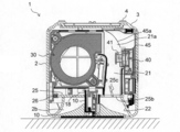
- FIG. 3 is a vertical sectional view in which the blower of FIG. 1 is cut in a direction perpendicular to FIG. 2.
- FIG. 4 is a vertical cross-sectional view in which the blower of FIG. 1 is cross-sectioned with the viewpoint perpendicular to FIG. 2 and opposite to FIG. 3.
- FIG. 6 is a vertical sectional view of the blower of FIG. 5 taken along a direction perpendicular to FIG.
- FIG. 7 is a vertical sectional view similar to FIG. 6, showing a state where the bottom plate of the housing is removed. It is a perspective view of an ion generating element. It is a vertical sectional view showing the state where the air blower according to the embodiment of the present invention falls and is inverted. It is a schematic diagram which shows schematic structure of a charged particle generation part.
- the blower 1 includes a cubic synthetic resin casing 2.
- the right hand side of the user facing the front of the housing 2 is defined as the right side surface of the housing 2, and the left hand side is defined as the left side surface of the housing 2.
- FIG. 9 is a right side view of the blower 1.
- the casing 2 has a cubic shape as described above, and includes six side surfaces (this “side surface” includes the top surface and the bottom surface).
- a suction port is formed on one of the six side surfaces, and a blow-out port is formed on one side surface other than the side surface where the suction port is formed.
- a suction port 2 a (see FIG. 3) is formed on the left side surface of the housing 2, and an air outlet 2 b is formed on the upper surface of the housing 2.
- the suction port 2a is composed of a set of a plurality of through holes.
- the blower outlet 2b has a circular front shape (here, a shape when viewed from above). Moreover, the blower outlet 2b becomes a shape which squeezes down in the shape of a mortar.
- the formation of the air outlet 2b is limited to only one side of the housing 2, but there is no such limitation with respect to the air inlet 2a. It is good also as forming the suction inlet 2a in the some side surface of the housing
- the casing 2 is molded as a single part on the side and top surfaces of the four circumferences, and only the bottom surface is constituted by a separate bottom plate 3.
- the bottom plate 3 is detachable, and rubber legs 4 for stably supporting the housing 2 on the table are provided at the four corners.
- a through hole 3a is formed in the bottom plate 3, and a terminal 35 is disposed in the back of the through hole 3a.
- the power cord 5 may be connected to a household 100V power source or may be connected to a USB terminal of a personal computer or the like.
- two operation buttons are arranged on the right side surface of the housing 2 so as to be lined up and down.
- the upper one is an air volume switching button 50 for switching the air volume of a blower fan to be described later. Each time the air volume switching button 50 is pressed, the air volume is switched from weak to medium to strong.
- An air volume indicator 51 is arranged on the air volume switching button 50.
- the air volume indicator 51 indicates the air volume by the number of vertically long LED lamps. A display with only one LED lamp indicates “low”, and a display with two LED lamps indicates “medium”. A display in which three LED lamps are arranged represents the air volume “strong”.
- the operation button below the air volume switching button 50 is a reset button 52.
- the reset button 52 is pressed after cleaning (cleaning) of a filter and an ion generating element, which will be described later, and indicates the accumulated time from the previous cleaning stored in the control unit (not shown) of the blower 1. It works to reset to zero.
- an indicator 53 for notifying that the filter maintenance time has come is arranged.
- the indicators 53 and 54 are both constituted by LED lamps.
- a hooking hole 2 c having a so-called Dharma hole shape is formed on the back surface of the housing 2. If the retaining hole 2c is hooked on a hook (not shown) protruding from the wall surface of the room, the blower device 1 can be held and used in a wall-hanging state.
- a blower fan 30 is disposed inside the housing 2.
- the blower fan 30 includes a casing 30a, a sirocco fan 30e disposed therein, and a motor 30f that rotates the sirocco fan 30e about a horizontal axis.
- the sirocco fan 30e is of a double-sided suction type, and the casing 30a is formed with an intake port 30b facing one suction surface of the sirocco fan 30e and an intake port 30c facing the other suction surface of the sirocco fan 30e. Yes.
- the intake port 30b is on the side facing the intake port 2a, and the intake port 30c is on the opposite side.
- the suction duct 20 and the duct member 32 are arranged so as to sandwich the blower fan 30 from the left and right.
- the suction duct 20 and the duct member 32 are connected to each other in such a manner that a hook 32e formed at the lower end of the duct member 32 is engaged with a hook receiver 20a formed at the lower end of the suction duct 20.
- the upper ends of the suction duct 20 and the duct member 32 are engaged with the hook and the hook receiver in the same manner as the lower end, and then the connecting member 36 is placed on the upper end of the suction duct 20 and the duct member 32 through the connecting member 36.
- the screw 37 is connected by screwing.
- the blower fan 30 is fixed to the duct member 32 with screws not shown.
- the suction duct 20 extends so as to connect the air inlet 30b of the blower fan 30 and the air inlet 2a of the housing 2.
- a filter 23 detachable from the bottom surface of the housing 2 is disposed between the inlet of the suction duct 20 and the suction port 2a.
- the duct member 32 has a vertical wall portion 32a facing the intake port 30c of the blower fan 30, and an opening portion 32b is formed there.
- a chamfered portion 32c formed at a corner at the lower back of the duct member 32 also serves as an air passage.
- a circuit board 34 on which electronic components such as terminals 35 are mounted is arranged inside the duct member 32 with its plane being vertical, and the circuit board 34 is located in the airflow toward the opening 32b. Electronic components that generate heat can be cooled. If the opening 32b is arranged at a position closer to the upper side of the duct member 32, the air flowing into the duct member 32 from the lower side moves a long distance along the circuit board 34, and the cooling effect is improved.
- the exhaust port 30d (refer FIG. 2) opened toward the front of the housing
- the air discharged from between the fan blades of the sirocco fan 30e swirls clockwise in FIG. 2 in the casing 30a, and is blown out substantially horizontally from the exhaust port 30d.
- the air flow blowing direction from the exhaust port 30d may be a diagonally upward direction with a slight elevation angle, or a diagonally downward direction with a slight depression angle.
- the air blown out from the exhaust port 30d is blown out from the blowout port 2b via a blower passage formed inside the housing 2.
- the blowout duct 21 constitutes the air passage.
- the blowout duct 21 receives the air blown from the exhaust port 30d from the inlet at the lower end, changes the direction of the air flow from the substantially horizontal direction to the vertical direction at the bent portion following the inlet, and blows the air upward from the outlet at the upper end.
- the straight line portion that follows the bent portion in the blowout duct 21 does not necessarily extend in the vertical direction. It may be extended obliquely with a slight angle (for example, an angle within 10 °).
- the bent part of the blowout duct 21 is a static pressure conversion region 21a in which the dynamic pressure of the airflow blown from the exhaust port 30d is converted into a static pressure.
- the ion generating element 40 is disposed immediately after the static pressure conversion region 21a.
- the ion generating element 40 is for discharging ions into the airflow blown out of the housing 2 from the blower outlet 2b.
- the ion generating element 40 is held by a holding member 45 that constitutes a part of the blowing duct 21.
- the holding member 45 is formed with a bent portion 45a on the outer peripheral side of the bent portion of the blowout duct 21.
- the bent portion 45a is a curved surface that gently transitions from the blowing direction of the blower fan 30 to the direction of the blowout port 2b.
- blowing airflow hits from the front, and dynamic pressure is converted into a static pressure.
- the blown airflow is smoothly redirected by the curved surface and guided upward. As a result, both airflows merge and are supplied to the ion generating element 40 while maintaining the airflow velocity while spreading in the lateral width direction of the blowout duct 21.
- the bent portion 45a is a curved surface that gently changes from the blowing direction of the blower fan 30 to the outlet 2b, but the bent portion 45a is formed to be bent substantially at a right angle like an elbow pipe. May be.
- the ion generating element 40 has a thin flat box-like casing in the front-rear direction, and faces the blower fan 30 on the front surface of the casing (the rear face in the direction of the entire blower 1).
- a pair of left and right needle-like discharge electrodes 41 serving as an ion generating portion project from the side surface) toward the blower fan 30.
- the discharge electrode 41 generates ions by corona discharge.
- the discharge electrode 41 is directly above the bent portion 45a, more precisely, immediately after the connecting portion between the bent portion 45a and the straight portion of the outlet duct 21 that connects the bent portion 45a to the outlet 2b, that is, immediately after the static pressure conversion region 21a.
- it may be located in the middle of the bent portion 45a, that is, in the static pressure conversion region 21a.
- One of the pair of discharge electrodes 41 is a positive ion generation part and the other is a negative ion generation part, and is arranged at a predetermined distance in the horizontal direction.
- the interval between the pair of discharge electrodes 41 is wider than the width of the exhaust port 30 d of the blower fan 30. In other words, each of the pair of discharge electrodes 41 is disposed outside the air flow blowing width of the blower fan 30.
- the holding member 45 is connected to the exhaust port 30d of the blower fan 30 from the opening 45b having substantially the same width as the exhaust port 30d (the entire blower 1).
- the front portion is a symmetrically extending portion 45c.
- the discharge electrode 41 is positioned in the lateral width of the overhanging portion 45c.
- the blowout duct 21 extends to the outlet at the upper end with the same lateral width as the overhanging portion 45c on the downstream side of the overhanging portion 45c.
- an airflow branching portion 45d that distributes the airflow from the blower fan 30 to both discharge electrodes 41 is formed.
- the airflow branching portion 45 d is composed of a vertical wall protruding in the direction of the blower fan 30.
- the ion generating element 40 is held by inserting the casing into the holding member 45 from above.
- a connection terminal 40 a connected to the terminal portion 42 inside the housing 2 is formed on the upper surface of the housing of the ion generating element 40.
- An electrode protection plate 40b for preventing the discharge electrode 41 from coming into contact with another object is attached to the front surface of the housing. For this reason, there is no need to worry that the discharge electrode 41 hits another object and deforms.
- a circular through hole 40 c is formed in the electrode protection plate 40 b at a location corresponding to the front surface of the discharge electrode 41. At least a part of the air passing through the static pressure conversion region 21a flows between the housing of the ion generating element 40 and the electrode protection plate 40b. Another part of the air passing through the static pressure conversion region 21a passes through the through hole 40 and is blown to the discharge electrode 41.
- the shape of the through hole 40 is circular in this embodiment, but may be other shapes.
- a light guide plate 25 is disposed above the blowout duct 21 so as to partition the inside of the housing 2 horizontally.
- the upper surface of the light guide plate 25 is applied to the lower edge of the air outlet 2b.
- a communication port 25b is formed in the light guide plate 25 on the side close to the front surface of the housing 2, and an outlet at the upper end of the outlet duct 21 is connected to the communication port 25b.
- a guide plate 25 c that guides the airflow rising inside the blowout duct 21 toward the front is formed in the communication port 25 b so as to protrude into the blowout duct 21.
- the light guide plate 25 is made of a transparent material such as acrylic resin, and the rear end serves as the incident surface 25a.
- a light emitting diode (LED) 26 serving as a light source is arranged in a shape facing the incident surface 25a.
- a reflection sheet (not shown) is overlaid on the lower surface of the light guide plate 25.
- a through hole 25d is formed at the center of the light guide plate 25. This location is the center of the air outlet 2b and also the center of the housing 2.
- the shaft portion 17 rising from the connecting member 36 passes through the through hole 25 d and protrudes from the upper surface of the light guide plate 25.
- the wind direction plate 10 is supported on the shaft portion 17.
- the wind direction plate 10 is an umbrella-shaped synthetic resin part having a circular planar shape and is slightly smaller in diameter than the air outlet 2b.
- the wind direction plate 10 pops up on the upper surface of the housing 2 as will be described later, but since it is circular, it does not feel pain even if it is touched by the user's fingers.
- the lower surface of the wind direction plate 10 is a conical inclined surface 10a.
- a circular name plate 10 b is fitted on the upper surface of the wind direction plate 10.
- the wind direction plate 10 is attached to a slide body that can slide with respect to the housing 2.
- What constitutes the slide body in the present embodiment is a sleeve 11 protruding downward from the center of the lower surface of the wind direction plate 10.
- the sleeve 11 is fitted to the outside of the shaft portion 17 and slides up and down along the shaft portion 17.
- a configuration in which a sleeve-like member is disposed on the side of the housing 2 and the shaft-like member inserted therein is a slide body is also possible.
- a compression coil spring 16 is disposed between the sleeve 11 and the shaft portion 17, and the compression coil spring 16 serves as a biasing unit that biases the sleeve 11 toward the outside of the housing 2.
- the sleeve 11 is provided with a push-on / push-off locking means that holds the sleeve 11 against the urging force of the compression coil spring 16.
- Push-on / push-off type locking means that pops up when pressed and pops up and returns to the retracted position when pressed again is well known for knock-type ballpoint pens and electrical appliance switches, and the mechanism Various things are known.
- the first locking portion 17a and the second locking portion 17b that are formed on the side surface of the shaft portion 17 so as to be lined up and down, and the first locking portion 17a and the first locking portion provided inside the sleeve 11 are provided.
- the engaging member 12 that selectively engages with one of the two locking portions 17b constitutes a push-on / push-off type locking means 19.
- the wind direction plate 10 is popped up from the housing 2, and the engagement member 12 engages with the first locking portion 17 a to keep the wind direction plate 10 from protruding further. .
- a gap between the wind direction plate 10 and the air outlet 2b is greatly opened, and this is referred to as “the air outlet is opened” in this specification.
- the wind direction plate 10 is pushed into the housing 2 against the urging force of the compression coil spring 16 and is located in the air outlet 2b.
- the engaging member 12 engages with the second locking portion 17b to keep the wind direction plate 10 at its height.
- the gap between the wind direction plate 10 and the air outlet 2b is reduced, and this is referred to as “the air outlet is closed” in this specification.
- occludes the blower outlet 2b completely may be sufficient.
- the wind direction plate 10 does not contact the air outlet 2b, although the gap with the air outlet 2b is reduced. This is because in order to pop up the wind direction plate 10 again, it is necessary to depress the wind direction plate 10 again, and a space corresponding to the depressing stroke is required under the wind direction plate 10. However, if the inner surface of the air outlet 2b does not sag downward and the air direction plate 10 can be pushed down even after the air direction plate 10 comes into contact therewith, the air direction plate 10 is brought into contact with the air outlet 2b. In this case, the air outlet 2b may be completely closed.
- the displacement of the wind direction plate 10 as described above is used for on / off control of the power switch of the blower fan 30.
- the power switch 18 is installed under the light guide plate 25 and makes the actuator interfere with the slide locus of the sleeve 11.
- the power switch 18 of the blower fan 30 can be switched on or off in accordance with the movement of the wind direction plate 10 opening or closing the air outlet 2b, the operation button or the operation lever of the power switch 18 is switched. Need not be provided on the outer surface of the housing 2, and the design of the blower 1 can be made clean. Further, if the position of the wind direction plate 10 is seen, the switching state of the power switch 18 can be known at a glance even from a distance.
- the air outlet 2b opens, and at the same time, the power switch 18 is turned on.
- the air outlet 2b is closed and the power switch 18 is turned on. It is also possible to configure so that is turned off.
- the blower fan 30 starts rotating as soon as the power switch 18 is turned on.
- the blower fan 30 may be configured not to be driven only when the power switch 18 is turned on, but to start rotating with the further operation such as the air volume setting by the air volume switching button 50 as an opportunity.
- the operation of the blower 1 will be described. If the wind direction plate 10 is pushed into the pop-up state with the power cord 5 connected to the power source, the power switch 18 is turned on and the blower fan 30 starts rotating.
- the ion generating element 40, the LED 26, and the air volume indicator 51 are also energized, the ion generating element 40 starts generating ions, the LED 26 starts illuminating the light guide plate 25, and the air volume indicator 51 is set at that time. Start displaying the air volume.
- the air sucked into the casing 30a is sucked into the sirocco fan 30e, discharged from between the fan blades of the sirocco fan 30e, and blown out from the exhaust port 30d.
- the air blown out in the horizontal direction from the exhaust port 30d enters the blowout duct 21 and is redirected to a vertical airflow toward the blowout port 2b in the static pressure conversion region 21a.
- the dynamic pressure of the airflow is converted into a static pressure. Once the dynamic pressure is converted to static pressure, the airflow rises inside the blowout duct 21, and ions generated from the ion generating element 40 are mixed in the air in the middle.
- a high voltage having an AC waveform or an impulse waveform is applied to the discharge electrode 41 of the ion generating element 40, whereby the discharge electrode 41 performs corona discharge.
- a positive voltage is applied to one of the discharge electrodes 41, and water molecules in the air are ionized by corona discharge to generate hydrogen ions. This hydrogen ion is clustered with water molecules in the air by solvation energy. As a result, positive ions of air ions composed of H + (H 2 O) m (m is 0 or an arbitrary natural number) are released.
- a negative voltage is applied to the other discharge electrode 41, and oxygen ions or water molecules in the air are ionized by corona discharge to generate oxygen ions.
- This oxygen ion is clustered with water molecules in the air by solvation energy.
- negative ions of air ions composed of O 2 ⁇ (H 2 O) n (n is an arbitrary natural number) are released.
- H + (H 2 O) m and O 2 ⁇ (H 2 O) n aggregate around the surface of airborne bacteria and odorous components and surround them. Then, as shown in the following formulas (1) to (3), [• OH] (hydroxyl radical) and H 2 O 2 (hydrogen peroxide), which are active species, are aggregated on the surface of a microorganism or the like by collision. To destroy airborne bacteria and odorous components.
- m ′ and n ′ are arbitrary natural numbers. Accordingly, by sending positive ions and negative ions into the room from the air outlet 2b, the room can be sterilized and the odor can be removed.
- the pair of discharge electrodes 41 are arranged apart in the left-right direction, which is a direction perpendicular to the airflow. For this reason, the positive ions generated at one discharge electrode 41 and the negative ions generated at the other discharge electrode 41 are less likely to recombine and disappear due to each other's collision, thereby increasing the amount of ions delivered. Can do. If both the discharge electrode 41 serving as the positive ion generation unit and the discharge electrode 41 serving as the negative ion generation unit are arranged outside the air flow blowing width of the blower fan 30 as in the present embodiment, The disappearance due to recombination of ions and negative ions can be further reduced.
- Passing through the discharge electrode 41 while entraining ions generated by the discharge electrode 41 is air whose dynamic pressure has been converted to static pressure in the static pressure conversion region 21a.
- the velocity component of the airflow once disappears, and an airflow directed toward the discharge electrode 41, which is an ion generation unit, is generated by the static pressure.
- the amount of airflow passing through 41 is not significantly affected. Therefore, even if the discharge electrode 41 is disposed outside the air blowing width of the blower fan 30, a sufficient air flow passing through the discharge electrode 41 can be secured and ions can be efficiently delivered.
- the airflow blown from the blower fan 30 is evenly distributed to the left discharge electrode 41 and the right discharge electrode 41 by an airflow branching portion 45d formed in the bent portion 45a. Therefore, there is no air volume imbalance between the air flow for sending positive ions and the air flow for sending negative ions.
- At least a part of the air passing through the static pressure conversion region 21a flows between the casing of the ion generating element 40 and the electrode protection plate 40b. Therefore, the presence of airflow passing through the discharge electrode 41 is ensured, and ions generated at the discharge electrode 41 can be reliably delivered.
- the horizontal air flow blown from the blower fan 30 is converted into a vertical air flow toward the outlet 2b, and the static pressure conversion region 21a for converting the dynamic pressure of the air flow into static pressure or ions immediately thereafter Since the ion generating part of the generating element 40 is arranged, it is not necessary to make the blowing duct 21 that is a blowing path long in the vertical direction for the arrangement of the ion generating element 40, and the height of the blowing device 1 is suppressed. be able to.
- the connection portion between the bent portion 45a and the straight portion of the outlet duct 21 that connects the bent portion 45a to the outlet 2b is “the dynamic pressure of the blown airflow is converted into the static pressure.
- the ion generating portion of the ion generating element 40 at this location, the disappearance due to recombination of positive ions and negative ions can be further reduced, and the height of the charged particle delivery device 1 can be suppressed. it can.
- the air containing positive ions and negative ions ascends inside the blowout duct 21 as indicated by an arrow B1 in FIG. 2, passes through the communication port 25b of the light guide plate 25, and exits into the blowout port 2b.
- the air that has flowed into the air outlet 2b continues to rise as indicated by arrow B2 and strikes the lower surface of the wind direction plate 10. And it blows out outside at an angle closer to the horizontal as shown by an arrow B3.
- the air can flow out from the entire area of the annular outflow portion 8 formed between the air outlet 2b and the wind direction plate 10, but actually, the communication port 25b opens at a position in front of the shaft portion 17 and communicates. Since the guide plate 25c provided at the opening 25b also guides the airflow toward the front, the air blowing is concentrated in the forward direction.
- a recess 22 is formed on the inner surface of the air outlet 2b.
- the inner surface of the air outlet 2b squeezes while drawing a curve that is convex toward the central direction at locations other than the recesses 22, whereas the recess 22 linearly squeezes.
- the recess 22 formed in this manner the gap width with the wind direction plate 10 is widened, and more air flows out from here.
- the air flow including ions concentrates around the user, and the user is given both a physical cooling sensation by the wind and a cooling sensation by the ions. Become.
- the ions also sterilize and deodorize around the user. Furthermore, air circulation occurs in the room by the air flow blown out from the blower 1, and sterilization and deodorization are promoted throughout the room.
- the LED 26 When the power switch 18 is turned on, the LED 26 is turned on, and the LED 26 emits light in the horizontal direction.
- the light emitted from the LED 26 enters the light guide plate 25 from the incident surface 25a. Since the light guide plate 25 is processed to reflect light upward, the light changes its direction inside the light guide plate 25 and strikes the lower surface 10 a of the wind direction plate 10. The light is reflected radially on the lower surface of the wind direction plate 10 and indirectly illuminates the surroundings of the blower device 1. Since light is not reflected upward at the location of the communication port 25b, there is little light that hits the front portion of the lower surface 10a of the wind direction plate 10, and the user in front of the blower 1 does not have to feel glare.
- a separate switch may be provided for the LED 26 so that the user can select whether to turn on the LED 26 in conjunction with the pop-up of the wind direction plate 10.
- the wind direction plate 10 is pushed down to return from the pop-up state of FIG. 1 to the storage state of FIG. Then, the power switch 18 is turned off, and the blower fan 30 and the ion generating element 40 stop operating. The LED 26 and the air volume indicator 51 are turned off.
- the control unit (not shown) of the blower 1 turns on the indicator 53.
- the control unit turns on the indicator 54.
- the screws 38 shown in FIG. 12 fix the bottom plate 3 to the housing 2.
- the screw 38 is of a type that can be turned with a coin, and the bottom plate 3 can be removed without a screwdriver.
- the screw 38 is prevented from being detached from the bottom plate 3, and there is no fear of losing it.
- the filter 23 can be pulled out from the lower surface opening of the housing 2.
- the extracted filter 23 is returned to its original position after being cleaned.
- the ion generating element 40 can be maintained by pulling the holding member 45 together with the ion generating element 40 and then removing the ion generating element 40 from the holding member 45.
- the ion generating element 40 is attached to the holding member 45 again, and the holding member 45 is returned to the original position.
- the holding member 45 is placed in a predetermined position that becomes a part of the blowing duct 21, the connection terminal 40 a comes into contact with the terminal portion 42, and electrical connection to the ion generating element 40 is established.
- the bottom plate 3 is fixed to the housing 2 and the plug 6 of the power cord 5 is connected to the terminal 35, the blower 1 is ready for use again.
- the blower device 1 Since the blower device 1 has a small cubic shape, there is a possibility that it will fall over when it hits it. As shown in FIG. 15, the upside down may be inverted. It is meaningless for the blower 1 to continue operation in such a state. Therefore, it is preferable that the operation of the blower 1 is automatically stopped when it is in an inverted state.
- the blower 1 having the structure according to the present invention can meet the above request relatively easily. If the wind direction plate 10 is in the pop-up state when the inverted state shown in FIG. 15, that is, the state in which the wind direction plate 10 is installed with the surface on which the air outlet 2 b is formed facing down, the blower 1 is grounded by the wind direction plate 10. Since the entire mass of the blower device 1 excluding the mass of the wind direction plate 10 and the member that moves together is applied to the compression coil spring 16, it is sufficient that the urging force of the compression coil spring 16 is lost to this mass. If it does so, the wind direction board 10 which was a pop-up state will be retracted in the blower outlet 2b by the inversion of the air blower 1, and the power switch 18 will be turned off. As a result, the operation of the blower 1 is stopped.
- the ion generating element 40 is incorporated in the air blower 1 and the air flow containing ions combined with moisture in the air is sent out, not just air blowing, but charged particles other than ions are included in the air flow. It is good as well. Examples of charged particles other than ions include charged fine particle water. If an electrostatic atomizer is used, the charged fine particle water containing a radical component can be produced
- FIG. 7, FIG. 1, FIG. 9, and FIG. 10 show a top view, a bottom view, a left side view, and a rear view of the blower according to the first embodiment.
- the blower device 1 includes a cubic housing 2, and a suction port 2 a (see FIG. 3) is opened on the left side surface of the housing 2, and an air outlet 2 b is opened on the upper surface.
- the blower outlet 2b is formed in a circular shape, and a wind direction plate 10 supported so as to be movable up and down with respect to the housing 2 is disposed to face the blower outlet 2b.
- the bottom plate 3 of the housing 2 is detachably provided, and rubber legs 4 are provided at the four corners of the bottom plate 3. Thereby, the air blower 1 can be installed and used on a desktop etc. Further, the rear surface of the housing 2 is provided with a hooking hole 2c that is hooked on a hook provided on a wall surface in the room. Thereby, the air blower 1 can also be hung on a wall surface and used.
- a power cord 5 is connected to the right end of the bottom surface of the housing 2. As will be described in detail later, the power cord 5 is connected by inserting a plug 6 provided at one end into a terminal portion 35 (see FIG. 3) through an insertion hole 3a (see FIG. 3) provided in the bottom plate 3. The other end of the power cord 5 is connected to a power supply source such as a commercial power source or a USB terminal to supply power to the blower 1.
- a power supply source such as a commercial power source or a USB terminal to supply power to the blower 1.
- the wind direction plate 10 has a circular planar shape having substantially the same diameter as the air outlet 2b, and the lower surface 10a is formed in a substantially truncated cone shape having an inclined surface.
- a sleeve 11 is attached to the center of the wind direction plate 10.
- the sleeve 11 is fitted to a shaft portion 17 disposed on the housing 2, and can move up and down relative to the housing 2 together with the wind direction plate 10.
- the shaft portion 17 passes through a through hole 25d opened at the center of a light guide plate 25 described later, and is supported by a duct member 32 disposed in the housing 2.
- the shaft portion 17 is provided with first and second locking claws 17a and 17b arranged in the vertical direction and a compression spring 16 for urging the wind direction plate 10 upward.
- An engagement member 12 that engages with the first and second locking claws 17 a and 17 b is attached in the sleeve 11.
- a power switch 18 is disposed on the upper surface of the duct member 32.
- the wind direction plate 10 urged by the compression spring 16 moves between a position where the air outlet 2b is opened and a position where the air outlet 2b is opened by the engagement of the first and second locking claws 17a, 17b and the engaging member 12. That is, as shown in the figure, when the engaging member 12 is engaged with the second locking claw 17b, the air outlet 2b is opened. At this time, the power switch 18 is turned on.
- the airflow direction plate 10 When the airflow direction plate 10 is pressed from the open state of the air outlet 2b and the engaging member 12 engages with the first locking claws 17a as shown in FIG. 6, the airflow direction plate 10 closes the air outlet 2b. At this time, the sleeve 11 contacts the power switch 18, and the power switch 18 is turned off. Moreover, if the wind direction board 10 is pushed down from the state which closed the blower outlet 2b, as shown in FIG. 2, the wind direction board 10 will pop up.
- the power switch 18 is turned on and off by the vertical movement of the wind direction plate 10, and the blower fan 30, the ion generating element 40 and the LED 26, which will be described later, are driven when the power switch 18 is turned on. Further, when the air outlet 2b is opened, an annular outflow portion 8 is formed by which the airflow is radially sent out between the air outlet 2b and the wind direction plate 10 by the air direction plate 10 having substantially the same diameter as the air outlet 2b.
- the duct member 32 is disposed in the lower part of the housing 2 and is formed in a box shape with an opening surface at one end facing the suction port 2a.
- a blower fan 30 made of a sirocco fan covered with a casing 30a is disposed in the duct member 32.
- the blower fan 30 is screwed and held on a fan holding portion 32a formed of the right side wall of the duct member 32.
- the casing 30a has intake ports 30b and 30c on both sides in the axial direction and an exhaust port 30d on the end surface in the circumferential direction.
- the duct member 32 forms the suction duct 20 that connects the suction port 2a and the one suction port 30b.
- a filter 23 detachable from the bottom surface of the housing 2 is disposed at the suction port 2a.
- the opening 32b facing the air inlet 30c is opened on the right side wall of the duct member 32, and a notch 32d (see FIG. 4) is provided on the right end on the back side. Further, a chamfer 32c (see FIG. 4) is applied to the bottom of the duct member 32 on the back side.
- a circuit board 34 on which electronic parts such as the terminal portion 35 are mounted is erected and disposed.
- the airflow flowing into the suction duct 20 from the suction port 2a by driving the blower fan is guided to the suction port 32b as indicated by an arrow A1. Further, as shown by an arrow A2 in the rear sectional view of FIG. 4, a part of the airflow flows out from the duct member 32 through the notch 32d and flows downward, and flows outside the chamfer 32c to the left. . The airflow flows upward between the circuit board 34 and the duct holding portion 32a, and is guided to the intake port 32c through the opening 32b.
- the air current can be sucked in from both sides in the axial direction of the blower fan 30 through a plurality of paths, and the blower efficiency can be improved.
- the electronic component mounted on the circuit board 34 can be cooled by the airflow.
- the opening 32 b is provided above the center of the blower fan 30 and faces the upper portion of the standing circuit board 34. Thereby, the cooling effect of the circuit board 34 by the airflow which distribute
- the first blowout duct 21 is provided in front of the exhaust port 30d of the blower fan 30. Above the first outlet duct 21, a second outlet duct 22 that opens the outlet 2b is provided.
- the 1st blowing duct 21 and the 2nd blowing duct 22 are connected via the communicating port 25b of the light-guide plate 25 mentioned later.
- FIG. 14 shows a perspective view of the holding member 45 holding the ion generating element 40.
- the holding member 45 has a bent portion 45a in which an opening 45b having substantially the same width in the left-right direction as the exhaust port 30d is opened at the rear end face and the flow path is widened in the left-right direction.
- the front wall 45c of the bent portion 45a is formed by a curved surface continuous with the lower end of the casing 30a of the blower fan 30, and is inclined to face the exhaust port 30d.
- the airflow is bent and guided upward through the bent portion 45a.
- the air flow sent out from the exhaust port 30b collides with the front wall 45c of the bent portion 45a, and the dynamic pressure is converted into a static pressure and decelerated.
- the dynamic pressure is also converted to static pressure by the widening of the flow path by the bent portion 45a, and the airflow is further decelerated. Therefore, the bending part 45a comprises the static pressure conversion part which converts the dynamic pressure of an airflow into a static pressure.
- a partition plate 45d extending vertically is provided on the front wall 45c of the bent portion 45a at the central portion facing the opening 45b.
- the ion generating element 40 has a pair of needle-shaped discharge electrodes 41 arranged in parallel in the left-right direction facing the first blowing duct 21.
- the discharge electrode 41 is disposed immediately above the bent portion 45a, and the distance between both the discharge electrodes 41 is formed wider than the width of the opening 45b.
- the discharge electrode 41 of the ion generating element 40 generates a corona discharge by applying a high voltage having an AC waveform or an impulse waveform.
- a positive voltage is applied to one of the discharge electrodes 41, and water molecules in the air are ionized by corona discharge to generate hydrogen ions.
- This hydrogen ion is clustered with water molecules in the air by solvation energy.
- positive ions of air ions composed of H + (H 2 O) m (m is 0 or an arbitrary natural number) are released.
- a negative voltage is applied to the other discharge electrode 41, and oxygen ions or water molecules in the air are ionized by corona discharge to generate oxygen ions.
- This oxygen ion is clustered with water molecules in the air by solvation energy.
- negative ions of air ions composed of O 2 ⁇ (H 2 O) n (n is an arbitrary natural number) are released.
- H + (H 2 O) m and O 2 ⁇ (H 2 O) n aggregate around the surface of airborne bacteria and odorous components and surround them. Then, as shown in the formulas (1) to (3), active species [ ⁇ OH] (hydroxyl radicals) and H 2 O 2 (hydrogen peroxide) are agglomerated and produced on the surface of microorganisms or the like by collision. Destroy airborne bacteria and odorous components.
- m ′ and n ′ are arbitrary natural numbers. Accordingly, by sending positive ions and negative ions into the room from the air outlet 2b, the room can be sterilized and the odor can be removed.
- the discharge electrode 41 is disposed immediately above the bent portion 42a, ions generated at the discharge electrode 41 are included in the airflow that has been decelerated by being converted into static pressure by the bent portion 42a. Thereby, the ion which generate
- the distance between the discharge electrodes 41 is larger than the width of the opening 45b and the discharge electrodes 41 are arranged on both sides of the opening 45b, ions can be more reliably included in the decelerated airflow. .
- the flow rate of the airflow flowing around each discharge electrode 41 can be made substantially equal by the partition plate 45d, and positive ions and negative ions can be contained uniformly.
- the holding member 45 can be detached from the bottom surface of the housing 2 by removing the bottom plate 3 as shown in FIG. Thereby, the ion generating element 40 can be replaced
- the blade 30e (see FIG. 3) of the blower fan 30 can be cleaned through the exhaust port 30d exposed by the attachment and detachment of the holding member 45.
- the filter 23 (see FIG. 3) can be detached from the bottom surface of the housing 2 by removing the bottom plate 3, and the filter 23 can be easily cleaned.
- the ion generating element 40 has the connection terminal 40a on the upper surface.
- the connection terminal 40 a comes into contact with the terminal portion 42 provided in the housing 2 so that power can be supplied to the ion generating element 40. For this reason, the weight of the ion generating element 40 is not weighted to the terminal part 42, and the failure of the terminal part 42 by continuing weighting can be prevented.
- the bottom plate 3 of the housing 2 can be removed with the plug 6 (see FIG. 3) of the power cord 5 removed as shown in the bottom view of FIG. Thereby, the electric shock by being energized when the bottom plate 3 is removed can be prevented.
- a light guide plate 25 is horizontally disposed on the upper surface of the first outlet duct 21.
- the light guide plate 25 is formed in a flat plate shape by a transparent member such as acrylic, and an LED 26 (light source) is disposed so as to face the incident surface 25a on the rear end surface.
- a reflection sheet (not shown) is disposed on the lower surface of the light guide plate 25.
- the light emitted from the LED 26 enters the light guide plate 25 from the incident surface 25a and is guided, and the light incident on the upper and lower surfaces at an incident angle smaller than the critical angle is emitted. At this time, the light emitted from the lower surface of the light guide plate 25 is reflected upward by the reflection sheet. Thereby, light is emitted from the upper surface (emission surface) of the light guide plate 25 toward the air outlet 2b.
- a through hole 25d through which the shaft portion 17 passes is opened at the center of the light guide plate 25, and a communication port 25b is opened at the front portion opposite to the incident surface 25a with respect to the through hole 25d. Since the 1st blowing duct 21 is distribute
- a second blowing duct 22 is provided above the light guide plate 25.
- the 2nd blowing duct 22 has the blower outlet 2b on the upper surface, and is formed in the cylinder shape concentric with the blower outlet 2b.
- the vertical cross section of the inner wall 22a of the second blow-out duct 22 is formed in a curved shape with a narrow bottom.
- FIG. 8 shows a top view of the housing 2 with the wind direction plate 10 omitted.
- the communication port 25b of the light guide plate 25 is provided with a wind direction variable portion 25c that guides the airflow rising through the first blowout duct 21 forward and is provided in a lattice shape.
- the front part of the second blow-out duct 22 is provided with a recess 22b that is recessed in the inner wall 22a.
- the inner surface of the recess 22b is formed of a conical surface having a straight vertical section, and the lower end of the recess 22b is formed along the communication port 25b and the upper end is formed inside the periphery of the outlet 2b.
- the air blowing fan 30, the ion generating element 40, and the LED 26 are driven.
- Airflow dust flowing into the housing 2 from the suction port 2a is collected by the filter 23, flows through the suction duct 23 as shown by an arrow A1, and is guided to the blower fan 30 from the suction port 30b. Further, a part of the airflow flows outside the duct member 32 as indicated by an arrow A2, and is guided to the blower fan 30 from the intake port 30c.
- the airflow sent from the exhaust port 30d of the blower fan 30 ascends the first blowing duct 21 as shown by an arrow B1 (see FIG. 2).
- ions generated by the ion generating element 40 are included in the airflow.
- the air flow containing ions flows into the second blowout duct 22 through the communication port 25b and rises as shown by an arrow B2 (see FIG. 2), and then radiates from the outflow portion 8 as shown by an arrow B3 (see FIG. 2). Is sent out.
- the airflow flows into the second outlet duct 22 from the communication port 25b disposed in the front portion of the housing 2, and the airflow is guided forward by the wind direction variable portion 25c. Moreover, the flow path width of the front part between the 2nd blowing duct 22 and the wind direction board 10 is expanded by the recessed part 22b. As a result, more airflow than the surroundings is sent to the front of the blower 1.
- the light guided through the light guide plate 25 by driving the LED 26 is emitted toward the air outlet 2b and is reflected radially by the lower surface 10a of the wind direction plate 10.
- the indirect illumination around the air blower 1 can be performed.
- the light emitted from the front portion of the light guide plate 25 is reduced by the communication port 25b.
- the communication port 25b is disposed on the opposite side of the incident surface 25a with respect to the shaft portion 17, light emitted from the front portion of the light guide plate 25 can be further reduced.
- the rubber legs 4 are provided at the four corners of the bottom plate 3.
- the four rubber legs 4 constitute an installation portion that stably supports the blower device 1 by abutting against an installation surface 50 such as a tabletop when the blower device 1 is used.
- the plug 6 is electrically connected by being inserted into the terminal portion 35.
- the plug 6 has a predetermined length and may not be electrically connected due to poor contact or the like depending on the degree of insertion into the terminal portion 35. Therefore, in this embodiment, when the rubber legs 4 and the plugs 6 provided at least at the four corners of the bottom plate 3 are in contact with the installation surface 50, the plug 6 and the terminal portion 35 are electrically connected (conducted). .
- the plug 6 is not firmly inserted into the terminal portion 35
- the blower 1 is installed on the installation surface 50 in a state where the plug 6 is not firmly inserted into the terminal portion 35 (that is, the state where the plug 6 and the terminal portion 35 are not conductive)
- all the rubber legs 4 and the installation surface 50 are connected. Does not touch. In other words, one or more rubber legs 4 are in a floating state.
- the plug 6 is inserted into the terminal portion 35 by applying a force to the housing 2 so that all the rubber legs 4 and the installation surface 50 are in contact with each other. As a result, the plug 6 and the terminal portion 35 are electrically connected.
- the plug 6 and the terminal portion 35 are electrically connected. That is, since the plug 6 and the terminal portion 35 are electrically connected when the blower device 1 is stably installed on the installation surface 50, the conductive state between the plug 6 and the terminal portion 35 can be easily grasped. Moreover, even if the plug 6 is not sufficiently inserted into the terminal portion 35, the plug 6 and the terminal portion 35 can be easily conducted without directly touching the plug 6.
- the plug 6 is connected to the terminal portion 35 through an insertion hole 3 a that opens in the bottom plate 3 that can be attached to and detached from the housing 2. Further, since the bottom plate 3 is detachably formed by detaching the plug 6, it is necessary to remove the plug 6 from the terminal portion 35 in order to remove the bottom plate 3 from the housing 2. That is, when the bottom plate 3 is removed, power is not supplied to the blower 1, so when the user removes the bottom plate 3 and performs cleaning and maintenance inside the housing 2, the user touches various electronic components to receive an electric shock. There is nothing.
- the ion generating element 40 and the holding member 45 can be detached from the bottom surface of the housing 2 when the bottom plate 3 is removed, the ion generating element 40 and the holding member 45 can be easily replaced or cleaned. .
- the filter 23 can be detached from the bottom surface of the housing 2 when the bottom plate 3 is removed, the filter 23 can be easily replaced or cleaned.
- the holding member 45 has a function of holding the ion generating element 40 and also has a function as a part of the first blowing duct 21.
- the holding member 45 constitutes a duct near the ion generating element 40.
- the holding member 45 is arranged so as to be detachable integrally with the ion generating element 40 with respect to the housing 2. That is, since the duct in the vicinity of the ion generating element 40 is detachable, the inside of the duct in the vicinity of the ion generating element 40 can be easily cleaned. In addition, replacement and cleaning of the ion generating element 40 can be easily performed.
- the holding member 45 and the ion generating element 40 can be detached from the bottom surface side of the housing 2.
- an exhaust port 30d is provided in the vicinity of the bottom plate 3.
- the exhaust port 30 d can be visually recognized by removing the bottom plate 3 from the housing 2 and removing the holding member 45 and the ion generating element 40 from the housing 2. As described above, since the exhaust port 30d is provided in the vicinity of the bottom plate 3, access from the bottom surface side of the housing 2 is easy, and the exhaust port 30d can be easily cleaned.
- the direction of the air flow blown out from the exhaust port 30d is converted upward by the bent portion 45a, flows through the ducts 21 and 22, and is blown out from the air outlet 2b. Therefore, the exhaust port 30d can be easily cleaned, and the blower can blow out ions from the upper surface side of the housing 2. Further, by making the direction of the air flow blown out from the exhaust port 30d substantially perpendicular to the direction of the air flow flowing through the ducts 21 and 22, the direction of both air flows is made the same direction. The height of the device can be reduced. Therefore, the blower can be reduced in size.
- connection terminal 40 a is provided on the upper surface of the ion generating element 40 held by the holding member 45 that can be detached from the bottom surface side of the housing 2. Therefore, the weight of the ion generating element 40 and the holding member 45 is not applied to the connection terminal 40a. Thereby, failures such as damage and deformation of the connection terminal 40a can be prevented.
- the rubber legs 4 are provided at the four corners of the bottom plate 3, but the rubber legs 4 may not be provided.
- the plug 6 and the terminal portion 35 may be electrically connected when the installation portion provided on the bottom plate 3 and the plug 6 abut on the installation surface 50.
- the installation part provided in the baseplate 3 may be the whole of the surface facing the installation surface 50 or a part thereof. That is, what is necessary is just to contact
- the insertion hole 3a is provided in the bottom plate 3 and the plug 6 is inserted through the insertion hole 3a, the connection is made to the terminal portion 35.
- the present invention is not limited to this. That is, the blower 1 can be used by being hung on the wall surface as described above. Therefore, rubber legs (installation portions) and insertion holes may be formed on the back surface of the housing 2, and the plug 6 may be inserted into a terminal portion (not shown) provided on the back surface through the insertion holes formed on the back surface. . Then, when the rubber leg (installation portion) and the plug 6 are brought into contact with the wall surface, the plug 6 and the terminal portion provided on the back surface may be electrically connected. In this case, the back plate can be attached to and detached from the housing 2. That is, the plate part provided with the insertion hole into which the plug 6 is inserted may be detachable from the housing 2.
- the latching hole 2c latched on the hook provided on the wall surface of the room is provided on the back surface.
- the present invention is not limited to this, and any housing that does not impair the function of the blower 1 is provided. It may be provided at any position on the body 2.
- the bottom plate 3 may be provided with a retaining hole.
- charged fine particle water may be sent out as charged particles.
- charged fine particle water containing a radical component can be generated by an electrostatic atomizer. That is, condensed water is generated on the surface of the discharge electrode by cooling the discharge electrode provided in the electrostatic atomizer with a Peltier element. When a negative high voltage is applied to the discharge electrode, charged fine particle water is generated from the dew condensation water.
- the charged particle delivery device 1 includes a cubic synthetic resin casing 2.
- the right hand side of the user facing the front of the housing 2 is defined as the right side surface of the housing 2, and the left hand side is defined as the left side surface of the housing 2.
- FIG. 9 is a right side view of the charged particle delivery device 1.
- the housing 2 has a cubic shape as described above, and a suction port is formed on one of the four sides.
- a suction port 2 a (see FIG. 3) is formed on the left side surface of the housing 2.
- the suction port 2a is composed of a set of a plurality of through holes.
- the suction port 2 a may be formed on a plurality of side surfaces of the housing 2.
- a blower outlet 2 b is formed on the upper surface of the housing 2.
- the blower outlet 2b has a circular front shape (here, a shape when viewed from above). Moreover, the blower outlet 2b becomes a shape which squeezes down in the shape of a mortar.
- the casing 2 is molded as a single part on the side and top surfaces of the four circumferences, and only the bottom surface is constituted by a separate bottom plate 3.
- the bottom plate 3 is detachable, and rubber legs 4 for stably supporting the housing 2 on a support surface such as a desk or a table are provided at four corners.
- a through hole 3a is formed in the bottom plate 3, and a terminal 35 is disposed in the back of the through hole 3a.
- the power cord 5 may be connected to a household 100V power source or may be connected to a USB terminal of a personal computer or the like.
- two operation buttons are arranged on the right side surface of the housing 2 so as to be lined up and down.
- the upper one is an air volume switching button 50 for switching the air volume of a blower fan to be described later. Each time the air volume switching button 50 is pressed, the air volume is switched from weak to medium to strong.
- An air volume indicator 51 is arranged on the air volume switching button 50.
- the air volume indicator 51 indicates the air volume by the number of vertically long LED lamps. A display with only one LED lamp indicates “low”, and a display with two LED lamps indicates “medium”. A display in which three LED lamps are arranged represents the air volume “strong”.
- the operation button below the air volume switching button 50 is a reset button 52.
- the reset button 52 is pressed after cleaning (cleaning) of a filter and an ion generating element, which will be described later, and is integrated from the previous maintenance stored in the control unit (not shown) of the charged particle delivery device 1. It works to reset the time to zero.
- an indicator 53 for notifying that the filter maintenance time has come is arranged.
- the indicators 53 and 54 are both constituted by LED lamps.
- a hooking hole 2 c having a so-called Dharma hole shape is formed on the back surface of the housing 2. If the hook hole 2c is hooked on a hook (not shown) protruding from the wall surface of the room, the charged particle delivery device 1 can be used while being held in the wall.
- a blower fan 30 is disposed inside the housing 2.
- the blower fan 30 includes a casing 30a, a sirocco fan 30e disposed therein, and a motor 30f that rotates the sirocco fan 30e about a horizontal axis.
- the sirocco fan 30e is of a double-sided suction type, and the casing 30a is formed with an intake port 30b facing one suction surface of the sirocco fan 30e and an intake port 30c facing the other suction surface of the sirocco fan 30e. Yes.
- the intake port 30b is on the side facing the intake port 2a, and the intake port 30c is on the opposite side.
- the suction duct 20 and the duct member 32 are arranged so as to sandwich the blower fan 30 from the left and right.
- the suction duct 20 and the duct member 32 are connected to each other in such a manner that a hook 32e formed at the lower end of the duct member 32 is engaged with a hook receiver 20a formed at the lower end of the suction duct 20.
- the upper ends of the suction duct 20 and the duct member 32 are engaged with the hook and the hook receiver in the same manner as the lower end, and then the connecting member 36 is placed on the upper end of the suction duct 20 and the duct member 32 through the connecting member 36.
- the screw 37 is connected by screwing.
- the blower fan 30 is fixed to the duct member 32 with screws not shown.
- the suction duct 20 extends so as to connect the air inlet 30b of the blower fan 30 and the air inlet 2a of the housing 2.
- a filter 23 detachable from the bottom surface of the housing 2 is disposed between the inlet of the suction duct 20 and the suction port 2a.
- the duct member 32 has a vertical wall portion 32a facing the intake port 30c of the blower fan 30, and an opening portion 32b is formed there.
- a chamfered portion 32c formed at a corner at the lower back of the duct member 32 also serves as an air passage.
- a circuit board 34 on which electronic components such as terminals 35 are mounted is arranged inside the duct member 32 with its plane being vertical, and the circuit board 34 is located in the airflow toward the opening 32b. Electronic components that generate heat can be cooled. If the opening 32b is arranged at a position closer to the upper side of the duct member 32, the air flowing into the duct member 32 from the lower side moves a long distance along the circuit board 34, and the cooling effect is improved.
- the exhaust port 30d (refer FIG. 2) opened toward the front of the housing
- the air discharged from between the fan blades of the sirocco fan 30e swirls clockwise in FIG. 2 in the casing 30a, and is blown out substantially horizontally from the exhaust port 30d.
- the air flow blowing direction from the exhaust port 30d may be a diagonally upward direction with a slight elevation angle, or a diagonally downward direction with a slight depression angle.
- the air blown out from the exhaust port 30d is blown out from the blowout port 2b via a blower passage formed inside the housing 2.
- the blowout duct 21 constitutes the air passage.
- the blowout duct 21 receives the air blown from the exhaust port 30d from the inlet at the lower end, changes the direction of the air flow from the substantially horizontal direction to the vertical direction at the bent portion following the inlet, and blows the air upward from the outlet at the upper end.
- the straight line portion that follows the bent portion in the blowout duct 21 does not necessarily extend in the vertical direction. It may be extended obliquely with a slight angle (for example, an angle within 10 °).
- the bent portion of the blowout duct 21 is a region 21a that changes the direction of the airflow blown out from the exhaust port 30d and also makes the dynamic pressure of the airflow static. That is, the region 21a can be regarded as an airflow direction conversion region if attention is focused on changing the direction of the airflow, and can be regarded as a static pressure conversion region if attention is focused on changing the dynamic pressure to static pressure. By converting the dynamic pressure of the blown airflow into a static pressure, an effect that a part of the airflow expands to the full width of the blowout duct 21 is produced.
- the charged particle generating element is disposed in the region 21a or behind it.
- the charged particles are ions
- the ion generating element 40 is disposed as a charged particle generating element.
- the ion generating element 40 is blown out from the blower fan 30 and finally emits ions into the airflow blown out of the housing 2 from the blower outlet 2b.
- the ion generating element 40 is held by a holding member 45 that constitutes a part of the blowing duct 21.
- the holding member 45 is formed with a bent portion 45a on the outer peripheral side of the bent portion of the blowout duct 21.
- the bent portion 45a is a curved surface that gently transitions from the blowing direction of the blower fan 30 to the direction of the blowout port 2b.
- blowing airflow hits from the front, and dynamic pressure is converted into a static pressure.
- the blown airflow is smoothly redirected by the curved surface and guided upward. As a result, both airflows merge and are supplied to the ion generating element 40 while maintaining the airflow velocity while spreading in the lateral width direction of the blowout duct 21.
- the bent portion 45a is a curved surface that gently changes from the blowing direction of the blower fan 30 to the outlet 2b, but the bent portion 45a is formed to be bent substantially at a right angle like an elbow pipe. May be.
- the ion generating element 40 has a thin box-like housing in the front-rear direction, and the front surface of the housing (the rear surface in terms of the orientation of the charged particle delivery device 1 as a whole).
- a pair of left and right needle-like discharge electrodes 41 serving as an ion generating portion protrudes from the surface facing to the blower fan 30.
- the discharge electrode 41 generates ions by corona discharge.
- the ion generating element 40 has a discharge electrode 41 directly above the bent portion 45a, more precisely, the bent portion 45a and a straight portion of the outlet duct 21 that connects the bent portion 45a to the outlet 2b. Although it is supposed to be located immediately after the connecting portion, that is, the region 21a, it may be located in the middle of the bent portion 45a, that is, in the region 21a.
- One of the pair of discharge electrodes 41 is a positive ion generator that is a positively charged particle generator, and the other is a negative ion generator that is a negatively charged particle generator, and is arranged at a predetermined distance in the horizontal direction. Yes.
- the interval between the pair of discharge electrodes 41 is wider than the width of the exhaust port 30 d of the blower fan 30. In other words, each of the pair of discharge electrodes 41 is disposed outside the air flow blowing width of the blower fan 30.
- the holding member 45 is connected to the exhaust port 30d of the blower fan 30 from the opening 45b having substantially the same width as the exhaust port 30d (the charged particle delivery device).
- the front portion in the direction of one whole is a symmetrically extending portion 45c.
- the discharge electrode 41 is positioned in the lateral width of the overhanging portion 45c.
- the blowout duct 21 extends to the outlet at the upper end with the same lateral width as the overhanging portion 45c on the downstream side of the overhanging portion 45c.
- an airflow branching portion 45d that distributes the airflow from the blower fan 30 to both discharge electrodes 41 is formed.
- the airflow branching portion 45 d is composed of a vertical wall protruding in the direction of the blower fan 30.
- the ion generating element 40 is held by inserting the casing into the holding member 45 from above.
- a connection terminal 40 a connected to the terminal portion 42 inside the housing 2 is formed on the upper surface of the housing of the ion generating element 40.
- An electrode protection plate 40b for preventing the discharge electrode 41 from coming into contact with another object is attached to the front surface of the housing. For this reason, there is no need to worry that the discharge electrode 41 hits another object and deforms.
- a circular through hole 40 c is formed in the electrode protection plate 40 b at a location corresponding to the front surface of the discharge electrode 41. At least a part of the air passing through the region 21a flows between the housing of the ion generating element 40 and the electrode protection plate 40b. Another part of the air passing through the region 21 a passes through the through hole 40 and is blown to the discharge electrode 41.
- the shape of the through hole 40 is circular in this embodiment, but may be other shapes.
- a light guide plate 25 is disposed above the blowout duct 21 so as to partition the inside of the housing 2 horizontally.
- the upper surface of the light guide plate 25 is applied to the lower edge of the air outlet 2b.
- a communication port 25b is formed in the light guide plate 25 on the side close to the front surface of the housing 2, and an outlet at the upper end of the outlet duct 21 is connected to the communication port 25b.
- a guide plate 25 c that guides the airflow rising inside the blowout duct 21 toward the front is formed in the communication port 25 b so as to protrude into the blowout duct 21.
- the light guide plate 25 is made of a transparent material such as acrylic resin, and the rear end serves as the incident surface 25a.
- a light emitting diode (LED) 26 serving as a light source is arranged in a shape facing the incident surface 25a.
- a reflection sheet (not shown) is overlaid on the lower surface of the light guide plate 25.
- a through hole 25d is formed at the center of the light guide plate 25. This location is the center of the air outlet 2b and also the center of the housing 2.
- the shaft portion 17 rising from the connecting member 36 passes through the through hole 25 d and protrudes from the upper surface of the light guide plate 25.
- the wind direction plate 10 is supported on the shaft portion 17.
- the wind direction plate 10 is an umbrella-shaped synthetic resin part having a circular planar shape and is slightly smaller in diameter than the air outlet 2b.
- the wind direction plate 10 pops up on the upper surface of the housing 2 as will be described later, but since it is circular, it does not feel pain even if it is touched by the user's fingers.
- the lower surface of the wind direction plate 10 is a conical inclined surface 10a.
- a circular name plate 10 b is fitted on the upper surface of the wind direction plate 10.
- the wind direction plate 10 is attached to a slide body that can slide with respect to the housing 2.
- What constitutes the slide body in the present embodiment is a sleeve 11 protruding downward from the center of the lower surface of the wind direction plate 10.
- the sleeve 11 is fitted to the outside of the shaft portion 17 and slides up and down along the shaft portion 17.
- a configuration in which a sleeve-like member is disposed on the side of the housing 2 and the shaft-like member inserted therein is a slide body is also possible.
- a compression coil spring 16 is disposed between the sleeve 11 and the shaft portion 17, and the compression coil spring 16 serves as a biasing unit that biases the sleeve 11 toward the outside of the housing 2.
- the sleeve 11 is provided with a push-on / push-off locking means that holds the sleeve 11 against the urging force of the compression coil spring 16.
- Push-on / push-off type locking means that pops up when pressed and pops up and returns to the retracted position when pressed again is well known for knock-type ballpoint pens and electrical appliance switches, and the mechanism Various things are known.
- the first locking portion 17a and the second locking portion 17b that are formed on the side surface of the shaft portion 17 so as to be lined up and down, and the first locking portion 17a and the first locking portion provided inside the sleeve 11 are provided.
- the engaging member 12 that selectively engages with one of the two locking portions 17b constitutes a push-on / push-off type locking means 19.
- the wind direction plate 10 is popped up from the housing 2, and the engagement member 12 engages with the first locking portion 17 a to keep the wind direction plate 10 from protruding further. .
- a gap between the wind direction plate 10 and the air outlet 2b is greatly opened, and this is referred to as “the air outlet is opened” in this specification.
- the wind direction plate 10 is pushed into the housing 2 against the urging force of the compression coil spring 16 and is located in the air outlet 2b.
- the engaging member 12 engages with the second locking portion 17b to keep the wind direction plate 10 at its height.
- the gap between the wind direction plate 10 and the air outlet 2b is reduced, and this is referred to as “the air outlet is closed” in this specification.
- occludes the blower outlet 2b completely may be sufficient.
- the wind direction plate 10 does not contact the air outlet 2b, although the gap with the air outlet 2b is reduced. This is because in order to pop up the wind direction plate 10 again, it is necessary to depress the wind direction plate 10 again, and a space corresponding to the depressing stroke is required under the wind direction plate 10. However, if the inner surface of the air outlet 2b does not sag downward and the air direction plate 10 can be pushed down even after the air direction plate 10 comes into contact therewith, the air direction plate 10 is brought into contact with the air outlet 2b. In this case, the air outlet 2b may be completely closed.
- the displacement of the wind direction plate 10 as described above is used for on / off control of the power switch of the blower fan 30.
- the power switch 18 is installed under the light guide plate 25 and makes the actuator interfere with the slide locus of the sleeve 11.
- the power switch 18 of the blower fan 30 can be switched on or off in accordance with the movement of the wind direction plate 10 opening or closing the air outlet 2b, the operation button or operation lever of the power switch 18 is switched. Need not be provided on the outer surface of the housing 2, and the design of the charged particle delivery device 1 can be made clean. Further, if the position of the wind direction plate 10 is seen, the switching state of the power switch 18 can be known at a glance even from a distance.
- the air outlet 2b opens, and at the same time, the power switch 18 is turned on.
- the air outlet 2b is closed and the power switch 18 is turned on. It is also possible to configure so that is turned off.
- the blower fan 30 starts rotating as soon as the power switch 18 is turned on.
- the blower fan 30 may be configured not to be driven only when the power switch 18 is turned on, but to start rotating with the further operation such as the air volume setting by the air volume switching button 50 as an opportunity.
- the operation of the charged particle delivery device 1 will be described. If the wind direction plate 10 is pushed into the pop-up state with the power cord 5 connected to the power source, the power switch 18 is turned on and the blower fan 30 starts rotating. The ion generating element 40, the LED 26, and the air volume indicator 51 are also energized, the ion generating element 40 starts generating ions, the LED 26 starts illuminating the light guide plate 25, and the air volume indicator 51 is set at that time. Start displaying the air volume.
- the air sucked into the casing 30a is sucked into the sirocco fan 30e, discharged from between the fan blades of the sirocco fan 30e, and blown out from the exhaust port 30d.
- the air blown out in the horizontal direction from the exhaust port 30d enters the blowout duct 21, and is redirected to a vertical airflow toward the blowout port 2b in the region 21a.
- the dynamic pressure of the airflow is converted into a static pressure. Once the dynamic pressure is converted to static pressure, the airflow rises inside the blowout duct 21, and ions generated from the ion generating element 40 are mixed in the air in the middle.
- a high voltage having an AC waveform or an impulse waveform is applied to the discharge electrode 41 of the ion generating element 40, whereby the discharge electrode 41 performs corona discharge.
- a positive voltage is applied to one of the discharge electrodes 41, and water molecules in the air are ionized by corona discharge to generate hydrogen ions. This hydrogen ion is clustered with water molecules in the air by solvation energy. As a result, positive ions of air ions composed of H + (H 2 O) m (m is 0 or an arbitrary natural number) are released.
- a negative voltage is applied to the other discharge electrode 41, and oxygen ions or water molecules in the air are ionized by corona discharge to generate oxygen ions.
- This oxygen ion is clustered with water molecules in the air by solvation energy.
- negative ions of air ions composed of O 2 ⁇ (H 2 O) n (n is an arbitrary natural number) are released.
- H + (H 2 O) m and O 2 ⁇ (H 2 O) n aggregate around the surface of airborne bacteria and odorous components and surround them. Then, as shown in the following formulas (1) to (3), [• OH] (hydroxyl radical) and H 2 O 2 (hydrogen peroxide), which are active species, are aggregated on the surface of a microorganism or the like by collision. To destroy airborne bacteria and odorous components.
- m ′ and n ′ are arbitrary natural numbers. Accordingly, by sending positive ions and negative ions into the room from the air outlet 2b, the room can be sterilized and the odor can be removed.
- the pair of discharge electrodes 41 are arranged apart in the left-right direction, which is a direction perpendicular to the airflow. For this reason, the positive ions generated at one discharge electrode 41 and the negative ions generated at the other discharge electrode 41 are less likely to recombine and disappear due to each other's collision, thereby increasing the amount of ions delivered. Can do. If both the discharge electrode 41 serving as the positive ion generation unit and the discharge electrode 41 serving as the negative ion generation unit are arranged outside the air flow blowing width of the blower fan 30 as in the present embodiment, The disappearance due to recombination of ions and negative ions can be further reduced.
- Passing through the discharge electrode 41 while entraining ions generated by the discharge electrode 41 is air whose dynamic pressure has been converted to static pressure in the region 21a.
- the velocity component of the airflow once disappears, and an airflow directed toward the discharge electrode 41, which is an ion generating portion, is generated by static pressure from there. Therefore, the direction of the airflow blown from the blower fan 30 passes through the discharge electrode 41. Does not significantly affect the amount of airflow. Therefore, even if the discharge electrode 41 is disposed outside the air blowing width of the blower fan 30, a sufficient air flow passing through the discharge electrode 41 can be secured and ions can be efficiently delivered.
- the discharge electrode 41 is disposed on the outer peripheral side of the bent portion of the blowing duct 21, a portion having a large velocity component passes through the periphery of the discharge electrode 41 in the airflow passing through the region 21a. For this reason, ions can be delivered efficiently.
- the airflow blown from the blower fan 30 is evenly distributed to the left discharge electrode 41 and the right discharge electrode 41 by an airflow branching portion 45d formed in the bent portion 45a. Therefore, there is no air volume imbalance between the air flow for sending positive ions and the air flow for sending negative ions.
- At least part of the air passing through the region 21a flows between the housing of the ion generating element 40 and the electrode protection plate 40b. Therefore, the presence of airflow passing through the discharge electrode 41 is ensured, and ions generated at the discharge electrode 41 can be reliably delivered.
- the ion generating element 40 is located in the region 21a where the horizontal air flow blown out from the blower fan 30 is converted into a vertical air flow toward the outlet 2b and the dynamic pressure of the air flow is static or behind it. Since it is arranged, it is not necessary to lengthen the blowing duct 21 which is a blowing path in the vertical direction for the arrangement of the ion generating element 40, and the height of the charged particle delivery device 1 can be suppressed.
- the connecting portion between the bent portion 45a and the straight portion of the blowout duct 21 that connects the bent portion 45a to the outlet 2b is “the dynamic pressure of the blown airflow is converted into a static pressure.
- the ion generating portion of the ion generating element 40 at this location, the disappearance due to recombination of positive ions and negative ions can be further reduced, and the height of the charged particle delivery device 1 can be suppressed. it can.
- the air containing positive ions and negative ions ascends inside the blowout duct 21 as indicated by an arrow B1 in FIG. 2, passes through the communication port 25b of the light guide plate 25, and exits into the blowout port 2b.
- the air that has flowed into the air outlet 2b continues to rise as indicated by arrow B2 and strikes the lower surface of the wind direction plate 10. And it blows out outside at an angle closer to the horizontal as shown by an arrow B3.
- the air can flow out from the entire area of the annular outflow portion 8 formed between the air outlet 2b and the wind direction plate 10, but actually, the communication port 25b opens at a position in front of the shaft portion 17 and communicates. Since the guide plate 25c provided at the opening 25b also guides the airflow toward the front, the air blowing is concentrated in the forward direction.
- a recess 22 is formed on the inner surface of the air outlet 2b.
- the inner surface of the air outlet 2b squeezes while drawing a curve that is convex toward the central direction at locations other than the recesses 22, whereas the recess 22 linearly squeezes.
- the recess 22 formed in this manner the gap width with the wind direction plate 10 is widened, and more air flows out from here.
- the air flow including ions concentrates around the user, and the user is given both a physical cooling sensation by the wind and a cooling sensation by the ions. It will be.
- the ions also sterilize and deodorize around the user. Furthermore, air circulation occurs in the room by the air flow blown out from the charged particle delivery device 1, and sterilization and deodorization are promoted throughout the room.
- the LED 26 When the power switch 18 is turned on, the LED 26 is turned on, and the LED 26 emits light in the horizontal direction.
- the light emitted from the LED 26 enters the light guide plate 25 from the incident surface 25a. Since the light guide plate 25 is processed to reflect light upward, the light changes its direction inside the light guide plate 25 and strikes the lower surface 10 a of the wind direction plate 10. The light is reflected radially on the lower surface of the wind direction plate 10 and indirectly illuminates the periphery of the charged particle delivery device 1. Since light is not reflected upward at the location of the communication port 25b, there is little light hitting the front portion of the lower surface 10a of the wind direction plate 10, and the user in front of the charged particle delivery device 1 does not feel glare.
- a separate switch may be provided for the LED 26 so that the user can select whether to turn on the LED 26 in conjunction with the pop-up of the wind direction plate 10.
- the wind direction plate 10 is pushed down to return from the pop-up state of FIG. 1 to the storage state of FIG. Then, the power switch 18 is turned off, and the blower fan 30 and the ion generating element 40 stop operating. The LED 26 and the air volume indicator 51 are turned off.
- the control unit (not shown) of the charged particle delivery device 1 turns on the indicator 53.
- the control unit turns on the indicator 54.
- the screws 38 shown in FIG. 12 fix the bottom plate 3 to the housing 2.
- the screw 38 is of a type that can be turned with a coin, and the bottom plate 3 can be removed without a screwdriver.
- the screw 38 is prevented from being detached from the bottom plate 3, and there is no fear of losing it.
- the filter 23 can be pulled out from the lower surface opening of the housing 2.
- the extracted filter 23 is returned to its original position after being cleaned.
- the ion generating element 40 can be maintained by pulling the holding member 45 together with the ion generating element 40 and then removing the ion generating element 40 from the holding member 45.
- the ion generating element 40 is attached to the holding member 45 again, and the holding member 45 is returned to the original position.
- the holding member 45 is placed in a predetermined position that becomes a part of the blowing duct 21, the connection terminal 40 a comes into contact with the terminal portion 42, and electrical connection to the ion generating element 40 is established. If the bottom plate 3 is fixed to the housing 2 and the plug 6 of the power cord 5 is connected to the terminal 35, the charged particle delivery device 1 becomes usable again.
- the present invention can be widely used for a desktop type blower and a charged particle delivery device.
Landscapes
- Engineering & Computer Science (AREA)
- Mechanical Engineering (AREA)
- General Engineering & Computer Science (AREA)
- Chemical & Material Sciences (AREA)
- Combustion & Propulsion (AREA)
- Electrostatic Separation (AREA)
- Structures Of Non-Positive Displacement Pumps (AREA)
Abstract
Lorsqu'une plaque d'orientation de vent arrive en une position orifice de sortie ouvert, le dispositif de soufflerie de l'invention se met en marche, et lorsque la plaque d'orientation de vent arrive en une position orifice de sortie fermé, il se met à l'arrêt. Quand une prise de courant et une partie installation sur une face installation viennent en contact, alors la prise de courant et une partie borne sont conductrices. Un organe de support supportant un élément génération de particules électriquement chargées est adjacent à un orifice d'évacuation, formant ainsi une partie d'un tuyau, et est placé de manière amovible et d'un seul tenant avec l'élément génération de particules électriquement chargées sur un boîtier.
Applications Claiming Priority (8)
| Application Number | Priority Date | Filing Date | Title |
|---|---|---|---|
| JP2012-118421 | 2012-05-24 | ||
| JP2012-118416 | 2012-05-24 | ||
| JP2012118428A JP6009820B2 (ja) | 2012-05-24 | 2012-05-24 | 送風装置 |
| JP2012-118430 | 2012-05-24 | ||
| JP2012-118428 | 2012-05-24 | ||
| JP2012118430A JP6009821B2 (ja) | 2012-05-24 | 2012-05-24 | 送風装置 |
| JP2012118421A JP5989402B2 (ja) | 2012-05-24 | 2012-05-24 | 帯電粒子送出装置 |
| JP2012118416A JP2013245578A (ja) | 2012-05-24 | 2012-05-24 | 送風装置 |
Publications (1)
| Publication Number | Publication Date |
|---|---|
| WO2013176213A1 true WO2013176213A1 (fr) | 2013-11-28 |
Family
ID=49623894
Family Applications (1)
| Application Number | Title | Priority Date | Filing Date |
|---|---|---|---|
| PCT/JP2013/064334 Ceased WO2013176213A1 (fr) | 2012-05-24 | 2013-05-23 | Dispositif de soufflerie, et dispositif d'émission de particules chargées électriquement |
Country Status (2)
| Country | Link |
|---|---|
| CN (1) | CN203362551U (fr) |
| WO (1) | WO2013176213A1 (fr) |
Cited By (9)
| Publication number | Priority date | Publication date | Assignee | Title |
|---|---|---|---|---|
| CN105135650A (zh) * | 2015-09-11 | 2015-12-09 | 珠海格力电器股份有限公司 | 空气调节装置顶盖组件及空气调节装置 |
| EP3348927A4 (fr) * | 2015-09-11 | 2019-04-17 | Gree Electric Appliances, Inc. of Zhuhai | Ensemble couvercle supérieur pour appareil de réglage de climatiseur, et appareil de réglage de climatiseur |
| EP3569946A4 (fr) * | 2017-01-11 | 2020-01-08 | Gree Electric Appliances, Inc. of Zhuhai | Dispositif de sortie d'air supérieure, climatiseur et procédé de commande de mouvement du dispositif de sortie d'air supérieure |
| EP3660411A1 (fr) * | 2018-11-30 | 2020-06-03 | Johnson Controls Technology Company | Affichage à del multicolore de fonction d'actionneur |
| WO2020156906A1 (fr) | 2019-01-28 | 2020-08-06 | Blueair Ab | Purificateur d'air |
| EP3712536A1 (fr) * | 2019-03-19 | 2020-09-23 | LG Electronics Inc. | Appareil de purification d'air |
| US11471810B2 (en) | 2019-03-19 | 2022-10-18 | Lg Electronics Inc. | Air purifier |
| US11674714B2 (en) | 2019-03-19 | 2023-06-13 | Lg Electronics Inc. | Air purifier |
| EP4361508A4 (fr) * | 2021-07-26 | 2024-08-07 | Midea Group Co., Ltd. | Climatiseur |
Families Citing this family (5)
| Publication number | Priority date | Publication date | Assignee | Title |
|---|---|---|---|---|
| CN105222308B (zh) * | 2015-09-11 | 2018-06-29 | 珠海格力电器股份有限公司 | 空气调节装置顶盖组件及空气调节装置 |
| CN105135651B (zh) * | 2015-09-11 | 2018-08-07 | 珠海格力电器股份有限公司 | 空气调节装置顶盖组件及空气调节装置 |
| CN105135652B (zh) * | 2015-09-11 | 2019-05-07 | 珠海格力电器股份有限公司 | 空气调节装置顶盖组件及空气调节装置 |
| EP3730850A1 (fr) * | 2019-03-06 | 2020-10-28 | GD Midea Air-Conditioning Equipment Co., Ltd. | Unité intérieure de climatiseur |
| CN110260448B (zh) * | 2019-06-26 | 2024-05-10 | 重庆海润节能技术股份有限公司 | 一种管道内壁自清洁分风器及自清洁方法 |
Citations (6)
| Publication number | Priority date | Publication date | Assignee | Title |
|---|---|---|---|---|
| JPH0263408A (ja) * | 1987-12-23 | 1990-03-02 | Matsushita Electric Works Ltd | マニキュア乾燥器 |
| JPH02102104A (ja) * | 1988-10-11 | 1990-04-13 | Akai Electric Co Ltd | 酸素供給装置兼携帯用扇風機 |
| JPH07313245A (ja) * | 1994-05-28 | 1995-12-05 | Konaga:Kk | 送風装置 |
| JP2002277009A (ja) * | 2001-03-22 | 2002-09-25 | Mitsubishi Electric Corp | 換気扇用引紐スイッチ及び換気扇 |
| JP2008202579A (ja) * | 2007-02-22 | 2008-09-04 | Toshiba Carrier Corp | 送風ファンと、吸気専用換気扇または排気専用換気扇 |
| JP2011226348A (ja) * | 2010-04-19 | 2011-11-10 | Sharp Corp | 携帯型送風装置 |
-
2013
- 2013-05-22 CN CN2013202832018U patent/CN203362551U/zh not_active Expired - Fee Related
- 2013-05-23 WO PCT/JP2013/064334 patent/WO2013176213A1/fr not_active Ceased
Patent Citations (6)
| Publication number | Priority date | Publication date | Assignee | Title |
|---|---|---|---|---|
| JPH0263408A (ja) * | 1987-12-23 | 1990-03-02 | Matsushita Electric Works Ltd | マニキュア乾燥器 |
| JPH02102104A (ja) * | 1988-10-11 | 1990-04-13 | Akai Electric Co Ltd | 酸素供給装置兼携帯用扇風機 |
| JPH07313245A (ja) * | 1994-05-28 | 1995-12-05 | Konaga:Kk | 送風装置 |
| JP2002277009A (ja) * | 2001-03-22 | 2002-09-25 | Mitsubishi Electric Corp | 換気扇用引紐スイッチ及び換気扇 |
| JP2008202579A (ja) * | 2007-02-22 | 2008-09-04 | Toshiba Carrier Corp | 送風ファンと、吸気専用換気扇または排気専用換気扇 |
| JP2011226348A (ja) * | 2010-04-19 | 2011-11-10 | Sharp Corp | 携帯型送風装置 |
Cited By (11)
| Publication number | Priority date | Publication date | Assignee | Title |
|---|---|---|---|---|
| CN105135650A (zh) * | 2015-09-11 | 2015-12-09 | 珠海格力电器股份有限公司 | 空气调节装置顶盖组件及空气调节装置 |
| EP3348927A4 (fr) * | 2015-09-11 | 2019-04-17 | Gree Electric Appliances, Inc. of Zhuhai | Ensemble couvercle supérieur pour appareil de réglage de climatiseur, et appareil de réglage de climatiseur |
| EP3569946A4 (fr) * | 2017-01-11 | 2020-01-08 | Gree Electric Appliances, Inc. of Zhuhai | Dispositif de sortie d'air supérieure, climatiseur et procédé de commande de mouvement du dispositif de sortie d'air supérieure |
| EP3660411A1 (fr) * | 2018-11-30 | 2020-06-03 | Johnson Controls Technology Company | Affichage à del multicolore de fonction d'actionneur |
| WO2020156906A1 (fr) | 2019-01-28 | 2020-08-06 | Blueair Ab | Purificateur d'air |
| US12163694B2 (en) | 2019-01-28 | 2024-12-10 | Blueair Ab | Air purifier |
| EP3712536A1 (fr) * | 2019-03-19 | 2020-09-23 | LG Electronics Inc. | Appareil de purification d'air |
| US11402109B2 (en) | 2019-03-19 | 2022-08-02 | Lg Electronics Inc. | Air purifier |
| US11471810B2 (en) | 2019-03-19 | 2022-10-18 | Lg Electronics Inc. | Air purifier |
| US11674714B2 (en) | 2019-03-19 | 2023-06-13 | Lg Electronics Inc. | Air purifier |
| EP4361508A4 (fr) * | 2021-07-26 | 2024-08-07 | Midea Group Co., Ltd. | Climatiseur |
Also Published As
| Publication number | Publication date |
|---|---|
| CN203362551U (zh) | 2013-12-25 |
Similar Documents
| Publication | Publication Date | Title |
|---|---|---|
| WO2013176213A1 (fr) | Dispositif de soufflerie, et dispositif d'émission de particules chargées électriquement | |
| CN203655663U (zh) | 带电粒子输出装置和送风装置 | |
| US7364605B2 (en) | Photo-electronic air purifying disinfector | |
| JP5916114B2 (ja) | 送風装置 | |
| WO2017190404A1 (fr) | Purificateur d'air de type à parfum | |
| JP5900960B2 (ja) | 帯電粒子送出装置 | |
| JP2013245578A (ja) | 送風装置 | |
| JP5989402B2 (ja) | 帯電粒子送出装置 | |
| JP6046365B2 (ja) | 送風装置 | |
| CN202772421U (zh) | 离子送出装置和具备该离子送出装置的电气设备 | |
| JP5904581B2 (ja) | 送風装置 | |
| JP5452757B2 (ja) | 送風装置 | |
| JP2014078415A (ja) | イオン発生素子およびイオン発生装置 | |
| JP6009820B2 (ja) | 送風装置 | |
| JP2013245579A (ja) | 送風装置 | |
| JP3569516B2 (ja) | パーソナルコンピュータ用ディスプレイ装置 | |
| JP6009821B2 (ja) | 送風装置 | |
| JP5774936B2 (ja) | イオン送出装置及びそれを備えた電気機器 | |
| CN107850328A (zh) | 加湿装置 | |
| JP6071232B2 (ja) | リモコン保持構造及びこれを備えたイオン送出装置、電気機器 | |
| CN220689286U (zh) | 一种桌面空气净化杀菌机 | |
| JP2013037835A (ja) | 空調機 | |
| JP2004020025A (ja) | 空気調和機 | |
| JP2013037832A (ja) | スタンド型電気器具用支持パイプ及びスタンド型電気器具 | |
| JP5774937B2 (ja) | 空調機 |
Legal Events
| Date | Code | Title | Description |
|---|---|---|---|
| 121 | Ep: the epo has been informed by wipo that ep was designated in this application |
Ref document number: 13793737 Country of ref document: EP Kind code of ref document: A1 |
|
| NENP | Non-entry into the national phase |
Ref country code: DE |
|
| 122 | Ep: pct application non-entry in european phase |
Ref document number: 13793737 Country of ref document: EP Kind code of ref document: A1 |