WO2011016176A1 - パルスレーザ加工装置およびパルスレーザ加工方法 - Google Patents
パルスレーザ加工装置およびパルスレーザ加工方法 Download PDFInfo
- Publication number
- WO2011016176A1 WO2011016176A1 PCT/JP2010/004197 JP2010004197W WO2011016176A1 WO 2011016176 A1 WO2011016176 A1 WO 2011016176A1 JP 2010004197 W JP2010004197 W JP 2010004197W WO 2011016176 A1 WO2011016176 A1 WO 2011016176A1
- Authority
- WO
- WIPO (PCT)
- Prior art keywords
- laser beam
- pulse
- pulse laser
- processing
- scanning
- Prior art date
- Legal status (The legal status is an assumption and is not a legal conclusion. Google has not performed a legal analysis and makes no representation as to the accuracy of the status listed.)
- Ceased
Links
Images






Classifications
-
- B—PERFORMING OPERATIONS; TRANSPORTING
- B23—MACHINE TOOLS; METAL-WORKING NOT OTHERWISE PROVIDED FOR
- B23K—SOLDERING OR UNSOLDERING; WELDING; CLADDING OR PLATING BY SOLDERING OR WELDING; CUTTING BY APPLYING HEAT LOCALLY, e.g. FLAME CUTTING; WORKING BY LASER BEAM
- B23K26/00—Working by laser beam, e.g. welding, cutting or boring
- B23K26/02—Positioning or observing the workpiece, e.g. with respect to the point of impact; Aligning, aiming or focusing the laser beam
- B23K26/03—Observing, e.g. monitoring, the workpiece
-
- B—PERFORMING OPERATIONS; TRANSPORTING
- B23—MACHINE TOOLS; METAL-WORKING NOT OTHERWISE PROVIDED FOR
- B23K—SOLDERING OR UNSOLDERING; WELDING; CLADDING OR PLATING BY SOLDERING OR WELDING; CUTTING BY APPLYING HEAT LOCALLY, e.g. FLAME CUTTING; WORKING BY LASER BEAM
- B23K26/00—Working by laser beam, e.g. welding, cutting or boring
- B23K26/02—Positioning or observing the workpiece, e.g. with respect to the point of impact; Aligning, aiming or focusing the laser beam
- B23K26/06—Shaping the laser beam, e.g. by masks or multi-focusing
- B23K26/062—Shaping the laser beam, e.g. by masks or multi-focusing by direct control of the laser beam
- B23K26/0622—Shaping the laser beam, e.g. by masks or multi-focusing by direct control of the laser beam by shaping pulses
- B23K26/0624—Shaping the laser beam, e.g. by masks or multi-focusing by direct control of the laser beam by shaping pulses using ultrashort pulses, i.e. pulses of 1 ns or less
-
- B—PERFORMING OPERATIONS; TRANSPORTING
- B23—MACHINE TOOLS; METAL-WORKING NOT OTHERWISE PROVIDED FOR
- B23K—SOLDERING OR UNSOLDERING; WELDING; CLADDING OR PLATING BY SOLDERING OR WELDING; CUTTING BY APPLYING HEAT LOCALLY, e.g. FLAME CUTTING; WORKING BY LASER BEAM
- B23K26/00—Working by laser beam, e.g. welding, cutting or boring
- B23K26/08—Devices involving relative movement between laser beam and workpiece
- B23K26/082—Scanning systems, i.e. devices involving movement of the laser beam relative to the laser head
-
- B—PERFORMING OPERATIONS; TRANSPORTING
- B23—MACHINE TOOLS; METAL-WORKING NOT OTHERWISE PROVIDED FOR
- B23K—SOLDERING OR UNSOLDERING; WELDING; CLADDING OR PLATING BY SOLDERING OR WELDING; CUTTING BY APPLYING HEAT LOCALLY, e.g. FLAME CUTTING; WORKING BY LASER BEAM
- B23K26/00—Working by laser beam, e.g. welding, cutting or boring
- B23K26/08—Devices involving relative movement between laser beam and workpiece
- B23K26/083—Devices involving movement of the workpiece in at least one axial direction
- B23K26/0853—Devices involving movement of the workpiece in at least two axial directions, e.g. in a plane
-
- G—PHYSICS
- G02—OPTICS
- G02B—OPTICAL ELEMENTS, SYSTEMS OR APPARATUS
- G02B26/00—Optical devices or arrangements for the control of light using movable or deformable optical elements
- G02B26/08—Optical devices or arrangements for the control of light using movable or deformable optical elements for controlling the direction of light
- G02B26/10—Scanning systems
- G02B26/105—Scanning systems with one or more pivoting mirrors or galvano-mirrors
Definitions
- the present invention relates to a pulse laser processing apparatus and a pulse laser processing method for processing a workpiece surface with a pulse laser beam.
- FPDs flat panel displays
- liquid crystal panels for example
- FPDs flat panel displays
- Various studies have been made on microfabrication of large roll molds for sheet creation, molds having fine shapes for blind grooves and deep microlenses, difficult-to-cut materials, etc., which are difficult to produce by conventional machining.
- JP 2005-118821 A Japanese Patent Laid-Open No. 2002-160086
- the present invention improves the positioning accuracy of an irradiation spot of a pulse laser beam, and enables stable fine processing of a large workpiece surface and its speed increase, and a pulse laser processing method.
- the purpose is to provide.
- the pulse laser processing apparatus of one embodiment of the present invention includes a reference clock oscillation circuit that generates a clock signal, a laser oscillator that emits a pulse laser beam synchronized with the clock signal, and the pulse laser beam synchronized with the clock signal.
- a laser beam scanner that scans only in a one-dimensional direction, a stage on which a workpiece can be placed and moves in a direction perpendicular to the one-dimensional direction, and an optical path between the laser oscillator and the laser beam scanner
- a pulse picker that switches between passing and blocking of the pulse laser beam in synchronization with the clock signal, and a pulse picker control unit that controls the pulse picker based on the number of optical pulses of the pulse laser beam.
- the apparatus includes a table generation unit that generates a processing table in which processing data of a workpiece to be input is described by the number of optical pulses of a pulse laser beam, and the pulse picker control unit is based on the processing table. It is desirable to control the pulse picker.
- the table generation unit generates a processing table based on a processing length and a non-processing length of the processing data and a spot diameter of the pulse laser beam.
- the one-dimensional scanning of the pulsed laser beam by the laser beam scanner and the movement of the stage in the direction orthogonal to the one-dimensional direction following the scanning are alternately repeated, whereby the workpiece It is desirable to process the object.
- the laser beam scanner is constituted by a galvanometer scanner
- the pulse picker is constituted by an acousto-optic element (AOM) or an electro-optic element (EOM).
- the apparatus has a correction mechanism that corrects a processing origin position for each scan based on a scanning position signal from the laser beam scanner, and the correction mechanism is configured to perform the above-described correction in the pulse picker based on the scanning position signal. It is desirable to control the passage and blocking of the pulsed laser beam.
- the stage is controlled to move in a direction orthogonal to the one-dimensional direction based on a scanning position signal of the laser beam scanner.
- a pulse laser processing method comprising: mounting a workpiece on a stage; generating a clock signal; emitting a pulse laser beam synchronized with the clock signal; The pulse laser beam is scanned in a one-dimensional direction in synchronization with a clock signal, After scanning the pulse laser beam in the one-dimensional direction, the stage is moved in a direction orthogonal to the one-dimensional direction, and the pulse laser beam is scanned in the one-dimensional direction in synchronization with the clock signal.
- the pulse laser processing method when the pulse laser beam is scanned in the one-dimensional direction, irradiation and non-irradiation of the pulse laser beam are synchronized with the clock signal based on the number of optical pulses of the pulse laser beam. It is characterized by switching.
- a pulse laser processing apparatus and a pulse laser processing method that improve the positioning accuracy of an irradiation spot of a pulse laser beam and enable stable fine processing of the surface of a large workpiece and its speed increase. It becomes possible.
- the pulse laser processing apparatus of this embodiment includes a reference clock oscillation circuit that generates a clock signal, a laser oscillator that emits a pulse laser beam synchronized with the clock signal, and a one-dimensional pulse laser beam synchronized with the clock signal.
- a laser beam scanner that scans only in a direction, a stage on which a workpiece (workpiece) can be placed and moved in a direction orthogonal to the one-dimensional direction, and an optical path between the laser oscillator and the laser beam scanner,
- a pulse picker that switches between passing and blocking of the pulse laser beam in synchronization with the clock signal; and a pulse picker control unit that controls the pulse picker based on the number of optical pulses of the pulse laser beam.
- the pulse laser processing apparatus of this embodiment synchronizes directly or indirectly the pulse of the laser oscillator, the scanning of the laser beam scanner, and the passage and blocking of the pulse laser beam with the same clock signal. In this way, the positioning accuracy of the irradiation spot of the pulse laser beam is improved by maintaining the synchronization between the laser system and the beam scanning system.
- the pulse laser processing apparatus further improves the positioning accuracy of the irradiation spot of the pulse laser beam, and easily realizes stable fine processing of the surface of a large workpiece and its speed increase.
- FIG. 1 is a configuration diagram of a pulse laser processing apparatus according to the present embodiment.
- the pulse laser processing apparatus 10 includes a laser oscillator 12, a pulse picker 14, a beam shaper 16, a laser beam scanner 18, an XY stage unit 20, a pulse picker control unit 22, and a processing control unit 24 as main components.
- the processing control unit 24 includes a reference clock oscillation circuit 26 that generates a desired clock signal S1.
- the laser oscillator 12 is configured to emit a pulsed laser beam PL1 synchronized with the clock signal S1 generated by the reference clock oscillation circuit 26.
- the laser oscillator 12 desirably oscillates a ps (picosecond) laser beam or fs (femtosecond) laser beam which is an ultrashort pulse.
- the laser wavelength emitted from the laser oscillator 12 is selected in consideration of the light absorptivity and light reflectance of the workpiece.
- the second harmonic (wavelength: 532 nm) of an Nd: YAG laser is desirable.
- the pulse picker 14 is provided in the optical path between the laser oscillator 12 and the laser beam scanner 18. And it is comprised so that processing and non-processing of a workpiece (workpiece W) may be switched by switching passage and interception (on / off) of pulse laser beam PL1 synchronizing with clock signal S1. In this way, the pulse laser beam PL1 becomes the modulated pulse laser beam PL2 which is controlled to be turned on / off for processing the workpiece by the operation of the pulse picker 14.
- the pulse picker 14 is preferably composed of an acousto-optic element (AOM), for example. Further, for example, a Raman diffraction type electro-optic element (EOM) may be used.
- AOM acousto-optic element
- EOM Raman diffraction type electro-optic element
- the beam shaper 16 converts the incident pulse laser beam PL2 into a pulse laser beam PL3 shaped into a desired shape.
- a beam expander that expands the beam diameter at a constant magnification.
- an optical element such as a homogenizer for making the light intensity distribution in the beam cross section uniform may be provided.
- an element that makes the beam cross section circular or an optical element that makes the beam circularly polarized light may be provided.
- the laser beam scanner 18 is configured to scan the pulsed laser beam PL4 only in the one-dimensional direction in synchronization with the clock signal S1. As described above, by scanning the pulse laser beam PL4 in synchronization with the clock signal S1, the positioning accuracy of the irradiation spot of the pulse laser beam is improved.
- the positioning accuracy of the irradiation spot of the pulse laser beam can be improved by scanning only in the one-dimensional direction. This is because a laser beam scanner that scans in a two-dimensional direction is structurally deteriorated with respect to a laser beam scanner that scans only in a one-dimensional direction.
- FIG. 2 is an explanatory diagram of a laser beam scanner using a galvanometer scanner.
- the galvanometer scanner includes a uniaxial scan mirror 28, a galvanometer 30, and a laser beam scanner control unit 32.
- the galvanometer 30 is provided with a scanning mirror rotation drive mechanism such as servo control by feedback from the scanning angle sensor 36, for example.
- a scanning command signal S2 synchronized with the clock signal S1 is sent.
- the galvanometer 30 is configured to be driven and controlled by a driving signal S3 from the laser beam scanner control unit 32 based on the scanning command signal S2.
- the galvanometer scanner scans the pulsed laser beam PL3 totally reflected by the uniaxial scanning mirror 28 according to the rotational movement (swinging) of the scanning mirror as shown by the arrow in FIG.
- the laser beam scanner 18 is provided with a scanning angle sensor 36.
- the rotation position of the single-axis scan mirror 28 is detected by a rotary encoder or the like.
- the scanning angle sensor 36 sends the detected scanning angle detection signal S4 to the laser beam scanner control unit 32 and is used for driving control of the galvanometer 30.
- the laser beam scanner control unit 32 transmits a scanning angle signal S5 that is a scanning position signal to the processing control unit 24 based on the scanning angle detection signal S4.
- a polygon scanner, a piezo scanner, a resonant scanner, or the like can be applied to the laser beam scanner 18.
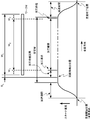
- FIG. 3 is a diagram for explaining scanning of the laser beam scanner of the pulse laser processing apparatus according to the present embodiment.
- the position range corresponding to the scan end position from the scan start position in the scan angle range of the scan mirror includes an acceleration period, a stable region, and a deceleration period.
- the apparatus is configured to control the scanning speed V to be constant within a stable range including the actual processing range.
- the XY stage unit 20 can place the workpiece W and can freely move in the XY direction including the direction orthogonal to the one-dimensional direction in which the pulse laser beam is scanned, its drive mechanism unit, and the XY stage.
- a position sensor having a laser interferometer for measuring the position is provided.
- the XY stage can be moved continuously or stepped in a two-dimensional wide range, for example, a distance range in the X direction and Y direction of about 1 m. And it is comprised so that the positioning accuracy and movement error may become the high precision of the range of a submicron.
- the processing control unit 24 is configured by hardware such as a microcomputer (MCU), a microprocessor (MPU), a digital signal processor (DSP), a semiconductor memory, a circuit board, or the like including a semiconductor integrated circuit, or a combination of these hardware and software. It is configured. Integrated control of processing by pulse laser processing equipment.
- MCU microcomputer
- MPU microprocessor
- DSP digital signal processor
- semiconductor memory a circuit board, or the like including a semiconductor integrated circuit, or a combination of these hardware and software. It is configured. Integrated control of processing by pulse laser processing equipment.
- FIG. 4 is an explanatory diagram of a machining control unit of the pulse laser machining apparatus according to the present embodiment.
- the processing control unit 24 includes a laser system / beam scanning system control unit 36, a processing data setting unit 38, and a processing pattern generation unit 40.
- the laser system / beam scanning system control unit 36 controls a laser system such as the laser oscillator 12 and the pulse picker 14 and a beam scanning system such as the laser beam scanner 18.
- the laser system / beam scanning system control unit 36 generates a laser / beam condition setting unit 68 for setting conditions of the laser system and the beam scanning system, and a clock signal S1 for maintaining synchronization of the laser system and the beam scanning system.
- a reference clock oscillation circuit 26 is provided.
- a phase synchronization processing circuit 42, a laser beam scanner control circuit 32, a synchronization position setting unit 44, a synchronization detection circuit 46, and the like are provided.
- machining data input from the outside to the machining data setting unit 40 is converted into parameter data in accordance with actual machining.
- the machining data input to the machining data setting unit 40 includes, for example, designation of a three-dimensional shape, dimensions, number of shapes, arrangement, workpiece material name, workpiece dimensions, and the like.
- FIG. 5 is an explanatory diagram of a machining pattern generation unit of the pulse laser machining apparatus according to the present embodiment.
- the machining pattern generation unit 40 includes a machining data analysis unit 48 that analyzes machining data input to the machining data setting unit 38.
- a table generation unit 49 that generates a processing table and a stage movement table based on the analysis by the processing data analysis unit 48 is provided.
- the processing table describes the standby length, processing length and non-processing length of the processing pattern based on the number of light pulses of the pulse laser beam. That is, the table generation unit 49 generates a processing table based on the processing length and non-processing length of the processing data and the spot diameter of the pulse laser beam.
- the stage movement table describes the movement distance of the XY stage unit and the like for the processing pattern.
- the processing pattern generation unit 40 includes a pulse picker processing table unit 50 including a processing table. Moreover, the stage movement table part 52 provided with a stage movement table is provided. Note that the processing table and the stage movement table are generated outside the processing pattern generation unit 40 and the pulse laser processing apparatus 10 even if the apparatus configuration is generated inside the processing pattern generation unit 40 as described above. It may be a device configuration.
- the machining pattern generation unit 40 includes a machining origin (SYNC) register 54 (hereinafter also simply referred to as a machining origin register) to which information on the machining origin output from the pulse picker machining table unit 50 is input. Further, a standby length output from the pulse picker processing table unit 50, a standby length register 56 to which information on processing length and non-processing length is input, a processing length register 58, and a non-processing length register 60 are provided.
- SYNC machining origin
- the values of the machining origin register 54, the standby length register 56, the machining length register 58, and the non-machining length register 60 are input to the machining pattern signal generation unit 62 and sent to the pulse picker control unit 22.
- the movement signal generation unit 64 is configured to generate a stage movement signal S15 based on the data from the stage movement table unit 52 and output it to the stage control unit 66.
- the data generated by the machining pattern generation unit 40 is also output to the laser system / beam scanning system control unit 36 and used to maintain synchronization between the laser system and the beam scanning system.
- FIG. 6 is an explanatory diagram of a machining pattern signal generation unit of the pulse laser machining apparatus according to the present embodiment.
- the machining pattern signal generation unit 62 includes a machining origin counter 70, a standby length counter 72, a machining length counter 74, and a non-machining length counter 76. These counters are configured to start counting in response to a counter control signal S8 output from the timing forming circuit 88.
- machining origin comparator 80 a standby length comparator 82, a machining length comparator 84, and a non-machining length comparator 86 having a function of comparing values of the register and the counter are provided. These comparators are configured to output coincidence signals a to d to the timing forming circuit 88 when the values of the register and the counter coincide.
- the timing formation circuit 88 is configured to output an output control signal S10 to the machining pattern output circuit 90 based on the input synchronization detection signal S9, the coincidence signals a to d, and the scanning end code.
- the machining pattern output circuit 90 is configured to generate a machining pattern signal S7 based on the output from the machining length comparator 84 and the output control signal S10 from the timing forming circuit 88.
- the processing control unit 24 generates an oscillator clock (clock signal) S1 to be given to the laser oscillator 12 based on the repetition frequency input data of the pulse laser beam in the reference clock oscillation circuit.
- the laser oscillator 12 generates a pulsed laser beam based on the oscillator clock S1. That is, a pulse laser beam synchronized with the clock signal is emitted.
- the pulsed laser beam PL1 is emitted by opening the built-in shutter. In this way, when the pulsed laser beam PL1 is emitted, there is no first pulse, and stable output energy is maintained.
- the machining control unit 24 generates a machining pattern signal S7 from the above-described two-dimensional machining data. Then, the pulse picker controller 22 supplies the pulse picker 14 with a pulse picker drive signal S6 that ensures synchronization with the pulse laser beam PL1 by the clock signal S1 in accordance with the machining pattern signal S7. Thus, in synchronization with the clock signal S1, the pulse picker 14 switches between passing and blocking of the pulse laser beam.
- the processing control unit 24 generates a scan command signal S2 that ensures synchronization with the clock signal S1 when the laser beam scanner 18 starts scanning. Then, the laser beam scanner controller 32 of the laser beam scanner 18 receives the scanning command signal S2 and controls the driving of the laser beam scanner 18. In this way, in synchronization with the clock signal, the laser beam scanner 18 scans the pulse laser beam only in the one-dimensional direction.
- the processing control unit 24 determines the movement timing of the XY stage unit 20 based on the scanning angle signal S5 that is a scanning position signal from the laser beam scanner 18, and the stage is determined based on the two-dimensional processing data and the movement timing.
- a movement signal S15 is generated.
- the scanning angle signal S5 in this case is from the scanning angle detection signal S4 in which the scanning end sensor 36 detects the processing end position at which the processing described in FIG. 3 ends or the scanning end position at which the scanner scan ends.
- the XY stage unit 20 operates in response to the stage movement signal S15.
- the XY stage is controlled to move in a direction orthogonal to the scanning direction of the laser beam scanner, for example, based on the scanning position signal of the laser beam scanner.
- the time to the next scanning is shortened, and further high speed of laser beam processing is realized.
- the processing control unit 24 may also control the beam shaper 16. This case is particularly effective when the beam shaper 16 automatically controls the beam diameter or automatically adjusts the light intensity distribution of the beam cross section.
- the laser oscillator 12 operates autonomously with most of the laser oscillation controlled by a built-in control unit.
- the reference clock oscillation circuit 26 controls the pulse oscillation timing and the like. This will be described with reference to FIG.
- the uniaxial scanning mirror 28 of the galvanometer scanner shown in FIG. 2 starts scanning at the scanning start position (scanning origin) as described with reference to FIG.
- the laser beam scanner 18 receives an instruction from a scan command signal S2 synchronized with, for example, rising (or falling) of the clock signal S1, and the laser beam scanner control unit 32 Drive control of the galvanometer 30 is performed.
- the laser beam scanner controller 32 controls the drive of the galvanometer 30 by the scanning command signal S2 so that the scanner speed becomes a stable scanning speed V at an early stage.
- the reproducibility of the scanning angle of the uniaxial scanning mirror 28 under the optimum condition is obtained empirically about 10 ⁇ rad / pp in the stable region. This value becomes a scanning position reproducibility of 1 ⁇ m / pp when an f ⁇ lens having a focal length of 100 mm is used.
- the repetitive stability in the acceleration period is deteriorated to about 10 times in the long-term scanning, so that the processing start position varies for each scanning. Therefore, the processing origin position for each scan is corrected by the correction mechanism based on the scanning position signal (scanning angle signal S5) from the laser beam scanner.
- the scanning angle range is about 2.3 degrees or more.
- the scan angle sensor 36 detects a preset synchronization angle ( ⁇ sy) as a detection signal as shown in FIG. 7B, the scan command signal ( ⁇ o: The difference from the scanning start position) is defined as a phase difference ( ⁇ i), and the distance to the processing origin with respect to the scanning command signal S2 is corrected based on this phase difference.
- the difference between the phase difference ( ⁇ n) and the phase difference ( ⁇ 1) is used as a distance correction value to the processing origin for the scan command signal for the first scan of the n-th scan, and the processing during the first scan and the n-th scan Match the origin position.
- the machining pattern signal S7 shown in FIG. 8 is given from a three-dimensional bitmap including distance data from the machining origin. For this reason, when the processing origin position matches for each scan, the processing start position of the processing pattern signal S7 also matches, and the pulse picker drive signal S6 is also generated at a desired timing.
- the scanner clock signal drives the servo control motor as a drive signal from the laser beam scanner control unit 32.
- the laser beam scanner 18 may have a phase shift due to its autonomous operation. Therefore, the synchronization angle detection signal that becomes the scanning position signal generated every time the scanning operation is repeated synchronizes the passage / blocking of the oscillation pulse light with the scanning operation of the beam, that is, the timing is adjusted, so that the laser is extremely stable. Processing becomes possible.
- the correction mechanism controls passage and blocking of the pulse laser beam in the pulse picker based on the scanning position signal (scanning angle signal S5). That is, the timing of the drive signal of the pulse picker 14 is designated based on the phase difference detected from the scanning position signal for detecting the synchronous position (angle) of the rotational position of the scanning mirror. Thereby, the processing origin position for each scan of the pulse laser beam is corrected.
- the correction mechanism gives a distance correction value obtained from the phase difference detected from the scanning position signal to the scanning command signal after the scanning command signal to the laser beam scanner for ⁇ o at the scanning angle from the scanning start position.
- the processing origin position for each scan of the pulse laser beam is corrected.
- the pulse laser beam is pulse-frequency modulated by the pulse picker operation to generate the required modulated pulse light. This will be described with reference to FIG.
- the pulse laser beam PL1 delayed by t1 from the clock signal S1 having the frequency Tp is cut off / passed by the pulse picker drive signal S6.
- the pulse picker drive signal S6 samples the processing pattern signal S7 at the rising edge of the clock signal S1, rises delayed by t2 from the rising edge of one clock of the clock signal S1, and starts from the rising edge of the other clock after the required number of clocks.
- the pattern signal falls after a delay of t3.
- the operation of the pulse picker 14 is generated according to the delay times t4 and t5 by this pulse picker driving signal, and the pulse laser beam PL1 during the operation is extracted as the modulated pulse laser beam PL2.
- the delay times t2, t3, t4 and t5 are set in accordance with the pulse picker.
- the inverted pattern signal of the pulse picker driving signal S6 becomes a driver signal that controls ON / OFF of oscillation in the ultrasonic wave generation control unit. Then, the required oscillation pulse light is extracted by the driver signal having the inverted pattern.
- AOM acousto-optic device
- the scanning position signal (scanning angle signal S5) from the laser beam scanner 18, for example, the scanning position signal of the processing end position at the rotational position of the scanning mirror is the moving timing of the XY stage moving unit 20. Instruct. Assuming that the one-dimensional scanning direction of the laser beam scanner 18 is the X-axis direction, step movement or continuous movement of a predetermined width in the Y-axis direction is performed according to the movement timing. Alternatively, continuous movement or step movement of a predetermined distance in the X-axis direction of the XY stage is performed. In this way, movement control of a predetermined movement pattern of the XY stage is performed.
- each pulse light is shaped into a required shape by the beam shaper 16. Then, by the scanning in the X-axis direction by the laser beam scanner 18 and the movement of the workpiece W position in the Y-axis direction by the XY stage unit 20, the irradiation pulse light is projected to the required position of the workpiece W, and the height of the surface of the workpiece W is increased. Precision micromachining is performed.
- the time width of each pulse picker operation and the time interval of each operation in the pulse picker operation pattern may be different from each other.
- a pulse laser processing method using the pulse laser processing apparatus 10 will be described.
- a workpiece (work) is placed on a stage, a clock signal is generated, a pulse laser beam synchronized with the clock signal is emitted, and the surface of the workpiece is synchronized with the clock signal.
- the pulse laser beam is scanned in one dimension, the pulse laser beam is scanned in one dimension, the stage is moved in the direction orthogonal to the one dimension, and the pulse laser beam is further synchronized with the clock signal.
- Is a pulse laser processing method of scanning in the one-dimensional direction When the pulse laser beam is scanned in the one-dimensional direction, the irradiation of the pulse laser beam and the non-irradiation are switched in synchronization with the clock signal based on the number of light pulses of the pulse laser beam.
- FIG. 7 is a signal waveform diagram illustrating timing control of the pulse laser processing apparatus according to the present embodiment.
- the laser oscillator 12 operates autonomously with the majority of laser oscillation controlled by a built-in control unit.
- the pulse oscillation timing is controlled by the clock signal S1 having the period Tp generated by the reference clock oscillation circuit, and the pulse laser beam PL1 having the period Tp synchronized with the clock signal S1. Is emitted.
- the laser beam scanner 18 starts scanning at the scanning start position (scanning origin) shown in FIG. 6 based on the scanning start signal S11. At this time, as shown in FIG. 7A, the laser beam scanner 18 is instructed by a scan command signal S2 having a cycle Ts generated by the processing control unit 24 in synchronization with the rising edge (or falling edge) of the clock signal S1. Receive.
- the laser beam scanner control unit 32 controls driving of the galvanometer 30 based on the scanning command signal S2.
- the laser beam scanner 18 scans the pulse laser beam in a one-dimensional direction in synchronization with the clock signal S1. At this time, a pattern is processed on the surface of the workpiece W by switching between irradiation and non-irradiation of the pulse laser beam.
- An example of the scan command signal S2 synchronized with the rising edge of S1 is shown.
- the stage After scanning the pulse laser beam in the one-dimensional direction, the stage is moved in the direction orthogonal to the one-dimensional direction, and the pulse laser beam is scanned in the one-dimensional direction in synchronization with the clock signal. In this way, the scanning of the pulse laser beam in the one-dimensional direction and the movement of the stage are alternately performed in the direction orthogonal to the one-dimensional direction.
- the scanning angle signal S5 which is a scanning position signal from the laser beam scanner 18, indicates the movement timing of the XY stage unit. Assuming that the one-dimensional scanning direction of the laser beam scanner 18 is the X-axis direction, step movement or continuous movement of a predetermined width in the Y-axis direction is performed according to the movement timing. Thereafter, the pulse laser beam is scanned in the X direction.
- the laser beam scanner 18 is controlled by the scanning command signal S2 so that the scanning speed becomes a stable scanning speed V at an early stage. It is empirically clear that the reproducibility of the scanning angle of the single-axis scanning mirror 28 under the optimum condition is about 10 ⁇ rad / pp in the stable region. This value becomes a scanning position reproducibility of 1 ⁇ m / pp when an f ⁇ lens having a focal length of 100 mm is used.
- a synchronization angle ( ⁇ sy) for synchronizing the oscillation of the pulse laser beam PL1 and the beam scanning is set in a sufficiently stable region after the end of the acceleration period.
- the scanning angle range to reach a sufficiently stable region is, for example, about 2.3 degrees to 3.4 degrees when an f ⁇ lens having an acceleration period of 1 msec to 1.5 msec and a focal length of 100 mm is used.
- the scanning angle sensor 36 detects this synchronization angle. Then, a phase difference ⁇ i between the scan command signal S2 corresponding to the scanning angle theta 0 from the scanning start position in detecting the synchronization angle. Then, based on this phase difference ⁇ i , the distance to the processing origin with respect to the scanning command signal S2 is corrected.
- the distance correction value to the origin is used.
- the stage is moved in the direction orthogonal to the one-dimensional direction, and the pulse laser beam is further moved in the one-dimensional direction in synchronization with the clock signal S1.
- the machining origin position for each scan is matched, and the machining accuracy is improved.
- the pulse laser beam is switched between irradiation and non-irradiation in synchronization with the clock signal S1 based on the number of light pulses of the pulse laser beam. Irradiation and non-irradiation of the pulse laser beam are performed using a pulse picker.
- Machining origin synchronous angle detection position + S L + W 1
- SYNC machining origin
- the processing origin (SYNC) is managed by performing the correction as described above, and processing is always started from a stable position for each scan. Note that, as shown in FIG. 3, the actual machining is performed in a range that falls within the machining range (W 2 ).
- the pulse picker drive signal S6 created by the pulse picker defines the actual processing area by the processing length, and the repetitive processing pitch by the non-processing length.
- the start position for each machining shape is set by defining the position where machining is actually started from the machining origin (SYNC) as the standby length.
- SYNC machining origin
- Processing origin (SYNC) number of light pulses (S L + W 1 ) / (D / n)
- the set values in each register for the machining length, non-machining length, standby length, and machining origin (SYNC) are the number of optical pulses corresponding to each.
- the number of light pulses is a value that takes into account the number of light pulses for correction determined in advance based on the beam profile to be used.
- the above register setting values are managed by the number of light pulses to be emitted. Further, the processing standby section after the synchronization angle detection is also managed by the number of light pulses. By managing the pulse picker by the number of optical pulses in this way, synchronization between the reference clock signal S1 and the pulse picker can be easily maintained, and stable repeatability is maintained. By maintaining the synchronization between the clock signal S1 and the pulse picker 14, highly accurate laser processing can be easily realized.
- FIG. 8 is a signal waveform diagram illustrating timing control of the pulse picker operation of the pulse laser processing apparatus according to the present embodiment.
- the machining pattern signal S7 generated from the machining data and managed by the number of light pulses is output from the machining pattern output circuit 62 of the machining pattern signal generation unit 40.
- the pulsed laser beam was t 1 delayed from the clock signal S1 periods Tp (PL1) is cut off / passage is controlled based on the pulse picker drive signal S6.
- the scanning of the laser beam scanner 18 is synchronized with the blocking / passing of the pulse laser beam by synchronizing the generation timing of the scanning angle command signal (S2) with the clock signal (S1).
- the pulse picker driving signal S6 samples the processing pattern signal S7 at the rising edge of the clock signal S1. Then, it rises with a delay from the rise of one clock of the clock signal S1 t 2 hours. After the number of clocks corresponding to the number of desired pulses, the state of machining pattern signal S7 becomes inactive sampled at the rising edge of the clock signal S1, it falls with a delay t 3 hours.
- the pulse picker driving signal S6 the operation of the pulse pickers 14 occurs after a delay time t 4 and t 5 elapses.
- the pulse laser beam (PL1) is extracted as a modulated pulse laser beam (PL2).
- the machining data includes, for example, designation of a three-dimensional shape, dimensions, the number of shapes, arrangement positions, workpiece material names, workpiece dimensions, and the like.
- the machining data is analyzed by the machining data analysis unit 48 of the machining pattern generation unit 40.
- the processing amount of the unit light pulse can be obtained empirically from conditions such as the operation of the laser oscillator used for processing, the irradiation pulse energy, which is the beam scanning condition, the beam spot diameter, the repetition frequency, the scanning speed, and the stage feed amount .
- the 3D shape is further decomposed into 2D layers and converted into 2D data using bitmap data for each layer.
- This two-dimensional data is converted into operation data (number of machining pulses, number of non-machining pulses, number of standby length pulses) of the pulse picker 14.
- the number of layers decomposed in this way is referred to as a layer number Rn.
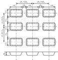
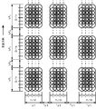
- FIG. 9 is a diagram showing an example of processing by the pulse laser processing apparatus of the embodiment.
- FIG. 10 is a diagram showing scanning in a specific one-dimensional direction in the processing of FIG.
- FIG. 11 is a diagram showing two-dimensional processing for a specific layer in the processing of FIG.
- LX 1 horizontal
- LY 1 vertical
- Dp depth
- the machining direction of LX 1 and the non-machining length of LX 2 are performed in the X direction that is the beam scanning direction, and the machining length of LY 1 is performed in the Y direction that is the stage moving direction. 2. Processing of non-processed length of LY 3 is performed.
- FIG. 10 shows one-dimensional scanning of one line in the region corresponding to LY 1 in the Y direction.
- the number of light pulses is (S L + W 1 ) / (D / n) Lw based on the processing origin (SYNC) separated by (D / n), and the number of light pulses is L W / (D /
- the workpiece is irradiated with a pulsed laser beam with a waiting length of n). This irradiation is (LX 1 / (D / n)) ⁇ 1 in terms of the number of light pulses. Thereafter, the number of light pulses is not irradiated for (LX 2 / (D / n)) + 1, and irradiation and non-irradiation controlled by the number of light pulses are repeated in the same scan.
- the stage is moved in the Y direction orthogonal to the X direction, and further the X direction scan is performed by the laser beam scanner 18. I do. That is, the workpiece is processed by alternately repeating the scanning in the one-dimensional direction of the pulse laser beam by the laser beam scanner 18 and the movement of the stage in the direction orthogonal to the one-dimensional direction following the scanning.
- the operation of the machining control unit 24 will be described in detail with reference to FIGS. 5 and 6.
- the table is sent to the pulse picker machining table unit 50.
- the selection signal S13 “machining origin (SYNC)” is output.
- information on the machining origin is output from the pulse picker machining table unit 50 and loaded into the machining origin register 54.
- the machining origin (SYNC) counter 70 (hereinafter also simply referred to as a machining origin counter) starts counting the clock signal S1.
- the comparator control signal S14 enables a machining origin (SYNC) comparator 80 (hereinafter also simply referred to as a machining origin comparator), and compares the value of the machining origin counter 70 with the value of the machining origin register 54. When they match, the machining origin comparator 80 outputs a coincidence signal a to the timing forming circuit 88. At this time, the pulse laser beam is scanned to the processing origin position.
- SYNC machining origin
- the timing forming circuit 88 outputs a counter control signal S8 and stops the counting of the machining origin counter 70. Then, the table selection signal S13 “standby length” is output from the timing forming circuit 88 to the pulse picker processing table unit 50. Standby length information is output from the pulse picker processing table section 50 and loaded into the standby length register 56. At the same time, the standby length counter 72 starts counting the clock signal S1 by the counter control signal S8.
- the comparator control signal S14 enables the standby length comparator 82 and compares the value of the standby length counter 72 with the value of the standby length register 56. If they match, the standby length comparator 82 outputs a match signal b to the timing forming circuit 88. At this time, the pulse laser beam is scanned to the actual machining start position.
- the timing forming circuit 88 outputs a counter control signal S8 and stops the counting of the standby length counter 72. Then, the table selection signal S13 “machining length” is output from the timing forming circuit 88 to the pulse picker machining table unit 50. Processing length information is output from the pulse picker processing table unit 50 and loaded into the processing length register 58. At the same time, the machining length counter 74 starts counting the clock signal S1 by the counter control signal S8.
- the comparator control signal S14 enables the machining length comparator 84, and compares the value of the machining length counter 74 with the value of the machining length register 58. When they match, the machining length comparator 84 outputs a coincidence signal c to the timing forming circuit 88. At this time, the pulsed laser beam is scanned to the position where the processing is completed.
- the timing forming circuit 88 outputs a counter control signal S8, and stops the counting of the machining length counter 74. Then, the table selection signal S13 “non-processing length” is output from the timing forming circuit 88 to the pulse picker processing table unit 50. Information on the non-machining length is output from the pulse picker machining table unit 50 and loaded into the non-machining length register 60. At the same time, the non-machining length counter 76 starts counting the clock signal S1 by the counter control signal S8.
- the comparator control signal S14 enables the non-machining length comparator 86 and compares the value of the non-machining length counter 76 with the value of the non-machining length register 60. When they match, the non-machining length comparator 86 outputs a coincidence signal d to the timing forming circuit 88. At this time, the pulse laser beam is scanned to the non-processed end. Then, scanning is performed up to one light pulse before the position at which actual machining is started.
- the timing forming circuit 88 outputs a counter control signal S8 and stops the counting of the non-machining length counter 76. Then, the table selection signal S13 “machining length” is output from the timing forming circuit 88 to the pulse picker machining table unit 50. Processing length information is output from the pulse picker processing table unit 50 and loaded into the processing length register 58. At the same time, the machining length counter 74 starts counting the clock signal S1 by the counter control signal S8.
- the comparator control signal S14 enables the machining length comparator 84, and compares the value of the machining length counter 74 with the value of the machining length register 58. When they match, the machining length comparator 84 outputs a coincidence signal c to the timing forming circuit 88. At this time, the pulsed laser beam is scanned to the position where the processing is completed.
- the timing forming circuit 88 outputs a counter control signal S8, and stops the counting of the machining length counter 74. Then, the table selection signal S13 “non-processing length” is output from the timing forming circuit 88 to the pulse picker processing table unit 50. Information on the non-machining length is output from the pulse picker machining table unit 50 and loaded into the non-machining length register 60. At the same time, the non-machining length counter 76 starts counting the clock signal S1 by the counter control signal S8.
- the comparator control signal S14 enables the non-machining length comparator 86 and compares the value of the non-machining length counter 76 with the value of the non-machining length register 60. When they match, the non-machining length comparator 86 outputs a coincidence signal d to the timing forming circuit 88. At this time, the pulse laser beam is scanned to the non-processed end. Then, scanning is performed up to one light pulse before the position at which actual machining is started.
- the machining pattern output circuit 90 recognizes the machining execution period according to the output of the machining length comparator 84, and further outputs the machining pattern signal S7 by the output control signal S10 from the timing forming circuit 88.
- the timing control of the pulse picker operation based on the machining pattern signal S7 is as shown in FIG.
- the processing pattern generation unit 40 performs one-dimensional scanning of a pulse laser beam as shown in FIG. 10 according to the pulse picker processing table provided in the pulse picker processing table unit 50.
- the pulse picker processing table unit 50 is provided with a scanning end code, and is output to the timing forming circuit 88 after the end of the specific beam scanning.
- stage movement is performed, the stage movement amount is read from the stage movement table unit 52, and the stage movement amount and stage movement are transferred from the movement signal generation unit 64 to the stage control unit 66.
- a stage movement signal S15 including a start command is output.
- the next line beam scan is started. Processing by one-dimensional beam scanning is performed according to the same process as described above. When the predetermined number of beam scans and stage movements are finished, the processing of the two-dimensional layer is finished.
- Determination of the processing end of the two-dimensional layer is performed based on the movement end code provided in the stage movement table unit 52.
- the stage is controlled to move to the first line.
- beam scanning and stage movement are performed according to the data of the “pulse picker processing table” and “stage movement table”, and processing of each layer is executed. Then, a predetermined number of layers given by Rn is processed.
- Table 1 is an example of the table of the embodiment.
- Table 1 is an example in which the pulse picker processing table and the stage movement table are described in the same table.
- the standby length, processing length, and non-processing length are described in terms of the number of light pulses. Note that the pulse picker processing table and the stage movement table may exist as separate tables.
- the present embodiment is a microlens mold manufacturing method using the pulse laser processing apparatus and pulse laser processing method of the first embodiment, a microlens mold manufactured using the same, and this This is a method of manufacturing a microlens using a microlens mold.
- FIG. 12 shows an example of processing a mold formed by the manufacturing method of the present embodiment.
- dimples having a diameter R and a depth Dp are formed at nine locations with a spacing I on a Cu workpiece.
- Laser processing is performed in the same manner as in the first embodiment.
- the processing table By using a table conforming to the three-dimensional shape of FIG. 12 as the processing table, the processing of FIG. 12 can be realized. According to the present embodiment, it is possible to manufacture a microlens mold having a large area and high accuracy.
- this microlens mold is useful for producing a large area and high precision microlens. According to the microlens manufacturing method using this microlens mold, it is possible to manufacture a large-area and high-precision microlens.
- the present invention is not limited to these shapes.
- a cone shape for manufacturing a rib for electronic paper a triangular pyramid, a square shape, or the like. It may be a pulse laser processing apparatus or a pulse laser processing method for processing an arbitrary shape such as a weight, a V groove, a concave groove, an R groove, or a combination thereof.
- Cu material was mainly demonstrated to the example as a to-be-processed object, even if it is other materials, such as metal materials, such as Ni material and SKD11, DLC material, a polymer material, a semiconductor material, a glass material, for example, I do not care.
- metal materials such as Ni material and SKD11, DLC material, a polymer material, a semiconductor material, a glass material, for example, I do not care.
- the laser oscillator is not limited to the YAG laser, but is a single wavelength band laser such as a second harmonic (wavelength: 532 nm) of other Nd: YVO 4 laser suitable for processing a workpiece. Or you may output a multiple wavelength band laser.
Landscapes
- Physics & Mathematics (AREA)
- Optics & Photonics (AREA)
- Engineering & Computer Science (AREA)
- Plasma & Fusion (AREA)
- Mechanical Engineering (AREA)
- General Physics & Mathematics (AREA)
- Laser Beam Processing (AREA)
- Mechanical Optical Scanning Systems (AREA)
Priority Applications (3)
| Application Number | Priority Date | Filing Date | Title |
|---|---|---|---|
| EP10806178.9A EP2463051A4 (de) | 2009-08-03 | 2010-06-24 | Impulslaserbearbeitungsvorrichtung und impulslaserbearbeitungsverfahren |
| JP2010541620A JP5148717B2 (ja) | 2009-08-03 | 2010-06-24 | パルスレーザ加工装置およびパルスレーザ加工方法 |
| US13/388,508 US8933374B2 (en) | 2009-08-03 | 2010-06-24 | Pulse laser machining apparatus and pulse laser machining method |
Applications Claiming Priority (2)
| Application Number | Priority Date | Filing Date | Title |
|---|---|---|---|
| JP2009180285 | 2009-08-03 | ||
| JP2009-180285 | 2009-08-03 |
Publications (1)
| Publication Number | Publication Date |
|---|---|
| WO2011016176A1 true WO2011016176A1 (ja) | 2011-02-10 |
Family
ID=43544090
Family Applications (1)
| Application Number | Title | Priority Date | Filing Date |
|---|---|---|---|
| PCT/JP2010/004197 Ceased WO2011016176A1 (ja) | 2009-08-03 | 2010-06-24 | パルスレーザ加工装置およびパルスレーザ加工方法 |
Country Status (4)
| Country | Link |
|---|---|
| US (1) | US8933374B2 (de) |
| EP (1) | EP2463051A4 (de) |
| JP (1) | JP5148717B2 (de) |
| WO (1) | WO2011016176A1 (de) |
Cited By (6)
| Publication number | Priority date | Publication date | Assignee | Title |
|---|---|---|---|---|
| JP2013091074A (ja) * | 2011-10-25 | 2013-05-16 | Toshiba Mach Co Ltd | パルスレーザ加工装置およびパルスレーザ加工方法 |
| JP2013121603A (ja) * | 2011-11-10 | 2013-06-20 | Toshiba Mach Co Ltd | パルスレーザ加工装置およびパルスレーザ加工方法 |
| JP2015223628A (ja) * | 2014-05-30 | 2015-12-14 | ビアメカニクス株式会社 | レーザ加工装置及びレーザ加工方法 |
| CN105935841A (zh) * | 2015-03-06 | 2016-09-14 | 住友重机械工业株式会社 | 激光加工装置 |
| JP2018045254A (ja) * | 2017-12-11 | 2018-03-22 | 株式会社ニコン | パターン描画装置 |
| CN110455233A (zh) * | 2019-08-08 | 2019-11-15 | 广合科技(广州)有限公司 | 一种pcb激光钻孔精度测试装置及方法 |
Families Citing this family (12)
| Publication number | Priority date | Publication date | Assignee | Title |
|---|---|---|---|---|
| JP4612733B2 (ja) * | 2008-12-24 | 2011-01-12 | 東芝機械株式会社 | パルスレーザ加工装置 |
| EP2463051A4 (de) * | 2009-08-03 | 2017-06-14 | Toshiba Kikai Kabushiki Kaisha | Impulslaserbearbeitungsvorrichtung und impulslaserbearbeitungsverfahren |
| JP5091287B2 (ja) * | 2010-08-06 | 2012-12-05 | ファナック株式会社 | 加工点にエネルギー又は物質を供給する加工機における加工情報取得装置 |
| EP3045257B1 (de) * | 2015-01-13 | 2018-05-16 | Berner Fachhochschule Wissens- und Technologietransfer (WTT) | Verfahren und vorrichtung zur laserverarbeitung |
| JP6817716B2 (ja) * | 2015-09-03 | 2021-01-20 | ビアメカニクス株式会社 | レーザ加工装置及びレーザ加工方法 |
| KR102384586B1 (ko) * | 2016-08-28 | 2022-04-11 | 에이씨에스 모션 컨트롤 리미티드 | 비교적 큰 가공물을 가공하는 레이저를 위한 방법 및 시스템 |
| EP3526635B1 (de) * | 2016-10-11 | 2022-06-08 | Caliber Imaging & Diagnostics, Inc. | Resonanzscanner-interoperation mit beweglicher stufe |
| KR101973512B1 (ko) * | 2017-02-14 | 2019-04-30 | 씨에스캠 주식회사 | 3차원 대면적 레이저 연속 가공 장치 |
| US20180339364A1 (en) * | 2017-05-29 | 2018-11-29 | ACS Motion Control Ltd. | System and method for machining of relatively large work pieces |
| WO2020198553A1 (en) * | 2019-03-28 | 2020-10-01 | Panasonic intellectual property Management co., Ltd | Material processing utilizing high-frequency beam shaping |
| CN112091210A (zh) * | 2019-06-17 | 2020-12-18 | 广东汉邦激光科技有限公司 | 3d激光成型装置及3d激光成型方法 |
| DE102019125103A1 (de) * | 2019-09-18 | 2021-03-18 | Bystronic Laser Ag | Bearbeitungsvorrichtung zur Laserbearbeitung eines Werkstücks, Verfahren zur Laserbearbeitung eines Werkstücks |
Citations (4)
| Publication number | Priority date | Publication date | Assignee | Title |
|---|---|---|---|---|
| JP2001042246A (ja) * | 1999-07-28 | 2001-02-16 | Nec Corp | 光学スキャナ装置 |
| JP2002530204A (ja) * | 1998-11-20 | 2002-09-17 | ミネソタ マイニング アンド マニュファクチャリング カンパニー | レーザーアブレーションによる特徴部形成のためのマスク軌道 |
| JP2002536188A (ja) * | 1999-02-10 | 2002-10-29 | エレクトロ サイエンティフィック インダストリーズ インコーポレーテッド | レーザ処理パワー出力安定化 |
| JP2005118814A (ja) * | 2003-10-16 | 2005-05-12 | Hitachi Via Mechanics Ltd | レーザ加工方法およびレーザ加工装置 |
Family Cites Families (29)
| Publication number | Priority date | Publication date | Assignee | Title |
|---|---|---|---|---|
| US3636251A (en) * | 1968-08-28 | 1972-01-18 | Quantronix Corp | Laser facsimile system for engraving printing plates |
| JPH0651913B2 (ja) * | 1988-04-22 | 1994-07-06 | 川崎製鉄株式会社 | 圧延用ロールの表面加工方法及びその装置並びに該方法により製造されるプレス加工用金属薄板とその製造方法 |
| JP3399590B2 (ja) * | 1993-08-04 | 2003-04-21 | 富士通株式会社 | 配線の切断装置 |
| US5751585A (en) * | 1995-03-20 | 1998-05-12 | Electro Scientific Industries, Inc. | High speed, high accuracy multi-stage tool positioning system |
| US5751588A (en) * | 1995-04-28 | 1998-05-12 | International Business Machines Corporation | Multi-wavelength programmable laser processing mechanisms and apparatus utilizing vaporization detection |
| US6373026B1 (en) * | 1996-07-31 | 2002-04-16 | Mitsubishi Denki Kabushiki Kaisha | Laser beam machining method for wiring board, laser beam machining apparatus for wiring board, and carbonic acid gas laser oscillator for machining wiring board |
| US7732732B2 (en) * | 1996-11-20 | 2010-06-08 | Ibiden Co., Ltd. | Laser machining apparatus, and apparatus and method for manufacturing a multilayered printed wiring board |
| JP4357749B2 (ja) * | 1999-04-27 | 2009-11-04 | 三菱電機株式会社 | レーザ加工機の加工条件設定装置 |
| US20030222324A1 (en) * | 2000-01-10 | 2003-12-04 | Yunlong Sun | Laser systems for passivation or link processing with a set of laser pulses |
| US6407363B2 (en) * | 2000-03-30 | 2002-06-18 | Electro Scientific Industries, Inc. | Laser system and method for single press micromachining of multilayer workpieces |
| JP3870693B2 (ja) | 2000-11-28 | 2007-01-24 | 三菱電機株式会社 | レーザ加工機 |
| US8497450B2 (en) * | 2001-02-16 | 2013-07-30 | Electro Scientific Industries, Inc. | On-the fly laser beam path dithering for enhancing throughput |
| US6639177B2 (en) * | 2001-03-29 | 2003-10-28 | Gsi Lumonics Corporation | Method and system for processing one or more microstructures of a multi-material device |
| US7569794B2 (en) * | 2001-05-23 | 2009-08-04 | Osmotica Corp. | Laser drilling system and method |
| KR100938325B1 (ko) * | 2001-06-13 | 2010-01-22 | 오르보테크 엘티디. | 에너지 전달 시스템 |
| GB0127410D0 (en) * | 2001-11-15 | 2002-01-09 | Renishaw Plc | Laser substrate treatment |
| JP2004128421A (ja) * | 2002-10-07 | 2004-04-22 | Semiconductor Energy Lab Co Ltd | レーザ照射方法およびレーザ照射装置、並びに半導体装置の作製方法 |
| JP2005118821A (ja) | 2003-10-16 | 2005-05-12 | Olympus Corp | 超短パルスレーザ加工方法 |
| EP1547719A3 (de) * | 2003-12-26 | 2009-01-28 | Semiconductor Energy Laboratory Co., Ltd. | Laserbestrahlungsvorrichtung, Laserbestrahlungsverfahren und Verfahren zur Herstellung eines kristallinen Halbleiterfilms |
| US7133186B2 (en) * | 2004-06-07 | 2006-11-07 | Electro Scientific Industries, Inc. | AOM modulation techniques employing transducers to modulate different axes |
| US20060102601A1 (en) * | 2004-11-12 | 2006-05-18 | The Regents Of The University Of California | Feedback controlled laser machining system |
| WO2007041460A2 (en) * | 2005-10-03 | 2007-04-12 | Aradigm Corporation | Method and system for laser machining |
| CN101611324B (zh) * | 2005-10-18 | 2012-11-21 | Gsi集团公司 | 利用光学基准的方法和器件 |
| JPWO2008053915A1 (ja) * | 2006-11-02 | 2010-02-25 | ナブテスコ株式会社 | スキャナ光学システム、レーザ加工装置、及び、スキャナ光学装置 |
| US7324861B1 (en) * | 2006-11-30 | 2008-01-29 | Chun Bin Zheng | Numerical control system and method for laser cutting SMT stencil |
| US8026158B2 (en) * | 2007-06-01 | 2011-09-27 | Electro Scientific Industries, Inc. | Systems and methods for processing semiconductor structures using laser pulses laterally distributed in a scanning window |
| US7982160B2 (en) * | 2008-03-31 | 2011-07-19 | Electro Scientific Industries, Inc. | Photonic clock stabilized laser comb processing |
| US8178818B2 (en) * | 2008-03-31 | 2012-05-15 | Electro Scientific Industries, Inc. | Photonic milling using dynamic beam arrays |
| EP2463051A4 (de) * | 2009-08-03 | 2017-06-14 | Toshiba Kikai Kabushiki Kaisha | Impulslaserbearbeitungsvorrichtung und impulslaserbearbeitungsverfahren |
-
2010
- 2010-06-24 EP EP10806178.9A patent/EP2463051A4/de not_active Withdrawn
- 2010-06-24 US US13/388,508 patent/US8933374B2/en active Active
- 2010-06-24 WO PCT/JP2010/004197 patent/WO2011016176A1/ja not_active Ceased
- 2010-06-24 JP JP2010541620A patent/JP5148717B2/ja active Active
Patent Citations (4)
| Publication number | Priority date | Publication date | Assignee | Title |
|---|---|---|---|---|
| JP2002530204A (ja) * | 1998-11-20 | 2002-09-17 | ミネソタ マイニング アンド マニュファクチャリング カンパニー | レーザーアブレーションによる特徴部形成のためのマスク軌道 |
| JP2002536188A (ja) * | 1999-02-10 | 2002-10-29 | エレクトロ サイエンティフィック インダストリーズ インコーポレーテッド | レーザ処理パワー出力安定化 |
| JP2001042246A (ja) * | 1999-07-28 | 2001-02-16 | Nec Corp | 光学スキャナ装置 |
| JP2005118814A (ja) * | 2003-10-16 | 2005-05-12 | Hitachi Via Mechanics Ltd | レーザ加工方法およびレーザ加工装置 |
Cited By (7)
| Publication number | Priority date | Publication date | Assignee | Title |
|---|---|---|---|---|
| JP2013091074A (ja) * | 2011-10-25 | 2013-05-16 | Toshiba Mach Co Ltd | パルスレーザ加工装置およびパルスレーザ加工方法 |
| JP2013121603A (ja) * | 2011-11-10 | 2013-06-20 | Toshiba Mach Co Ltd | パルスレーザ加工装置およびパルスレーザ加工方法 |
| JP2015223628A (ja) * | 2014-05-30 | 2015-12-14 | ビアメカニクス株式会社 | レーザ加工装置及びレーザ加工方法 |
| CN105935841A (zh) * | 2015-03-06 | 2016-09-14 | 住友重机械工业株式会社 | 激光加工装置 |
| JP2018045254A (ja) * | 2017-12-11 | 2018-03-22 | 株式会社ニコン | パターン描画装置 |
| CN110455233A (zh) * | 2019-08-08 | 2019-11-15 | 广合科技(广州)有限公司 | 一种pcb激光钻孔精度测试装置及方法 |
| CN110455233B (zh) * | 2019-08-08 | 2024-06-04 | 广州广合科技股份有限公司 | 一种pcb激光钻孔精度测试装置及方法 |
Also Published As
| Publication number | Publication date |
|---|---|
| EP2463051A1 (de) | 2012-06-13 |
| US8933374B2 (en) | 2015-01-13 |
| JPWO2011016176A1 (ja) | 2013-01-10 |
| US20120187103A1 (en) | 2012-07-26 |
| EP2463051A4 (de) | 2017-06-14 |
| JP5148717B2 (ja) | 2013-02-20 |
Similar Documents
| Publication | Publication Date | Title |
|---|---|---|
| JP5148717B2 (ja) | パルスレーザ加工装置およびパルスレーザ加工方法 | |
| JP4612733B2 (ja) | パルスレーザ加工装置 | |
| JP5132726B2 (ja) | パルスレーザ加工装置およびパルスレーザ加工方法 | |
| JP5634765B2 (ja) | パルスレーザ加工方法およびパルスレーザ加工用データ作成方法 | |
| JP5981094B2 (ja) | ダイシング方法 | |
| JP5865671B2 (ja) | パルスレーザ加工装置 | |
| CN109570778B (zh) | 一种硬脆性材料的激光加工方法及激光加工系统 | |
| JP5498852B2 (ja) | パルスレーザ加工装置、シェーディング補正装置およびパルスレーザ加工方法 | |
| JP5452247B2 (ja) | レーザダイシング装置 | |
| JP5909352B2 (ja) | パルスレーザ加工装置およびパルスレーザ加工方法 | |
| JP6910086B1 (ja) | レーザ加工装置、レーザ加工システム、ローテータユニット装置、レーザ加工方法、及び、プローブカードの生産方法 | |
| JP5632662B2 (ja) | パルスレーザ加工方法 | |
| JPH11170072A (ja) | レーザー加工方法及び装置、並びに非導電性透明基板の回路形成方法及び装置 | |
| JP5901265B2 (ja) | パルスレーザ加工装置およびパルスレーザ加工方法 | |
| JP2017124416A (ja) | レーザ加工装置及びレーザ加工方法 | |
| JP5909351B2 (ja) | パルスレーザ加工装置およびパルスレーザ加工方法 | |
| TW202322952A (zh) | 雷射加工裝置、探針卡的生產方法和雷射加工方法 | |
| JP6759619B2 (ja) | 蒸着用メタルマスク加工方法及び蒸着用メタルマスク加工装置 | |
| JP7620302B2 (ja) | レーザ加工装置、及び、レーザ加工方法 | |
| JP2010194555A (ja) | レーザ加工装置及びレーザ加工方法 |
Legal Events
| Date | Code | Title | Description |
|---|---|---|---|
| ENP | Entry into the national phase |
Ref document number: 2010541620 Country of ref document: JP Kind code of ref document: A |
|
| 121 | Ep: the epo has been informed by wipo that ep was designated in this application |
Ref document number: 10806178 Country of ref document: EP Kind code of ref document: A1 |
|
| NENP | Non-entry into the national phase |
Ref country code: DE |
|
| WWE | Wipo information: entry into national phase |
Ref document number: 2010806178 Country of ref document: EP |
|
| WWE | Wipo information: entry into national phase |
Ref document number: 13388508 Country of ref document: US |