WO2011040545A1 - 糸巻取装置 - Google Patents
糸巻取装置 Download PDFInfo
- Publication number
- WO2011040545A1 WO2011040545A1 PCT/JP2010/067116 JP2010067116W WO2011040545A1 WO 2011040545 A1 WO2011040545 A1 WO 2011040545A1 JP 2010067116 W JP2010067116 W JP 2010067116W WO 2011040545 A1 WO2011040545 A1 WO 2011040545A1
- Authority
- WO
- WIPO (PCT)
- Prior art keywords
- yarn
- winding
- storage drum
- spun
- rotary storage
- Prior art date
- Legal status (The legal status is an assumption and is not a legal conclusion. Google has not performed a legal analysis and makes no representation as to the accuracy of the status listed.)
- Ceased
Links
Images



Classifications
-
- B—PERFORMING OPERATIONS; TRANSPORTING
- B65—CONVEYING; PACKING; STORING; HANDLING THIN OR FILAMENTARY MATERIAL
- B65H—HANDLING THIN OR FILAMENTARY MATERIAL, e.g. SHEETS, WEBS, CABLES
- B65H51/00—Forwarding filamentary material
- B65H51/20—Devices for temporarily storing filamentary material during forwarding, e.g. for buffer storage
- B65H51/22—Reels or cages, e.g. cylindrical, with storing and forwarding surfaces provided by rollers or bars
-
- B—PERFORMING OPERATIONS; TRANSPORTING
- B65—CONVEYING; PACKING; STORING; HANDLING THIN OR FILAMENTARY MATERIAL
- B65H—HANDLING THIN OR FILAMENTARY MATERIAL, e.g. SHEETS, WEBS, CABLES
- B65H67/00—Replacing or removing cores, receptacles, or completed packages at paying-out, winding, or depositing stations
- B65H67/08—Automatic end-finding and material-interconnecting arrangements
- B65H67/081—Automatic end-finding and material-interconnecting arrangements acting after interruption of the winding process, e.g. yarn breakage, yarn cut or package replacement
-
- B—PERFORMING OPERATIONS; TRANSPORTING
- B65—CONVEYING; PACKING; STORING; HANDLING THIN OR FILAMENTARY MATERIAL
- B65H—HANDLING THIN OR FILAMENTARY MATERIAL, e.g. SHEETS, WEBS, CABLES
- B65H69/00—Methods of, or devices for, interconnecting successive lengths of material; Knot-tying devices ;Control of the correct working of the interconnecting device
-
- B—PERFORMING OPERATIONS; TRANSPORTING
- B65—CONVEYING; PACKING; STORING; HANDLING THIN OR FILAMENTARY MATERIAL
- B65H—HANDLING THIN OR FILAMENTARY MATERIAL, e.g. SHEETS, WEBS, CABLES
- B65H2701/00—Handled material; Storage means
- B65H2701/30—Handled filamentary material
- B65H2701/31—Textiles threads or artificial strands of filaments
Definitions
- the present invention relates to a yarn winding device that winds a spun yarn unwound from a yarn feeding bobbin as a package.
- Yarn produced by a spinning machine or the like is wound around a yarn feeding bobbin and conveyed to a yarn winding device.
- the yarns of the plurality of yarn feeding bobbins conveyed are joined together by a predetermined yarn joining device to generate a package having a predetermined length.
- a suction arm that catches the yarn end on the winding bobbin side and guides it to the yarn joining device, and a yarn end on the yarn feeding bobbin side that catches and guides it to the yarn joining device
- a configuration of a yarn winding device including a relay pipe is conventionally known.
- the yarn winding device when yarn breakage or yarn cutting occurs during the winding operation, the upper yarn is wound around the winding bobbin that rotates inertially, and the lower yarn is held in an appropriate trap means. Is done. Then, the yarn joining operation is performed as follows. That is, the winding bobbin that has stopped rotating is reversely rotated, and the yarn end of the upper yarn to be unwound is captured by sucking it with the tip of the suction arm, and this is guided to the yarn joining device. At substantially the same time, the yarn end of the lower yarn held by the trap means is caught by sucking it with the tip of the relay pipe, and the lower yarn is unwound from the yarn feeding bobbin and guided to the yarn joining device. After that, the yarn ends of the upper yarn and the lower yarn are joined by the yarn joining device, and the winding operation is started.
- the above-described winding bobbin is stopped by a lift-up mechanism and a package brake mechanism provided in the yarn winding device.
- the lift-up mechanism raises the cradle and separates the take-up bobbin from the take-up drive unit.
- the package brake mechanism stops the rotation of the winding bobbin held by the cradle at the same time that the cradle is raised by the lift-up mechanism. As a result, the winding bobbin stops rotating and the winding operation is interrupted.
- Patent Document 1 a winder for generating one package from a plurality of color packages is described in Patent Document 1, for example.
- the winder described in Patent Literature 1 is configured to manufacture a wound yarn package in which various colored yarns and yarn types are continuously wound in a longitudinal direction while measuring each length to a predetermined length. Specifically, this winder selects at least one yarn from a plurality of packages of different colors and a plurality of packages of a plurality of yarn types by a selection device, and performs yarn splicing by the yarn splicing device. It winds around a package continuously via a yarn storage device that performs storage simultaneously.
- Patent Document 2 discloses a yarn winding method and apparatus that performs winding without interrupting the winding operation when yarn breakage occurs. This device described in Patent Document 2 stores the yarn unwound from the bobbin, and when yarn breakage occurs, continues winding using the stored yarn until the yarn splicing operation is completed. Is described.
- the wound yarn package described in Patent Document 1 realizes a configuration in which the yarn is continuously wound by a configuration in which a storage portion is provided in the yarn.
- the winder of Patent Document 1 is a configuration for winding a further package using a plurality of packages wound by a yarn winding device having a yarn defect removing mechanism that is a subject of the present invention. It is not equipped with the structure which removes. Therefore, when winding the yarn feeding bobbin including the yarn defect, the portion including the yarn defect is wound around the package as it is. Further, it is difficult to remove the yarn defect due to the configuration of the yarn joining device.
- Patent Document 2 the yarn winding method and apparatus described in Patent Document 2 are provided with a storage container for storing yarn, so that the winding operation of the package is continued even when yarn breakage occurs.
- this yarn winding method and apparatus when yarn breakage or defect removal work occurs, defect removal and yarn splicing are efficiently performed without depleting the stored yarn in order to continue the winding operation of the package. is important.
- Patent Document 2 does not have a specific description regarding yarn joining and defect removal while continuing the winding operation of the package. Further, since there is no mechanism for aligning and storing the yarn, there is a concern that the yarn may be entangled.
- the present invention has been made in view of the above circumstances, and an object thereof is to provide a yarn winding device capable of continuously winding a yarn from the start to the end of winding of the package.
- a yarn winding device includes a yarn feeding unit that unwinds a spun yarn from a yarn feeding bobbin, a yarn winding unit that winds the spun yarn as a package, and the yarn feeding unit and the yarn winding unit.
- Yarn that is provided between the yarn storage unit for storing the spun yarn, the yarn end of the spun yarn on the supply yarn unit side, and the yarn end of the spun yarn on the yarn storage unit side
- a rotation storage drum that winds and stores the spun yarn wound up from the yarn supply bobbin by rotating, and a motor that rotates the rotation storage drum in both directions. It is characterized by comprising.
- the yarn storage unit is provided between the yarn supply unit and the yarn winding unit, and the spun yarn stored in the yarn storage unit is wound around the yarn winding unit and the yarn joining is performed during this time. Therefore, the yarn winding operation can be performed continuously without interruption.
- the spun yarn wound around the rotary storage drum can be pulled out to the yarn feeding section side by rotating the rotary storage drum in the opposite direction to the time of winding the spun yarn.
- a yarn winding device is the yarn winding device according to the first aspect of the present invention, further comprising a control unit that controls the winding operation of the winding unit and the driving of the motor, and the control unit Unwinds the spun yarn from the yarn feeding bobbin and winds the package, and at the time of normal winding operation, the winding operation by the yarn winding unit and the rotating storage drum by the motor in the winding direction are used to rotate the yarn.
- the control unit controls the winding operation of the winding unit and the driving of the motor
- Unwinds the spun yarn from the yarn feeding bobbin and winds the package and at the time of normal winding operation, the winding operation by the yarn winding unit and the rotating storage drum by the motor in the winding direction are used to rotate the yarn.
- the spun yarn when the yarn joining operation of the yarn joining portion is executed, the spun yarn can be pulled out to the yarn joining portion side by rotating the rotary storage drum in the direction opposite to the winding direction by the motor, so that the yarn is reliably It can be pulled out to the spliced part.
- a yarn winding device is the yarn winding device according to the second aspect of the present invention, wherein the control unit performs the yarn winding operation when the yarn joining operation of the yarn joining unit is executed in the control mode.
- the winding operation by the section and the drawing operation for drawing the spun yarn to the yarn joining section side by rotating the rotary storage drum in the direction opposite to the winding direction by the motor are performed simultaneously.
- the winding operation by the yarn winding unit and the drawing operation of rotating the rotary storage drum in the direction opposite to the winding direction by the motor and pulling the spun yarn to the yarn joining unit are performed simultaneously.
- Operation and yarn splicing can be performed simultaneously.
- a yarn winding device is the yarn winding device according to any one of the first to third aspects, wherein the spun yarn unwound from the yarn supplying section is guided to the rotary storage drum. It is characterized by further comprising a member.
- the position where the spun yarn on the rotary storage drum is wound can be easily adjusted by the guide member.
- a yarn winding device is the yarn winding device according to the fourth aspect of the present invention, wherein the rotary storage drum has a tapered portion formed at a position where the spun yarn is guided by the guide member.
- the diameter of the tapered portion decreases toward the direction in which the spun yarn is stored, and the guide member guides the spun yarn to the taper portion so that the spun yarn is placed on the surface of the rotary storage drum. It arranges and stores in the order wound up.
- the spun yarn guided to the taper portion is wound around the taper portion by the rotation of the rotary storage drum, and the yarn layer wound earlier is pushed by the spun yarn wound later, so that the taper portion is tapered. It moves to the yarn unwinding side along the inclined surface of the part.
- the spun yarn is sequentially stored in the rotary storage drum. Therefore, the guide member only needs to be able to guide the spun yarn to one point of the tapered portion. Regardless, it can be placed relatively easily. Therefore, the rotary storage drum can be arranged relatively freely according to the empty space of the yarn winding device. Furthermore, since the spun yarn is aligned and stored, the yarn is not entangled in the yarn storage portion, and the winding of the yarn is not interrupted.
- a yarn winding device is the yarn winding device according to the fifth aspect of the present invention, wherein the yarn accumulating portion removes the yarn end of the spun yarn on the rotating storage drum during the yarn splicing operation. It further comprises yarn end catching means for catching.
- the moving direction of the spun yarn when guided to the tapered portion by the guide member is the direction from the yarn unwinding side of the rotary storage drum toward the yarn winding side. That is, when the yarn end of the spun yarn moves from the guide member toward the storage drum at the time of yarn breakage, when a yarn defect occurs, or when the yarn feeding bobbin is changed, the yarn is unwound from the yarn winding side of the rotary storage drum. It will not move to the side. Therefore, the yarn end of the spun yarn is surely retained in the vicinity of the tapered portion provided on the yarn winding side of the rotary storage drum, and the yarn end of the spun yarn can be reliably caught by the yarn end catching means. it can.
- a yarn winding device is the yarn winding device according to the sixth aspect of the present invention, wherein the guide member is a tubular member, and the yarn end capturing means is disposed in the internal space of the guide member. An air flow from the rotary storage drum side toward the yarn supplying unit side is generated.
- the yarn storage unit further includes a storage amount detection unit that detects the amount of the spun yarn stored, and a rotation speed control unit that controls the rotation speed of the motor.
- the rotational speed control means is configured to allow the spun yarn to be stored only in a storage area on the taper portion side of a predetermined intermediate position of the rotary storage drum in accordance with the storage amount of the spun yarn detected by the storage amount detection means.
- the rotational speed of the motor is controlled so as to be wound.
- the spun yarn is not wound around the yarn unwinding side (side where the yarn is drawn and unwound by the yarn winding unit) from a predetermined midway position of the rotating storage drum,
- the spun yarn travels while rolling on the surface of the portion of the rotary storage drum, thereby causing the fluff of the spun yarn to lie down.
- a yarn winding device is the yarn winding device according to any one of the first to eighth aspects of the invention, wherein the yarn storage unit winds the spun yarn by the yarn winding unit of the rotary storage drum. It is further characterized by further comprising resistance imparting means for imparting resistance to the spun yarn by sandwiching the spun yarn with the surface of the end portion on the exit side.
- a yarn winding device is the yarn winding device according to the ninth aspect of the invention, wherein the resistance applying means rotates integrally with the rotary storage drum.
- the resistance applying means does not move with respect to the rotating storage drum, it is possible to prevent the resistance applying means from rubbing and wearing against the surface of the rotating storage drum.
- a yarn winding device is the yarn winding device according to the tenth aspect of the present invention, wherein the resistance applying means is a rubber annular member attached to the yarn unwinding side end of the rotary storage drum. It is characterized by being.
- the resistance applying means can be easily configured.
- a yarn winding device is the yarn winding device according to any one of the second to eleventh aspects of the present invention, wherein, when the control mode is executed, the yarn accumulating portion performs a yarn joining operation of the yarn joining portion. 12.
- the storage device according to claim 2, wherein a quantity of spun yarn necessary for continuing the winding operation by the yarn winding unit is stored until the at least one is executed.
- the winding operation can be continued without stopping during at least one yarn splicing operation.
- a yarn winding device is the yarn winding device according to any one of the first to twelfth aspects of the present invention, wherein the yarn supplying section is provided with a regulating member that covers the core tube of the yarn supplying bobbin.
- a yarn unwinding assisting device for assisting unwinding of the spun yarn from the yarn supplying bobbin is provided by being lowered in conjunction with unwinding of the spun yarn from
- the yarn storage part between the yarn feeding bobbin and the winding part to interrupt the transmission of the yarn tension
- the tension fluctuation due to the traverse fluctuation of the winding part at the unwinding tension part of the yarn feeding bobbin Can be prevented from being transmitted.
- the unwinding assist device to the yarn feeding bobbin, the yarn unwinding from the yarn feeding bobbin can be performed stably, so that yarn breakage is prevented and the unwinding speed from the yarn feeding bobbin is increased. Can do. Therefore, the unwinding efficiency from the yarn feeding bobbin can be improved.
- the yarn storage section is provided between the yarn supply section and the yarn winding section, the spun yarn stored in the yarn storage section is wound around the yarn winding section, and the yarn joining is performed during this time. Therefore, the yarn winding operation can be performed continuously without interruption.
- the spun yarn wound around the rotary storage drum can be pulled out to the yarn supplying section side by rotating the rotary storage drum in the opposite direction to the time of winding the spun yarn.
- FIG. 9 is a view corresponding to FIG. 2 according to a modification of the present invention.
- FIG. 1 is a schematic configuration diagram of a winding unit constituting the automatic winder according to the present embodiment.
- the automatic winder includes a number of winding units 2 (yarn winding devices) shown in FIG.
- Each winding unit 2 includes a yarn supplying section 5, a winding section 6, a yarn defect detecting section 7, a yarn joining section 8, and a yarn storing section 9.
- the yarn supplying unit 5 includes a yarn supplying bobbin holding unit 60 for holding the yarn supplying bobbin 21, a yarn unwinding assisting device 12, and a first tensor 41. Further, the yarn supplying unit 5 further includes a bobbin supplying device (not shown) for supplying a new yarn supplying bobbin 21 to the yarn supplying bobbin holding unit 60. Examples of the bobbin supply device include a magazine-type supply device and a tray-type supply device. When all the spun yarn Y (hereinafter simply referred to as yarn Y) is pulled out from the yarn supplying bobbin 21 set in the winding unit 10, the yarn supplying unit 5 is held by the yarn supplying bobbin holding unit 60. The empty bobbin is discharged, and the bobbin supply device sequentially supplies new yarn supplying bobbins 21 to the yarn supplying bobbin holding unit 60.
- the yarn unwinding assist device 12 lowers the yarn Y from the yarn supplying bobbin 21 by lowering the regulating member 40 covering the core pipe of the yarn supplying bobbin 21 in conjunction with the yarn Y unwinding from the yarn supplying bobbin 21. It is intended to assist you.
- the regulating member 40 comes into contact with the balloon formed on the upper portion of the yarn feeding bobbin 21 by the rotation and centrifugal force of the yarn Y unwound from the yarn feeding bobbin 21, and applies an appropriate tension to the balloon to thereby apply the yarn Y. Assist with unraveling.
- a sensor (not shown) for detecting the chase portion of the yarn feeding bobbin 21 is provided in the vicinity of the lower portion of the restricting member 40. When the sensor detects the descent of the chase portion, the restricting member 40 is moved following the sensor, for example. It can be lowered by an air cylinder (not shown).
- a yarn feeler 37 capable of detecting the presence or absence of the yarn Y is provided.
- the yarn feeler 37 is configured to detect that the yarn Y pulled out from the yarn supplying bobbin 21 has run out and to transmit an empty bobbin signal to the control unit 109.
- the first tensor 41 gives a predetermined tension to the traveling yarn Y.
- this 1st tensor 41 the gate type thing which arrange
- the movable comb teeth can be rotated by a rotary solenoid (not shown) so that the comb teeth are engaged or opened.
- a constant tension can be applied to the yarn Y stored in the accumulator 61, which will be described later, and the yarn Y can be wound in an orderly manner in the accumulator 61 and stored.
- the winding unit 6 includes a cradle (not shown) configured to hold the winding bobbin 22, a winding drum 24 for traversing the yarn Y and rotating the winding bobbin 22, and a second tensor 42. .
- the cradle is configured to be able to swing in a direction in which the cradle approaches or separates from the take-up drum 24, whereby the package 30 is brought into contact with or separated from the take-up drum 24.
- a spiral traverse groove 27 is formed on the outer peripheral surface of the winding drum 24, and the yarn Y is traversed by the traverse groove 27.
- the take-up drum 24 drives the take-up bobbin 22 disposed to face the take-up drum 24 by being driven to rotate.
- the take-up drum 24 is connected to an output shaft of a take-up drum motor 116 (see FIG. 3), and the take-up drum motor 116 is operated and stopped in response to an operation signal from the control unit 109. .
- the second tensor 42 controls the tension when the yarn Y, where the yarn Y has been unwound from an accumulator 61 (to be described later) of the yarn storage section 9, is wound around the package. As a result, the yarn Y pulled out from the accumulator 61 is wound around the winding bobbin 22 in a state where an appropriate tension is applied.
- the second tensor 42 may be a gate type in which movable comb teeth are arranged with respect to fixed comb teeth.
- the yarn defect detection unit 7 includes a yarn clearer 15 for detecting a yarn defect.
- the yarn clearer 15 is configured to detect a defect by monitoring the thickness of the yarn Y with an appropriate sensor. By processing a signal from the sensor of the yarn clearer 15, a slab, a foreign object, etc. The yarn defect can be detected.
- the yarn clearer 15 can also function as a sensor that simply detects the presence or absence of the yarn Y. Further, the yarn clearer 15 is provided with a cutter for cutting the yarn on the upstream side of the yarn defect when detecting the yarn defect.
- a waxing device 17 for waxing the running yarn Y is disposed on the downstream side of the second tensor 42.
- a suction unit (not shown) is provided on the downstream side of the waxing device 17. This suction part is connected to an appropriate negative pressure source and can suck and remove wax wrinkles and lint.
- the yarn joining portion 8 includes a splicer device 14 that performs a yarn joining operation, a lower yarn guide pipe 25, and an upper yarn guide pipe 26.
- the splicer device 14 joins the lower yarn on the yarn feeding bobbin 21 and the upper yarn on the package 30 side when the yarn breaks, when a yarn defect occurs, or when the bobbin is changed.
- a mechanical device, a device using a fluid such as compressed air, or the like can be used as the splicer device 14.
- the lower thread guide pipe 25 is supported rotatably about a shaft 25a located below the splicer device 14, and can be rotated by a lower pipe motor 122 (see FIG. 4). Yes.
- a suction port 25b is provided at the tip of the lower thread guide pipe 25, and a clamp portion (not shown) is provided in the suction port 25b.
- a negative pressure source (not shown) is connected to the lower thread guide pipe 25, so that a negative pressure is supplied, thereby generating a suction flow for sucking the thread Y into the suction port 25b.
- the upper thread guide pipe 26 is rotatably supported around a shaft 26a positioned above the splicer device 14, and can be rotated by an upper pipe motor 121 (see FIG. 3). Yes.
- a suction port 26b is provided at the tip of the upper thread guide pipe 26, and a clamp portion 26c (see FIG. 2) is provided in the suction port 26b.
- a negative pressure source 120 (see FIG. 2) is connected to the upper thread guide pipe 26, so that a negative pressure is supplied, whereby suction for sucking the thread Y into the suction port 26b is performed. A flow is generated.
- the yarn storage unit 9 includes an accumulator 61 for storing the yarn Y before being wound around the package 30.
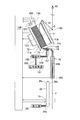
- FIG. 2 is a schematic configuration diagram of the accumulator 61.
- the accumulator 61 includes a rotary storage drum 71, a rotary storage drum motor 72, a yarn guide member 73, a blow-down nozzle 74, a yarn path forming member 75, and the like.
- the rotary storage drum 71 is a drum that can rotate around the axis C, and the yarn Y is stored by winding the yarn Y around the rotary storage drum 71 as will be described later. Further, the rotary storage drum 71 has tapered portions 71a and 71b whose diameters become smaller toward the opposite end portions, and between the tapered portion 71a and the tapered portion 71b. This portion is a straight portion 71c having a substantially constant diameter.
- a rubber annular member 81 (for example, a rubber band or an O-ring) is provided at the upper right end portion (the yarn unwinding side end portion) in FIG. 2 of the rotary storage drum 71, strictly speaking, the upper right end portion of the straight portion 71c. Resistance imparting means) is wound.
- the annular member 81 rotates integrally with the rotary storage drum 71.
- the upper right end portion of the rotary storage drum 71 is the tapered portion 71b, so that the annular member 81 is prevented from falling off from the rotary storage drum 71 to the upper right.
- the rotary storage drum motor 72 is a motor capable of position control, such as a DC brushless motor, a stepping motor, or a servo motor, and rotates the rotary storage drum 71 in both directions.
- a rotary encoder 153 is attached to the rotary storage drum motor 72, and the rotary encoder 153 transmits an angle signal according to the rotation angle of the rotary storage drum motor 72 to the control unit 109.
- the yarn guide member 73 is a pipe (tubular member) extending linearly, and is arranged so that the upper left end portion in FIG. 2 faces the taper portion 71a. As a result, the yarn Y that has traveled from the yarn supplying portion 5 side to the yarn guide member 73 is guided to the taper portion 71 a by the yarn guide member 73. Thus, in this embodiment, since the yarn Y is guided to the taper portion 71a by the yarn guide member 73 as described above, the position where the yarn Y of the rotary storage drum 71 is wound can be easily adjusted.
- the blow-down nozzle 74 (yarn end catching means) is disposed on the right side of the yarn guide member 73 in the drawing, and a yarn channel 146 connected to the internal space of the yarn guide member 73 and an opening in the yarn channel 146. And a blow-down channel 147 formed to be inclined with respect to the yarn channel 146.
- a pressure air source 151 is connected to the downflow passage 147 via a connection pipe 149 and a connection pipe 150.
- An electromagnetic valve 152 electrically connected to the control unit 109 is connected between the connection pipe 149 and the connection pipe 150. Is provided.
- the yarn path forming member 75 forms the yarn path 128 and is disposed between the suction port 26 b of the upper thread guide pipe 26 and the blow-down nozzle 74.
- the yarn path 128 extends almost directly from the lower end located immediately above the suction port 26b of the upper yarn guide pipe 26, and at its upper end, bends to the upper left in FIG. Is opposed to the lower right end portion of the yarn flow path 146 of the blow-down nozzle 74.
- the control unit 109 opens the electromagnetic valve 152, and the pressure air of the pressure air source 151 is connected to the connection pipe 150 and the connection pipe 149.
- the upper thread guide pipe 26 is connected to the internal space of the yarn guide member 73, the yarn flow path 146, and the yarn path 128 from the rotary storage drum 71 side.
- An air flow toward the side is formed. The air flow allows the yarn end of the yarn Y wound around the rotary storage drum 71 to be sucked and captured and pulled out to the yarn joining portion 8 side.
- the yarn guide member 73 is a pipe having an internal space that opens only at both ends thereof, when an air flow is generated in the internal space of the yarn guide member 73 by the blow-down nozzle 74, the inside of the yarn guide member 73 In the space, the air pressure is greatly reduced by sucking the internal air. Thereby, the yarn end of the yarn Y can be sucked strongly, and the yarn end of the yarn Y can be reliably captured.
- a pull-out sensor 154 capable of detecting that the yarn end of the yarn Y wound around the accumulator 61 is actually pulled out to the yarn joining portion 8 side is provided at the lower end of the yarn path forming member 75 described above. Yes.
- the pull-out sensor 154 is electrically connected to the control unit 109 and transmits a pull-out detection signal to the control unit 109 when detecting that the yarn end of the yarn Y has been pulled out to the yarn joining unit 8 side. It has become.
- the accumulator 61 is provided with a storage upper limit sensor 155, a storage lower limit sensor 156, and a storage lower limit sensor 157 for detecting the storage amount of the yarn Y.
- the storage upper limit sensor 155, the storage lower limit sensor 156, and the storage lower limit sensor 157 are the yarn Y wound around the rotary storage drum 71 when the storage amount of the yarn Y in the accumulator 61 is 300 m, 200 m, and 40 m, respectively. It is positioned at a position facing the upper end of the bundle.
- 300 m is a length that is equal to or longer than the length of the spun yarn Y wound by the winding unit 5 while repeating the yarn joining described later, for example, three times (at least once). Even when the winding of the spun yarn Y in the winding unit 5 is continued during the yarn splicing, the accumulator 7 is less likely to cause the yarn deficiency of the spun yarn Y.
- the storage upper limit sensor 155, the storage lower limit sensor 156, and the storage lower limit sensor 157 detect the presence of the yarn Y at the opposing position, respectively, to the control unit 109, respectively, A storage amount lower limit signal and a storage amount lower limit signal are transmitted.
- the upper right end of the yarn Y facing the storage upper limit sensor 155 when the 300 m yarn Y is wound around the rotary storage drum 71 is not the upper right end portion of the rotary storage drum 71, for example, the abbreviation of the rotary storage drum 71. It is located at a predetermined midway position of the rotary storage drum 71 such as the central portion.
- the control unit 109 shown in FIG. 3 includes a CPU (Central Processing Unit) which is an arithmetic processing unit, a ROM (Read Only Memory) in which a control program executed by the CPU and data used for the control program are stored.
- the RAM Random Access Memory
- the control program stored in the ROM is read into the CPU and executed on the CPU, whereby the control program executes hardware such as the CPU, the take-up drum motor control unit 160, the rotary storage drum motor control unit 161.
- the drawn yarn length calculation unit 163 and the upper pipe control unit 164 function.
- the winding drum motor control unit 160 controls the rotational speed of the winding drum motor 116.
- the winding unit 6 causes the yarn to rotate.
- the winding speed Va for winding Y is reduced.
- the winding drum motor control unit 160 stops receiving the storage amount lower limit signal from the storage lower limit sensor 156, the winding drum motor control unit 160 gently increases the winding speed Va so that the yarn layer of the package 30 is not disturbed. Decelerate. Further, when receiving the storage amount lower limit signal from the storage lower limit sensor 157 is interrupted, the winding drum motor control unit 160 quickly decelerates the winding speed Va and stops winding by the winding unit 6.
- the winding drum motor control unit 160 decelerates the winding speed Va when the amount of yarn Y stored in the accumulator 61 decreases, and further, when the amount of yarn Y stored in the accumulator 61 becomes extremely small, the winding unit 6 performs winding. Therefore, the yarn deficiency of the yarn Y in the accumulator 61 is prevented in advance.
- the rotary storage drum motor controller 161 controls the rotation direction of the rotary storage drum motor 72.
- the rotary storage drum motor 71 rotates so that the rotary storage drum 71 rotates in one direction.
- the storage drum motor 72 is controlled so that when the yarn end of the yarn Y on the rotary storage drum 71 is pulled out to the yarn joining portion 8 side, it rotates in the direction opposite to that when winding the yarn around the rotary storage drum 71.
- the rotary storage drum motor 72 is controlled.
- the rotary storage drum motor controller 161 (rotational speed control means) also controls the rotational speed of the rotary storage drum motor 72, as will be described later.
- the drawn yarn length calculation unit 163 is drawn from the accumulator 61 to the yarn joining unit 8 side based on the rotation angle of the rotary storage drum motor 72 detected by the rotary encoder 153 from the time when the drawing sensor 154 detects the yarn Y.
- the drawn yarn length as the yarn length of the obtained yarn Y is calculated.
- the upper pipe control unit 164 compares the yarn defect length acquired from the yarn defect detection signal with the drawn yarn length calculated by the drawn yarn length calculation unit 163, and when the drawn yarn length reaches the yarn defect length, The upper thread guide pipe 26 is turned in a clamped state, and the thread Y on the winding unit 6 side is guided to the splicer device 14 and set.
- the operator of the automatic winder (winding unit 2) unwinds the yarn Y from the yarn feeding bobbin 21, and uses the yarn Y as a yarn unwinding assisting device 12, a yarn feeler 37, a first tensor 41, a yarn clearer 15, and an accumulator. 61, the second tensor 42, and the waxing device 17 are fixed to the winding bobbin 22.
- the yarn path of the yarn Y in the accumulator 61 is as shown in FIG. That is, the operator passes the yarn Y through the pull-out sensor 154, the yarn path 128 of the yarn path forming member 75, the yarn channel 146 of the blow-down nozzle 74, and the internal channel of the yarn guide member 73 in this order.
- the operator pulls the yarn Y from the opening of the yarn guide member 73 facing the rotary storage drum 71 and winds the yarn Y around the rotary storage drum 71, for example, about 5 to 20 times. Is set on the yarn guide 82 disposed on the upper right side of the rotary storage drum 71, and then set on the second tensor 42. Note that the yarn Y in FIG. 2 is drawn thick for convenience of explanation, and the winding interval is large, but actually, the rotary storage drum 71 is always about 600 windings with a small winding interval. A bundle of wound yarns Y is stored.
- the yarn Y wound around the rotary storage drum 71 is unwound in order from the upper right end by the winding unit 6 and wound around the package 30 while being traversed by the winding drum 24.
- the yarn Y on the yarn supplying section 5 side is guided to the taper portion 71a of the rotary storage drum 71 by the yarn guide member 73 as shown in FIG.
- the guided yarn Y is wound around the tapered portion 71a.
- the yarn Y wound around the taper portion 71a sequentially moves to the upper right along the surface of the taper portion 71a substantially parallel to the axis C.
- the yarn Y is stored in the rotary storage drum 71.
- the yarn Y guided to the taper portion 71a is wound around the taper portion 71a by the rotation of the rotary storage drum 71 and slides to the upper right along the surface of the taper portion 71a.
- the yarn guide member 73 only needs to be able to guide the yarn Y to one point of the tapered portion 71a, and can be disposed relatively easily regardless of the position and orientation of the rotary storage drum 71. Therefore, the rotary storage drum 71 can be arranged relatively freely according to the empty space of the winding unit 2 and the like.
- the mechanism has a portion that rotates around the storage drum in order to allow the yarn Y to be wound around the storage drum, but the path of the yarn Y formed in this portion inevitably has a large number of bendings. It becomes a thing. As a result, the number of bends of the yarn Y that passes through such a path increases, which causes a reduction in the quality of the yarn Y.
- the path for guiding to the rotary storage drum 71 can be a path with a small number of bendings, such as a path composed of the thread path 128, the thread flow path 146 of the blow-down nozzle 74 and the internal space of the thread guide member 73. , Quality deterioration of the yarn Y can be prevented.
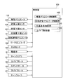
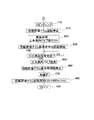
- the control unit 109 is as shown in FIG.
- the presence or absence of a yarn breakage signal is confirmed (S320)
- the presence or absence of a yarn defect detection signal is confirmed (S330)
- the presence or absence of an empty bobbin signal is confirmed (S340)
- the storage amount upper limit signal is received. Is confirmed (S350).
- FIG. 6 and 7 After executing the control flow shown in FIGS. 6 and 7 (S325, S335, S345), the control flow returns to the control flow of FIG.
- the storage upper limit sensor 155 transmits a storage amount upper limit signal to the control unit 109.
- the control unit 109 rotational storage drum motor control unit 161 receives the storage amount upper limit signal from the storage upper limit sensor 155 as shown in FIG. 5 (S350: YES), it changes the rotational speed of the rotary storage drum motor 72.
- the winding speed Vb is changed from, for example, 1500 m / min to 1200 m / min (S360).
- the winding speed Va and the winding speed Vb coincide with each other, and the storage amount of the accumulator 61 becomes constant.
- the rotary storage drum 71 has a lower left end side (pipe winding) than the portion facing the storage upper limit sensor 155.
- the yarn Y is wound only on the portion on the attachment side), and the yarn Y is not wound on the portion on the upper right end side (the yarn unwinding side).
- the fluff of the yarn Y is laid down.
- control unit 109 switches the electromagnetic valve 152 to the open state, whereby the air flow from the rotary storage drum 71 side to the upper yarn guide pipe 26 side in the internal space of the yarn guide member 73, the yarn path 128, and the like. Is formed (S420).
- control unit 109 switches the suction port 26b of the upper thread guide pipe 26 from the closed state to the open state, thereby moving the upper thread guide pipe 26 from the suction port 26b side to the negative pressure source 120 side.
- An air flow is formed (S420).
- the rotary storage drum motor control unit 161 controls the rotary storage drum motor 72 so as to rotate at a low speed in a direction opposite to that when the rotary storage drum 71 winds the yarn Y (S430). It will be in the reception waiting state of an extraction
- the yarn end of the yarn Y existing on the rotary storage drum 71 is sucked into the opening of the yarn guide member 73 and pulled out to the suction port 26b of the upper yarn guide pipe 26 via the yarn path 128 and the like.
- the rotary storage drum motor 72 is a motor whose position can be controlled, the portion of the rotary storage drum 71 where the yarn end of the yarn Y is located is accurate to the position facing the opening of the yarn guide member 73. The yarn end of the yarn Y can be reliably sucked from the opening of the yarn guide member 73.
- the moving direction of the yarn Y guided from the yarn guide member 73 to the rotary storage drum 71 is the rotational storage drum 71.
- the axial direction (direction parallel to the axis C) is a direction from the upper right end side which is the yarn unwinding side end portion toward the lower left end side which is the tapered portion 71a side.
- the yarn Y guided by the tapered portion 71a does not move to the upper right end side of the rotary storage drum 71 due to inertia when the yarn Y moves from the yarn guide member 73 to the rotary storage drum 71.
- the yarn end surely comes in the vicinity of the tapered portion 71a of the rotary storage drum 71, strictly speaking, on the lower left end portion of the straight portion 71c. Therefore, the yarn Y can be reliably sucked from the opening of the yarn guide member 73.
- the yarn guide member 73 is provided at the upper left end thereof so that both the yarn Y guide to the taper portion 71a and the suction of the yarn end of the yarn Y on the lower left end portion of the straight portion 71c can be performed. An opening is arranged to span these two parts.
- the withdrawal sensor 154 transmits a withdrawal detection signal to the control unit 109.
- the control unit 109 switches the suction port 26b from the open state to the closed state while continuing the low speed rotation of the rotary storage drum 71 and uses the clamp unit 26c.
- the yarn Y is clamped, and the upper yarn guide pipe 26 is turned from the upper side to the lower side around the shaft 26a, thereby guiding the yarn Y drawn from the accumulator 61 to the splicer device 14 of the yarn joining portion 8 (S450). ).
- the control unit 109 synchronizes the turning of the upper thread guide pipe 26 with the rotation of the rotary storage drum 71 so that the rotation is not performed.
- the control unit 109 stops the rotation of the rotary storage drum 71 (S460).
- the lower thread guide pipe 25 sucks and captures the thread end of the thread Y existing around the yarn feeler 37, and guides the thread Y to the splicer device 14. Then, when the yarn Y on the accumulator 61 side and the yarn Y on the yarn feeding unit 5 side are set in the splicer device 14, the control unit 109 causes the splicer device 14 to execute a yarn splicing operation (S470).
- control unit 109 starts to rotate in one direction of the rotary storage drum 71 as shown in FIG. 2 (S480), and returns to the normal winding state (S490).
- the rotation speed of the rotary storage drum 71 at this time is set so that the winding speed Vb is 1500 m / min (S480).
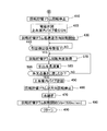
- the control unit 109 When a yarn defect is detected and the control unit 109 receives a yarn defect detection signal and a yarn cutting signal from the yarn clearer 15, the control unit 109 operates in the order of S410 to S440 as in the case of the yarn breakage. Then, when a withdrawal detection signal is received from the withdrawal sensor 154 (S440: YES), the withdrawal yarn length calculation unit 163 detects the rotary storage drum 71 detected by the rotary encoder 153 from the time when the withdrawal sensor 154 detects the yarn Y. Is obtained (S570), and the drawn yarn length is calculated based on the rotation angle (S580).
- the upper pipe control unit 64 compares the length of the yarn defect acquired from the yarn defect detection signal with the drawn yarn length calculated by the drawn yarn length calculating unit 63 (S590). Then, the upper pipe control unit 164 waits until the drawn yarn length reaches the yarn defect length (S590: NO), and when it reaches the yarn defect length (S590: YES), the above S450 ⁇ By performing the operation in the order of S480, the yarn splicing and returning to the normal winding state are performed.
- the control unit 109 receives an empty bobbin signal from the yarn feeler 37 (S340: YES)
- the current yarn supplying bobbin 21 is discharged and a new yarn supplying bobbin 21 is supplied.
- the yarn is loaded into the holding unit 60, the yarn Y of the yarn supplying bobbin 21 is guided, and the yarn can be caught and sucked into the lower yarn guide pipe 25 (S710).
- the yarn splicing and return to the normal winding state are performed by the operations of S410 to S440.
- the winding unit 2 by operating as described above, when the yarn joining is performed by the yarn joining section 6, the spun yarn Y stored in the yarn storage drum 27 is unwound, so that at least While the yarn joining operation is performed once, the winding unit 5 can continue winding the spun yarn Y around the package P. That is, the yarn joining portion 6 can perform yarn joining without interrupting the winding of the spun yarn Y onto the package P in the winding portion 5.
- the yarn Y can be pulled out to the yarn joining portion 8 side by rotating the rotary storage drum 271 in the opposite direction to the winding of the yarn Y, the yarn Y can be reliably pulled out to the yarn joining portion 8. it can.
- the yarn storage unit 9 is disposed between the yarn supplying bobbin 21 and the winding unit 6 to interrupt the transmission of the tension of the yarn Y. It is possible to prevent the tension variation due to the traverse variation of the winding unit 6 from being transmitted to the heel tension portion. Furthermore, by attaching the unwinding assisting device 12 to the yarn feeding bobbin 21, the yarn unwinding from the yarn feeding bobbin 21 can be performed stably, so that the yarn breakage is prevented and the yarn feeding bobbin 21 The unwinding speed can be increased. Therefore, the unwinding efficiency from the yarn feeding bobbin 21 can be improved.
- the height of the yarn path forming member 75 (yarn path 128) is shorter than that of the above-described embodiment.
- the rotary storage drum 71, the rotary storage drum motor 72, the yarn guide member 73, and the blow-down nozzle 74 are positioned below the above embodiment, and the yarn path forming member 75 than the above embodiment. From the left to the left in the figure. Further, a yarn path forming member 76 is attached to the lower right end portion of the blow-down nozzle 74, and the yarn flow path 146 of the blow-down nozzle 74 is passed through a thread path 129 formed inside the yarn path forming member 76. And connected to the yarn path 128.
- the winding unit 2 is set to the same height as the winding unit without the accumulator 61. It becomes possible to do.
- the position of the rotary storage drum 71 or the like is greatly different from that in the above-described embodiment, but the height of the yarn path forming member 75 (yarn path 128) is changed and the blow-down nozzle is changed.
- the thread path forming member 76 is attached to the lower right end portion of 74, and the thread channel 146 and the thread path 128 are simply connected via the thread path 129. Can be guided. Also from this, it can be seen that the rotary storage drum 71 can be arranged relatively freely according to the empty space of the winding unit 2 and the like.
- the yarn guide member 73 is a tubular member such as a pipe, and the blow-down nozzle 74 is provided in the inner space of the yarn guide member 73 from the rotary storage drum 71 side to the upper yarn guide pipe 26 side.
- the present invention is not limited to this.
- a rotary storage drum such as a mechanism for sucking the yarn end of the yarn Y on the rotary storage drum and bringing the sucked yarn Y to the suction port 26b of the upper yarn guide pipe 26, etc.
- Another mechanism capable of capturing the yarn end of the yarn Y stored in 71 may be provided.
- the yarn guide member 73 is not limited to a tubular member as long as it can guide the yarn Y to the tapered portion 71a.
- the rubber annular member 81 is wound around the upper right end portion of the rotary storage drum 71 as a resistance imparting unit.
- the annular member 81 is made of, for example, a synthetic resin material other than rubber. It may be made of a material.
- the resistance applying means is not limited to an annular member wound around the rotary storage drum 71 as long as the yarn Y is sandwiched between the surface of the rotary storage drum 71 and the outside of the rotary storage drum 71. It may be arranged in.
- the resistance applying means is preferably one that rotates integrally with the rotary storage drum 71.
- it may be fixed to a member outside the rotary storage drum 71 so as not to rotate integrally with the rotary storage drum 71.
- a metal ring attached to the rotary storage drum 71 with a predetermined clearance may be employed.
- the storage upper limit sensor 155 is opposed to the middle portion of the rotary storage drum 71, and the yarn Y is wound only on the portion on the lower left side from this portion.
- the storage upper limit sensor 155 may be disposed so as to face the upper right end portion of the rotary storage drum 71, and the yarn Y may be wound around almost the entire area of the rotary storage drum 71. In this case, the effect that the fluff of the yarn Y is laid as the yarn Y travels on the surface of the rotary storage drum 71 is reduced, but the yarn Y is stored in the rotary storage drum 71. The amount of yarn Y that can be increased.
- both end portions of the rotary storage drum 71 are tapered portions 71a and 71b whose diameters are smaller toward the opposite end portion, respectively.
- the diameter may be substantially constant.
- a part of the rotary storage drum motor 72 protrudes from the rotary storage drum 71, but the rotary storage drum 72 may be completely stored inside the rotary storage drum 71. Good.
- the rotary storage drum 71 can be arranged more freely because the rotary storage drum motor 72 does not protrude from the rotary storage drum 71.
- the yarn Y on the downstream side is wound around the rotary storage drum 71 when the yarn breaks, when the yarn defect is detected, or when the bobbin is changed.
- the occurrence is detected in advance, and the drive of the rotary storage drum 71 is stopped before all the downstream yarn Y is wound around the rotary storage drum 71.
- the cutter provided in the yarn clearer 15 cuts the yarn Y and at the same time stops driving the rotary storage drum 71.
- a sensor for detecting the remaining yarn amount of the yarn feeding bobbin 21 is attached to the yarn unwinding assisting device 12 to monitor the remaining yarn amount of the yarn feeding bobbin 21. Further, it is possible to implement a mode in which the occurrence of the empty state of the yarn supplying bobbin 21 is detected in advance and the driving of the rotary storage drum 71 is stopped before all the downstream spun yarn Y is wound around the rotary storage drum 71.
- the yarn end of the yarn Y is upstream of the blow-down nozzle 74 of the accumulator 61 or the yarn path forming member 75. It can be stopped in a state where it hangs down to the side.
- the upper yarn guide pipe 26 can catch the yarn end hanging down below the accumulator 61. Therefore, it is possible to reduce the yarn Y drawing process by the yarn end drawing mechanism, and the splicing operation can be performed. Increases efficiency.
- the withdrawal sensor 154 since the withdrawal sensor 154 is provided, the yarn end of the yarn Y stored in the accumulator 61 is stopped at a position where it can be received by the upper yarn guide pipe 26, that is, the yarn end is in the accumulator 61. It is possible to detect a state of being stopped reliably in a state of hanging down to the upstream side. Accordingly, it is possible to reduce the time required to draw the yarn end of the yarn Y from the yarn accumulating portion to the yarn joining portion side.
- the drawing mechanism of the present invention can draw not only the yarn Y completely wound up in the accumulator 61 but also the yarn Y in a state stopped below the accumulator 61 to the yarn joining portion 8 side.
- the rotation speed shown in the present embodiment is an example, and the rotation speed can be implemented in other rotation speeds and other speed units.
- Winding unit 5 Yarn supply unit 6 Winding unit 9 Yarn storage unit 21 Yarn supply bobbin 30
Landscapes
- Engineering & Computer Science (AREA)
- Textile Engineering (AREA)
- Forwarding And Storing Of Filamentary Material (AREA)
- Spinning Or Twisting Of Yarns (AREA)
- Unwinding Of Filamentary Materials (AREA)
- Winding Filamentary Materials (AREA)
Abstract
Description
この状態で、図4に示すように、巻取ユニット2の電源を投入すると(S300)、制御部109(回転貯留ドラムモータ制御部161)は、巻取部6による糸Yの巻取速度Vaが、例えば1200m/minとなるように巻取ドラム24の回転を開始させるとともに、回転貯留ドラム71における糸Yの巻付速度Vbが、例えば、1500m/minとなるように回転貯留ドラムモータ72の回転を開始させる(S310)。
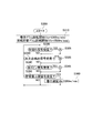
次に糸切れが発生した場合の図5の制御フローに示す動作について説明する。糸切れが発生して、制御部109が、ヤーンクリアラ15から糸切れ信号を受信すると(S320:YES)、制御部109は、まず、回転貯留ドラム71の回転を停止させる(S410)。
次に、糸欠点が検出された場合の、図6の制御フローに示す動作について説明する。ただし、このときの動作の一部は糸切れ時と同様であるので、以下では、糸切れ時と同様の動作についてはその詳細な説明を省略する。
次に、給糸ボビン21が空になった場合の、図7の制御フローに示す動作について説明する。ただし、この場合の動作の一部は糸切れ時と同様であるので、以下では、糸切れ時と同様の動作についてはその詳細な説明を省略する。
5 給糸部
6 巻取部
9 糸貯留部
21 給糸ボビン
30 パッケージ
71 回転貯留ドラム
71a テーパ部
72 回転貯留ドラムモータ
73 糸案内部材
74 糸吸引機構
81 環状部材
Claims (13)
- 給糸ボビンから紡績糸を解舒する給糸部と、
この紡績糸をパッケージとして巻き取る糸巻取部と、
前記給糸部と前記糸巻取部との間に設けられており、紡績糸を貯留する糸貯留部と、
前記給糸部側の紡績糸の糸端と、前記糸貯留部側の紡績糸の糸端とを繋ぐ糸継作業を行う糸継部と、
を備えており、
前記糸貯留部が、
回転することにより給糸ボビンから巻き上げた紡績糸を、巻き付けて貯留する回転貯留ドラムと、
前記回転貯留ドラムを両方向に回転させるモータと、
を備えたことを特徴とする糸巻取装置。 - 前記巻取部の巻取動作と前記モータの駆動とを制御する制御部を更に備え、
前記制御部は、
給糸ボビンから紡績糸を解舒して、パッケージを巻き取る通常巻取動作時には、
前記糸巻取部による巻取り動作と、前記モータにより前記回転貯留ドラムを巻き上げ方向に回転させて糸を貯留させる貯留動作とを実行させ、
前記糸継部の糸継動作が実行される時には、
前記モータにより前記回転貯留ドラムを巻き上げ方向とは逆に回転させて紡績糸を糸継部側に引き出す引出動作と、を実行させる制御モードを有することを特徴とする請求項1に記載の糸巻取装置。 - 前記制御部は、前記制御モードにおいて、
前記糸継部の糸継動作が実行される時に、
糸巻取部による巻取り動作と、前記モータにより前記回転貯留ドラムを巻き上げ方向とは逆に回転させて紡績糸を糸継部側に引き出す引出動作と、を同時に実行させることを特徴とする請求項2に記載の糸巻取装置。 - 前記回転貯留ドラムに、前記給糸部から解舒された紡績糸を案内する案内部材を更に備えた事を特徴とする請求項1~3のいずれかに記載の糸巻取装置。
- 前記回転貯留ドラムは、前記案内部材により紡績糸が案内される箇所に、テーパ部が形成されており、前記テーパ部は、紡績糸が貯留される方向に向かうほどその径が小さくなっており、
前記案内部材は、前記テーパ部に紡績糸を案内することにより紡績糸を前記回転貯留ドラムの表面上に巻き上げた順に並べて貯留することを特徴とする請求項4に記載の糸巻取装置。 - 前記糸貯留部が、
糸継作業の際に、前記回転貯留ドラム上にある紡績糸の糸端を捕捉する糸端捕捉手段をさらに備えていることを特徴とする請求項5に記載の糸巻取装置。 - 前記案内部材が管状の部材であり、
前記糸端捕捉手段が、前記案内部材の内部空間に、前記回転貯留ドラム側から前記給糸部側に向かう空気流を発生させることを特徴とする請求項6に記載の糸巻取装置。 - 前記糸貯留部が、
貯留された紡績糸の量を検出する貯留量検出手段と、
前記モータの回転速度を制御する回転速度制御手段とをさらに備えており、
前記回転速度制御手段は、貯留量検出手段により検出された紡績糸の貯留量に応じて、前記回転貯留ドラムの所定の途中位置よりも前記テーパ部側の貯留領域にのみ、紡績糸が巻き付けられるように前記モータの回転速度を制御することを特徴とする請求項5~7のいずれかに記載の糸巻取装置。 - 前記糸貯留部が、
前記回転貯留ドラムの前記糸巻取部により紡績糸が巻き出される側の端部の表面との間で紡績糸を挟むことによって、前記紡績糸に抵抗を付与する抵抗付与手段をさらに備えていることを特徴とする請求項1~8のいずれかに記載の糸巻取装置。 - 前記抵抗付与手段が、前記回転貯留ドラムと一体的に回転することを特徴とする請求項9に記載の糸巻取装置。
- 前記抵抗付与手段が、前記回転貯留ドラムの糸解舒側端部に取り付けられたゴム製の環状部材であることを特徴とする請求項10に記載の糸巻取装置。
- 前記制御モード実行時において、
前記糸貯留部は、
前記糸継部の糸継動作が少なくとも1回実行されるまでの間、
糸巻取部による巻取り動作を継続するために必要な量の紡績糸を貯留可能に構成されている事を特徴とする請求項2~11のいずれかに記載の糸巻取装置。 - 前記給糸部には、給糸ボビンの芯管に被さる規制部材を給糸ボビンからの紡績糸の解舒と連動して下降させることにより、給糸ボビンから紡績糸の解舒を補助する糸解舒補助装置が設けられていることを特徴とする請求項1~12に記載の糸巻取装置。
Priority Applications (3)
| Application Number | Priority Date | Filing Date | Title |
|---|---|---|---|
| EP10820660.8A EP2484620B1 (en) | 2009-09-30 | 2010-09-30 | Yarn winder |
| CN201080044102.3A CN102574656B (zh) | 2009-09-30 | 2010-09-30 | 纱线卷绕装置 |
| JP2011534319A JP5287992B2 (ja) | 2009-09-30 | 2010-09-30 | 糸巻取装置 |
Applications Claiming Priority (2)
| Application Number | Priority Date | Filing Date | Title |
|---|---|---|---|
| JP2009228888 | 2009-09-30 | ||
| JP2009-228888 | 2009-09-30 |
Publications (1)
| Publication Number | Publication Date |
|---|---|
| WO2011040545A1 true WO2011040545A1 (ja) | 2011-04-07 |
Family
ID=43826357
Family Applications (1)
| Application Number | Title | Priority Date | Filing Date |
|---|---|---|---|
| PCT/JP2010/067116 Ceased WO2011040545A1 (ja) | 2009-09-30 | 2010-09-30 | 糸巻取装置 |
Country Status (4)
| Country | Link |
|---|---|
| EP (1) | EP2484620B1 (ja) |
| JP (1) | JP5287992B2 (ja) |
| CN (1) | CN102574656B (ja) |
| WO (1) | WO2011040545A1 (ja) |
Cited By (4)
| Publication number | Priority date | Publication date | Assignee | Title |
|---|---|---|---|---|
| EP2626323A2 (en) | 2012-02-07 | 2013-08-14 | Murata Machinery, Ltd. | Yarn accumulating device and yarn winding device provided with the same |
| EP2990367A1 (en) | 2014-08-28 | 2016-03-02 | Murata Machinery, Ltd. | Yarn winding device |
| EP2998255A1 (en) | 2014-09-10 | 2016-03-23 | Murata Machinery, Ltd. | Yarn storage device and yarn winding device equipped with yarn storage device |
| CN114555500A (zh) * | 2019-11-15 | 2022-05-27 | 哈亚布萨有限公司 | 用于连结纺织纱线的装置和对应的连结方法 |
Families Citing this family (8)
| Publication number | Priority date | Publication date | Assignee | Title |
|---|---|---|---|---|
| JP5471923B2 (ja) * | 2010-07-15 | 2014-04-16 | 村田機械株式会社 | 糸巻取装置 |
| JP2016016969A (ja) * | 2014-07-10 | 2016-02-01 | 村田機械株式会社 | 糸貯留装置、糸巻取ユニット及び糸巻取機 |
| JP2016050059A (ja) * | 2014-08-29 | 2016-04-11 | 村田機械株式会社 | 糸巻取装置、糸継方法及び糸継ユニット |
| JP2016137959A (ja) * | 2015-01-27 | 2016-08-04 | 村田機械株式会社 | 糸巻取機 |
| JP2020143397A (ja) * | 2019-03-06 | 2020-09-10 | 村田機械株式会社 | 屑糸発生量出力装置及び繊維機械 |
| JP2023005530A (ja) * | 2021-06-29 | 2023-01-18 | 村田機械株式会社 | 糸巻取機 |
| CN114194941B (zh) * | 2021-12-10 | 2023-12-01 | 浙江云泰纺织有限公司 | 一种自动络纱机纱线卷绕机构 |
| JP2023142136A (ja) * | 2022-03-24 | 2023-10-05 | 村田機械株式会社 | 紡績機 |
Citations (4)
| Publication number | Priority date | Publication date | Assignee | Title |
|---|---|---|---|---|
| US3314621A (en) | 1963-08-14 | 1967-04-18 | Elitex Zavody Textilniho | Method of and device for winding yarn without interrupting the winding process during removal of yarn breakage |
| JPH0542262U (ja) * | 1991-11-06 | 1993-06-08 | 村田機械株式会社 | 自動ワインダの巻取ユニツト |
| JP2004156186A (ja) | 2002-11-08 | 2004-06-03 | Murata Mach Ltd | 特殊な絣糸の製造方法とその巻糸パッケージ |
| JP2004277947A (ja) * | 2003-03-17 | 2004-10-07 | Murata Mach Ltd | 糸継ぎ装置を備えた紡績機 |
Family Cites Families (10)
| Publication number | Priority date | Publication date | Assignee | Title |
|---|---|---|---|---|
| DE2553892C3 (de) * | 1975-11-29 | 1979-10-04 | Skf Kugellagerfabriken Gmbh, 8720 Schweinfurt | Abzugsvorrichtung für eine Offenendspinnmaschine |
| DE2558419A1 (de) * | 1975-12-23 | 1977-07-07 | Schubert & Salzer Maschinen | Offen-end-spinnvorrichtung |
| US4106713A (en) * | 1976-05-12 | 1978-08-15 | Aktiebolaget Iro | Thread feeder for textile machines |
| CS237357B1 (en) * | 1983-06-24 | 1985-07-16 | Genadij Terechin | Device for drawing off and winding of yarn |
| CH680863A5 (ja) * | 1989-03-17 | 1992-11-30 | Sulzer Ag | |
| SE9703369D0 (sv) * | 1997-09-16 | 1997-09-16 | Iro Ab | Verfahren zum zwischenspeichern von faden und liefergerät |
| JP4048902B2 (ja) * | 2002-10-07 | 2008-02-20 | 村田機械株式会社 | 紡績機の糸弛み取り装置 |
| ITMI20042190A1 (it) * | 2003-11-27 | 2005-02-16 | Murata Machinery Ltd | Dispositivo avvolgitore di fili e rocca per avvolgere fili |
| ITUD20050142A1 (it) * | 2005-09-14 | 2007-03-15 | Sergio Zamattio | Metodo e dispositivo di roccatura di un filato e corpo avvolto cosi' realizzato |
| JP5007826B2 (ja) * | 2008-03-31 | 2012-08-22 | 村田機械株式会社 | 糸巻取装置及びこの糸巻取装置を備える自動ワインダ |
-
2010
- 2010-09-30 EP EP10820660.8A patent/EP2484620B1/en active Active
- 2010-09-30 WO PCT/JP2010/067116 patent/WO2011040545A1/ja not_active Ceased
- 2010-09-30 JP JP2011534319A patent/JP5287992B2/ja not_active Expired - Fee Related
- 2010-09-30 CN CN201080044102.3A patent/CN102574656B/zh active Active
Patent Citations (4)
| Publication number | Priority date | Publication date | Assignee | Title |
|---|---|---|---|---|
| US3314621A (en) | 1963-08-14 | 1967-04-18 | Elitex Zavody Textilniho | Method of and device for winding yarn without interrupting the winding process during removal of yarn breakage |
| JPH0542262U (ja) * | 1991-11-06 | 1993-06-08 | 村田機械株式会社 | 自動ワインダの巻取ユニツト |
| JP2004156186A (ja) | 2002-11-08 | 2004-06-03 | Murata Mach Ltd | 特殊な絣糸の製造方法とその巻糸パッケージ |
| JP2004277947A (ja) * | 2003-03-17 | 2004-10-07 | Murata Mach Ltd | 糸継ぎ装置を備えた紡績機 |
Non-Patent Citations (1)
| Title |
|---|
| See also references of EP2484620A4 * |
Cited By (7)
| Publication number | Priority date | Publication date | Assignee | Title |
|---|---|---|---|---|
| EP2626323A2 (en) | 2012-02-07 | 2013-08-14 | Murata Machinery, Ltd. | Yarn accumulating device and yarn winding device provided with the same |
| JP2013159467A (ja) * | 2012-02-07 | 2013-08-19 | Murata Machinery Ltd | 糸貯留装置、及び、この糸貯留装置を備えた糸巻取装置 |
| EP2626323A3 (en) * | 2012-02-07 | 2014-04-09 | Murata Machinery, Ltd. | Yarn accumulating device and yarn winding device provided with the same |
| EP2626323B1 (en) | 2012-02-07 | 2015-06-03 | Murata Machinery, Ltd. | Yarn winding device provided with a yarn accumulating device |
| EP2990367A1 (en) | 2014-08-28 | 2016-03-02 | Murata Machinery, Ltd. | Yarn winding device |
| EP2998255A1 (en) | 2014-09-10 | 2016-03-23 | Murata Machinery, Ltd. | Yarn storage device and yarn winding device equipped with yarn storage device |
| CN114555500A (zh) * | 2019-11-15 | 2022-05-27 | 哈亚布萨有限公司 | 用于连结纺织纱线的装置和对应的连结方法 |
Also Published As
| Publication number | Publication date |
|---|---|
| CN102574656A (zh) | 2012-07-11 |
| JP5287992B2 (ja) | 2013-09-11 |
| EP2484620A4 (en) | 2013-06-26 |
| JPWO2011040545A1 (ja) | 2013-02-28 |
| EP2484620B1 (en) | 2015-11-04 |
| EP2484620A1 (en) | 2012-08-08 |
| CN102574656B (zh) | 2013-08-28 |
Similar Documents
| Publication | Publication Date | Title |
|---|---|---|
| JP5287992B2 (ja) | 糸巻取装置 | |
| JP5007826B2 (ja) | 糸巻取装置及びこの糸巻取装置を備える自動ワインダ | |
| CN101994176B (zh) | 纺纱机械 | |
| EP2157039B1 (en) | Textile machine | |
| CN103443005B (zh) | 纱线卷绕装置及纱线卷绕方法 | |
| JP2013067475A (ja) | 糸巻取機及び糸巻取ユニット | |
| JP2013241231A (ja) | 糸巻取装置及び糸巻取方法 | |
| CN102574655B (zh) | 纱线卷绕装置 | |
| JP5375967B2 (ja) | 糸巻取装置 | |
| JP2013067891A (ja) | 紡績ユニット及び紡績機 | |
| JP2016194188A (ja) | 少なくとも1つのリング精紡機と少なくとも1つの巻取り機とから成る複合システムを運転する方法並びに複合システム | |
| JP5365698B2 (ja) | 糸巻取装置 | |
| JP2016016958A (ja) | 糸巻取機及び糸巻取方法 | |
| WO2015029292A1 (ja) | 糸巻取装置 | |
| CN112110281B (zh) | 纱线卷绕装置及包头纱形成方法 | |
| JP2007290839A (ja) | 巻き終わり糸の制御装置 | |
| CN114575006A (zh) | 纺纱机械 | |
| JP2023142136A (ja) | 紡績機 | |
| WO2012120963A1 (ja) | 糸貯留引出装置及び糸巻取装置 | |
| JP2024007744A (ja) | 紡績機、パッケージの形成方法及びパッケージ | |
| JP2022085990A (ja) | 紡績機及び紡績方法 | |
| JP2023145987A (ja) | 糸巻取機及び糸巻取方法 | |
| JPS5938327B2 (ja) | 紡機の自動糸継方法 |
Legal Events
| Date | Code | Title | Description |
|---|---|---|---|
| WWE | Wipo information: entry into national phase |
Ref document number: 201080044102.3 Country of ref document: CN |
|
| 121 | Ep: the epo has been informed by wipo that ep was designated in this application |
Ref document number: 10820660 Country of ref document: EP Kind code of ref document: A1 |
|
| WWE | Wipo information: entry into national phase |
Ref document number: 2011534319 Country of ref document: JP |
|
| NENP | Non-entry into the national phase |
Ref country code: DE |
|
| WWE | Wipo information: entry into national phase |
Ref document number: 2010820660 Country of ref document: EP |
|
| WWE | Wipo information: entry into national phase |
Ref document number: 1023/KOLNP/2012 Country of ref document: IN |