WO2011042988A1 - ワークの位置決め装置及び方法並びに突合せ溶接用ワークの位置決め装置 - Google Patents
ワークの位置決め装置及び方法並びに突合せ溶接用ワークの位置決め装置 Download PDFInfo
- Publication number
- WO2011042988A1 WO2011042988A1 PCT/JP2009/067655 JP2009067655W WO2011042988A1 WO 2011042988 A1 WO2011042988 A1 WO 2011042988A1 JP 2009067655 W JP2009067655 W JP 2009067655W WO 2011042988 A1 WO2011042988 A1 WO 2011042988A1
- Authority
- WO
- WIPO (PCT)
- Prior art keywords
- workpiece
- stopper
- work
- positioning
- support member
- Prior art date
- Legal status (The legal status is an assumption and is not a legal conclusion. Google has not performed a legal analysis and makes no representation as to the accuracy of the status listed.)
- Ceased
Links
Images


Classifications
-
- B—PERFORMING OPERATIONS; TRANSPORTING
- B23—MACHINE TOOLS; METAL-WORKING NOT OTHERWISE PROVIDED FOR
- B23K—SOLDERING OR UNSOLDERING; WELDING; CLADDING OR PLATING BY SOLDERING OR WELDING; CUTTING BY APPLYING HEAT LOCALLY, e.g. FLAME CUTTING; WORKING BY LASER BEAM
- B23K37/00—Auxiliary devices or processes, not specially adapted for a procedure covered by only one of the other main groups of this subclass
- B23K37/04—Auxiliary devices or processes, not specially adapted for a procedure covered by only one of the other main groups of this subclass for holding or positioning work
- B23K37/0408—Auxiliary devices or processes, not specially adapted for a procedure covered by only one of the other main groups of this subclass for holding or positioning work for planar work
Definitions
- the present invention relates to a workpiece positioning device and method and a butt welding workpiece positioning device, and more particularly to a workpiece positioning device and method suitable for use prior to butt welding of a thin plate (work).
- a reciprocating member driven by an actuator is provided below the cradle on which the workpiece is placed.
- An adsorbing device is supported on the reciprocating member so as to be vertically movable and tiltable. Then, the lower surface of the work placed on the cradle is sucked by the suction device, and then the reciprocating member is displaced by the actuator to press the work toward the stopper.
- the pressing can be performed by sucking the lower surface of the workpiece with the suction device. .
- the edge of the workpiece that abuts against the stopper exists only in the portion that is offset to one side with respect to the overall width of the workpiece, the workpiece is offset when the suction device that attracts the workpiece is moved. In addition, there is a problem that the workpiece falls about one corner of the edge of the abutting portion.
- the present invention has been made to solve such problems.
- the object of the present invention is to provide a workpiece that can accurately position the workpiece with respect to the stopper even if the workpiece has a special shape. It is an object to provide a positioning apparatus and method, and a positioning apparatus for a butt welding work.
- a positioning device for positioning a plate-shaped workpiece, and a platform unit for fixing the workpiece, and the workpiece is conveyed toward the platform unit.
- the transport unit includes a suction portion that sucks the workpiece, a support member having the suction portion, a rotation axis that is a rotation center of the support member and is perpendicular to the plate surface of the workpiece, and a plate of the workpiece
- An actuating member that is parallel to the surface and capable of moving in a direction perpendicular to the abutting surface of the workpiece, and a control device that controls movement of the actuating member and rotation of the support member.
- the pivot shaft is a vertical plane passing through the abutting surfaces, and to provide a positioning device of a work, characterized in that located within the side edges of the abutting surfaces in plan view.
- the support member extends in parallel with the plate surface of the workpiece from the rotation shaft, and the suction portion is disposed at least at a tip portion of the support member. It is characterized by being.
- the angle at which the support member rotates about the rotation axis is limited to an angle at which the abutting surface can be brought into contact with the stopper. It is characterized by having.
- the work positioning apparatus is characterized in that, in claim 1, the actuating member has an air cylinder for pressing the work against the stopper at the abutting surface.
- the platform unit has a side stopper for coming into contact with a side surface of the workpiece other than the abutting surface, and the operating member has a side surface of the workpiece. In order to make it contact
- the said positioning device conveys the said workpiece
- a transfer unit, and the platform unit includes a cradle for placing the workpiece, and a stopper provided on the cradle and abutted against the abutting surface of the workpiece.
- the unit includes an adsorption portion that adsorbs the workpiece, a support member having the adsorption portion, a rotation axis that is a rotation center of the support member and is perpendicular to a plate surface of the workpiece, and the rotation axis.
- An actuating member that is parallel to the plate surface of the workpiece and is movable in a direction perpendicular to the butting surface of the workpiece, and the positioning method sucks the workpiece onto the suction portion.
- the actuating member is moved to a position where the pivot shaft intersects a vertical line passing through the abutting surface, the support member is pivoted around the pivot shaft, and the work is pressed against the stopper to come into contact therewith.
- a workpiece positioning method is provided.
- the platform unit further includes a side stopper for contacting a side surface of the workpiece other than the abutting surface, and presses the workpiece against the stopper. After the contact, the operating member is moved in a direction parallel to the abutting surface of the workpiece, and the side surface of the workpiece is brought into contact with the side stopper.
- the workpiece positioning method wherein the support member has at least two suction portions, and when the workpiece is sucked to the suction portion, the two suction portions have the workpiece in a plan view.
- the workpiece is adsorbed at positions opposite to each other across the center of gravity position.
- a workpiece positioning apparatus for positioning and welding a plate-like workpiece, the platform unit for fixing the workpiece, and for transporting the workpiece toward the platform unit.
- the cradle unit includes a cradle and a stopper according to claim 1, and a clamp member for pressing the workpiece against the cradle from above the cradle,
- the transport unit includes the suction portion, the support member, the rotation shaft, and the operation member according to claim 1, wherein the rotation shaft is a vertical surface passing through the abutting surface and the abutting surface in a plan view.
- a workpiece positioning device is provided which is located within a range of both side edges of the workpiece.
- the platform unit has a side stopper for contacting a side surface of the workpiece other than the abutting surface, and the operating member is configured to move the side surface of the workpiece.
- the workpiece In order to contact the side stopper, the workpiece can move in a direction parallel to the abutting surface of the workpiece.
- the workpiece positioning device wherein the cradle and the clamp member are in a direction perpendicular to the abutting surface in a state in which the cradle and the clamp member are pressed against the cradle by the clamp member. It is possible to move.
- the operation member can be operated by the control device, and the edge of the workpiece can be brought into contact with the stopper with a pressing force.
- work can be rotated with a support member and the edge of a workpiece
- work can be stuck to a stopper.
- the abutment surface of the workpiece and the stopper is flat, even if the abutment surface of the workpiece is not slightly parallel to the stopper before the abutment of the workpiece and the stopper, it can be made parallel.
- Positioning can be achieved.
- the axis for rotating the support member (that is, the point at which the pressing force acts on the support member in plan view) is parallel to the plate surface of the workpiece and viewed along the direction perpendicular to the workpiece contact surface. Sometimes it is located within the range inside the ends of the butted surfaces. That is, the rotation shaft of the support member is a vertical plane passing through the abutting surface and is located within a range of both side edges of the abutting surface in plan view. For this reason, the rotational moment centering on the corner
- the support member extends away from the rotation shaft (axis) in a plan view, and the suction portion is provided at least at the tip.
- the axis which is the point of action of the pressing force can be separated from the suction point by the suction member. Therefore, even if the workpiece has a special shape, the range of the edge of the workpiece when the axis of rotation of the support member is viewed along the direction parallel to the plate surface of the workpiece and perpendicular to the edge of the workpiece. It is easy to be located inside. Thereby, even if it is a workpiece
- the rotation of the support member around the rotation axis with respect to the operating member is limited to a predetermined angle range, when the workpiece is moved toward the stopper, Thus, even if a rotational moment is applied, the workpiece posture can be prevented from changing greatly.
- the rotation angle is limited to an angle within which the abutting surface can be brought into contact with the stopper, there is no problem in positioning the workpiece.
- the abutting surface of the workpiece is pressed against the stopper by the air cylinder. For this reason, a pressing force can be easily adjusted to an appropriate magnitude
- the workpiece positioning apparatus of the fifth aspect is moved so that the side surface other than the workpiece abutting surface abuts the side stopper in a state where the actuating member is actuated and the abutting surface of the workpiece abuts the stopper. Can be made. For this reason, it is possible to accurately position not only in a direction perpendicular to the abutting surface of the workpiece but also in a direction parallel to the abutting surface of the workpiece.
- the butting surface of the workpiece is brought into contact with the stopper with a pressing force. For this reason, the workpiece can be rotated together with the support member, and the edge of the workpiece can be brought into close contact with the stopper. For example, if the abutment surface of the workpiece and the stopper is flat, even if the abutment surface of the workpiece is not slightly parallel to the stopper before the abutment of the workpiece and the stopper, it can be made parallel. Positioning can be achieved.
- the axis for rotating the support member (that is, the point at which the pressing force acts on the support member in plan view) is parallel to the plate surface of the workpiece and viewed along the direction perpendicular to the workpiece contact surface. Sometimes it is located within the range inside the ends of the butted surfaces. That is, the rotation shaft of the support member is a vertical plane passing through the abutting surface and is located within a range of both side edges of the abutting surface in plan view. For this reason, the rotational moment centering on the corner
- the operation member is operated to move the workpiece so that the side surface other than the workpiece abutting surface abuts the side stopper in a state where the abutting surface of the workpiece abuts the stopper. Can do. For this reason, it is possible to accurately position not only in a direction perpendicular to the abutting surface of the workpiece but also in a direction parallel to the abutting surface of the workpiece.
- the support member has at least two suction portions, and the two suction members are located on the opposite sides with respect to the position of the center of gravity of the work in plan view. In this state, the work is attracted, so that when the work is moved by the support member, the occurrence of a rotational moment on the work can be reduced.
- the operating member is operated by the control device, and the butt surface of the work is brought into contact with the stopper with a pressing force. For this reason, the workpiece can be rotated together with the support member, and the edge of the workpiece can be brought into close contact with the stopper. For example, if the abutting surface of the workpiece and the stopper is flat, even if the abutting surface of the workpiece is not slightly parallel to the stopper before the workpiece and the stopper are abutted, this can be made parallel. Positioning can be achieved.
- work is reliably positioned with respect to a receiving stand by pressing a workpiece
- the axis for rotating the support member (that is, the point at which the pressing force acts on the support member in plan view) is parallel to the plate surface of the workpiece and viewed along the direction perpendicular to the workpiece contact surface. Sometimes it is located within the range inside the ends of the butting surfaces. That is, the rotation shaft of the support member is a vertical plane passing through the abutting surface, and is located within a range of both side edges of the abutting surface in a plan view. For this reason, the rotational moment centering on the corner
- the actuating member is operated so that the side face other than the butt face of the work comes into contact with the side stopper in a state where the butt face of the work comes into contact with the stopper.
- the workpiece can be moved. For this reason, it is possible to accurately position not only in a direction perpendicular to the abutting surface of the workpiece but also in a direction parallel to the abutting surface of the workpiece.
- the workpiece accurately positioned on the cradle can be firmly fixed to the cradle by the clamp member.
- the stopper is moved to the rest position, and then the workpiece is moved to the normal welding position together with the cradle, whereby the positioning of the workpiece for butt welding can be completed.
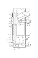
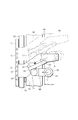
- FIG. 6 is an enlarged plan view of a support member 86 and a third arm 66 in FIG. 4.
- FIG. 6 is a side view of FIG. 5.
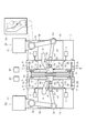
- two movable platforms 6 are movably supported on a rail 4 provided on a base 2 and extending in the horizontal direction of the drawing (hereinafter referred to as “longitudinal direction” for convenience). These moving bases 6 are moved to an arbitrary position on the rail 4 by an extendable cylinder 8 attached to the base 2 and stopped at that position.
- Each of the movable table 6 and each member placed on the movable table 6 is a table unit.
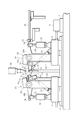
- the movable table 6 includes a receiving table 10 on which plate-like workpieces A and B are placed, a stopper device 12 for the workpieces A and B, and a clamping device 14 that clamps the workpieces A and B between the receiving table 10. Is provided.
- work A and B are each butt-welded each edge A1 and B1.
- the cradle 10 extends in the vertical direction of the drawing (hereinafter referred to as “width direction” for convenience) and is firmly attached to the movable table 6.
- the stopper device 12 is bridged between an arm-like turning member 18 rotatably supported by support members 16 fixed to both ends in the width direction of the movable table 6 and the left and right turning members 18, 18.
- a stopper support member 22 having a plurality of stoppers 20 arranged on a straight line.
- the stopper support member 22 is also supported at an appropriate position in the central portion by a rotation member (not shown) provided concentrically with the rotation member 18 so that the central portion is not deformed.
- An expansion / contraction cylinder 24 is provided between each of the left and right rotating members 18 and the moving base 6, and the expansion / contraction cylinder 24 allows the stopper 20 to be used (stopper 20 on the right side in FIG. 2) and rest position (FIG. 2). To the left stopper 20).
- the clamping device 14 is rotatably supported by support members 26 fixed to both ends in the width direction of the movable table 6, and includes a rotating member 28 having two arm portions 28 a and 28 b, and left and right rotating members 28.
- a clamp support member 30 is provided between the arm portions 28a and 28a and is positioned above the cradle 10 described above. As shown in FIGS. 2 and 3, the clamp support member 30 is provided with a plurality of pressing pads 32 arranged along the longitudinal direction of the clamp support member 30.
- a strong spring 34 is interposed between each pressing pad 32 and the clamp support member 30.
- an extendable cylinder 36 is provided between each arm portion 28 b and the movable table 6.
- the pressing pad 32 can press the workpiece A against the receiving base 10 (clamping position (the clamping device 14 on the right side in FIG. 2)).
- the pressing pad 32 can be moved so as to be retracted above the cradle 10 (unclamping position (the clamping device 14 on the left side in FIG. 2)).
- cradles 38 and 40 having the same height as the cradle 10 are arranged so as to be aligned with the cradle 10. These cradles 38 and 40 are firmly fixed to the base 2.
- the cradles 38 and 40 are shown in a flat plate shape in the drawing, it is also possible to adopt a sword-like shape formed by a plurality of narrow members extending in the longitudinal direction of FIG.
- guide members extending in the width direction are provided between the cradles 10 and 38 and between the cradles 38 and 40, respectively.
- Two side stoppers 42 and auxiliary side stoppers 43 are movably attached to each guide member. These side stoppers 42 can be moved to arbitrary positions by an actuator (not shown).
- each robot 50 has a first arm 56 attached to the main body 52 so as to rotate via a first shaft 54 extending in the vertical direction, and a tip of the first arm 56. And a second arm 60 attached so as to rotate via a second shaft 58 extending in the vertical direction. Further, a third arm 66 is attached to the tip of the second arm 60 so as to rotate via a third shaft 62 extending in the vertical direction and to move up and down via a lifting device 64.
- the third arm 66 includes a base portion 68 attached to the second arm 60 so as to be rotatable and movable up and down, a first arm portion 70 fixed to the base portion, and a first arm portion 70. It has the 2nd arm part 72 engaged so that the one arm part 70 could slide to a longitudinal direction.
- a sleeve-like base body 74 is fixed to the tip of the second arm portion 72.
- the air cylinder 76 attached to the first arm portion 70 has its operating shaft 78 engaged with the base body 74.
- the maximum sliding amount of the second arm portion 72 with respect to the first arm portion 70 is regulated by a stopper (not shown), and air pressure is applied in a direction in which the air cylinder 76 is always extended. As a result, the second arm portion 72 is maintained in a state in which it slides to the maximum with respect to the first arm portion 70 unless an external force is applied.
- a rotating shaft 80 is supported on the base body 74 through a bearing so as to be rotatable about a vertical axis.
- a key member protrudes from a part of the outer periphery of the rotating shaft 80, and the key member engages with a part of the base body 74, so that the rotating range of the rotating shaft 80 relative to the base body 74 is set at a predetermined angle. (For example, 10 degrees).
- an elastic member such as a spring that urges the rotation shaft 80 to be positioned at the neutral position of the rotation range with respect to the base body 74 is not shown between the rotation shaft 80 and the base body 74. Is provided.
- a support member 86 is attached to the lower end portion of the shaft 80 via a shaft 82 and a bracket 84.
- the support member 86 extends away from the base body 74 in plan view, and is provided with a vacuum type suction portion (hereinafter referred to as a suction member) 88 at a portion close to the base body 74 and a tip portion.
- the adsorption member 88 can also employ an electromagnetic adsorption member.
- the shaft 82 is detachably fixed at an arbitrary angle in the rotation direction with respect to the rotation shaft 80.
- the welding torch 90 is arranged at the center position of the two movable platforms 6 as is apparent from FIG. At the same position, the workpieces A and B can be moved along the butt line.
- a groove member 92 opened upward is provided below the butt line so as to extend along the butt line.
- a stock table 94 for placing the stocked workpiece A is provided.
- the stock table 94 is arranged in a range where the support member 86 operated by the robot 50 reaches the workpiece A on the stock table 94.
- a stock stand similar to the stock stand 94 is also provided corresponding to the left robot 50.
- the control device 48 controls the robot 50 as follows. First, as shown by a two-dot chain line in FIG. 1, the arms 56, 60 and 66 are operated so that the support member 86 is positioned at a position corresponding to the workpiece A on the stock table 94. Next, the base 74 is lowered together with the third arm 66 by the lifting device 64, and the work A is sucked by the suction member 88.
- the workpiece A is lifted together with the third arm 66 by the lifting device 64, loaded onto the receiving bases 38 and 40, and placed on the receiving beds 38 and 40 by the lifting device 64.
- the work piece A is placed so that the end edge A ⁇ b> 1 to be butt welded is substantially parallel to the stopper 20 in the use position.
- each arm 56, 60 and 66 is operated to bring the end A1 of the workpiece A into contact with the stopper 20, and further extended to the maximum length by the air cylinder.
- the workpiece A is pressed against the stopper 20 so that the third arm 66 is slightly reduced (for example, 10 to 20 mm). At this time, the vicinity of the edge A1 of the workpiece A is positioned on the cradle 10. As a result, as indicated by a two-dot chain line 98, the end edge of the workpiece A is brought into close contact with the stopper 20 arranged linearly in the width direction.
- the arms 56, 60 and 66 are operated, and the workpiece A is pressed against the stopper 20 so as to come into contact with the stopper 42 previously arranged at a normal position in the width direction (vertical direction in FIG. 7). (Downward in FIG. 7). As a result, as indicated by the solid line in FIG. 7, the workpiece A is in close contact with the stopper 20 in the longitudinal direction and is in contact with the side stopper 42 in the width direction, with respect to the receiving table 10 on the movable table 6. Positioned with a normal posture.
- the side auxiliary stopper 43 is positioned in advance at a position where there is a slight gap (for example, 5 mm) with respect to the workpiece A in a state where the workpiece A is in contact with the side stopper 42. This is due to the friction between the work A and the stopper 20 or the cradle 10 when the work A is moved at high speed from the position shown by the two-dot chain line 98 in FIG. The work A is rarely going to fall, and plays a role in preventing it.
- the pad 32 of the clamping device 14 is moved to the clamping position. That is, the extension cylinder 36 of the clamp device 14 is extended to lower the clamp 32, and the workpiece A is clamped between the pad 32 of the clamp 32 and the cradle 10. Thereby, the workpiece
- the telescopic cylinder 24 of the stopper device 12 is reduced, and the stopper 20 is moved together with the stopper support member 22 to the storage position.
- the movable table 6 is advanced by the extension of the telescopic cylinder 8 while the workpiece A is fixed by the clamp device 14 so that the edge A1 of the workpiece A is positioned at a predetermined position below the welding torch 90.
- the workpiece B is also positioned with respect to the cradle 10 by the left robot in FIG.
- the edge B1 of the workpiece B is positioned at a predetermined position below the welding torch 90.
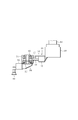
- the edge A1 of the workpiece A and the rotation center of the support member 86 that supports the workpiece A is shown.
- the workpiece A is pressed by the robot 50 so that the end surface A ⁇ b> 1 contacts the stopper 20.
- the point of action of the pressing force is the third shaft 62 that is the rotation center of the support member 86, that is, the rotation center of the third arm 66.
- the pressing force is taken as a vector, it is parallel to the plate surface of the workpiece A and along the direction perpendicular to the edge A1 as indicated by an arrow V in FIG.
- the rotation center of the support member 86 (that is, the center of the third shaft 62), which is the point of action of the pressing force, is within the range of the edge A1 of the workpiece A. Further, the adsorption point of the workpiece by the adsorption member 88 is selected.
- the workpiece A when the workpiece A is pressed by the robot 50, the workpiece A does not generate a rotational moment about the corner of one end of the end A1, so that the workpiece A falls down due to the pressing. Trouble can be solved.
- the two suction members 88 are selected so as to be positioned on opposite sides of the center of gravity of the workpiece A in plan view. Thereby, when the work A is carried in from the stock table 94, the wobbling of the work A can be minimized. Further, even if the support member 86 moves in parallel when the workpiece A is moved from the position indicated by the two-dot chain line 98 in FIG. 7 to the position indicated by the solid line A, the occurrence of a rotational moment on the workpiece A can be reduced.
- the rotation range of the support member 86 relative to the base body 74 is restricted. Accordingly, it is possible to prevent the workpiece A from fluctuating greatly when the workpiece A is carried in from the receiving platform 10 or the workpiece platform 94. Furthermore, the shaft 82 fixed to the support member 86 can be detachably fixed at an arbitrary angle in the rotation direction with respect to the rotation shaft 80. On the other hand, the longitudinal direction of the third arm 66 is substantially equal to the direction of the pressing force with respect to the workpiece A. Therefore, the angle formed by the direction of the pressing force with respect to the workpiece A and the longitudinal direction of the support member 86 can be easily changed by changing and fixing the rotation angle of the shaft 82 with respect to the rotation shaft 80.
- a support member 86 having a different size or shape is prepared in advance according to a workpiece having a different shape and is disposed near the robot 50 and positioning a workpiece having a different shape
- the support member 86 is provided.
- the positioning operation can be rapidly advanced.
- the robot 50 operates each of the arms 56, 60 and 66, and the work A on the stock table 94 is sucked by the suction member 88 and is carried onto the receiving tables 38 and 40. Therefore, a dedicated device for carrying the workpiece A onto the cradle 10, 38 or 40 is not required, and the equipment cost can be reduced.
- the robot 50 carries the workpiece A onto the cradles 38 and 40, but instead, it is configured to carry the workpiece A onto the cradles 38 and 40 separately by a dedicated loader. Is also possible.
- the direction of the pressing force with respect to the workpiece A and the longitudinal direction of the support member 86 can be easily changed by changing and fixing the angle of the rotation direction of the shaft 82 with respect to the rotation shaft 80.
- the workpiece is set so that the point of action of the pressing force is within the range of the edge to be abutted against the stopper. So that it can be adsorbed.
- the support member 86 by configuring the support member 86 to be rotatable at an arbitrary angle with respect to the third arm 66 by the actuator, it is possible to cope with workpieces having different shapes in the same manner.
- the workpiece A is configured to contact the stopper 20 to position the workpiece A.
- the mating workpiece is fixed in advance to a normal position, and the mating workpiece is fixed. It is also possible to use the edge of the in place of the stopper.
- the said embodiment was applied to the butt-welding apparatus, it cannot be overemphasized that the positioning apparatus which concerns on this invention can be applied other than a butt-welding apparatus.
Landscapes
- Physics & Mathematics (AREA)
- Optics & Photonics (AREA)
- Engineering & Computer Science (AREA)
- Mechanical Engineering (AREA)
- Jigs For Machine Tools (AREA)
- Separation, Sorting, Adjustment, Or Bending Of Sheets To Be Conveyed (AREA)
- Grinding And Polishing Of Tertiary Curved Surfaces And Surfaces With Complex Shapes (AREA)
- Feeding Of Articles By Means Other Than Belts Or Rollers (AREA)
- Automatic Assembly (AREA)
- Manipulator (AREA)
Abstract
Description
これにより、特殊な形状のワークであっても、不具合を生じることなく、位置決めを達成することができる。
図1及び図2において、基台2上に設けられ図左右方向(便宜上、以後「長手方向」と称す)に延びたレール4に2つの移動台6が移動可能に支持されている。これら移動台6は、基台2に取り付けられた伸縮シリンダ8により、レール4上の任意の位置に移動され、その位置で停止されるものである。この移動台6および移動台6に載置された各部材が台ユニットである。移動台6には、板状のワークA及びBを載置される受け台10、ワークA及びBに対するストッパ装置12、及びワークA及びBを受け台10との間に挟圧するクランプ装置14が設けられている。なお、ワークA及びBは、それぞれの端縁A1及びB1を互いに突合せ溶接されるものである。
ストッパ装置12は、移動台6の幅方向両端部に固定された支持部材16に回転自在に支持されたアーム状の回動部材18と、左右の同回動部材18,18間に橋設されると共に上面に複数のストッパ20が直線上に配置されたストッパ支持部材22を有している。ストッパ支持部材22は、中央部が変形しないように、回動部材18と同心的に設けられた図示しない回動部材により、中央部の適当箇所も支持されている。左右の各回動部材18と移動台6との間には伸縮シリンダ24が設けられており、同伸縮シリンダ24により、ストッパ20が使用位置(図2の右側のストッパ20)と休止位置(図2の左側のストッパ20)とに移動することができる。
図1において、制御装置48は以下のとおりロボット50を制御する。先ず、図1に2点鎖線で示されるように、ストック台94上のワークAに対応する位置に支持部材86が位置するように各アーム56、60及び66を作動する。次いで、昇降装置64により基体74を第3アーム66と共に下降させ、吸着部材88によりワークAを吸着する。そして昇降装置64により第3アーム66と共に上昇させ、ワークAを受け台38及び40上に搬入し、昇降装置64によりワークAを受け台38及び40上に載置する。このとき、図7に二点鎖線96で示されるように、ワークAの突合せ溶接される端縁A1が上記使用位置にあるストッパ20と概ね平行になるように載置される。次いで、図7に二点鎖線98で示されるように、各アーム56、60及び66を作動させてワークAの当該端縁A1をストッパ20に当接させ、更にエアシリンダにより最大長に伸長されている第3アーム66が若干量(例えば10~20ミリメートル)縮小するようにワークAをストッパ20に押し付ける。なお、このとき、ワークAにおける端縁A1の近傍部分は受け台10上に位置されている。これにより、二点鎖線98で示されるように、ワークAの当該端縁が幅方向に直線状に並べられたストッパ20に密に当接される。
まず、ワークAの端縁A1と、同ワークAを支持する支持部材86の回動中心との関係である。図7に従って説明すると、ワークAは、ロボット50により、その端面A1がストッパ20に当接するように押圧される。その押圧力の作用点は、支持部材86の回動中心、すなわち第3アーム66の回動中心である第3軸62である。その押圧力はベクトルとしてとらえると、図7に矢印Vで示したとおり、ワークAの板面と平行かつその端縁A1と直角方向に沿うものである。そして、当該ベクトルVに沿って見たときに、押圧力の作用点である支持部材86の回動中心(つまり第3軸62の中心)が、ワークAの端縁A1の範囲内にあるように、吸着部材88によるワークの吸着点が選定されている。
また、支持部材88とワークAの吸着点の関係において、2つの吸着部材88が平面視におけるワークAの重心を挟んで反対側に位置するように選定されている。これにより、ワークAをストック台94から搬入する際にワークAのふらつきを最小限に抑えることができる。またワークAを図7に二点鎖線98で示す位置から実線Aで示される位置移動するときに支持部材86が平行移動しても、ワークAに回転モーメントの発生することを低減できる。
さらに、支持部材86に固定された軸82は、回動軸80に対して回動方向において任意の角度でもってかつ着脱自在に固定することができる。他方、第3アーム66の長手方向は、実質的にワークAに対する押圧力の向きに等しい。したがって、軸82の回動軸80に対する回動方向の角度を変えて固定することにより、ワークAに対する押圧力の向きと支持部材86の長手方向との成す角度を容易に変えることができる。これにより、異なる形状のワークに対しても、ワークに対する押圧力に沿って見たときに、該押圧力の作用点が、ストッパに突合せられる端縁の範囲内にあるように、該ワークを吸着することができるという効果がある。特に、支持部材86が平面視において基体74から離れるように延び、かつその先端部に吸着部材88が取り付けられているので、該押圧力の作用点である基体74と吸着部材88による吸着点を離すことができ、上記効果をより顕著なものとすることができる。
さらに、ロボット50が各アーム56,60及び66を作動させ、吸着部材88によりストック台94上のワークAを吸着し、受け台38及び40上に搬入している。したがって、受け台10,38または40上にワークAを運び込むための専用の装置を必要とせず、設備コストを低減することができる。
例えば、上記実施形態では、ロボット50がワークAを受け台38及び40上に搬入しているが、代わりに、別途専用ローダによりワークAを受け台38及び40上に搬入するように構成することも可能である。
なお、上記実施形態は突合せ溶接装置に適用されたものであるが、本発明に係る位置決め装置は、言うまでもなく、突合せ溶接装置以外にも適用することができる。
6 移動台
10,38,40 受け台
14 クランプ装置
20 ストッパ
42 サイドストッパ
50 ロボット
86 支持部材
88 吸着部材
A,B ワーク
Claims (11)
- 板状のワークの位置決めを行う位置決め装置であって、
前記ワークを固定するための台ユニットと、
前記台ユニットに向けて前記ワークを搬送するための搬送ユニットとを備え、
前記台ユニットは、
前記ワークを載置するための受け台と、
前記受け台に設けられ、前記ワークの一端面である突き合わせ面と当接するためのストッパとを含み、
前記搬送ユニットは、
前記ワークを吸着する吸着部と、
前記吸着部を有する支持部材と、
前記支持部材の回動中心となり、前記ワークの板面に垂直な回動軸と、
前記ワークの板面と平行であって、かつ前記ワークの突き合わせ面と垂直な方向に移動することができる作動部材と、
前記作動部材の移動及び前記支持部材の回動を制御する制御装置とを含み、
前記回動軸は、前記突き合わせ面を通る垂直面であって、かつ平面視で前記突き合わせ面の両側縁の範囲内に位置していることを特徴とするワークの位置決め装置。 - 前記支持部材は、前記回動軸から前記ワークの板面と平行に延び、前記吸着部は少なくとも前記支持部材の先端部に配置されていることを特徴とする請求項1記載のワークの位置決め装置。
- 前記支持部材が前記回動軸周りに回動する角度は、前記突き合せ面を前記ストッパに当接させることができる角度以内に制限されていることを特徴とする請求項1記載のワークの位置決め装置。
- 前記作動部材は、前記ワークを前記突き合わせ面にて前記ストッパに押圧するためのエアシリンダを有していることを特徴とする請求項1記載のワークの位置決め装置。
- 前記台ユニットは、前記突き合わせ面以外の前記ワークの側面に当接するためのサイドストッパを有し、
前記作動部材は、前記ワークの側面を前記サイドストッパに当接させるために前記ワークの突き合わせ面と平行な方向に移動することができることを特徴とする請求項1に記載のワークの位置決め装置。 - 請求項1に記載の位置決め装置を用いたワークを位置決め方法であって、
前記位置決め装置は、
板状のワークを固定するための台ユニットと、
前記台ユニットに前記ワークを搬送するための搬送ユニットとを備え、
前記台ユニットは、
前記ワークを載置するための受け台と、
前記受け台に設けられ、前記ワークの突き合わせ面と当接するためのストッパとを含み、
前記搬送ユニットは、
前記ワークを吸着する吸着部と、
前記吸着部を有する支持部材と、
前記支持部材の回動中心となり、前記ワークの板面に垂直な回動軸と、
前記回動軸を有し、前記ワークの板面と平行であって、かつ前記ワークの突き合わせ面と垂直な方向に移動することができる作動部材とを含み、
前記位置決め方法は、
前記吸着部に前記ワークを吸着し、
前記回動軸が前記突き合わせ面を通る垂直線と交差する位置まで前記作動部材を移動させ、
前記支持部材を前記回動軸周りに回動させ、
前記ワークを前記ストッパに押圧させて当接することを特徴とするワークの位置決め方法。 - 前記台ユニットは、前記突き合わせ面以外の前記ワークの側面に当接するためのサイドストッパを更に有していて、
前記ワークを前記ストッパに押圧させて当接した後、
前記作動部材を前記ワークの突き合わせ面と平行な方向に移動し、
前記ワークの側面を前記サイドストッパに当接させることを特徴とする請求項6に記載のワークの位置決め方法。 - 前記支持部材は少なくとも2つの吸着部を有し、
前記吸着部に前記ワークを吸着する際、
前記2つの吸着部で平面視における前記ワークの重心位置を挟んで互いに反対側の位置で前記ワークを吸着することを特徴とする請求項7に記載のワークの位置決め方法。 - 板状のワークを位置決めして突き合せ溶接するためのワークの位置決め装置であって、
前記ワークを固定するための台ユニットと、
前記台ユニットに向けて前記ワークを搬送するための搬送ユニットとを備え、
前記台ユニットは、
請求項1に記載の受け台及びストッパと、前記受け台の上方から前記ワークを前記受け台に対して押圧するためのクランプ部材とを含み、
前記搬送ユニットは、
請求項1に記載の吸着部、支持部材、回動軸、作動部材とを含み、
前記回動軸は、前記突き合わせ面を通る垂直面であって、かつ平面視で前記突き合わせ面の両側縁の範囲内に位置していることを特徴とするワークの位置決め装置。 - 前記台ユニットは、前記突き合わせ面以外の前記ワークの側面に当接するためのサイドストッパを有し、
前記作動部材は、前記ワークの側面を前記サイドストッパに当接させるために前記ワークの突き合わせ面と平行な方向に移動することができることを特徴とする請求項9に記載の突き合わせ溶接用ワークの位置決め装置。 - 前記受け台及び前記クランプ部材は、前記ワークを前記受け台に対して前記クランプ部材で押圧した状態で、前記突き合わせ面と垂直な方向に移動できることを特徴とする請求項9に記載の突合せ溶接用ワークの位置決め装置。
Priority Applications (5)
| Application Number | Priority Date | Filing Date | Title |
|---|---|---|---|
| EP09850259A EP2471628A1 (en) | 2009-10-09 | 2009-10-09 | Work positioning apparatus, method of positioning works and work positioning apparatus for butt welding |
| PCT/JP2009/067655 WO2011042988A1 (ja) | 2009-10-09 | 2009-10-09 | ワークの位置決め装置及び方法並びに突合せ溶接用ワークの位置決め装置 |
| IN2796DEN2012 IN2012DN02796A (ja) | 2009-10-09 | 2009-10-09 | |
| RU2012118813/02A RU2012118813A (ru) | 2009-10-09 | 2009-10-09 | Устройство и способ позиционирования заготовки и устройство позиционирования заготовки для стыковой сварки |
| CN2009801628354A CN102655979A (zh) | 2009-10-09 | 2009-10-09 | 工件定位装置和方法以及对焊用工件定位装置 |
Applications Claiming Priority (1)
| Application Number | Priority Date | Filing Date | Title |
|---|---|---|---|
| PCT/JP2009/067655 WO2011042988A1 (ja) | 2009-10-09 | 2009-10-09 | ワークの位置決め装置及び方法並びに突合せ溶接用ワークの位置決め装置 |
Publications (1)
| Publication Number | Publication Date |
|---|---|
| WO2011042988A1 true WO2011042988A1 (ja) | 2011-04-14 |
Family
ID=43856480
Family Applications (1)
| Application Number | Title | Priority Date | Filing Date |
|---|---|---|---|
| PCT/JP2009/067655 Ceased WO2011042988A1 (ja) | 2009-10-09 | 2009-10-09 | ワークの位置決め装置及び方法並びに突合せ溶接用ワークの位置決め装置 |
Country Status (5)
| Country | Link |
|---|---|
| EP (1) | EP2471628A1 (ja) |
| CN (1) | CN102655979A (ja) |
| IN (1) | IN2012DN02796A (ja) |
| RU (1) | RU2012118813A (ja) |
| WO (1) | WO2011042988A1 (ja) |
Cited By (2)
| Publication number | Priority date | Publication date | Assignee | Title |
|---|---|---|---|---|
| CN103286496A (zh) * | 2013-05-13 | 2013-09-11 | 昆山宝锦激光拼焊有限公司 | 激光拼焊模具 |
| CN106964931A (zh) * | 2017-03-08 | 2017-07-21 | 东莞市闻誉实业有限公司 | 紧固吸附装置及其工件处理设备 |
Families Citing this family (7)
| Publication number | Priority date | Publication date | Assignee | Title |
|---|---|---|---|---|
| CN103381531B (zh) * | 2013-07-01 | 2015-07-08 | 中国核工业第二二建设有限公司 | 一种钢板对接焊接定位装置及对位方法 |
| JP6503631B2 (ja) * | 2014-04-02 | 2019-04-24 | 株式会社Ihi | 摩擦撹拌接合装置用ワーク固定装置 |
| CN105414760A (zh) * | 2015-12-30 | 2016-03-23 | 苏州润昇精密机械有限公司 | 通用型板状工件激光焊接机 |
| CN105414854A (zh) * | 2015-12-30 | 2016-03-23 | 苏州润昇精密机械有限公司 | 用于板状工件焊接的夹持固定座 |
| US11167381B2 (en) * | 2020-01-31 | 2021-11-09 | GM Global Technology Operations LLC | Clamp system and method for control of welding a first substrate to a second substrate |
| CN111151958B (zh) * | 2020-02-25 | 2021-08-17 | 天津泰正机械有限公司 | 一种焊接用大型片状工件的夹持机构 |
| CN119115296B (zh) * | 2024-11-13 | 2025-01-17 | 广东旭日电器设备有限公司 | 一种用于方盖的提手焊接装置 |
Citations (6)
| Publication number | Priority date | Publication date | Assignee | Title |
|---|---|---|---|---|
| JPH06246486A (ja) * | 1993-03-03 | 1994-09-06 | Mazda Motor Corp | 溶接部品搬送用ハンド |
| JPH08206881A (ja) | 1994-12-05 | 1996-08-13 | Nissan Motor Co Ltd | 薄板の突き合せ方法及び装置 |
| JPH09248636A (ja) * | 1996-03-18 | 1997-09-22 | Amada Co Ltd | 板材加工機 |
| JPH11170080A (ja) * | 1997-12-08 | 1999-06-29 | Amada Co Ltd | レーザ加工機 |
| JP2001287089A (ja) * | 2000-04-10 | 2001-10-16 | Mitsubishi Heavy Ind Ltd | 異形板材の搬送アーム及びこれを有する搬送システム |
| JP2005111484A (ja) * | 2003-10-03 | 2005-04-28 | Kawasaki Heavy Ind Ltd | 溶接システム及び溶接方法 |
Family Cites Families (2)
| Publication number | Priority date | Publication date | Assignee | Title |
|---|---|---|---|---|
| JP2001287073A (ja) * | 2000-04-10 | 2001-10-16 | Mitsubishi Heavy Ind Ltd | 溶接システム |
| CN101208175B (zh) * | 2005-06-06 | 2010-05-12 | 株式会社Ihi | 对接熔接板材的定位方法及装置 |
-
2009
- 2009-10-09 IN IN2796DEN2012 patent/IN2012DN02796A/en unknown
- 2009-10-09 CN CN2009801628354A patent/CN102655979A/zh active Pending
- 2009-10-09 EP EP09850259A patent/EP2471628A1/en not_active Withdrawn
- 2009-10-09 RU RU2012118813/02A patent/RU2012118813A/ru not_active Application Discontinuation
- 2009-10-09 WO PCT/JP2009/067655 patent/WO2011042988A1/ja not_active Ceased
Patent Citations (6)
| Publication number | Priority date | Publication date | Assignee | Title |
|---|---|---|---|---|
| JPH06246486A (ja) * | 1993-03-03 | 1994-09-06 | Mazda Motor Corp | 溶接部品搬送用ハンド |
| JPH08206881A (ja) | 1994-12-05 | 1996-08-13 | Nissan Motor Co Ltd | 薄板の突き合せ方法及び装置 |
| JPH09248636A (ja) * | 1996-03-18 | 1997-09-22 | Amada Co Ltd | 板材加工機 |
| JPH11170080A (ja) * | 1997-12-08 | 1999-06-29 | Amada Co Ltd | レーザ加工機 |
| JP2001287089A (ja) * | 2000-04-10 | 2001-10-16 | Mitsubishi Heavy Ind Ltd | 異形板材の搬送アーム及びこれを有する搬送システム |
| JP2005111484A (ja) * | 2003-10-03 | 2005-04-28 | Kawasaki Heavy Ind Ltd | 溶接システム及び溶接方法 |
Cited By (2)
| Publication number | Priority date | Publication date | Assignee | Title |
|---|---|---|---|---|
| CN103286496A (zh) * | 2013-05-13 | 2013-09-11 | 昆山宝锦激光拼焊有限公司 | 激光拼焊模具 |
| CN106964931A (zh) * | 2017-03-08 | 2017-07-21 | 东莞市闻誉实业有限公司 | 紧固吸附装置及其工件处理设备 |
Also Published As
| Publication number | Publication date |
|---|---|
| EP2471628A1 (en) | 2012-07-04 |
| RU2012118813A (ru) | 2013-11-20 |
| IN2012DN02796A (ja) | 2015-07-24 |
| CN102655979A (zh) | 2012-09-05 |
Similar Documents
| Publication | Publication Date | Title |
|---|---|---|
| WO2011042988A1 (ja) | ワークの位置決め装置及び方法並びに突合せ溶接用ワークの位置決め装置 | |
| CN110238553B (zh) | 一种天窗拼焊机 | |
| JP5438747B2 (ja) | ワーク作業システム | |
| WO2010024294A1 (ja) | 溶接加工装置 | |
| WO2014147937A1 (ja) | ワーク搬入装置 | |
| TW201628820A (zh) | 修邊單元及具有該修邊單元之修邊裝置 | |
| CN118492934B (zh) | 一种折叠屏铰链组件自动装配装置 | |
| JP5152498B2 (ja) | ワークの位置決め装置及び方法並びに突合せ溶接用ワークの位置決め装置 | |
| KR20210066759A (ko) | 웨이퍼 분단 장치, 반전 장치, 및 반송 시스템 | |
| CN103547391B (zh) | 板材加工系统 | |
| TW201446627A (zh) | 送料裝置 | |
| JP3891393B2 (ja) | 配材装置および鋼構造物組立設備 | |
| KR20230026943A (ko) | 프레임 유닛의 반송 준비 방법 | |
| CN222843922U (zh) | 一种适配蓝牙耳机形状的夹具装置 | |
| CN111300048B (zh) | 一种叉车门架的立柱板与滚轮座的自动化焊接工艺 | |
| JP4334369B2 (ja) | 基板搬送装置 | |
| CN217571479U (zh) | 一种双侧前摆臂连接件焊接系统 | |
| JP2005199320A (ja) | 複合加工装置及びワーク搬入方法 | |
| CN109731957A (zh) | 板材定位装置及折弯机 | |
| CN111168260B (zh) | 一种拼焊定位装置 | |
| CN212892714U (zh) | 基板移送装置 | |
| JP5778792B2 (ja) | 加工システム及び制御方法 | |
| CN224198675U (zh) | 物料转移装置和生产设备 | |
| CN222269489U (zh) | 热成型加工平台 | |
| JP2001179568A (ja) | ワーク搬送装置及び加工システム |
Legal Events
| Date | Code | Title | Description |
|---|---|---|---|
| WWE | Wipo information: entry into national phase |
Ref document number: 200980162835.4 Country of ref document: CN |
|
| 121 | Ep: the epo has been informed by wipo that ep was designated in this application |
Ref document number: 09850259 Country of ref document: EP Kind code of ref document: A1 |
|
| WWE | Wipo information: entry into national phase |
Ref document number: 2009850259 Country of ref document: EP |
|
| WWE | Wipo information: entry into national phase |
Ref document number: 2796/DELNP/2012 Country of ref document: IN |
|
| NENP | Non-entry into the national phase |
Ref country code: DE |
|
| WWE | Wipo information: entry into national phase |
Ref document number: 2012118813 Country of ref document: RU |
|
| NENP | Non-entry into the national phase |
Ref country code: JP |