WO2011043155A1 - Dispositif support d'appui-tête - Google Patents
Dispositif support d'appui-tête Download PDFInfo
- Publication number
- WO2011043155A1 WO2011043155A1 PCT/JP2010/065499 JP2010065499W WO2011043155A1 WO 2011043155 A1 WO2011043155 A1 WO 2011043155A1 JP 2010065499 W JP2010065499 W JP 2010065499W WO 2011043155 A1 WO2011043155 A1 WO 2011043155A1
- Authority
- WO
- WIPO (PCT)
- Prior art keywords
- headrest
- stay
- support device
- guide
- headrest support
- Prior art date
- Legal status (The legal status is an assumption and is not a legal conclusion. Google has not performed a legal analysis and makes no representation as to the accuracy of the status listed.)
- Ceased
Links
Images



Classifications
-
- B—PERFORMING OPERATIONS; TRANSPORTING
- B60—VEHICLES IN GENERAL
- B60N—SEATS SPECIALLY ADAPTED FOR VEHICLES; VEHICLE PASSENGER ACCOMMODATION NOT OTHERWISE PROVIDED FOR
- B60N2/00—Seats specially adapted for vehicles; Arrangement or mounting of seats in vehicles
- B60N2/80—Head-rests
- B60N2/806—Head-rests movable or adjustable
- B60N2/809—Head-rests movable or adjustable vertically slidable
- B60N2/812—Head-rests movable or adjustable vertically slidable characterised by their locking devices
- B60N2/821—Head-rests movable or adjustable vertically slidable characterised by their locking devices with continuous positioning
- B60N2/824—Head-rests movable or adjustable vertically slidable characterised by their locking devices with continuous positioning using springs
-
- B—PERFORMING OPERATIONS; TRANSPORTING
- B60—VEHICLES IN GENERAL
- B60N—SEATS SPECIALLY ADAPTED FOR VEHICLES; VEHICLE PASSENGER ACCOMMODATION NOT OTHERWISE PROVIDED FOR
- B60N2/00—Seats specially adapted for vehicles; Arrangement or mounting of seats in vehicles
- B60N2/80—Head-rests
- B60N2/897—Head-rests with sleeves located in the back-rest for guiding the rods of the head-rest
Definitions
- the present invention relates to a headrest support device in which the height of a headrest provided in a vehicle seat is adjusted to an appropriate position and can be fixed at that position.
- a device related to a headrest support such as that described in Japanese Patent Application Laid-Open No. 2006-198226 can be cited.
- the above-mentioned conventional one adopts an injection molding means performed by injecting a predetermined plastic material into a cylindrical mold as a manufacturing method thereof.
- the member formed by the injection molding means is forcibly pulled out from the cylindrical mold in the axial direction.
- the headrest is provided in the upper part of the seat back of the vehicle seat and supports the head of the seated person, and the vertical direction thereof is maintained.
- the headrest stay holding mechanism for holding the headrest has a function of fitting the headrest stay provided in the headrest and holding the headrest stay in a predetermined position.
- the stay guide is provided, a part of the cylindrical part forming the stay guide is provided at a part of the cylindrical part including the stay pressing part, and a stay pressing part formed in a strip shape in the axial direction.
- a holding clip that operates to press the stay pressing portion toward the inner surface, It was decided to take so as to configuration.
- an outer peripheral portion of the cylindrical portion forming the stay guide and a part of the cylindrical portion are formed.
- a configuration is adopted in which a concave groove formed so that the holding clip is engaged is provided at the stay pressing portion at a substantially central portion in the longitudinal direction.
- the stay guide is formed of a predetermined thermoplastic synthetic resin material, and
- the holding clip has a C-shaped configuration using an iron-based metal material.
- the stay pressing portion formed by a part of the stay guide made of a cylindrical body and formed coaxially with the stay guide is entirely the headrest.
- the headrest stay can be pressed in a long range in the longitudinal direction.
- a holding clip that operates so as to press the stay pressing portion inward is provided at the center in the longitudinal direction of the stay pressing portion. Therefore, due to the action of the holding clip, the stay pressing portion is always pressed to the headrest stay side, which may occur around the headrest stay and the stay guide when vibration is input around the headrest support device. Certain abnormal noises can be effectively suppressed.
- the planar shape of the holding clip is a substantially 3 ⁇ 4 circular shape, and from such a circular shape.
- the present holding clip is installed so as to fit into a recessed groove provided in a stay guide or the like. Therefore, the strip-like stay pressing portion is pressed more strongly against the stay surface by the tightening force of the holding clip.
- the stay pressing portion is always pressed against the headrest stay side by the spring force of the holding clip, so that the vertical movement of the headrest is always performed smoothly. In addition, the generation of noise from around the stay guide that holds the headrest stay is suppressed.
- the stay guide including the stay pressing portion is formed of a predetermined thermoplastic synthetic resin material including PP (polypropylene) and the stay pressing. Since the holding clip provided at the portion is made of an iron-based metal material such as a piano wire (SWP-B), it is possible to exert a strong force. As a result, when vibration is input to the headrest stay device, it is possible to effectively suppress the generation of abnormal noise from around the headrest stay.
- PP polypropylene
- Embodiments for carrying out the present invention will be described with reference to FIGS.
- the present embodiment is provided at the upper part of the seat back of the vehicle seat, holds the headrest that supports the head of the seated person, and adjusts the height in the vertical direction.
- the present invention relates to a headrest support device that can be used.
- the specific configuration will be described with reference to FIG. That is, the two stay guides 1, 81 provided on the headrest 8 are fitted with the two headrest stays 81, 81 and the two headrest stays 81, 81 are held at a predetermined position.
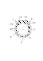
- the holding clips 2 and 2 have a C-shaped plan view as shown in FIG. 4, for example. Therefore, in the present embodiment, the holding clips are referred to as C clips 2 and 2.
- the specific structure of the stay guide 1 having a cylindrical shape in such a basic structure will be described.
- This material is made of a thermoplastic synthetic resin material such as polypropylene resin (PP) as shown in FIGS. 1, 2, and 3, for example, and has a cylindrical shape on the basis of such a synthetic resin material. Thus, it is molded.
- a stay pressing portion 15 formed in a strip shape in the axial direction is provided on a part of the outer peripheral surface of the stay guide 1 made of such a cylindrical body, for example, as shown in FIG. Yes.
- the strip-like stay pressing portion 15 is configured such that both ends in the longitudinal direction are integrally coupled to the surrounding cylindrical portion 11.
- a concave groove 12 is formed at a substantially central portion in the longitudinal direction of the strip-like stay pressing portion 15 and at an outer peripheral portion of the cylindrical stay guide 1 formed so as to hold the stay pressing portion 15. , 152 are provided. Further, a retaining clip having a 3/4 circular shape, that is, a C clip 2 is fitted in the concave grooves 12 and 152, for example, as shown in FIGS. Yes.
- the C clip 2 has a form of ohm ( ⁇ ) in plan view, and a wire such as a piano wire (SWP-B) is adopted as a material, and such a wire is bent and formed. Thus, it is formed in a predetermined form.
- the annular portion 22 formed to have a 3/4 circular arc length, and the annular portion 22 at both end portions of the annular portion 22. It is basically composed of guide portions 21 and 21 formed so as to open continuously in a C shape.
- the C-clip 2 has an annular portion 22 in the concave groove 12 provided in the stay guide 1 and in the concave groove 152 provided in the stay pressing portion 15. So that the stay pressing portion 15 is operated inward, that is, the stay pressing portion 15 is pressed against the surface side of the headrest stay 81. As a result, the headrest stays 81 and 81 are held at predetermined positions, and the generation of noise from around the stay guides 1 and 1 holding the headrest stays 81 and 81 can be prevented.
- the stay pressing portion 15 is placed at the guide portions 21 and 21 that are formed in a C shape and formed at the opening end of the C clip 2. Is inserted into the concave groove 152 provided in the stay guide 1 and further into the concave groove 12 provided in the stay guide 1 to be temporarily engaged. In such a state, the annular portion 22 of the C clip 2 is fitted into the concave groove 12 provided in the stay guide 1 and further into the concave groove 152 provided in the stay pressing portion 15. Push in like so. At this time, the holding portions 115 formed at a part of the cylindrical portion 11 provided in the stay guide 1 are replaced with the base portions 215 and 215 of the both guide portions 21 and 21 as shown in FIG.
- the pressing force to the outer peripheral surface side of the headrest stay 81 by the stay pressing portion 15 is securely held.
- the height of the headrest 8 can be adjusted smoothly.
- the generation of abnormal noise such as rattling from the headrest stays 81 and 81 is effective for vibration input to the headrest device. Will be deterred.
- the stay guides 1 and 1 having such a configuration are mounted on a hollow holder 3 provided in the upper part of the seat frame 5 as shown in FIG.
- the hollow holder 3 has a quadrangular cross-sectional shape, and such a square holder 3 is divided into two vertically. It is designed to be provided. That is, the holder 3 includes an upper holder 31 and a lower holder 32 as shown in FIG. 1, for example, so that the weight of the holder 3 can be reduced.
- the stay guide 1 is reliably held.
Landscapes
- Engineering & Computer Science (AREA)
- Aviation & Aerospace Engineering (AREA)
- Transportation (AREA)
- Mechanical Engineering (AREA)
- Seats For Vehicles (AREA)
- Chair Legs, Seat Parts, And Backrests (AREA)
Abstract
Priority Applications (2)
| Application Number | Priority Date | Filing Date | Title |
|---|---|---|---|
| US13/499,754 US8967721B2 (en) | 2009-10-05 | 2010-09-09 | Headrest support device |
| BR112012007852A BR112012007852A2 (pt) | 2009-10-05 | 2010-09-09 | dispositivo para suporte de apoio para cabeça |
Applications Claiming Priority (2)
| Application Number | Priority Date | Filing Date | Title |
|---|---|---|---|
| JP2009231240A JP5243381B2 (ja) | 2009-10-05 | 2009-10-05 | ヘッドレストサポート装置 |
| JP2009-231240 | 2009-10-05 |
Publications (1)
| Publication Number | Publication Date |
|---|---|
| WO2011043155A1 true WO2011043155A1 (fr) | 2011-04-14 |
Family
ID=43856633
Family Applications (1)
| Application Number | Title | Priority Date | Filing Date |
|---|---|---|---|
| PCT/JP2010/065499 Ceased WO2011043155A1 (fr) | 2009-10-05 | 2010-09-09 | Dispositif support d'appui-tête |
Country Status (4)
| Country | Link |
|---|---|
| US (1) | US8967721B2 (fr) |
| JP (1) | JP5243381B2 (fr) |
| BR (1) | BR112012007852A2 (fr) |
| WO (1) | WO2011043155A1 (fr) |
Families Citing this family (20)
| Publication number | Priority date | Publication date | Assignee | Title |
|---|---|---|---|---|
| DE112011100271B4 (de) | 2010-01-18 | 2014-09-18 | Lear Corporation | Sitzbaugruppe |
| JP5762179B2 (ja) * | 2011-07-03 | 2015-08-12 | 日本発條株式会社 | 車両用シート |
| EP2979583A1 (fr) * | 2013-03-28 | 2016-02-03 | Johnson Controls Technology Company | Siège pour véhicule |
| JP2016526507A (ja) * | 2013-06-29 | 2016-09-05 | サン−ゴバン パフォーマンス プラスティックス コーポレイション | 摺動するヘッドレストに使用されるベアリング |
| JP5814310B2 (ja) * | 2013-07-19 | 2015-11-17 | トヨタ自動車株式会社 | ヘッドレスト支持構造 |
| JP2015208438A (ja) * | 2014-04-25 | 2015-11-24 | トヨタ紡織株式会社 | 乗物用シート |
| WO2016097283A1 (fr) * | 2014-12-19 | 2016-06-23 | Saint-Gobain Performance Plastics Pampus Gmbh | Palier comportant des éléments coulissants séparés et appui-tête comprenant ledit palier |
| DE102015000108A1 (de) * | 2015-01-14 | 2016-07-14 | Grammer Ag | Lagervorrichtung und Kopfstütze |
| US10538185B2 (en) | 2015-03-16 | 2020-01-21 | Southco, Inc. | Friction module, friction hinge, and adjustable headrest including the friction module and/or friction hinge |
| JP6787914B2 (ja) * | 2015-03-16 | 2020-11-18 | サウスコ,インコーポレイティド | 摩擦モジュール、摩擦ヒンジ、および、摩擦モジュールおよび/または摩擦ヒンジを含む調整可能ヘッドレスト |
| CN107635828B (zh) * | 2015-06-11 | 2020-01-21 | 安道拓卢森堡控股有限公司 | 车辆座椅的导向套筒 |
| US10981480B2 (en) * | 2017-01-25 | 2021-04-20 | Ts Tech Co., Ltd. | Vehicle seat and cover member |
| US10099589B2 (en) * | 2017-02-21 | 2018-10-16 | Ts Tech Co., Ltd. | Headrest guide |
| WO2018178245A1 (fr) | 2017-03-31 | 2018-10-04 | Saint-Gobain Performance Plastics Pampus Gmbh | Anneau, procédé et ensemble de réglage de déplacement d'élément |
| US11378124B2 (en) | 2017-07-14 | 2022-07-05 | Saint-Gobain Performance Plastics Pampus Gmbh | Clip, clip assembly, and method of making and using the same |
| BR112020025227B1 (pt) * | 2018-06-11 | 2023-01-17 | Southco, Inc | Apoio de cabeça ajustável e módulo de fricção |
| US11135957B2 (en) * | 2019-03-20 | 2021-10-05 | Ami Industries, Inc. | Continuously adjusting headrest device |
| FR3122153B1 (fr) * | 2021-04-27 | 2023-05-05 | Tesca France | Procédé d’assemblage d’un dispositif de réception et de verrouillage en hauteur d’une tige de montage d’un appui-tête de siège de véhicule automobile |
| JP7799545B2 (ja) * | 2022-03-31 | 2026-01-15 | 日本発條株式会社 | ヘッドレスト支持部構造 |
| JP7750572B1 (ja) | 2024-08-27 | 2025-10-07 | 向陽技研株式会社 | 支持受け具およびこれを用いた支持構造 |
Citations (2)
| Publication number | Priority date | Publication date | Assignee | Title |
|---|---|---|---|---|
| JPH0313858U (fr) * | 1989-06-27 | 1991-02-13 | ||
| JPH11198703A (ja) * | 1998-01-12 | 1999-07-27 | Nippon Technica Kk | ヘッドレストサポート |
Family Cites Families (9)
| Publication number | Priority date | Publication date | Assignee | Title |
|---|---|---|---|---|
| DE19608851C2 (de) * | 1996-03-07 | 2001-09-13 | Opel Adam Ag | Aus Kunststoff bestehende Führungshülse für die Tragstange einer Kopfstütze |
| JP3475320B2 (ja) | 1997-09-24 | 2003-12-08 | 日本テクニカ株式会社 | ヘッドレストサポート |
| JP4352742B2 (ja) | 2003-03-31 | 2009-10-28 | 株式会社豊田自動織機 | 位置保持機構 |
| DE202004009769U1 (de) * | 2004-06-22 | 2005-11-17 | Itw Automotive Products Gmbh & Co. Kg | Kopfstützenhülse mit Toleranzausgleich |
| JP4854200B2 (ja) * | 2005-01-21 | 2012-01-18 | 日本テクニカ株式会社 | ヘッドレストサポート |
| JP5226945B2 (ja) | 2006-10-16 | 2013-07-03 | 日本テクニカ株式会社 | ステーと、ヘッドレストサポートの頭部におけるガタ防止機構を備えたヘッドレストサポート |
| JP5289751B2 (ja) | 2007-10-31 | 2013-09-11 | 日本テクニカ株式会社 | ガタ防止機構を備えたヘッドレストサポート |
| JP5242133B2 (ja) | 2007-11-06 | 2013-07-24 | 日本テクニカ株式会社 | ガタ防止機構を備えたヘッドレストサポート |
| JP5242139B2 (ja) | 2007-11-26 | 2013-07-24 | 日本テクニカ株式会社 | ガタ防止機構を備えたヘッドレストサポート |
-
2009
- 2009-10-05 JP JP2009231240A patent/JP5243381B2/ja not_active Expired - Fee Related
-
2010
- 2010-09-09 BR BR112012007852A patent/BR112012007852A2/pt not_active Application Discontinuation
- 2010-09-09 WO PCT/JP2010/065499 patent/WO2011043155A1/fr not_active Ceased
- 2010-09-09 US US13/499,754 patent/US8967721B2/en not_active Expired - Fee Related
Patent Citations (2)
| Publication number | Priority date | Publication date | Assignee | Title |
|---|---|---|---|---|
| JPH0313858U (fr) * | 1989-06-27 | 1991-02-13 | ||
| JPH11198703A (ja) * | 1998-01-12 | 1999-07-27 | Nippon Technica Kk | ヘッドレストサポート |
Also Published As
| Publication number | Publication date |
|---|---|
| US20120200135A1 (en) | 2012-08-09 |
| US8967721B2 (en) | 2015-03-03 |
| JP2012254648A (ja) | 2012-12-27 |
| JP5243381B2 (ja) | 2013-07-24 |
| BR112012007852A2 (pt) | 2016-03-15 |
Similar Documents
| Publication | Publication Date | Title |
|---|---|---|
| WO2011043155A1 (fr) | Dispositif support d'appui-tête | |
| KR101836503B1 (ko) | 헤드레스트 가이드 | |
| JP6770924B2 (ja) | グロメット | |
| US8662483B2 (en) | Shock absorber for vehicle seat | |
| EP2851238B1 (fr) | Dispositif de manchon pour appuie-tête | |
| US9994133B2 (en) | Headrest and mount therefor | |
| JP2010090906A (ja) | クリップ | |
| JP2001204577A (ja) | ヘッドレスト装置 | |
| JP4465782B2 (ja) | ヘッドレスト装置 | |
| EP2862479B1 (fr) | Structure de support d'appuie-tête | |
| WO2018168724A1 (fr) | Guide d'appui-tête et siège de véhicule | |
| JP6031185B2 (ja) | 乗り物用座席 | |
| US9403457B2 (en) | Headrest, vehicle seat | |
| CN103025578A (zh) | 头枕 | |
| KR20180070155A (ko) | 헤드레스트의 폴가이드 | |
| KR101683428B1 (ko) | 시트의 헤드레스트 가이드 조립체 | |
| US10518678B2 (en) | Headrest support structure | |
| JP2004298498A (ja) | 位置保持機構 | |
| JP5250054B2 (ja) | ヘッドレスト構造 | |
| JP2011000144A (ja) | ヘッドレスト支持装置 | |
| KR20200114344A (ko) | 헤드레스트 폴가이드 | |
| JP5286509B2 (ja) | ヘッドレストホルダー | |
| JP5227861B2 (ja) | ヘッドレスト支持構造及びシート | |
| KR200411330Y1 (ko) | 헤드레스트의 수평이동장치 | |
| KR200171656Y1 (ko) | 자동차용 헤드 레스트의 설치구조(Structure for mounting head rest of automobile) |
Legal Events
| Date | Code | Title | Description |
|---|---|---|---|
| 121 | Ep: the epo has been informed by wipo that ep was designated in this application |
Ref document number: 10821826 Country of ref document: EP Kind code of ref document: A1 |
|
| WWE | Wipo information: entry into national phase |
Ref document number: 13499754 Country of ref document: US |
|
| NENP | Non-entry into the national phase |
Ref country code: DE |
|
| WWE | Wipo information: entry into national phase |
Ref document number: 1201001547 Country of ref document: TH |
|
| 122 | Ep: pct application non-entry in european phase |
Ref document number: 10821826 Country of ref document: EP Kind code of ref document: A1 |
|
| NENP | Non-entry into the national phase |
Ref country code: JP |
|
| REG | Reference to national code |
Ref country code: BR Ref legal event code: B01A Ref document number: 112012007852 Country of ref document: BR |
|
| ENP | Entry into the national phase |
Ref document number: 112012007852 Country of ref document: BR Kind code of ref document: A2 Effective date: 20120405 |