WO2011043473A1 - Molten metal producing device - Google Patents
Molten metal producing device Download PDFInfo
- Publication number
- WO2011043473A1 WO2011043473A1 PCT/JP2010/067792 JP2010067792W WO2011043473A1 WO 2011043473 A1 WO2011043473 A1 WO 2011043473A1 JP 2010067792 W JP2010067792 W JP 2010067792W WO 2011043473 A1 WO2011043473 A1 WO 2011043473A1
- Authority
- WO
- WIPO (PCT)
- Prior art keywords
- raw material
- furnace
- layer
- metal
- molten
- Prior art date
- Legal status (The legal status is an assumption and is not a legal conclusion. Google has not performed a legal analysis and makes no representation as to the accuracy of the status listed.)
- Ceased
Links
Images


Classifications
-
- F—MECHANICAL ENGINEERING; LIGHTING; HEATING; WEAPONS; BLASTING
- F27—FURNACES; KILNS; OVENS; RETORTS
- F27B—FURNACES, KILNS, OVENS OR RETORTS IN GENERAL; OPEN SINTERING OR LIKE APPARATUS
- F27B3/00—Hearth-type furnaces, e.g. of reverberatory type; Electric arc furnaces ; Tank furnaces
- F27B3/08—Hearth-type furnaces, e.g. of reverberatory type; Electric arc furnaces ; Tank furnaces heated electrically, with or without any other source of heat
- F27B3/085—Arc furnaces
-
- C—CHEMISTRY; METALLURGY
- C21—METALLURGY OF IRON
- C21B—MANUFACTURE OF IRON OR STEEL
- C21B13/00—Making spongy iron or liquid steel, by direct processes
- C21B13/10—Making spongy iron or liquid steel, by direct processes in hearth-type furnaces
-
- C—CHEMISTRY; METALLURGY
- C21—METALLURGY OF IRON
- C21B—MANUFACTURE OF IRON OR STEEL
- C21B11/00—Making pig-iron other than in blast furnaces
- C21B11/10—Making pig-iron other than in blast furnaces in electric furnaces
-
- C—CHEMISTRY; METALLURGY
- C21—METALLURGY OF IRON
- C21B—MANUFACTURE OF IRON OR STEEL
- C21B13/00—Making spongy iron or liquid steel, by direct processes
- C21B13/02—Making spongy iron or liquid steel, by direct processes in shaft furnaces
- C21B13/023—Making spongy iron or liquid steel, by direct processes in shaft furnaces wherein iron or steel is obtained in a molten state
- C21B13/026—Making spongy iron or liquid steel, by direct processes in shaft furnaces wherein iron or steel is obtained in a molten state heated electrically
-
- C—CHEMISTRY; METALLURGY
- C21—METALLURGY OF IRON
- C21B—MANUFACTURE OF IRON OR STEEL
- C21B13/00—Making spongy iron or liquid steel, by direct processes
- C21B13/12—Making spongy iron or liquid steel, by direct processes in electric furnaces
-
- C—CHEMISTRY; METALLURGY
- C21—METALLURGY OF IRON
- C21C—PROCESSING OF PIG-IRON, e.g. REFINING, MANUFACTURE OF WROUGHT-IRON OR STEEL; TREATMENT IN MOLTEN STATE OF FERROUS ALLOYS
- C21C5/00—Manufacture of carbon-steel, e.g. plain mild steel, medium carbon steel or cast steel or stainless steel
- C21C5/56—Manufacture of steel by other methods
- C21C5/562—Manufacture of steel by other methods starting from scrap
-
- F—MECHANICAL ENGINEERING; LIGHTING; HEATING; WEAPONS; BLASTING
- F27—FURNACES; KILNS; OVENS; RETORTS
- F27B—FURNACES, KILNS, OVENS OR RETORTS IN GENERAL; OPEN SINTERING OR LIKE APPARATUS
- F27B3/00—Hearth-type furnaces, e.g. of reverberatory type; Electric arc furnaces ; Tank furnaces
- F27B3/08—Hearth-type furnaces, e.g. of reverberatory type; Electric arc furnaces ; Tank furnaces heated electrically, with or without any other source of heat
-
- F—MECHANICAL ENGINEERING; LIGHTING; HEATING; WEAPONS; BLASTING
- F27—FURNACES; KILNS; OVENS; RETORTS
- F27B—FURNACES, KILNS, OVENS OR RETORTS IN GENERAL; OPEN SINTERING OR LIKE APPARATUS
- F27B3/00—Hearth-type furnaces, e.g. of reverberatory type; Electric arc furnaces ; Tank furnaces
- F27B3/10—Details, accessories or equipment, e.g. dust-collectors, specially adapted for hearth-type furnaces
- F27B3/18—Arrangements of devices for charging
-
- F—MECHANICAL ENGINEERING; LIGHTING; HEATING; WEAPONS; BLASTING
- F27—FURNACES; KILNS; OVENS; RETORTS
- F27B—FURNACES, KILNS, OVENS OR RETORTS IN GENERAL; OPEN SINTERING OR LIKE APPARATUS
- F27B3/00—Hearth-type furnaces, e.g. of reverberatory type; Electric arc furnaces ; Tank furnaces
- F27B3/10—Details, accessories or equipment, e.g. dust-collectors, specially adapted for hearth-type furnaces
- F27B3/22—Arrangements of air or gas supply devices
- F27B3/225—Oxygen blowing
-
- F—MECHANICAL ENGINEERING; LIGHTING; HEATING; WEAPONS; BLASTING
- F27—FURNACES; KILNS; OVENS; RETORTS
- F27D—DETAILS OR ACCESSORIES OF FURNACES, KILNS, OVENS OR RETORTS, IN SO FAR AS THEY ARE OF KINDS OCCURRING IN MORE THAN ONE KIND OF FURNACE
- F27D25/00—Devices or methods for removing incrustations, e.g. slag, metal deposits, dust; Devices or methods for preventing the adherence of slag
-
- F—MECHANICAL ENGINEERING; LIGHTING; HEATING; WEAPONS; BLASTING
- F27—FURNACES; KILNS; OVENS; RETORTS
- F27D—DETAILS OR ACCESSORIES OF FURNACES, KILNS, OVENS OR RETORTS, IN SO FAR AS THEY ARE OF KINDS OCCURRING IN MORE THAN ONE KIND OF FURNACE
- F27D3/00—Charging; Discharging; Manipulation of charge
- F27D3/04—Ram or pusher apparatus
-
- F—MECHANICAL ENGINEERING; LIGHTING; HEATING; WEAPONS; BLASTING
- F27—FURNACES; KILNS; OVENS; RETORTS
- F27D—DETAILS OR ACCESSORIES OF FURNACES, KILNS, OVENS OR RETORTS, IN SO FAR AS THEY ARE OF KINDS OCCURRING IN MORE THAN ONE KIND OF FURNACE
- F27D3/00—Charging; Discharging; Manipulation of charge
- F27D3/16—Introducing a fluid jet or current into the charge
-
- C—CHEMISTRY; METALLURGY
- C21—METALLURGY OF IRON
- C21B—MANUFACTURE OF IRON OR STEEL
- C21B13/00—Making spongy iron or liquid steel, by direct processes
- C21B13/006—Starting from ores containing non ferrous metallic oxides
-
- C—CHEMISTRY; METALLURGY
- C22—METALLURGY; FERROUS OR NON-FERROUS ALLOYS; TREATMENT OF ALLOYS OR NON-FERROUS METALS
- C22B—PRODUCTION AND REFINING OF METALS; PRETREATMENT OF RAW MATERIALS
- C22B7/00—Working up raw materials other than ores, e.g. scrap, to produce non-ferrous metals and compounds thereof; Methods of a general interest or applied to the winning of more than two metals
- C22B7/02—Working-up flue dust
-
- Y—GENERAL TAGGING OF NEW TECHNOLOGICAL DEVELOPMENTS; GENERAL TAGGING OF CROSS-SECTIONAL TECHNOLOGIES SPANNING OVER SEVERAL SECTIONS OF THE IPC; TECHNICAL SUBJECTS COVERED BY FORMER USPC CROSS-REFERENCE ART COLLECTIONS [XRACs] AND DIGESTS
- Y02—TECHNOLOGIES OR APPLICATIONS FOR MITIGATION OR ADAPTATION AGAINST CLIMATE CHANGE
- Y02P—CLIMATE CHANGE MITIGATION TECHNOLOGIES IN THE PRODUCTION OR PROCESSING OF GOODS
- Y02P10/00—Technologies related to metal processing
- Y02P10/20—Recycling
Definitions
- the present invention relates to a molten metal production apparatus for producing molten metal by reducing and melting a bulk metal raw material such as a carbonaceous material-incorporated metal oxide agglomerate directly in an electric heating melting furnace such as an arc furnace without preliminary reduction. .
- the carbonized metal oxide agglomerates are pre-reduced in a rotary hearth furnace to form a solid reduced metal, which is then used as an arc furnace or submerged arc furnace.
- Various molten metal production processes have been proposed in which molten metal is obtained by melting with (see, for example, Patent Documents 1 to 4).
- the conventional process requires a configuration consisting of two steps of a preliminary reduction step using a rotary hearth furnace and a melting step using a melting furnace. Along with this, it is necessary to transfer solid reduced metal from the rotary hearth furnace to the melting furnace, and the exhaust gas treatment system also requires two systems, the rotary hearth furnace and the melting furnace. As a result, in addition to the increase in equipment cost, there is a problem that heat loss is large and the energy intensity cannot be sufficiently reduced.
- the molten metal manufacturing apparatus has the raw material charging chutes 4, 4 at both ends 2, 2 in the furnace width direction and the electrode 5 at the center in the furnace width direction.
- a stationary non-tilting electric heating furnace in which a secondary combustion burner 6 is installed in a flat furnace upper part 1, but here an arc furnace is used, and the carbon material A is charged in advance from the chutes 4 and 4 to form the electrode 5.
- a charcoal packed bed 12 having a downward slope facing downward is formed, and then a charcoal-containing metal oxide agglomerate B is charged and the charcoal packed bed (corresponding to the “raw material packed bed” of the present invention) 12.
- An agglomerate layer (corresponding to the “bulk metal raw material layer” of the present invention) 13 is formed on the slope, and then the electrode 5 is subjected to arc heating to sequentially melt the lower end of the agglomerate layer 13 into the furnace.
- the molten metal layer 14 and the molten slag layer 15 are formed, and the agglomerate layer 13 is filled with carbon
- the CO-containing gas generated from the agglomerate layer 13 is combusted by the oxygen-containing gas C blown from the secondary combustion burner 6 while being lowered along the 12 slope, and the agglomerate layer 13 is heated by the radiant heat. It is characterized by doing.
- the CO-containing gas generated from the agglomerate layer is moved to the secondary combustion burner while moving the agglomerate layer toward the electrode along the slope of the raw material packed layer formed in the furnace. It burns with the oxygen-containing gas blown from, heats the agglomerate layer itself with its radiant heat, preliminarily reduces, and this prereduced agglomerate layer is reduced and melted by arc heating near the electrode to melt Since it is made of metal, molten metal can be obtained directly from the carbonized metal oxide agglomerate in a single process, and both the equipment cost and the energy intensity can be greatly reduced compared to the conventional method.
- An object of the present invention is to provide an apparatus for producing molten metal that can be eliminated.
- an exhaust gas duct and a raw material charging chute are connected to an upper portion of a stationary non-tilting electric furnace having electric heating means, and the raw material charging chute is at one end of the furnace width.
- the electric heating means is installed so that an electric heating region heated by the electric heating means exists at the other end of the furnace width, and a secondary combustion burner is installed at the upper part of the furnace.
- a raw material packed bed having a downward slope from one end of the furnace width to the electric heating region, with a predetermined amount of carbonaceous material and / or bulk metal raw material being charged into the furnace in advance from the raw material charging chute Then, a bulk metal raw material is continuously or intermittently charged from the raw material charging chute to form a bulk metal raw material layer on the slope of the raw material packed layer, and then the electric heating Electric heating by means By sequentially melting the massive metal raw material in the vicinity of the lower end of the massive metal raw material layer, a molten metal layer and a molten slag layer are formed in the furnace, and the massive metal raw material layer is formed along the slope of the raw material packed layer.
- a molten metal production apparatus for producing a molten metal by heating and reducing a massive metal raw material layer, wherein the massive metal raw material layer is above the molten slag layer and in the furnace below the surface of the massive metal raw material layer.
- a molten metal production apparatus provided with a shock generating device for mechanically eliminating shelf hanging of a metal raw material layer.
- an exhaust gas duct and a raw material charging chute are connected to an upper portion of a stationary non-tilting electric furnace having electric heating means, and the raw material charging chute is provided at both end portions in the furnace width direction.
- the electric heating means is installed so that an electric heating region heated by the electric heating means exists in the center of the furnace width, and a secondary combustion burner is installed in the upper part of the furnace.
- a predetermined amount of carbonaceous material and / or bulk metal raw material is charged into the furnace from raw material charging chutes installed at both ends in the furnace width direction, and the electric heating region is supplied from both ends in the furnace width direction.
- a raw material packed layer having a slope with a downward slope is formed, and then a bulk metal raw material is charged continuously or intermittently from raw material charging chutes installed at both ends in the furnace width direction, and the raw material Bulk gold on the slope of the packed bed
- a molten metal layer and a molten slag layer are formed in the furnace by forming a raw material layer and then electrically heating with the electric heating means to sequentially melt the massive metal raw material near the lower end of the massive metal raw material layer.
- a molten metal production apparatus for producing a molten metal by combusting a CO-containing gas generated from the massive metal raw material layer and heating the massive metal raw material layer with its radiant heat, wherein the molten metal production device is above the surface of the molten slag layer.
- a shock generator for mechanically eliminating shelf hanging of the massive metal material layer is provided in the furnace below the surface of the massive metal material layer.
- the shock is generated.
- An apparatus is provided between a height position from the lowest position of the raw material charging chute to 1/3 below the distance between the lowermost end of the raw material charging chute and the surface of the molten slag layer. Also good.
- the shock generating device may be composed of a shaft portion having a rotation axis along the furnace longitudinal direction and a crushing member projecting on the surface thereof.
- the shock generator rotates around the rotation axis only in the direction in which the massive metal raw material layer is lowered, or alternately rotates in the direction in which the massive metal raw material layer is lowered and in the opposite direction. May be.
- the shock generator is arranged so that the shaft portion is present in the raw material packed layer or the massive metal raw material layer, and at least a part of the crushing member is in contact with the massive metal raw material layer. Also good.
- the shock generating device may be provided between a height position from the surface of the molten slag layer to 1/3 above the distance between the surface of the molten slag layer and the lowest end of the raw material charging chute.
- a shock generator is provided in the furnace above the molten slag layer and below the surface of the massive metal material layer, that is, in the massive metal material layer or the material packed layer. It is possible to apply external force directly to the massive metal raw material layer or indirectly via the raw material packed layer by continuous or intermittent operation of the apparatus, and it is possible to effectively prevent shelf hanging from occurring in the massive metal raw material layer. At the same time, even if shelves are generated, shelves can be quickly and reliably eliminated without stopping the operation of the molten metal production apparatus.
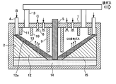
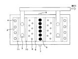
- FIGS. 1A and 1B show a schematic configuration of a molten metal production apparatus according to an embodiment of the present invention.
- the apparatus according to the present embodiment has the same apparatus configuration as the molten metal manufacturing apparatus according to the above-mentioned prior application invention shown in FIGS. 2A and 2B except for a shock generator 18 described later.
- the stationary non-tilting electric furnace electric furnace (hereinafter sometimes simply referred to as “furnace”) according to the present embodiment is an arc furnace having a substantially rectangular horizontal cross section, and the furnace upper part (in this example, the furnace upper part). 1), an exhaust gas duct 3 and a plurality of raw material charging chutes 4 are connected, and a plurality of electrodes 5 are inserted into the furnace via the furnace upper part 1.
- the raw material charging chute 4 is installed at both ends 2 and 2 in the furnace width direction, while the electrode 5 is installed at the center in the furnace width direction.
- a plurality of secondary combustion burners 6 are provided at the furnace upper part (furnace upper part 1 in this example).
- the inside of the furnace above the surface of the molten slag layer 15 and below the surface of the massive metal raw material layer 13, that is, in the massive metal raw material layer 13 or the raw material filling A shock generator 18 is provided in the layer 12 to mechanically eliminate the shelf hanging of the massive metal raw material layer 13.
- the “shock generating device” refers to a device that applies external force to the massive metal raw material layer 13 continuously or intermittently.
- the shock generator 18 is operated directly or intermittently by operating the shock generator 18 continuously or intermittently. Since an external force can be applied indirectly through the raw material packed layer 12, it is possible to prevent shelf hanging from occurring in the bulk metal raw material layer 13, and even if shelf hanging has occurred, molten metal production apparatus The shelf suspension can be eliminated quickly and reliably without stopping the operation.
- the shock generator 18 is installed in the furnace above the surface of the molten slag layer 15 and below the surface of the massive metal raw material layer 13, that is, anywhere in the massive metal raw material layer 13 or the raw material packed layer 12. Although a certain shelf-hanging prevention effect can be obtained, the bulk metal raw material B charged into the furnace from the raw material charging chute 4 has a particle diameter of 90% or less of the average particle diameter of the entire bulk metal raw material B. In the case where 2% by mass or more of the small particles having slag are included, the shock generator 18 is moved from the height position of the lowest end of the raw material charging chute 4 to the lowest end of the raw material charging chute 4 and the surface of the molten slag layer 15 It is recommended that it be provided between the height positions up to 1/3 below the distance.
- the raw material charging chute is introduced when the massive metal raw material B is charged into the furnace from the raw material charging chute 4. Small particles are likely to be deposited in the vicinity of 4 and the small particles are metalized and fixed as soon as they are heated in the furnace, so that shelf hanging is likely to occur near the raw material charging chute 4.
- shock generator 18 at a height just below the raw material charging chute 4, it is possible to effectively prevent shelf hanging caused by the accumulation of small grains without reducing the production yield of the bulk metal raw material B. Will be able to.
- the shock generator 18 includes, for example, a shaft portion 18a having a rotating shaft along the longitudinal direction of the furnace and a plurality of crushing members 18b protruding on the surface thereof (Midrex method direct reduction shaft furnace furnace. It is possible to use a barden feeder that is installed inside and used for preventing shelves of reduced iron from being suspended. And it can prevent that shelf hanging generate
- the shock generator 18 approximated to the above-mentioned Baden feeder has a direction in which the massive metal raw material layer 13 is lowered around its rotational axis (normal). It is only necessary to appropriately select one that rotates only in the direction), or one that rotates alternately in the direction in which the massive metal raw material layer 13 is lowered (forward direction) and the opposite direction.
- the former places importance on transport, and the latter places importance on crushing.
- a shock generator 18 (comprising a shaft portion 18a having a rotation axis along the furnace longitudinal direction and a plurality of crushing members 18b projecting on the surface thereof) similar to the Baden feeder is above the molten slag layer 15.
- the shaft portion 18a is present in the raw material filling layer 12 or the massive metal raw material layer 13, and at least a part of the crushing member 18b is disposed so as to be in contact with the massive metal raw material layer 13. It is recommended that you do this.
- shock generator 18 similar to the Baden feeder has a height from the surface of the molten slag layer 15 to 1/3 above the distance between the surface of the molten slag layer 15 and the lowermost end of the raw material charging chute 4. Recommended between positions.
- partition walls 9, 10, 11 is preferably provided between the electrode 5 and the secondary combustion burner 6, between the secondary combustion burner 6 and the exhaust gas duct 3, and between the exhaust gas duct 3 and the raw material charging chute 4.
- the partition wall 10 be provided between the secondary combustion burner 6 and the exhaust gas duct 3 to prevent the exhaust gas after the secondary combustion from being short-cut to the exhaust gas duct 3, This is to ensure a sufficient amount of radiant heat transfer to 13.
- the partition walls 9, 10, 11 may be installed entirely or a part of them may be installed by comprehensively considering the degree of each effect described above, installation cost, maintenance labor, etc. It may be.
- the exhaust gas duct 3 is preferably installed on the side closer to the raw material charging chute 4 than the electrode 5. This is to prevent the oxidizing exhaust gas after the secondary combustion from flowing toward the electrode 5 and damaging the electrode 5.
- the raw material charging chute 4 is not provided in the lower part of the furnace (that is, the raw material packed layer 12 is not formed in the furnace), and the tap hole 7 and the tap hole 8 Are preferably provided. This is for facilitating the hole opening operation at the time of tapping.
- a known heat exchanger (not shown) may be installed on the downstream side of the exhaust gas duct 3, thereby recovering the sensible heat of the high-temperature exhaust gas discharged from the furnace, and oxygen for the secondary combustion burner It can be used effectively as energy for preheating the contained gas, generating electric power for arc, drying pellet B, and the like.
- the electrode 5 for example, a three-phase AC type that is excellent in thermal efficiency and is commonly used in an arc electric furnace for steelmaking is recommended. And, for example, it is recommended to adopt a configuration in which six electrodes are made from three sets of single-phase electrodes formed by combinations of two phases of three-phase electrodes.
- the electrode 5 is subjected to a melting operation while its tip is positioned (immersed) in the bulk metal raw material layer 13 or the molten slag layer 15.
- the effects of radiant heating and resistance heating by the arc can coexist, melting can be further promoted, and damage to the furnace wall inner surface not protected by the raw material packed bed 12 can be suppressed.
- molten iron is produced as a molten metal using this stationary non-tilting arc furnace
- a carbonaceous material-containing pellet is used as a packed bed forming raw material for forming a raw material packed layer in the furnace
- a carbonaceous material-containing iron oxide pellet is also used as a massive metal raw material laminated on the raw material packed layer.
- a carbonaceous material interior oxidation that is a predetermined amount of a bulk metal raw material as a raw material for forming a packed bed from raw material charging chutes 4 and 4 previously installed at both ends 2 and 2 in the furnace width direction.
- An iron pellet A is charged into the furnace to form a raw material packed layer 12 having a slope 12a having a downward slope extending from both ends 2 and 2 in the furnace width direction toward the lower side of the lower end of the electrode 5 in advance.
- carbonaceous iron-incorporated iron oxide pellets (hereinafter simply referred to as “carbonized iron-incorporated metal oxide agglomerates” from the raw material charging chutes 4 and 4 installed at both ends 2 and 2 in the furnace width direction as a bulk metal raw material.
- pellet. carbonaceous iron-incorporated metal oxide agglomerates
- the blending amount of the interior carbon material in the pellet B may be determined by adding the target C concentration of molten iron to the theoretical C amount necessary for reducing iron oxide to metallic iron.
- the pellet B is preferably dried in advance so as not to burst (bursting) when entering the furnace interior.
- the height of the electrode 5 is preferably adjusted in advance so that the lower end of the electrode 5 is immersed in the pellet layer 13.
- the electrode is energized and subjected to arc heating, whereby the pellet B in the vicinity of the lower end of the pellet layer 13 is rapidly heated and sequentially reduced and melted, and separated into molten iron and molten slag as molten metal,
- the molten iron layer 14 and the molten slag layer 15 are formed in the lower part.
- a CaO source such as limestone or dolomite or an MgO source in advance to the pellet B.
- the pellets B are sequentially melted from the vicinity of the lower end portion of the pellet layer 13.
- the pellet layer 13 itself is caused by its own weight, and further, using the material transfer function of the shock generator 18, the material filling is performed.
- the inside of the furnace is sequentially lowered along the slope of the layer toward the lower end of the electrode 5.
- the pellet B in the pellet layer 13 approaches the electrode 5, it is efficiently heated by the radiant heat and resistance heating by the arc from the electrode 5, and the iron oxide in the pellet B is preliminarily turned into solid metallic iron by the interior carbon material. While being reduced, a CO-containing gas (combustible gas) is generated.
- a carbon material containing volatile components such as coal is used as the interior carbon material, the volatile components devolatilized from the interior carbon material by heating are also added to the CO-containing gas.
- This CO-containing gas is combusted by, for example, oxygen gas (secondary combustion) as an oxygen-containing gas blown from a secondary combustion burner 6 provided in the upper part 1 of the furnace, and is radiated by the combustion (secondary combustion). Also, the pellet layer 13 is heated. In this way, the pellet layer 13 heated by radiant heat is pre-reduced to solid metal iron and the CO-containing gas in the same manner as in the case of radiant heating by the arc from the electrode 5 and resistance heating. Therefore, the radiant heating by the secondary combustion is further promoted.
- oxygen gas secondary combustion
- the pellet layer 13 heated by radiant heat is pre-reduced to solid metal iron and the CO-containing gas in the same manner as in the case of radiant heating by the arc from the electrode 5 and resistance heating. Therefore, the radiant heating by the secondary combustion is further promoted.
- the pellet B charged into the furnace from the raw material charging chute 4 descends on the slope 12a of the raw material packed bed 12 while being radiated by the secondary combustion (hereinafter referred to as “secondary”). It is also referred to as “combustion heat”.) Is preliminarily reduced to a high metalization rate in a solid state, and then melted by arc heating and resistance heating in the vicinity of the lower end portion of the electrode 5 to be separated into molten iron and molten slag.
- the iron oxide concentration in the molten slag generated in the vicinity of the lower end of the electrode 5 becomes sufficiently low, and wear of the electrode 5 can be suppressed.
- the molten iron separated from the molten slag dissolves the carbonaceous material remaining in the pellet B and becomes a molten iron having a target C concentration.
- the molten iron and molten slag generated in this way can be intermittently discharged from the tap hole 7 and the tap hole 8 provided in the lower part of the furnace, for example, in the same manner as in the blast furnace.
- the shock generator 18 is an apparatus of a type that applies an external force to the massive metal raw material layer 13 by rotational movement around the rotation axis, and is similar to a Baden feeder (shaft portion 18a and projecting on the surface thereof)
- the present invention is not limited to this, and any material can be used as long as an external force can be applied continuously or intermittently to the bulk metal raw material layer 13. It can also be used with any type of device.
- a device for example, a screw
- a device for example, a pusher
- a device that applies external force by pressure for example, a device that blows gas directly into the furnace or a device that deforms a diaphragm by gas pressure
- a device that applies external force by pressure for example, a device that blows gas directly into the furnace or a device that deforms a diaphragm by gas pressure
- the electrode 5 is the furnace width direction of the furnace upper part 1
- the electrode 5 may be installed at the other end 2 of the furnace width.
- the example in which the electrode 5 is installed on the center line of the furnace width is shown as an example of installing the electrode 5 on the center part in the furnace width direction.
- the present invention is not limited to this, and it is allowed to be installed by being shifted from the center line of the furnace width toward either end of the furnace width.
- the exhaust gas duct 3 and the raw material charging chute 4 are both connected to the furnace upper part 1.
- the present invention is not limited to this example. You may make it connect to upper part.
- the raw material charging chute 4 is automatically installed at the end of the furnace width.
- the substantially rectangular thing was illustrated as a horizontal cross-sectional shape of a stationary non-tilting type arc furnace, it is not limited to this,
- the thing of a substantially ellipse or a perfect circle is used. May be.
- scale-up can be easily performed by extending the furnace longitudinal direction (direction perpendicular to the furnace width direction) while keeping the furnace width constant.
- the pellet was illustrated as a form of the carbonaceous material interior metal oxide agglomerate B, you may employ
- the briquette has a larger angle of repose than the spherical pellet, so in order to ensure the residence time on the inclined surface 12a of the raw material packed bed 12, it is necessary to increase the furnace height compared to the case of using the pellet, There is an advantage that the furnace width can be reduced.
- Charcoal interior containing metal scrap iron scrap
- reduced metal reduced iron [DRI, HBI]
- bulk metal oxide ore bulk metal oxide ore
- metal chloride instead of pellets and charcoal interior iron oxide briquettes
- Metal chloride agglomerates and metal oxide agglomerates may be used, carbonaceous material interior metal oxide agglomerates, metal scrap, reduced metal
- One or more selected from the group consisting of a massive metal oxide ore, a carbonaceous material-incorporated metal chloride agglomerate, and a metal oxide agglomerated mineral may be used.
- a volatile metal other than a non-volatile metal element was illustrated. It may contain elements such as Zn and Pb. That is, as the carbonaceous material-incorporated metal oxide agglomerate B, steel mill dust containing a volatile metal element can be used as the metal oxide raw material.
- the volatile metal element is heated in the furnace and volatilized and removed from the carbonaceous material-containing metal oxide agglomerate B.
- the temperature of the upper part of the furnace is increased by the combustion heat from the secondary combustion burner 6. Since it can be kept sufficiently high, the volatile metal element that has been volatilized and removed is reliably prevented from re-condensing in the upper part of the furnace, and the volatile metal element is efficiently recovered from the exhaust gas discharged from the furnace. Can do.
- the volatile metal element means a metal element having a melting point of 1100 ° C. or less at 1 atm of a compound such as a simple metal or a salt thereof.
- a compound such as a simple metal or a salt thereof.
- the metal simple substance include zinc and lead.
- the volatile metal element compound include sodium chloride and potassium chloride.
- Volatile metals in the volatile metal element compound are reduced to metals in an electric furnace (for example, an arc furnace, a submerged arc furnace), and a part or all of them are in a gaseous state in the furnace.
- the chloride of the volatile metal element is heated in the electric furnace, and a part or all of the chloride exists in the gaseous state in the furnace.
- the non-volatile metal element means a metal element having a melting point at 1 atm of a metal simple substance or a compound such as an oxide thereof exceeding 1100 ° C.
- the metal simple substance include iron, nickel, cobalt, chromium, titanium and the like.
- the non-volatile metal oxide include CaO, SiO2, and Al2O3.
- iron Fe
- Fe Fe
- the carbonaceous material interior metal oxide agglomerate B as a lump metal raw material
- the molten metal 14, Ni, Mn, Cr other than Fe Nonferrous metals such as may be contained.
- the means which adds a CaO source and a MgO source previously to carbonaceous material interior metal oxide agglomerate B was illustrated as a basicity adjustment means of molten slag, it replaced with or added to this means
- the raw material charging chute 4 may be charged with limestone or dolomite together with the carbonaceous material-incorporated metal oxide agglomerate B, or separately from the carbonaceous material-incorporated metal oxide agglomerate B with a separately provided chute. You may make it enter.
- the carbonaceous material interior iron oxide pellet was illustrated as a filling layer formation raw material which forms the raw material filling layer 12, you may use another lump metal raw material, and use 2 or more types of them together May be.
- a carbon material such as coal or coke may be used instead of or in addition to the bulk metal raw material.
- the particle size of the carbon material-containing iron oxide pellets B is such that the carbon material-containing iron oxide pellets B do not sink into the voids of the raw material packed layer 12 as the raw material packed layer. It is good to adjust according to.
- the tap hole 7 and the tap hole 8 are separately installed on the opposite side walls, but both may be installed on the same side wall side, or It is also possible to omit the dredging hole 8 and install only the dredging hole 7 and discharge the molten iron and molten slag from the dredging hole 7.
Landscapes
- Engineering & Computer Science (AREA)
- Chemical & Material Sciences (AREA)
- Mechanical Engineering (AREA)
- General Engineering & Computer Science (AREA)
- Materials Engineering (AREA)
- Organic Chemistry (AREA)
- Metallurgy (AREA)
- Manufacturing & Machinery (AREA)
- Vertical, Hearth, Or Arc Furnaces (AREA)
- Manufacture And Refinement Of Metals (AREA)
- Manufacture Of Iron (AREA)
- Furnace Charging Or Discharging (AREA)
- Furnace Details (AREA)
Abstract
Description
本発明は、炭材内装酸化金属塊成化物などの塊状金属原料を、予備還元することなく、直接、アーク炉などの電気加熱溶解炉で還元溶融して溶融金属を製造する溶融金属製造装置に関する。 The present invention relates to a molten metal production apparatus for producing molten metal by reducing and melting a bulk metal raw material such as a carbonaceous material-incorporated metal oxide agglomerate directly in an electric heating melting furnace such as an arc furnace without preliminary reduction. .
従来の高炉法や溶融還元法に代わる新しい製鉄法として、炭材内装酸化金属塊成化物を回転炉床炉で予備還元して固体還元金属とし、この固体還元金属をアーク炉またはサブマージドアーク炉で溶解して溶融金属を得る溶融金属製造プロセスが種々提案されている(例えば、特許文献1~4参照)。
As a new iron-making method that replaces the conventional blast furnace method and smelting reduction method, the carbonized metal oxide agglomerates are pre-reduced in a rotary hearth furnace to form a solid reduced metal, which is then used as an arc furnace or submerged arc furnace. Various molten metal production processes have been proposed in which molten metal is obtained by melting with (see, for example,
しかしながら、従来のプロセスは、回転炉床炉による予備還元工程と溶解炉による溶解工程の2工程からなる構成を必須としている。これに伴い、回転炉床炉から溶解炉への固体還元金属の移送手段が必要となることや、排ガス処理系統も回転炉床炉と溶解炉の2系統が必要となることなどにより、トータルプロセスとして、設備コストが高くなることに加え、熱ロスも大きく、エネルギ原単位も十分に低減できない問題があった。 However, the conventional process requires a configuration consisting of two steps of a preliminary reduction step using a rotary hearth furnace and a melting step using a melting furnace. Along with this, it is necessary to transfer solid reduced metal from the rotary hearth furnace to the melting furnace, and the exhaust gas treatment system also requires two systems, the rotary hearth furnace and the melting furnace. As a result, in addition to the increase in equipment cost, there is a problem that heat loss is large and the energy intensity cannot be sufficiently reduced.
そこで、本発明者は、回転炉床炉を用いることなく、電気式加熱炉だけで、炭材内装酸化金属塊成化物を還元するとともに溶解して溶融金属を製造する具体的方法について種々検討を実施した結果、以下の発明を完成させるに至り、既に特許出願を行った(日本国特願2009-105397号;以下、本特許出願に係る発明を「先願発明」という。)。 Therefore, the present inventor has made various studies on specific methods for producing molten metal by reducing and melting carbonaceous material-containing metal oxide agglomerates using only an electric heating furnace without using a rotary hearth furnace. As a result of the implementation, the following invention has been completed, and a patent application has already been filed (Japanese Patent Application No. 2009-105397; hereinafter, the invention according to this patent application will be referred to as “prior application invention”).
上記先願発明に係る溶融金属製造装置は、図2A及び2Bに示すように、原料装入シュート4,4を炉幅方向の両端部2,2に、電極5を炉幅方向の中央部に、平面状の炉上部1に二次燃焼バーナ6をそれぞれ設置した定置式非傾動型電気式加熱炉ただしここではアーク炉を用い、予めシュート4,4から炭材Aを装入して電極5下方に向かう下り斜面を有する炭材充填層12を形成しておき、次いで炭材内装酸化金属塊成化物Bを装入して炭材充填層(本願発明の「原料充填層」に相当)12斜面上に塊成化物層(本願発明の「塊状金属原料層」に相当)13を形成し、その後電極5にてアーク加熱を行い塊成化物層13下端部を順次溶融して、炉内に溶融金属層14と溶融スラグ層15を形成するとともに、塊成化物層13を炭材充填層12斜面に沿って降下させつつ、二次燃焼バーナ6から吹込んだ酸素含有ガスCで、塊成化物層13から発生するCO含有ガスを燃焼させ、その放射熱により塊成化物層13を加熱することを特徴とするものである。
As shown in FIGS. 2A and 2B, the molten metal manufacturing apparatus according to the above-mentioned prior application invention has the raw material charging chutes 4, 4 at both
上記先願発明によれば、炉内に形成した原料充填層の斜面に沿って塊成化物層を電極に向かって移動させつつ、該塊成化物層から発生したCO含有ガスを二次燃焼バーナから吹き込んだ酸素含有ガスで燃焼し、その放射熱で該塊成化物層自身を加熱して予備還元し、この予備還元された塊成化物層を上記電極近傍でアーク加熱により還元溶融して溶融金属とするので、単一の工程にて、炭材内装酸化金属塊成化物から直接溶融金属が得られ、従来法に比べて設備コストおよびエネルギ原単位がともに大幅に低減できるようになった。 According to the prior invention, the CO-containing gas generated from the agglomerate layer is moved to the secondary combustion burner while moving the agglomerate layer toward the electrode along the slope of the raw material packed layer formed in the furnace. It burns with the oxygen-containing gas blown from, heats the agglomerate layer itself with its radiant heat, preliminarily reduces, and this prereduced agglomerate layer is reduced and melted by arc heating near the electrode to melt Since it is made of metal, molten metal can be obtained directly from the carbonized metal oxide agglomerate in a single process, and both the equipment cost and the energy intensity can be greatly reduced compared to the conventional method.
しかしながら、上記先願発明に係る溶融金属製造装置では、炉に装入する塊成化物に粉が多く含まれている場合や、炉内で塊成化物どうしが焼結したり融着したりした場合には、塊成化物層の棚吊りが生じてその円滑な降下が阻害され、塊成化物を適切に加熱し還元し溶解することができなくなり装置の性能が低下する懸念が残されていた。そして、上記のような塊成化物層の棚吊りが生じた際には、上記先願発明に係る溶融金属製造装置では、炉の操業を停止することなく棚吊りを解消することは不可能であった。 However, in the molten metal production apparatus according to the invention of the prior application, when the agglomerate charged into the furnace contains a large amount of powder, the agglomerates were sintered or fused in the furnace. In some cases, the agglomerate layer was suspended from the shelves and the smooth descent was hindered, and the agglomerate could not be properly heated, reduced, and dissolved, and there was a concern that the performance of the apparatus would deteriorate. . And when the above-mentioned agglomerate layer shelf suspension occurs, in the molten metal manufacturing apparatus according to the above-mentioned prior application, it is impossible to eliminate the shelf suspension without stopping the operation of the furnace. there were.
そこで、本発明は、炉内で塊状金属原料層の棚吊りが発生することを効果的に予防するとともに、万一棚吊りが発生してしまった場合でも操業を停止することなく、これを確実に解消しうる溶融金属製造装置を提供することを目的とする。 Therefore, the present invention effectively prevents the shelf hanging of the massive metal raw material layer in the furnace, and ensures this even if the shelf suspension occurs, without stopping the operation. An object of the present invention is to provide an apparatus for producing molten metal that can be eliminated.
本発明の第1の態様は、電気加熱手段を有する定置式非傾動型電気炉の炉上部に排ガスダクトと原料装入シュートとが接続されるとともに、前記原料装入シュートは炉幅の片端部に設置される一方、前記電気加熱手段は、該電気加熱手段で加熱される電気加熱領域が炉幅の他端部に存在するように設置されるとともに、炉上部に二次燃焼バーナが設置され、予め、前記原料装入シュートから炭材および/または塊状金属原料を所定量炉内に装入して、前記炉幅の片端部から前記電気加熱領域に向かう下り勾配の斜面を有する原料充填層を形成しておき、次いで、前記原料装入シュートから塊状金属原料を連続的または間欠的に装入して、前記原料充填層の斜面上に塊状金属原料層を形成し、その後、前記電気加熱手段にて電気加熱を行って、前記塊状金属原料層の下端部近傍の塊状金属原料を順次溶融することにより、炉内に溶融金属層と溶融スラグ層を形成するとともに、前記塊状金属原料層を前記原料充填層の斜面に沿って降下させつつ、前記二次燃焼バーナから前記塊状金属原料層より上方の炉内空間部に酸素含有ガスを吹き込んで、前記塊状金属原料層から発生するCO含有ガスを燃焼させ、その放射熱により前記塊状金属原料層を加熱し還元することにより溶融金属を製造する溶融金属製造装置であって、前記溶融スラグ層より上方で、かつ、前記塊状金属原料層の表面より下方の炉内に、該塊状金属原料層の棚吊りを機械的に解消するためのショック発生装置を設けたことを特徴とする溶融金属製造装置を提供する。 According to a first aspect of the present invention, an exhaust gas duct and a raw material charging chute are connected to an upper portion of a stationary non-tilting electric furnace having electric heating means, and the raw material charging chute is at one end of the furnace width. On the other hand, the electric heating means is installed so that an electric heating region heated by the electric heating means exists at the other end of the furnace width, and a secondary combustion burner is installed at the upper part of the furnace. A raw material packed bed having a downward slope from one end of the furnace width to the electric heating region, with a predetermined amount of carbonaceous material and / or bulk metal raw material being charged into the furnace in advance from the raw material charging chute Then, a bulk metal raw material is continuously or intermittently charged from the raw material charging chute to form a bulk metal raw material layer on the slope of the raw material packed layer, and then the electric heating Electric heating by means By sequentially melting the massive metal raw material in the vicinity of the lower end of the massive metal raw material layer, a molten metal layer and a molten slag layer are formed in the furnace, and the massive metal raw material layer is formed along the slope of the raw material packed layer. While lowering, oxygen-containing gas is blown from the secondary combustion burner into the space in the furnace above the massive metal material layer to burn the CO-containing gas generated from the massive metal material layer, A molten metal production apparatus for producing a molten metal by heating and reducing a massive metal raw material layer, wherein the massive metal raw material layer is above the molten slag layer and in the furnace below the surface of the massive metal raw material layer. There is provided a molten metal production apparatus provided with a shock generating device for mechanically eliminating shelf hanging of a metal raw material layer.
本発明の第2の態様は、電気加熱手段を有する定置式非傾動型電気炉の炉上部に排ガスダクトと原料装入シュートとを接続するとともに、原料装入シュートは、炉幅方向の両端部にそれぞれ設置される一方、前記電気加熱手段は、該電気加熱手段で加熱される電気加熱領域が炉幅の中央部に存在するように設置されるとともに、炉上部に二次燃焼バーナが設置され、予め、前記炉幅方向の両端部に設置した原料装入シュートから炭材および/または塊状金属原料を所定量炉内に装入して、該炉幅方向の両端部から前記電気加熱領域に向かう下り勾配の斜面を有する原料充填層を形成しておき、次いで、前記炉幅方向の両端部に設置した原料装入シュートから塊状金属原料を連続的または間欠的に装入して、前記原料充填層の斜面上に塊状金属原料層を形成し、その後、前記電気加熱手段にて電気加熱を行って、前記塊状金属原料層の下端部近傍の塊状金属原料を順次溶融することにより、炉内に溶融金属層と溶融スラグ層を形成するとともに、前記塊状金属原料層を前記原料充填層の斜面に沿って降下させつつ、前記二次燃焼バーナから前記塊状金属原料層より上方の炉内空間部に酸素含有ガスを吹き込んで、前記塊状金属原料層から発生するCO含有ガスを燃焼させ、その放射熱により前記塊状金属原料層を加熱することにより溶融金属を製造する溶融金属製造装置であって、前記溶融スラグ層の表面より上方で、かつ、前記塊状金属原料層の表面より下方の炉内に、該塊状金属原料層の棚吊りを機械的に解消するためのショック発生装置を設けたことを特徴とする溶融金属製造装置を提供する。 According to a second aspect of the present invention, an exhaust gas duct and a raw material charging chute are connected to an upper portion of a stationary non-tilting electric furnace having electric heating means, and the raw material charging chute is provided at both end portions in the furnace width direction. On the other hand, the electric heating means is installed so that an electric heating region heated by the electric heating means exists in the center of the furnace width, and a secondary combustion burner is installed in the upper part of the furnace. In addition, a predetermined amount of carbonaceous material and / or bulk metal raw material is charged into the furnace from raw material charging chutes installed at both ends in the furnace width direction, and the electric heating region is supplied from both ends in the furnace width direction. A raw material packed layer having a slope with a downward slope is formed, and then a bulk metal raw material is charged continuously or intermittently from raw material charging chutes installed at both ends in the furnace width direction, and the raw material Bulk gold on the slope of the packed bed A molten metal layer and a molten slag layer are formed in the furnace by forming a raw material layer and then electrically heating with the electric heating means to sequentially melt the massive metal raw material near the lower end of the massive metal raw material layer. And bubbling oxygen-containing gas from the secondary combustion burner into the space in the furnace above the massive metal material layer while lowering the massive metal material layer along the slope of the material packed layer, A molten metal production apparatus for producing a molten metal by combusting a CO-containing gas generated from the massive metal raw material layer and heating the massive metal raw material layer with its radiant heat, wherein the molten metal production device is above the surface of the molten slag layer. In addition, a shock generator for mechanically eliminating shelf hanging of the massive metal material layer is provided in the furnace below the surface of the massive metal material layer. To provide a device.
前記原料装入シュートから炉内に装入される塊状金属原料が、該塊状金属原料全体の平均粒径の90%以下の粒径を有する小粒を2質量%以上含む場合には、前記ショック発生装置を、前記原料装入シュートの最下端の高さ位置から、該原料装入シュートの最下端と前記溶融スラグ層の表面との距離の1/3下方までの高さ位置の間に設けてもよい。 When the bulk metal raw material charged into the furnace from the raw material charging chute contains 2% by mass or more of small particles having a particle size of 90% or less of the average particle size of the entire bulk metal raw material, the shock is generated. An apparatus is provided between a height position from the lowest position of the raw material charging chute to 1/3 below the distance between the lowermost end of the raw material charging chute and the surface of the molten slag layer. Also good.
前記ショック発生装置が、炉長手方向に沿う回転軸を有するシャフト部と、その表面に突設された解砕部材からなるものであってもよい。 The shock generating device may be composed of a shaft portion having a rotation axis along the furnace longitudinal direction and a crushing member projecting on the surface thereof.
前記ショック発生装置は、前記回転軸回りに、前記塊状金属原料層を降下させる方向にのみ回転するもの、または、前記塊状金属原料層を降下させる方向とその逆方向に交互に回転するものであってもよい。 The shock generator rotates around the rotation axis only in the direction in which the massive metal raw material layer is lowered, or alternately rotates in the direction in which the massive metal raw material layer is lowered and in the opposite direction. May be.
前記シャフト部が前記原料充填層内または前記塊状金属原料層内に存在し、かつ、前記解砕部材の少なくとも一部が前記塊状金属原料層に接触するように、前記ショック発生装置を配置してもよい。 The shock generator is arranged so that the shaft portion is present in the raw material packed layer or the massive metal raw material layer, and at least a part of the crushing member is in contact with the massive metal raw material layer. Also good.
前記ショック発生装置を、前記溶融スラグ層の表面から、該溶融スラグ層の表面と原料装入シュートの最下端との距離の1/3上方までの高さ位置の間に設けてもよい。 The shock generating device may be provided between a height position from the surface of the molten slag layer to 1/3 above the distance between the surface of the molten slag layer and the lowest end of the raw material charging chute.
本発明によれば、溶融スラグ層より上方で、かつ、塊状金属原料層の表面より下方の炉内、すなわち塊状金属原料層内または原料充填層内にショック発生装置を設けたことで、ショック発生装置の連続的または間欠的運転により塊状金属原料層に直接または原料充填層を介して間接的に外力を加えることが可能となり、塊状金属原料層に棚吊りが発生することを効果的に予防できるとともに、たとえ棚吊りが発生してしまったとしても溶融金属製造装置の操業を停止することなく迅速かつ確実に棚吊りを解消できるようになった。 According to the present invention, a shock generator is provided in the furnace above the molten slag layer and below the surface of the massive metal material layer, that is, in the massive metal material layer or the material packed layer. It is possible to apply external force directly to the massive metal raw material layer or indirectly via the raw material packed layer by continuous or intermittent operation of the apparatus, and it is possible to effectively prevent shelf hanging from occurring in the massive metal raw material layer. At the same time, even if shelves are generated, shelves can be quickly and reliably eliminated without stopping the operation of the molten metal production apparatus.
以下、本発明の実施の形態を図面に基づいて詳細に説明する。 Hereinafter, embodiments of the present invention will be described in detail with reference to the drawings.
図1A及び1Bに、本発明の一実施形態に係る溶融金属製造装置の概略構成を示す。本実施形態に係る装置は、後述のショック発生装置18を除いて、図2A及び2Bに示す上記先願発明に係る溶融金属製造装置と装置構成が共通する。
1A and 1B show a schematic configuration of a molten metal production apparatus according to an embodiment of the present invention. The apparatus according to the present embodiment has the same apparatus configuration as the molten metal manufacturing apparatus according to the above-mentioned prior application invention shown in FIGS. 2A and 2B except for a
すなわち、本実施形態に係る定置式非傾動型電気炉電気炉(以下、単に「炉」ということもある。)は水平断面形状が略矩形のアーク炉であり、炉上部(本例では炉上部1)には、排ガスダクト3および複数の原料装入シュート4が接続されるとともに、炉内には炉上部1を介して複数本の電極5が挿入されている。原料装入シュート4は、炉幅方向の両端部2,2にそれぞれ設置される一方、電極5は、炉幅方向の中央部に設置されている。さらに、炉上部(本例では炉上部1)には、複数本の二次燃焼バーナ6が設けられている。
That is, the stationary non-tilting electric furnace electric furnace (hereinafter sometimes simply referred to as “furnace”) according to the present embodiment is an arc furnace having a substantially rectangular horizontal cross section, and the furnace upper part (in this example, the furnace upper part). 1), an
そして、上記先願発明に係る溶融金属製造装置と異なり、溶融スラグ層15の表面より上方で、かつ、塊状金属原料層13の表面より下方の炉内、つまり塊状金属原料層13内または原料充填層12内に、該塊状金属原料層13の棚吊りを機械的に解消するためのショック発生装置18が設けられている。ここに、「ショック発生装置」とは、塊状金属原料層13に連続的または間欠的に外力を加える装置をいう。
And, unlike the molten metal production apparatus according to the above-mentioned prior application, the inside of the furnace above the surface of the
このように、塊状金属原料層13内または原料充填層12内にショック発生装置18を設けたことで、ショック発生装置18を連続的または間欠的に運転することにより塊状金属原料層13に直接または原料充填層12を介して間接的に外力を加えることができるので、塊状金属原料層13に棚吊りが発生することを予防できるとともに、たとえ棚吊りが発生してしまったとしても溶融金属製造装置の操業を停止することなく迅速かつ確実に棚吊りを解消できる。
Thus, by providing the
ショック発生装置18は、溶融スラグ層15の表面より上方で、かつ、塊状金属原料層13の表面より下方の炉内、つまり塊状金属原料層13内または原料充填層12内のどこに設置しても一定の棚吊り防止効果が得られるものであるが、原料装入シュート4から炉内に装入される塊状金属原料Bが、該塊状金属原料B全体の平均粒径の90%以下の粒径を有する小粒を2質量%以上含む場合には、ショック発生装置18を、原料装入シュート4の最下端の高さ位置から、該原料装入シュート4の最下端と溶融スラグ層15の表面との距離の1/3下方までの高さ位置の間に設けるのが推奨される。
The
これにより、原料装入シュート4直下近傍での小粒の堆積に起因する棚吊りを効果的に防止することができる。 Thereby, it is possible to effectively prevent the shelf hanging due to the accumulation of small particles immediately below the raw material charging chute 4.
すなわち、炉内に装入される塊状金属原料Bが粉などの小粒を多量に含んでいると、塊状金属原料Bが原料装入シュート4から炉内に装入された際に原料装入シュート4直下近傍に小粒が堆積しやすく、また、小粒は炉内で加熱されるとすぐに金属化し固着するので、原料装入シュート4直下近傍で棚吊りが発生しやすくなる。 That is, if the massive metal raw material B charged in the furnace contains a large amount of small particles such as powder, the raw material charging chute is introduced when the massive metal raw material B is charged into the furnace from the raw material charging chute 4. Small particles are likely to be deposited in the vicinity of 4 and the small particles are metalized and fixed as soon as they are heated in the furnace, so that shelf hanging is likely to occur near the raw material charging chute 4.
このような問題を回避する手段として、塊状金属原料Bをたとえば事前に篩などで分級して狭い粒度範囲に完全に調整してから炉内に装入することが考えられるが、このような手段を採用すると、炉内での棚吊りの問題は回避できるものの、塊状金属原料Bの製造歩留りが低下するので、結果的には溶融金属の製造コスト問題が上昇してしまうという別の問題が生じてしまう。 As a means for avoiding such a problem, it is conceivable to classify the bulk metal raw material B with a sieve or the like in advance and completely adjust it to a narrow particle size range before charging it into the furnace. However, the problem of shelf hanging in the furnace can be avoided, but the production yield of the bulk metal raw material B decreases, resulting in another problem that the production cost of molten metal increases. End up.
そこで、原料装入シュート4直下近傍の高さ位置にショック発生装置18を設置することで、塊状金属原料Bの製造歩留りを低下させることなく、小粒の堆積に起因する棚吊りを効果的に防止することができることとなる。
Therefore, by installing the
このショック発生装置18としては、例えば、炉長手方向に沿う回転軸を有するシャフト部18aと、その表面に突設された複数の解砕部材18bからなるもの(Midrex法直接還元用シャフト炉の炉内に設置され、還元鉄の棚吊り防止のために用いられるバーデンフィーダ[burdenfeeder]に近似したもの)を用いることができる。そして、ショック発生装置18のシャフト部18aを連続的または一定時間ごとに間欠的に回転させることにより、塊状金属原料層13に棚吊りが発生するのを防止することができる。万一塊状金属原料層13に棚吊りが発生してしまった場合でも、シャフト部18aに突設された複数の解砕部材18bで塊状金属原料Bどうしの焼結物や融着物を解砕する、あるいは解砕が十分でない場合でも上記焼結物や融着物が巨大化する前に強制的に電極5の下方に向かって移送(降下)させることができるので、円滑な操業を長期にわたって継続することができる。
The
このような作用を棚吊りの発生状況等に応じて有効に発揮させるため、上記バーデンフィーダに近似したショック発生装置18としては、その回転軸回りに、塊状金属原料層13を降下させる方向(正方向)にのみ回転するもの、または、塊状金属原料層13を降下させる方向(正方向)とその逆方向に交互に回転するものを適宜選択すればよい。なお、前者は移送を重視し、後者は解砕を重視するものである。
In order to effectively exhibit such an action according to the state of occurrence of shelf hanging, etc., the
上記バーデンフィーダに近似したショック発生装置18(炉長手方向に沿う回転軸を有するシャフト部18aと、その表面に突設された複数の解砕部材18bからなるもの)は、溶融スラグ層15より上方で、かつ、塊状金属原料層13の表面より下方の炉内、すなわち塊状金属原料層13内または原料充填層12内であれば、いずれの位置に設置しても一定の棚吊り防止効果が得られるものであるが、特に、シャフト部18aが原料充填層12内または塊状金属原料層13内に存在し、かつ、解砕部材18bの少なくとも一部が塊状金属原料層13に接触するように配置するのが推奨される。
A shock generator 18 (comprising a
これにより、シャフト部18aの回転に伴って解砕部材18bが塊状金属原料層13に直接的に外力を加えることとなるので、より効率的に棚吊りを防止できる。
Thereby, since the crushing
また、上記バーデンフィーダに近似したショック発生装置18は、溶融スラグ層15の表面から、該溶融スラグ層15の表面と原料装入シュート4の最下端との距離の1/3上方までの高さ位置の間に設けるのが推奨される。
Further, the
このように、塊状金属原料の金属化が進行し軟化して棚吊りが発生しやすくなる高さ位置に上記バーデンフィーダに近似したショック発生装置18を配置することで、より効率的な棚吊り防止効果を得ることができる。
In this way, by placing the
電極5と二次燃焼バーナ6との間、二次燃焼バーナ6と排ガスダクト3との間、排ガスダクト3と原料装入シュート4との間には、炉内に垂下する隔壁9,10,11を設けるのが好ましい。
Between the
電極5と二次燃焼バーナ6との間に隔壁9を設けるのが推奨されるのは、二次燃焼後の酸化性排ガスが電極5に接触するのを防止するためである。
It is recommended to provide the
また、二次燃焼バーナ6と排ガスダクト3との間に隔壁10を設けるのが推奨されるのは、二次燃焼後の排ガスが排ガスダクト3へショートカットするのを防止して、塊状金属原料層13への放射伝熱量を十分に確保するためである。
In addition, it is recommended that the
また、排ガスダクト3と原料装入シュート4との間に隔壁11を設けるのが推奨されるのは、原料装入シュート4が高温の排ガスで過熱されて損傷するのを防止するためである。
Also, it is recommended to provide the
隔壁9,10,11は、設置による上記各効果の度合い、設置コスト、メンテナンスの手間等を総合的に勘案して、その全部を設置するようにしてもよいし、その一部を設置するようにしてもよい。
The
また、排ガスダクト3は、電極5より原料装入シュート4に近い側に設置するのが好ましい。二次燃焼後の酸化性の排ガスが電極5の方に流れて電極5を損傷するのを抑制するためである。
The
そして、炉下部には、原料装入シュート4が設けられていない(すなわち、炉内に原料充填層12が形成されていない)炉長手側の炉側壁に、出銑孔7と出滓孔8とを設けるのが好ましい。出銑滓の際における開孔作業を容易にするためである。
And, the raw material charging chute 4 is not provided in the lower part of the furnace (that is, the raw material packed
また、排ガスダクト3の下流側には、周知の熱交換器(図示せず)を設置すればよく、これにより炉から排出された高温排ガスの顕熱を回収して、二次燃焼バーナ用酸素含有ガスの予熱や、アーク用電力の発電やペレットBの乾燥等のエネルギとして有効利用することができる。
Further, a known heat exchanger (not shown) may be installed on the downstream side of the
電極5としては、例えば、熱効率に優れた、製鋼用アーク電気炉で常用される三相交流型のものが推奨される。そして例えば、三相電極の各2相の組合せでできる3組の単相電極から電極6本を作るという構成を採用するのが推奨される。
As the
また、電極5は、その先端部を塊状金属原料層13または溶融スラグ層15中に位置させ(浸漬させ)つつ、溶解操作を行うのが好ましい。これにより、アークによる放射加熱と抵抗加熱の効果を並存させることができ、溶解をより促進することができるとともに、原料充填層12で保護されていない炉壁内面の損傷を抑制することができる。
Further, it is preferable that the
以下、この定置式非傾動型アーク炉を使用して、溶融金属として溶鉄を製造する場合を例に挙げて説明する。本例では、炉内に原料充填層を形成するための充填層形成用原料として炭材内装ペレットを、該原料充填層上に積層する塊状金属原料として同じく炭材内装酸化鉄ペレットをそれぞれ用いる。 Hereinafter, the case where molten iron is produced as a molten metal using this stationary non-tilting arc furnace will be described as an example. In this example, a carbonaceous material-containing pellet is used as a packed bed forming raw material for forming a raw material packed layer in the furnace, and a carbonaceous material-containing iron oxide pellet is also used as a massive metal raw material laminated on the raw material packed layer.
溶融金属の製造方法としては、予め、上記炉幅方向の両端部2,2に設置された原料装入シュート4,4から充填層形成用原料として所定量の塊状金属原料である炭材内装酸化鉄ペレットAを炉内に装入して、該炉幅方向の両端部2,2から電極5の下端部の下方に向かう下り勾配の斜面12aを有する原料充填層12を形成しておく。原料充填層12を形成する原料として炭材に代えて炭材内装酸化鉄ペレットなどの塊状金属原料を用いても、溶鉄との接触部分においては還元・溶融ないしは浸炭・溶解が進行するものの、該溶鉄との接触部分から離れた部分には熱が伝わりにくく、塊状金属原料は固体状態に維持されるため、一旦形成された原料充填層12は長期間充填層状態に保たれる。また、原料充填層12内の温度は上記溶鉄との接触部分から離れて炉壁に近づくほど低下するので、溶融FeOの形成による耐火物の損傷も問題とならない。
As a method for producing a molten metal, a carbonaceous material interior oxidation that is a predetermined amount of a bulk metal raw material as a raw material for forming a packed bed from raw material charging chutes 4 and 4 previously installed at both ends 2 and 2 in the furnace width direction. An iron pellet A is charged into the furnace to form a raw material packed
次いで、上記炉幅方向の両端部2,2に設置された原料装入シュート4,4から塊状金属原料としての炭材内装酸化金属塊成化物である炭材内装酸化鉄ペレット(以下、単に「ペレット」ともいう。)Bを連続的または間欠的に装入して、原料充填層12の斜面12a上に塊状金属原料層としてのペレット層13を形成する。ペレットB中の内装炭材の配合量は、酸化鉄が金属鉄まで還元されるに必要な理論C量に、溶鉄の目標C濃度を加味して決定するとよい。なお、ペレットBは、炉内装入時に爆裂(バースティング)しないように、事前に乾燥しておくのが好ましい。
Next, carbonaceous iron-incorporated iron oxide pellets (hereinafter simply referred to as “carbonized iron-incorporated metal oxide agglomerates” from the raw material charging chutes 4 and 4 installed at both ends 2 and 2 in the furnace width direction as a bulk metal raw material. Also referred to as “pellets.”) B is charged continuously or intermittently to form a
電極5は、上述のごとく、その下端部がペレット層13中に浸漬された状態となるように、予め高さを調節しておくとよい。
As described above, the height of the
その後、前記電極に通電してアーク加熱を行うことにより、ペレット層13の下端部近傍のペレットBが急速に加熱されて順次還元溶融し、溶融金属としての溶鉄と溶融スラグとに分離され、炉下部に溶鉄層14と溶融スラグ層15を形成する。なお、溶融スラグ層15の塩基度等を調整するため、ペレットB中には、予め石灰石やドロマイトなどのCaO源やMgO源を添加しておくのが好ましい。
Thereafter, the electrode is energized and subjected to arc heating, whereby the pellet B in the vicinity of the lower end of the
上記のようにして、ペレット層13の下端部近傍からペレットBが順次溶融されていく、ペレット層13自体はその自重により、さらにはショック発生装置18の原料移送機能を利用して、前記原料充填層の斜面に沿って電極5の下端部に向かって炉内を順次降下していくこととなる。
As described above, the pellets B are sequentially melted from the vicinity of the lower end portion of the
そして、ペレット層13中のペレットBが電極5に近づくと、電極5からのアークによる放射熱と抵抗加熱により効率的に加熱され、ペレットB中の酸化鉄が内装炭材により固体金属鉄に予備還元されるとともに、CO含有ガス(可燃性ガス)を生成する。内装炭材として石炭など揮発分を含有する炭材を用いた場合は、加熱により内装炭材から脱揮された揮発分も該CO含有ガスに加わる。
And when the pellet B in the
このCO含有ガスは、炉上部1に設けられた二次燃焼バーナ6から吹込まれた酸素含有ガスとしての例えば酸素ガスにより燃焼(二次燃焼)され、その燃焼(二次燃焼)による放射熱によってもペレット層13は加熱される。このように放射熱にて加熱されたペレット層13は、上記電極5からのアークによる放射加熱と抵抗加熱による場合と同様、ペレット中の酸化鉄が固体金属鉄に予備還元されるとともにCO含有ガスを生成するので、上記二次燃焼による放射加熱がさらに促進されることとなる。
This CO-containing gas is combusted by, for example, oxygen gas (secondary combustion) as an oxygen-containing gas blown from a
上記のようにして、原料装入シュート4から炉内に装入されたペレットBは、原料充填層12の斜面12a上を降下する間に、上記二次燃焼による放射加熱(以下、「二次燃焼熱」ともいう。)により固体状態で高金属化率まで予備還元された後、電極5下端部近傍でアーク加熱および抵抗加熱により溶融し、溶鉄と溶融スラグとに分離されることとなる。
As described above, the pellet B charged into the furnace from the raw material charging chute 4 descends on the
したがって、電極5下端部近傍に生成する溶融スラグ中の酸化鉄濃度は十分に低くなり、電極5の損耗を抑制することができる。
Therefore, the iron oxide concentration in the molten slag generated in the vicinity of the lower end of the
溶融スラグと分離された溶鉄は、ペレットB中に残存する炭材を溶解して目標C濃度の溶鉄となる。 The molten iron separated from the molten slag dissolves the carbonaceous material remaining in the pellet B and becomes a molten iron having a target C concentration.
このようにして生成した、溶鉄と溶融スラグは、炉下部に設けた出銑孔7と出滓孔8から、例えば高炉の出銑滓方法と同様にして、間欠的に排出することができる。
The molten iron and molten slag generated in this way can be intermittently discharged from the
上記実施形態では、ショック発生装置18として、回転軸回りの回転運動により塊状金属原料層13に外力を加える形式の装置である、バーデンフィーダに近似したもの(シャフト部18aと、その表面に突設された複数の解砕部材18bからなるもの)を例示したが、これに限定されるものではなく、塊状金属原料層13に連続的または間欠的に外力を加えることができるものであればいずれの形式の装置でも採用することができる。例えば、回転軸回りの回転運動により外力を加える形式の装置(例えばスクリュ)を用いてもよいし、シリンダ等の往復運動により外力を加える形式の装置(例えばプッシャ)を用いてもよいし、ガス圧により外力を加える形式の装置(例えば、ガスを炉内に直接吹き込む装置やガス圧によりダイヤフラムを変形させる装置)を用いてもよい。
In the above embodiment, the
また、上記実施形態では、原料装入シュート4および電極5の配置に関し、原料装入シュート4を炉幅方向の両端部2,2にそれぞれ設置する一方、電極5を炉上部1の炉幅方向の中央部に設置する例を示したが、原料装入シュート4を炉幅の片端部2に設置する一方、電極5を炉幅の他端部2に設置するようにしてもよい。本変形例を採用すると、炉内に形成される原料充填層12の斜面が片側だけになるので、上記実施例に比べて、耐火物保護の観点からは不利になるが、炉幅が縮小され、設備のコンパクト化が図れるメリットがある。なお、上記実施形態では、電極5を炉幅方向の中央部に設置する一例として、電極5を炉幅の中心線上に設置する例を示したが、必ずしも厳密に炉幅の中心線上に設置することに限定されるものではなく、炉幅の中心線上から炉幅のいずれかの端部の方へずらして設置することも許容される。
Moreover, in the said embodiment, regarding arrangement | positioning of the raw material charging chute 4 and the
また、上記実施形態では、排ガスダクト3と原料装入シュート4は、いずれも炉上部1に接続する例を示したが、これに限定されるものではなく、いずれか一方または双方を炉側壁の上部に接続するようにしてもよい。なお、原料装入シュート4を炉側壁の上部に接続した場合は、原料装入シュート4は自動的に炉幅の端部に設置されることになる。
In the above embodiment, the
また、上記実施形態では、定置式非傾動型アーク炉の水平断面形状として、略矩形のものを例示したが、これに限定されるものではなく、例えば略楕円のものや真円のものを用いてもよい。この場合単相電極でなく、三相電源の各相を用いて3本の電極を作るように構成してもよい。ただし、略矩形のものを用いた場合、炉幅は一定にしておいて、炉長手方向(炉幅方向に垂直な方向)を延長することで、スケールアップを容易に行えるメリットがある。 Moreover, in the said embodiment, although the substantially rectangular thing was illustrated as a horizontal cross-sectional shape of a stationary non-tilting type arc furnace, it is not limited to this, For example, the thing of a substantially ellipse or a perfect circle is used. May be. In this case, you may comprise so that three electrodes may be made using each phase of a three-phase power supply instead of a single phase electrode. However, when a substantially rectangular one is used, there is an advantage that scale-up can be easily performed by extending the furnace longitudinal direction (direction perpendicular to the furnace width direction) while keeping the furnace width constant.
また、上記実施形態では、炭材内装酸化金属塊成化物Bの形態として、ペレットを例示したが、ブリケットを採用してもよい。ブリケットは、球状のペレットより安息角が大きいので、原料充填層12の斜面12a上における滞留時間を確保するためには、ペレットを用いた場合に比べて、炉高は高くする必要があるものの、炉幅は縮小できるメリットがある。
Moreover, in the said embodiment, although the pellet was illustrated as a form of the carbonaceous material interior metal oxide agglomerate B, you may employ | adopt a briquette. The briquette has a larger angle of repose than the spherical pellet, so in order to ensure the residence time on the
また、上記実施形態では、塊状金属原料として炭材内装酸化金属塊成化物(炭材内装酸化鉄ペレット)のみを用いる例を示したが、炭材内装酸化金属塊成化物(炭材内装酸化鉄ペレット、炭材内装酸化鉄ブリケット)に代えて、金属スクラップ(鉄スクラップ)、還元金属(還元鉄[DRI、HBI])、塊状酸化金属鉱石(塊状鉄鉱石)、塩化金属を含有する炭材内装塩化金属塊成化物および酸化金属塊成鉱(焼成酸化鉄ペレット、コールドボンド酸化鉄ペレット、酸化鉄焼結鉱)を用いてもよいし、炭材内装酸化金属塊成化物、金属スクラップ、還元金属、塊状酸化金属鉱石、炭材内装塩化金属塊成化物および酸化金属塊成鉱よりなる群から選択される1種以上を用いてもよい。 Moreover, in the said embodiment, although the example using only a carbonaceous material interior metal oxide agglomerate (carbon material interior iron oxide pellet) was shown as a lump metal raw material, a carbon material interior metal oxide agglomerate (carbon material interior iron oxide) was shown. Charcoal interior containing metal scrap (iron scrap), reduced metal (reduced iron [DRI, HBI]), bulk metal oxide ore (bulk iron ore), metal chloride instead of pellets and charcoal interior iron oxide briquettes Metal chloride agglomerates and metal oxide agglomerates (calcined iron oxide pellets, cold bond iron oxide pellets, iron oxide sinter) may be used, carbonaceous material interior metal oxide agglomerates, metal scrap, reduced metal One or more selected from the group consisting of a massive metal oxide ore, a carbonaceous material-incorporated metal chloride agglomerate, and a metal oxide agglomerated mineral may be used.
また、上記実施形態では、炭材内装酸化金属塊成化物Bとして、非揮発性の金属元素である鉄のみを含有するものを例示したが、非揮発性の金属元素の他、揮発性の金属元素、例えば、Zn、Pbを含有するものであってもよい。すなわち、炭材内装酸化金属塊成化物Bとして、揮発性の金属元素を含有する製鉄所ダストなどを酸化金属原料として用いることができる。揮発性の金属元素は、炉内で加熱されて炭材内装酸化金属塊成化物Bから揮発除去されるが、本発明方法の採用により、二次燃焼バーナ6による燃焼熱によって炉上部の温度を十分に高く保持できるので、揮発除去された該揮発性金属元素が、炉上部で再凝縮することが確実に防止され、炉から排出された排ガスから該揮発性金属元素を効率的に回収することができる。
Moreover, in the said embodiment, although what contained only iron which is a non-volatile metal element was illustrated as carbonaceous material interior metal oxide agglomerate B, a volatile metal other than a non-volatile metal element was illustrated. It may contain elements such as Zn and Pb. That is, as the carbonaceous material-incorporated metal oxide agglomerate B, steel mill dust containing a volatile metal element can be used as the metal oxide raw material. The volatile metal element is heated in the furnace and volatilized and removed from the carbonaceous material-containing metal oxide agglomerate B. By adopting the method of the present invention, the temperature of the upper part of the furnace is increased by the combustion heat from the
なお、本明細書において、揮発性金属元素とは金属単体またはその塩等の化合物の1気圧での融点が1100℃以下の金属元素をいう。金属単体として例えば、亜鉛、鉛等を挙げることができる。揮発性金属元素の化合物として例えば塩化ナトリウム、塩化カリウム等を挙げることができる。揮発性金属元素の化合物中の揮発性金属は、電気炉(例えば、アーク炉、サブマージドアーク炉)で金属に還元されることで、その一部またはすべてが炉内で気体状態で存在する。また、揮発性金属元素の塩化物は、電気炉内で加熱されて、その一部またはすべてが炉内で気体状態で存在する。一方、非揮発性金属元素とは金属単体またはその酸化物等の化合物の1気圧での融点が1100℃を超える金属元素をいう。金属単体として例えば、鉄、ニッケル、コバルト、クロム、チタン等を挙げることができる。非揮発性金属の酸化物として、例えば、CaO、SiO2、Al2O3等を挙げることができる。非揮発性金属元素の化合物は、電気炉としてアーク炉やサブマージドアーク炉を用いたときには、炉内での加熱や還元反応によって、還元された金属単体としてまたは還元されない化合物として、炉内アーク近傍(アーク温度領域)では気体状態で存在できるものの、アークから離れたところでは液体または固体状態で存在する。 In this specification, the volatile metal element means a metal element having a melting point of 1100 ° C. or less at 1 atm of a compound such as a simple metal or a salt thereof. Examples of the metal simple substance include zinc and lead. Examples of the volatile metal element compound include sodium chloride and potassium chloride. Volatile metals in the volatile metal element compound are reduced to metals in an electric furnace (for example, an arc furnace, a submerged arc furnace), and a part or all of them are in a gaseous state in the furnace. In addition, the chloride of the volatile metal element is heated in the electric furnace, and a part or all of the chloride exists in the gaseous state in the furnace. On the other hand, the non-volatile metal element means a metal element having a melting point at 1 atm of a metal simple substance or a compound such as an oxide thereof exceeding 1100 ° C. Examples of the metal simple substance include iron, nickel, cobalt, chromium, titanium and the like. Examples of the non-volatile metal oxide include CaO, SiO2, and Al2O3. When using an arc furnace or submerged arc furnace as an electric furnace, a non-volatile metal element compound is used as a reduced metal element or as a non-reduced compound by heating or reduction reaction in the furnace. Although it can exist in a gas state in the (arc temperature region), it exists in a liquid or solid state away from the arc.
また、上記実施形態では、塊状金属原料としての炭材内装酸化金属塊成化物Bおよび溶融金属14を構成する金属元素として鉄(Fe)のみを例示したが、Feの他、Ni、Mn、Cr等の非鉄金属を含有してもよい。
Moreover, in the said embodiment, although only iron (Fe) was illustrated as a metal element which comprises the carbonaceous material interior metal oxide agglomerate B as a lump metal raw material, and the
また、上記実施形態では、溶融スラグの塩基度調整手段として、炭材内装酸化金属塊成化物Bに予めCaO源やMgO源を添加しておく手段を例示したが、この手段に代えてまたは加えて、原料装入シュート4から炭材内装酸化金属塊成化物Bとともに石灰石やドロマイトを装入するようにしてもよいし、別途設けたシュートから炭材内装酸化金属塊成化物Bとは別に装入するようにしてもよい。 Moreover, in the said embodiment, although the means which adds a CaO source and a MgO source previously to carbonaceous material interior metal oxide agglomerate B was illustrated as a basicity adjustment means of molten slag, it replaced with or added to this means The raw material charging chute 4 may be charged with limestone or dolomite together with the carbonaceous material-incorporated metal oxide agglomerate B, or separately from the carbonaceous material-incorporated metal oxide agglomerate B with a separately provided chute. You may make it enter.
また、上記実施形態では、原料充填層12を形成する充填層形成用原料として、炭材内装酸化鉄ペレットを例示したが、他の塊状金属原料を用いてもよいし、それらを2種類以上併用してもよい。
Moreover, in the said embodiment, although the carbonaceous material interior iron oxide pellet was illustrated as a filling layer formation raw material which forms the raw
さらには、原料充填層12を形成する充填層形成用原料として、塊状金属原料に代えてまたは加えて石炭やコークスなどの炭材を用いてもよい。だだし、炭材を用いる場合には、その粒度は、炭材内装酸化鉄ペレットBが原料充填層としての原料充填層12の空隙内に潜り込まない程度に、炭材内装酸化鉄ペレットBの粒度に応じて調整しておくとよい。
Furthermore, as a filling layer forming raw material for forming the raw
また、上記実施形態では、出銑孔7と出滓孔8とを、対向する側壁にそれぞれ分けて設置する例を示したが、同じ側壁側に両者とも設置してもよいし、あるいは、出滓孔8を省略して出銑孔7のみを設置し、該出銑孔7から溶鉄と溶融スラグを排出するようにしてもよい。
Further, in the above embodiment, the example in which the
本出願を詳細にまた特定の実施態様を参照して説明したが、本発明の精神と範囲を逸脱することなく様々な変更や修正を加えることができることは当業者にとって明らかである。本出願は、2009年10月8日出願の日本特許出願(特願2009-234364)に基づくものであり、その内容はここに参照として取り込まれる。 Although this application has been described in detail and with reference to specific embodiments, it will be apparent to those skilled in the art that various changes and modifications can be made without departing from the spirit and scope of the invention. This application is based on a Japanese patent application filed on Oct. 8, 2009 (Japanese Patent Application No. 2009-234364), the contents of which are incorporated herein by reference.
1…炉上部
2…炉幅の端部
3…排ガスダクト
4…原料装入シュート
5…電極
6…二次燃焼バーナ
7…出銑孔
8…出滓孔
9、10、11…隔壁
12…原料充填層
12a…斜面
13…塊状金属原料層(ペレット層)
14…溶融金属層(溶鉄層)
15…溶融スラグ層
16…炉底部
16a…立ち上がり部
17…点検口
18…ショック発生装置
18a…シャフト部
18b…解砕部材
21…軸受け
A…充填層形成用原料(炭材内装酸化鉄ペレット)
B…塊状金属原料(炭材内装酸化金属塊成化物、炭材内装酸化鉄ペレット)
C…酸素含有ガス(酸素)
DESCRIPTION OF
14 ... Molten metal layer (molten iron layer)
DESCRIPTION OF
B ... Bulk metal raw material (carbon material-incorporated metal oxide agglomerates, carbon-inner iron oxide pellets)
C ... Oxygen-containing gas (oxygen)
Claims (7)
前記原料装入シュートは炉幅の片端部に設置される一方、前記電気加熱手段は、該電気加熱手段で加熱される電気加熱領域が炉幅の他端部に存在するように設置されるとともに、炉上部に二次燃焼バーナが設置され、
予め、前記原料装入シュートから炭材および/または塊状金属原料を所定量炉内に装入して、前記炉幅の片端部から前記電気加熱領域に向かう下り勾配の斜面を有する原料充填層を形成しておき、
次いで、前記原料装入シュートから塊状金属原料を連続的または間欠的に装入して、前記原料充填層の斜面上に塊状金属原料層を形成し、
その後、前記電気加熱手段にて電気加熱を行って、前記塊状金属原料層の下端部近傍の塊状金属原料を順次溶融することにより、炉内に溶融金属層と溶融スラグ層を形成するとともに、前記塊状金属原料層を前記原料充填層の斜面に沿って降下させつつ、前記二次燃焼バーナから前記塊状金属原料層より上方の炉内空間部に酸素含有ガスを吹き込んで、前記塊状金属原料層から発生するCO含有ガスを燃焼させ、その放射熱により前記塊状金属原料層を加熱し還元することにより溶融金属を製造する溶融金属製造装置であって、
前記溶融スラグ層より上方で、かつ、前記塊状金属原料層の表面より下方の炉内に、該塊状金属原料層の棚吊りを機械的に解消するためのショック発生装置を設けたことを特徴とする溶融金属製造装置。 An exhaust gas duct and a raw material charging chute are connected to the upper part of a stationary non-tilting electric furnace having electric heating means,
The raw material charging chute is installed at one end of the furnace width, while the electric heating means is installed so that an electric heating region heated by the electric heating means exists at the other end of the furnace width. A secondary combustion burner is installed at the top of the furnace,
A raw material packed layer having a slope inclined downward from one end of the furnace width toward the electric heating region is charged in advance with a predetermined amount of carbonaceous material and / or massive metal raw material from the raw material charging chute. Formed,
Then, a bulk metal raw material is charged continuously or intermittently from the raw material charging chute to form a bulk metal raw material layer on the slope of the raw material packed layer,
Thereafter, by performing electric heating with the electric heating means, and sequentially melting the massive metal raw material near the lower end of the massive metal raw material layer, a molten metal layer and a molten slag layer are formed in the furnace, and While lowering the massive metal raw material layer along the slope of the raw material packed layer, an oxygen-containing gas was blown from the secondary combustion burner into the space in the furnace above the massive metal raw material layer, and from the massive metal raw material layer A molten metal production apparatus for producing a molten metal by burning a generated CO-containing gas and heating and reducing the massive metal raw material layer with its radiant heat,
A shock generator is provided in the furnace above the molten slag layer and below the surface of the massive metal raw material layer to mechanically eliminate shelf hanging of the massive metal raw material layer. Molten metal manufacturing equipment.
原料装入シュートは、炉幅方向の両端部にそれぞれ設置される一方、前記電気加熱手段は、該電気加熱手段で加熱される電気加熱領域が炉幅方向の中央部に存在するように設置されるとともに、炉上部に二次燃焼バーナが設置され、
予め、前記炉幅方向の両端部に設置した原料装入シュートから炭材および/または塊状金属原料を所定量炉内に装入して、該炉幅方向の両端部から前記電気加熱領域に向かう下り勾配の斜面を有する原料充填層を形成しておき、
次いで、前記炉幅方向の両端部に設置した原料装入シュートから塊状金属原料を連続的または間欠的に装入して、前記原料充填層の斜面上に塊状金属原料層を形成し、
その後、前記電気加熱手段にて電気加熱を行って、前記塊状金属原料層の下端部近傍の塊状金属原料を順次溶融することにより、炉内に溶融金属層と溶融スラグ層を形成するとともに、前記塊状金属原料層を前記原料充填層の斜面に沿って降下させつつ、前記二次燃焼バーナから前記塊状金属原料層より上方の炉内空間部に酸素含有ガスを吹き込んで、前記塊状金属原料層から発生するCO含有ガスを燃焼させ、その放射熱により前記塊状金属原料層を加熱することにより溶融金属を製造する溶融金属製造装置であって、
前記溶融スラグ層の表面より上方で、かつ、前記塊状金属原料層の表面より下方の炉内に、該塊状金属原料層の棚吊りを機械的に解消するためのショック発生装置を設けたことを特徴とする溶融金属製造装置。 While connecting the exhaust gas duct and the raw material charging chute to the upper part of the stationary non-tilting electric furnace having electric heating means,
The raw material charging chutes are respectively installed at both ends in the furnace width direction, while the electric heating means is installed so that an electric heating region heated by the electric heating means exists in a central part in the furnace width direction. In addition, a secondary combustion burner is installed at the top of the furnace.
A predetermined amount of carbonaceous material and / or massive metal raw material is charged into the furnace in advance from the raw material charging chutes installed at both ends in the furnace width direction, and headed to the electric heating region from both ends in the furnace width direction. A raw material packed layer having a downward slope is formed,
Next, a bulk metal raw material is charged continuously or intermittently from the raw material charging chutes installed at both ends in the furnace width direction to form a bulk metal raw material layer on the slope of the raw material packed layer,
Thereafter, by performing electric heating with the electric heating means, and sequentially melting the bulk metal raw material in the vicinity of the lower end of the bulk metal raw material layer, a molten metal layer and a molten slag layer are formed in the furnace, and While lowering the massive metal raw material layer along the slope of the raw material packed layer, an oxygen-containing gas was blown from the secondary combustion burner into the space in the furnace above the massive metal raw material layer, from the massive metal raw material layer. A molten metal production apparatus for producing a molten metal by burning a generated CO-containing gas and heating the massive metal raw material layer with its radiant heat,
A shock generator is provided in the furnace above the surface of the molten slag layer and below the surface of the massive metal raw material layer to mechanically eliminate shelf hanging of the massive metal raw material layer. A molten metal production apparatus.
Priority Applications (9)
| Application Number | Priority Date | Filing Date | Title |
|---|---|---|---|
| US13/501,068 US9557109B2 (en) | 2009-10-08 | 2010-10-08 | Apparatus for manufacturing molten metal |
| UAA201205618A UA103555C2 (en) | 2009-10-08 | 2010-10-08 | molten metal producing device (variants) |
| KR1020127008859A KR101399806B1 (en) | 2009-10-08 | 2010-10-08 | Molten metal producing device |
| RU2012118646/02A RU2500960C1 (en) | 2009-10-08 | 2010-10-08 | Molten metal manufacturing device |
| CN201080044543.3A CN102549172B (en) | 2009-10-08 | 2010-10-08 | Molten metal producing device |
| EP10822143.3A EP2487266A4 (en) | 2009-10-08 | 2010-10-08 | Molten metal producing device |
| AU2010304230A AU2010304230B9 (en) | 2009-10-08 | 2010-10-08 | Apparatus for manufacturing molten metal |
| CA2773241A CA2773241C (en) | 2009-10-08 | 2010-10-08 | Apparatus for manufacturing molten metal |
| NZ598669A NZ598669A (en) | 2009-10-08 | 2010-10-08 | Molten metal production using shock generator to overcome hanging of metal agglomerate |
Applications Claiming Priority (2)
| Application Number | Priority Date | Filing Date | Title |
|---|---|---|---|
| JP2009-234364 | 2009-10-08 | ||
| JP2009234364A JP5330185B2 (en) | 2009-10-08 | 2009-10-08 | Molten metal production equipment |
Publications (1)
| Publication Number | Publication Date |
|---|---|
| WO2011043473A1 true WO2011043473A1 (en) | 2011-04-14 |
Family
ID=43856922
Family Applications (1)
| Application Number | Title | Priority Date | Filing Date |
|---|---|---|---|
| PCT/JP2010/067792 Ceased WO2011043473A1 (en) | 2009-10-08 | 2010-10-08 | Molten metal producing device |
Country Status (12)
| Country | Link |
|---|---|
| US (1) | US9557109B2 (en) |
| EP (1) | EP2487266A4 (en) |
| JP (1) | JP5330185B2 (en) |
| KR (1) | KR101399806B1 (en) |
| CN (1) | CN102549172B (en) |
| AU (1) | AU2010304230B9 (en) |
| CA (1) | CA2773241C (en) |
| NZ (1) | NZ598669A (en) |
| RU (1) | RU2500960C1 (en) |
| TW (1) | TW201130988A (en) |
| UA (1) | UA103555C2 (en) |
| WO (1) | WO2011043473A1 (en) |
Families Citing this family (3)
| Publication number | Priority date | Publication date | Assignee | Title |
|---|---|---|---|---|
| US11198174B2 (en) * | 2019-03-28 | 2021-12-14 | Cloverdale Forge | Kit comprising components made from planar sheet material for forming forge table and forge pot, and valve component for selectively communicating airflow source and forge pot |
| AU2021311179B2 (en) * | 2020-07-21 | 2025-01-02 | Sumitomo Metal Mining Co., Ltd. | Method for recovering valuable metal |
| KR102712139B1 (en) * | 2022-09-29 | 2024-10-02 | 주식회사 영풍 | Method of recovering valuable metal using condenser |
Citations (7)
| Publication number | Priority date | Publication date | Assignee | Title |
|---|---|---|---|---|
| JPS5178711A (en) * | 1974-12-30 | 1976-07-08 | Kawasaki Heavy Ind Ltd | DENKIAAKUSHIKISEIKOHOHO OYOBI SONOSOCHI |
| JPS59134482A (en) * | 1982-12-22 | 1984-08-02 | ホエスト―アルピン・インダストリーアンラーゲンバウ・ゲゼルシャフト・ミット・ベシュレンクテル・ハフツング | Metallurgical method and low furnace |
| JP2000513411A (en) | 1996-06-20 | 2000-10-10 | ユーエスエックス エンジニアーズ アンド コンサルタンツ,インコーポレイテッド | Hot metal manufacturing method |
| JP2001515138A (en) | 1998-08-28 | 2001-09-18 | 株式会社神戸製鋼所 | Iron and steel making |
| JP2001525487A (en) | 1997-12-03 | 2001-12-11 | シドマール エヌ.ヴイ. | Method and apparatus for reducing iron oxide and refining iron |
| JP2003105415A (en) | 2001-10-01 | 2003-04-09 | Kobe Steel Ltd | Method and device for producing molten metal |
| JP2009105397A (en) | 2007-10-19 | 2009-05-14 | Asml Netherlands Bv | Lithography apparatus and method |
Family Cites Families (13)
| Publication number | Priority date | Publication date | Assignee | Title |
|---|---|---|---|---|
| US3907170A (en) * | 1970-08-20 | 1975-09-23 | Ivan Vasilievich Schedrin | Machine for application of powderlike material onto lining or surface of structure |
| EP0118655B1 (en) * | 1982-12-22 | 1988-03-02 | VOEST-ALPINE Aktiengesellschaft | Method of carrying out metallurgical or chemical processes, and a low-shaft furnace |
| AT380462B (en) * | 1984-08-03 | 1986-05-26 | Sueddeutsche Kalkstickstoff | METHOD FOR THE PRODUCTION OF CALCIUM CARBIDE AND TUBE OVEN FOR IMPLEMENTING THE METHOD |
| JPS6462438A (en) * | 1987-08-31 | 1989-03-08 | Hyuga Smelting | Electric furnace smelting method for nickel-containing ore |
| JPH05178711A (en) * | 1991-12-27 | 1993-07-20 | Sumitomo Chem Co Ltd | Sugar beet sugar enhancer |
| US6149709A (en) | 1997-09-01 | 2000-11-21 | Kabushiki Kaisha Kobe Seiko Sho | Method of making iron and steel |
| DE19744151C5 (en) * | 1997-10-07 | 2004-08-26 | Outokumpu Oyj | Process for melting fine-grained, directly reduced iron in an electric arc furnace |
| JP3919338B2 (en) * | 1998-06-23 | 2007-05-23 | 株式会社広築 | Rotary kiln equipped with powder adhesion prevention device |
| US6614831B2 (en) * | 2000-02-10 | 2003-09-02 | Process Technology International, Inc. | Mounting arrangement for auxiliary burner or lance |
| KR20020006207A (en) * | 2000-07-11 | 2002-01-19 | 이구택 | Crushing control device for outbreaking dust-combined ore in rotary kiln |
| DE102006052181A1 (en) | 2006-11-02 | 2008-05-08 | Sms Demag Ag | A process for the continuous or discontinuous recovery of a metal or metals from a slag containing the metal or compound of the metal |
| CN1973987A (en) * | 2006-11-10 | 2007-06-06 | 泸天化(集团)有限责任公司 | Device for preventing and eliminating scale in inside wall of fluidized bed |
| US8425650B2 (en) | 2008-04-23 | 2013-04-23 | Kobe Steel, Ltd. | Method for manufacturing molten metal |
-
2009
- 2009-10-08 JP JP2009234364A patent/JP5330185B2/en not_active Expired - Fee Related
-
2010
- 2010-10-08 US US13/501,068 patent/US9557109B2/en not_active Expired - Fee Related
- 2010-10-08 TW TW099134400A patent/TW201130988A/en unknown
- 2010-10-08 CA CA2773241A patent/CA2773241C/en active Active
- 2010-10-08 RU RU2012118646/02A patent/RU2500960C1/en not_active IP Right Cessation
- 2010-10-08 NZ NZ598669A patent/NZ598669A/en not_active IP Right Cessation
- 2010-10-08 AU AU2010304230A patent/AU2010304230B9/en not_active Ceased
- 2010-10-08 WO PCT/JP2010/067792 patent/WO2011043473A1/en not_active Ceased
- 2010-10-08 UA UAA201205618A patent/UA103555C2/en unknown
- 2010-10-08 EP EP10822143.3A patent/EP2487266A4/en not_active Withdrawn
- 2010-10-08 KR KR1020127008859A patent/KR101399806B1/en not_active Expired - Fee Related
- 2010-10-08 CN CN201080044543.3A patent/CN102549172B/en not_active Expired - Fee Related
Patent Citations (7)
| Publication number | Priority date | Publication date | Assignee | Title |
|---|---|---|---|---|
| JPS5178711A (en) * | 1974-12-30 | 1976-07-08 | Kawasaki Heavy Ind Ltd | DENKIAAKUSHIKISEIKOHOHO OYOBI SONOSOCHI |
| JPS59134482A (en) * | 1982-12-22 | 1984-08-02 | ホエスト―アルピン・インダストリーアンラーゲンバウ・ゲゼルシャフト・ミット・ベシュレンクテル・ハフツング | Metallurgical method and low furnace |
| JP2000513411A (en) | 1996-06-20 | 2000-10-10 | ユーエスエックス エンジニアーズ アンド コンサルタンツ,インコーポレイテッド | Hot metal manufacturing method |
| JP2001525487A (en) | 1997-12-03 | 2001-12-11 | シドマール エヌ.ヴイ. | Method and apparatus for reducing iron oxide and refining iron |
| JP2001515138A (en) | 1998-08-28 | 2001-09-18 | 株式会社神戸製鋼所 | Iron and steel making |
| JP2003105415A (en) | 2001-10-01 | 2003-04-09 | Kobe Steel Ltd | Method and device for producing molten metal |
| JP2009105397A (en) | 2007-10-19 | 2009-05-14 | Asml Netherlands Bv | Lithography apparatus and method |
Non-Patent Citations (1)
| Title |
|---|
| See also references of EP2487266A4 * |
Also Published As
| Publication number | Publication date |
|---|---|
| KR101399806B1 (en) | 2014-05-27 |
| AU2010304230A1 (en) | 2012-04-05 |
| CN102549172A (en) | 2012-07-04 |
| CA2773241A1 (en) | 2011-04-14 |
| AU2010304230B9 (en) | 2013-10-24 |
| US9557109B2 (en) | 2017-01-31 |
| JP5330185B2 (en) | 2013-10-30 |
| EP2487266A4 (en) | 2015-08-26 |
| TW201130988A (en) | 2011-09-16 |
| RU2012118646A (en) | 2013-11-20 |
| KR20120056291A (en) | 2012-06-01 |
| EP2487266A1 (en) | 2012-08-15 |
| CN102549172B (en) | 2014-01-29 |
| RU2500960C1 (en) | 2013-12-10 |
| NZ598669A (en) | 2013-05-31 |
| JP2011080714A (en) | 2011-04-21 |
| UA103555C2 (en) | 2013-10-25 |
| CA2773241C (en) | 2014-02-18 |
| US20120200013A1 (en) | 2012-08-09 |
| AU2010304230B2 (en) | 2013-06-13 |
Similar Documents
| Publication | Publication Date | Title |
|---|---|---|
| CN102575305B (en) | Molten Metal Manufacturing Plant | |
| JP5563783B2 (en) | Method for producing molten metal | |
| JP5330185B2 (en) | Molten metal production equipment | |
| JP5368243B2 (en) | Molten metal production equipment | |
| JP5400553B2 (en) | Molten metal production equipment | |
| JP5426988B2 (en) | Molten metal production equipment |
Legal Events
| Date | Code | Title | Description |
|---|---|---|---|
| WWE | Wipo information: entry into national phase |
Ref document number: 201080044543.3 Country of ref document: CN |
|
| 121 | Ep: the epo has been informed by wipo that ep was designated in this application |
Ref document number: 10822143 Country of ref document: EP Kind code of ref document: A1 |
|
| WWE | Wipo information: entry into national phase |
Ref document number: 2773241 Country of ref document: CA |
|
| WWE | Wipo information: entry into national phase |
Ref document number: 2010304230 Country of ref document: AU |
|
| WWE | Wipo information: entry into national phase |
Ref document number: 2010822143 Country of ref document: EP |
|
| WWE | Wipo information: entry into national phase |
Ref document number: 3081/CHENP/2012 Country of ref document: IN |
|
| ENP | Entry into the national phase |
Ref document number: 2010304230 Country of ref document: AU Date of ref document: 20101008 Kind code of ref document: A Ref document number: 20127008859 Country of ref document: KR Kind code of ref document: A |
|
| WWE | Wipo information: entry into national phase |
Ref document number: 13501068 Country of ref document: US |
|
| NENP | Non-entry into the national phase |
Ref country code: DE |
|
| WWE | Wipo information: entry into national phase |
Ref document number: A201205618 Country of ref document: UA |
|
| WWE | Wipo information: entry into national phase |
Ref document number: 2012118646 Country of ref document: RU |