WO2011043473A1 - 溶融金属製造装置 - Google Patents
溶融金属製造装置 Download PDFInfo
- Publication number
- WO2011043473A1 WO2011043473A1 PCT/JP2010/067792 JP2010067792W WO2011043473A1 WO 2011043473 A1 WO2011043473 A1 WO 2011043473A1 JP 2010067792 W JP2010067792 W JP 2010067792W WO 2011043473 A1 WO2011043473 A1 WO 2011043473A1
- Authority
- WO
- WIPO (PCT)
- Prior art keywords
- raw material
- furnace
- layer
- metal
- molten
- Prior art date
- Legal status (The legal status is an assumption and is not a legal conclusion. Google has not performed a legal analysis and makes no representation as to the accuracy of the status listed.)
- Ceased
Links
Images


Classifications
-
- F—MECHANICAL ENGINEERING; LIGHTING; HEATING; WEAPONS; BLASTING
- F27—FURNACES; KILNS; OVENS; RETORTS
- F27B—FURNACES, KILNS, OVENS OR RETORTS IN GENERAL; OPEN SINTERING OR LIKE APPARATUS
- F27B3/00—Hearth-type furnaces, e.g. of reverberatory type; Electric arc furnaces ; Tank furnaces
- F27B3/08—Hearth-type furnaces, e.g. of reverberatory type; Electric arc furnaces ; Tank furnaces heated electrically, with or without any other source of heat
- F27B3/085—Arc furnaces
-
- C—CHEMISTRY; METALLURGY
- C21—METALLURGY OF IRON
- C21B—MANUFACTURE OF IRON OR STEEL
- C21B13/00—Making spongy iron or liquid steel, by direct processes
- C21B13/10—Making spongy iron or liquid steel, by direct processes in hearth-type furnaces
-
- C—CHEMISTRY; METALLURGY
- C21—METALLURGY OF IRON
- C21B—MANUFACTURE OF IRON OR STEEL
- C21B11/00—Making pig-iron other than in blast furnaces
- C21B11/10—Making pig-iron other than in blast furnaces in electric furnaces
-
- C—CHEMISTRY; METALLURGY
- C21—METALLURGY OF IRON
- C21B—MANUFACTURE OF IRON OR STEEL
- C21B13/00—Making spongy iron or liquid steel, by direct processes
- C21B13/02—Making spongy iron or liquid steel, by direct processes in shaft furnaces
- C21B13/023—Making spongy iron or liquid steel, by direct processes in shaft furnaces wherein iron or steel is obtained in a molten state
- C21B13/026—Making spongy iron or liquid steel, by direct processes in shaft furnaces wherein iron or steel is obtained in a molten state heated electrically
-
- C—CHEMISTRY; METALLURGY
- C21—METALLURGY OF IRON
- C21B—MANUFACTURE OF IRON OR STEEL
- C21B13/00—Making spongy iron or liquid steel, by direct processes
- C21B13/12—Making spongy iron or liquid steel, by direct processes in electric furnaces
-
- C—CHEMISTRY; METALLURGY
- C21—METALLURGY OF IRON
- C21C—PROCESSING OF PIG-IRON, e.g. REFINING, MANUFACTURE OF WROUGHT-IRON OR STEEL; TREATMENT IN MOLTEN STATE OF FERROUS ALLOYS
- C21C5/00—Manufacture of carbon-steel, e.g. plain mild steel, medium carbon steel or cast steel or stainless steel
- C21C5/56—Manufacture of steel by other methods
- C21C5/562—Manufacture of steel by other methods starting from scrap
-
- F—MECHANICAL ENGINEERING; LIGHTING; HEATING; WEAPONS; BLASTING
- F27—FURNACES; KILNS; OVENS; RETORTS
- F27B—FURNACES, KILNS, OVENS OR RETORTS IN GENERAL; OPEN SINTERING OR LIKE APPARATUS
- F27B3/00—Hearth-type furnaces, e.g. of reverberatory type; Electric arc furnaces ; Tank furnaces
- F27B3/08—Hearth-type furnaces, e.g. of reverberatory type; Electric arc furnaces ; Tank furnaces heated electrically, with or without any other source of heat
-
- F—MECHANICAL ENGINEERING; LIGHTING; HEATING; WEAPONS; BLASTING
- F27—FURNACES; KILNS; OVENS; RETORTS
- F27B—FURNACES, KILNS, OVENS OR RETORTS IN GENERAL; OPEN SINTERING OR LIKE APPARATUS
- F27B3/00—Hearth-type furnaces, e.g. of reverberatory type; Electric arc furnaces ; Tank furnaces
- F27B3/10—Details, accessories or equipment, e.g. dust-collectors, specially adapted for hearth-type furnaces
- F27B3/18—Arrangements of devices for charging
-
- F—MECHANICAL ENGINEERING; LIGHTING; HEATING; WEAPONS; BLASTING
- F27—FURNACES; KILNS; OVENS; RETORTS
- F27B—FURNACES, KILNS, OVENS OR RETORTS IN GENERAL; OPEN SINTERING OR LIKE APPARATUS
- F27B3/00—Hearth-type furnaces, e.g. of reverberatory type; Electric arc furnaces ; Tank furnaces
- F27B3/10—Details, accessories or equipment, e.g. dust-collectors, specially adapted for hearth-type furnaces
- F27B3/22—Arrangements of air or gas supply devices
- F27B3/225—Oxygen blowing
-
- F—MECHANICAL ENGINEERING; LIGHTING; HEATING; WEAPONS; BLASTING
- F27—FURNACES; KILNS; OVENS; RETORTS
- F27D—DETAILS OR ACCESSORIES OF FURNACES, KILNS, OVENS OR RETORTS, IN SO FAR AS THEY ARE OF KINDS OCCURRING IN MORE THAN ONE KIND OF FURNACE
- F27D25/00—Devices or methods for removing incrustations, e.g. slag, metal deposits, dust; Devices or methods for preventing the adherence of slag
-
- F—MECHANICAL ENGINEERING; LIGHTING; HEATING; WEAPONS; BLASTING
- F27—FURNACES; KILNS; OVENS; RETORTS
- F27D—DETAILS OR ACCESSORIES OF FURNACES, KILNS, OVENS OR RETORTS, IN SO FAR AS THEY ARE OF KINDS OCCURRING IN MORE THAN ONE KIND OF FURNACE
- F27D3/00—Charging; Discharging; Manipulation of charge
- F27D3/04—Ram or pusher apparatus
-
- F—MECHANICAL ENGINEERING; LIGHTING; HEATING; WEAPONS; BLASTING
- F27—FURNACES; KILNS; OVENS; RETORTS
- F27D—DETAILS OR ACCESSORIES OF FURNACES, KILNS, OVENS OR RETORTS, IN SO FAR AS THEY ARE OF KINDS OCCURRING IN MORE THAN ONE KIND OF FURNACE
- F27D3/00—Charging; Discharging; Manipulation of charge
- F27D3/16—Introducing a fluid jet or current into the charge
-
- C—CHEMISTRY; METALLURGY
- C21—METALLURGY OF IRON
- C21B—MANUFACTURE OF IRON OR STEEL
- C21B13/00—Making spongy iron or liquid steel, by direct processes
- C21B13/006—Starting from ores containing non ferrous metallic oxides
-
- C—CHEMISTRY; METALLURGY
- C22—METALLURGY; FERROUS OR NON-FERROUS ALLOYS; TREATMENT OF ALLOYS OR NON-FERROUS METALS
- C22B—PRODUCTION AND REFINING OF METALS; PRETREATMENT OF RAW MATERIALS
- C22B7/00—Working up raw materials other than ores, e.g. scrap, to produce non-ferrous metals and compounds thereof; Methods of a general interest or applied to the winning of more than two metals
- C22B7/02—Working-up flue dust
-
- Y—GENERAL TAGGING OF NEW TECHNOLOGICAL DEVELOPMENTS; GENERAL TAGGING OF CROSS-SECTIONAL TECHNOLOGIES SPANNING OVER SEVERAL SECTIONS OF THE IPC; TECHNICAL SUBJECTS COVERED BY FORMER USPC CROSS-REFERENCE ART COLLECTIONS [XRACs] AND DIGESTS
- Y02—TECHNOLOGIES OR APPLICATIONS FOR MITIGATION OR ADAPTATION AGAINST CLIMATE CHANGE
- Y02P—CLIMATE CHANGE MITIGATION TECHNOLOGIES IN THE PRODUCTION OR PROCESSING OF GOODS
- Y02P10/00—Technologies related to metal processing
- Y02P10/20—Recycling
Definitions
- the present invention relates to a molten metal production apparatus for producing molten metal by reducing and melting a bulk metal raw material such as a carbonaceous material-incorporated metal oxide agglomerate directly in an electric heating melting furnace such as an arc furnace without preliminary reduction. .
- the carbonized metal oxide agglomerates are pre-reduced in a rotary hearth furnace to form a solid reduced metal, which is then used as an arc furnace or submerged arc furnace.
- Various molten metal production processes have been proposed in which molten metal is obtained by melting with (see, for example, Patent Documents 1 to 4).
- the conventional process requires a configuration consisting of two steps of a preliminary reduction step using a rotary hearth furnace and a melting step using a melting furnace. Along with this, it is necessary to transfer solid reduced metal from the rotary hearth furnace to the melting furnace, and the exhaust gas treatment system also requires two systems, the rotary hearth furnace and the melting furnace. As a result, in addition to the increase in equipment cost, there is a problem that heat loss is large and the energy intensity cannot be sufficiently reduced.
- the molten metal manufacturing apparatus has the raw material charging chutes 4, 4 at both ends 2, 2 in the furnace width direction and the electrode 5 at the center in the furnace width direction.
- a stationary non-tilting electric heating furnace in which a secondary combustion burner 6 is installed in a flat furnace upper part 1, but here an arc furnace is used, and the carbon material A is charged in advance from the chutes 4 and 4 to form the electrode 5.
- a charcoal packed bed 12 having a downward slope facing downward is formed, and then a charcoal-containing metal oxide agglomerate B is charged and the charcoal packed bed (corresponding to the “raw material packed bed” of the present invention) 12.
- An agglomerate layer (corresponding to the “bulk metal raw material layer” of the present invention) 13 is formed on the slope, and then the electrode 5 is subjected to arc heating to sequentially melt the lower end of the agglomerate layer 13 into the furnace.
- the molten metal layer 14 and the molten slag layer 15 are formed, and the agglomerate layer 13 is filled with carbon
- the CO-containing gas generated from the agglomerate layer 13 is combusted by the oxygen-containing gas C blown from the secondary combustion burner 6 while being lowered along the 12 slope, and the agglomerate layer 13 is heated by the radiant heat. It is characterized by doing.
- the CO-containing gas generated from the agglomerate layer is moved to the secondary combustion burner while moving the agglomerate layer toward the electrode along the slope of the raw material packed layer formed in the furnace. It burns with the oxygen-containing gas blown from, heats the agglomerate layer itself with its radiant heat, preliminarily reduces, and this prereduced agglomerate layer is reduced and melted by arc heating near the electrode to melt Since it is made of metal, molten metal can be obtained directly from the carbonized metal oxide agglomerate in a single process, and both the equipment cost and the energy intensity can be greatly reduced compared to the conventional method.
- An object of the present invention is to provide an apparatus for producing molten metal that can be eliminated.
- an exhaust gas duct and a raw material charging chute are connected to an upper portion of a stationary non-tilting electric furnace having electric heating means, and the raw material charging chute is at one end of the furnace width.
- the electric heating means is installed so that an electric heating region heated by the electric heating means exists at the other end of the furnace width, and a secondary combustion burner is installed at the upper part of the furnace.
- a raw material packed bed having a downward slope from one end of the furnace width to the electric heating region, with a predetermined amount of carbonaceous material and / or bulk metal raw material being charged into the furnace in advance from the raw material charging chute Then, a bulk metal raw material is continuously or intermittently charged from the raw material charging chute to form a bulk metal raw material layer on the slope of the raw material packed layer, and then the electric heating Electric heating by means By sequentially melting the massive metal raw material in the vicinity of the lower end of the massive metal raw material layer, a molten metal layer and a molten slag layer are formed in the furnace, and the massive metal raw material layer is formed along the slope of the raw material packed layer.
- a molten metal production apparatus for producing a molten metal by heating and reducing a massive metal raw material layer, wherein the massive metal raw material layer is above the molten slag layer and in the furnace below the surface of the massive metal raw material layer.
- a molten metal production apparatus provided with a shock generating device for mechanically eliminating shelf hanging of a metal raw material layer.
- an exhaust gas duct and a raw material charging chute are connected to an upper portion of a stationary non-tilting electric furnace having electric heating means, and the raw material charging chute is provided at both end portions in the furnace width direction.
- the electric heating means is installed so that an electric heating region heated by the electric heating means exists in the center of the furnace width, and a secondary combustion burner is installed in the upper part of the furnace.
- a predetermined amount of carbonaceous material and / or bulk metal raw material is charged into the furnace from raw material charging chutes installed at both ends in the furnace width direction, and the electric heating region is supplied from both ends in the furnace width direction.
- a raw material packed layer having a slope with a downward slope is formed, and then a bulk metal raw material is charged continuously or intermittently from raw material charging chutes installed at both ends in the furnace width direction, and the raw material Bulk gold on the slope of the packed bed
- a molten metal layer and a molten slag layer are formed in the furnace by forming a raw material layer and then electrically heating with the electric heating means to sequentially melt the massive metal raw material near the lower end of the massive metal raw material layer.
- a molten metal production apparatus for producing a molten metal by combusting a CO-containing gas generated from the massive metal raw material layer and heating the massive metal raw material layer with its radiant heat, wherein the molten metal production device is above the surface of the molten slag layer.
- a shock generator for mechanically eliminating shelf hanging of the massive metal material layer is provided in the furnace below the surface of the massive metal material layer.
- the shock is generated.
- An apparatus is provided between a height position from the lowest position of the raw material charging chute to 1/3 below the distance between the lowermost end of the raw material charging chute and the surface of the molten slag layer. Also good.
- the shock generating device may be composed of a shaft portion having a rotation axis along the furnace longitudinal direction and a crushing member projecting on the surface thereof.
- the shock generator rotates around the rotation axis only in the direction in which the massive metal raw material layer is lowered, or alternately rotates in the direction in which the massive metal raw material layer is lowered and in the opposite direction. May be.
- the shock generator is arranged so that the shaft portion is present in the raw material packed layer or the massive metal raw material layer, and at least a part of the crushing member is in contact with the massive metal raw material layer. Also good.
- the shock generating device may be provided between a height position from the surface of the molten slag layer to 1/3 above the distance between the surface of the molten slag layer and the lowest end of the raw material charging chute.
- a shock generator is provided in the furnace above the molten slag layer and below the surface of the massive metal material layer, that is, in the massive metal material layer or the material packed layer. It is possible to apply external force directly to the massive metal raw material layer or indirectly via the raw material packed layer by continuous or intermittent operation of the apparatus, and it is possible to effectively prevent shelf hanging from occurring in the massive metal raw material layer. At the same time, even if shelves are generated, shelves can be quickly and reliably eliminated without stopping the operation of the molten metal production apparatus.
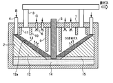
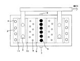
- FIGS. 1A and 1B show a schematic configuration of a molten metal production apparatus according to an embodiment of the present invention.
- the apparatus according to the present embodiment has the same apparatus configuration as the molten metal manufacturing apparatus according to the above-mentioned prior application invention shown in FIGS. 2A and 2B except for a shock generator 18 described later.
- the stationary non-tilting electric furnace electric furnace (hereinafter sometimes simply referred to as “furnace”) according to the present embodiment is an arc furnace having a substantially rectangular horizontal cross section, and the furnace upper part (in this example, the furnace upper part). 1), an exhaust gas duct 3 and a plurality of raw material charging chutes 4 are connected, and a plurality of electrodes 5 are inserted into the furnace via the furnace upper part 1.
- the raw material charging chute 4 is installed at both ends 2 and 2 in the furnace width direction, while the electrode 5 is installed at the center in the furnace width direction.
- a plurality of secondary combustion burners 6 are provided at the furnace upper part (furnace upper part 1 in this example).
- the inside of the furnace above the surface of the molten slag layer 15 and below the surface of the massive metal raw material layer 13, that is, in the massive metal raw material layer 13 or the raw material filling A shock generator 18 is provided in the layer 12 to mechanically eliminate the shelf hanging of the massive metal raw material layer 13.
- the “shock generating device” refers to a device that applies external force to the massive metal raw material layer 13 continuously or intermittently.
- the shock generator 18 is operated directly or intermittently by operating the shock generator 18 continuously or intermittently. Since an external force can be applied indirectly through the raw material packed layer 12, it is possible to prevent shelf hanging from occurring in the bulk metal raw material layer 13, and even if shelf hanging has occurred, molten metal production apparatus The shelf suspension can be eliminated quickly and reliably without stopping the operation.
- the shock generator 18 is installed in the furnace above the surface of the molten slag layer 15 and below the surface of the massive metal raw material layer 13, that is, anywhere in the massive metal raw material layer 13 or the raw material packed layer 12. Although a certain shelf-hanging prevention effect can be obtained, the bulk metal raw material B charged into the furnace from the raw material charging chute 4 has a particle diameter of 90% or less of the average particle diameter of the entire bulk metal raw material B. In the case where 2% by mass or more of the small particles having slag are included, the shock generator 18 is moved from the height position of the lowest end of the raw material charging chute 4 to the lowest end of the raw material charging chute 4 and the surface of the molten slag layer 15 It is recommended that it be provided between the height positions up to 1/3 below the distance.
- the raw material charging chute is introduced when the massive metal raw material B is charged into the furnace from the raw material charging chute 4. Small particles are likely to be deposited in the vicinity of 4 and the small particles are metalized and fixed as soon as they are heated in the furnace, so that shelf hanging is likely to occur near the raw material charging chute 4.
- shock generator 18 at a height just below the raw material charging chute 4, it is possible to effectively prevent shelf hanging caused by the accumulation of small grains without reducing the production yield of the bulk metal raw material B. Will be able to.
- the shock generator 18 includes, for example, a shaft portion 18a having a rotating shaft along the longitudinal direction of the furnace and a plurality of crushing members 18b protruding on the surface thereof (Midrex method direct reduction shaft furnace furnace. It is possible to use a barden feeder that is installed inside and used for preventing shelves of reduced iron from being suspended. And it can prevent that shelf hanging generate
- the shock generator 18 approximated to the above-mentioned Baden feeder has a direction in which the massive metal raw material layer 13 is lowered around its rotational axis (normal). It is only necessary to appropriately select one that rotates only in the direction), or one that rotates alternately in the direction in which the massive metal raw material layer 13 is lowered (forward direction) and the opposite direction.
- the former places importance on transport, and the latter places importance on crushing.
- a shock generator 18 (comprising a shaft portion 18a having a rotation axis along the furnace longitudinal direction and a plurality of crushing members 18b projecting on the surface thereof) similar to the Baden feeder is above the molten slag layer 15.
- the shaft portion 18a is present in the raw material filling layer 12 or the massive metal raw material layer 13, and at least a part of the crushing member 18b is disposed so as to be in contact with the massive metal raw material layer 13. It is recommended that you do this.
- shock generator 18 similar to the Baden feeder has a height from the surface of the molten slag layer 15 to 1/3 above the distance between the surface of the molten slag layer 15 and the lowermost end of the raw material charging chute 4. Recommended between positions.
- partition walls 9, 10, 11 is preferably provided between the electrode 5 and the secondary combustion burner 6, between the secondary combustion burner 6 and the exhaust gas duct 3, and between the exhaust gas duct 3 and the raw material charging chute 4.
- the partition wall 10 be provided between the secondary combustion burner 6 and the exhaust gas duct 3 to prevent the exhaust gas after the secondary combustion from being short-cut to the exhaust gas duct 3, This is to ensure a sufficient amount of radiant heat transfer to 13.
- the partition walls 9, 10, 11 may be installed entirely or a part of them may be installed by comprehensively considering the degree of each effect described above, installation cost, maintenance labor, etc. It may be.
- the exhaust gas duct 3 is preferably installed on the side closer to the raw material charging chute 4 than the electrode 5. This is to prevent the oxidizing exhaust gas after the secondary combustion from flowing toward the electrode 5 and damaging the electrode 5.
- the raw material charging chute 4 is not provided in the lower part of the furnace (that is, the raw material packed layer 12 is not formed in the furnace), and the tap hole 7 and the tap hole 8 Are preferably provided. This is for facilitating the hole opening operation at the time of tapping.
- a known heat exchanger (not shown) may be installed on the downstream side of the exhaust gas duct 3, thereby recovering the sensible heat of the high-temperature exhaust gas discharged from the furnace, and oxygen for the secondary combustion burner It can be used effectively as energy for preheating the contained gas, generating electric power for arc, drying pellet B, and the like.
- the electrode 5 for example, a three-phase AC type that is excellent in thermal efficiency and is commonly used in an arc electric furnace for steelmaking is recommended. And, for example, it is recommended to adopt a configuration in which six electrodes are made from three sets of single-phase electrodes formed by combinations of two phases of three-phase electrodes.
- the electrode 5 is subjected to a melting operation while its tip is positioned (immersed) in the bulk metal raw material layer 13 or the molten slag layer 15.
- the effects of radiant heating and resistance heating by the arc can coexist, melting can be further promoted, and damage to the furnace wall inner surface not protected by the raw material packed bed 12 can be suppressed.
- molten iron is produced as a molten metal using this stationary non-tilting arc furnace
- a carbonaceous material-containing pellet is used as a packed bed forming raw material for forming a raw material packed layer in the furnace
- a carbonaceous material-containing iron oxide pellet is also used as a massive metal raw material laminated on the raw material packed layer.
- a carbonaceous material interior oxidation that is a predetermined amount of a bulk metal raw material as a raw material for forming a packed bed from raw material charging chutes 4 and 4 previously installed at both ends 2 and 2 in the furnace width direction.
- An iron pellet A is charged into the furnace to form a raw material packed layer 12 having a slope 12a having a downward slope extending from both ends 2 and 2 in the furnace width direction toward the lower side of the lower end of the electrode 5 in advance.
- carbonaceous iron-incorporated iron oxide pellets (hereinafter simply referred to as “carbonized iron-incorporated metal oxide agglomerates” from the raw material charging chutes 4 and 4 installed at both ends 2 and 2 in the furnace width direction as a bulk metal raw material.
- pellet. carbonaceous iron-incorporated metal oxide agglomerates
- the blending amount of the interior carbon material in the pellet B may be determined by adding the target C concentration of molten iron to the theoretical C amount necessary for reducing iron oxide to metallic iron.
- the pellet B is preferably dried in advance so as not to burst (bursting) when entering the furnace interior.
- the height of the electrode 5 is preferably adjusted in advance so that the lower end of the electrode 5 is immersed in the pellet layer 13.
- the electrode is energized and subjected to arc heating, whereby the pellet B in the vicinity of the lower end of the pellet layer 13 is rapidly heated and sequentially reduced and melted, and separated into molten iron and molten slag as molten metal,
- the molten iron layer 14 and the molten slag layer 15 are formed in the lower part.
- a CaO source such as limestone or dolomite or an MgO source in advance to the pellet B.
- the pellets B are sequentially melted from the vicinity of the lower end portion of the pellet layer 13.
- the pellet layer 13 itself is caused by its own weight, and further, using the material transfer function of the shock generator 18, the material filling is performed.
- the inside of the furnace is sequentially lowered along the slope of the layer toward the lower end of the electrode 5.
- the pellet B in the pellet layer 13 approaches the electrode 5, it is efficiently heated by the radiant heat and resistance heating by the arc from the electrode 5, and the iron oxide in the pellet B is preliminarily turned into solid metallic iron by the interior carbon material. While being reduced, a CO-containing gas (combustible gas) is generated.
- a carbon material containing volatile components such as coal is used as the interior carbon material, the volatile components devolatilized from the interior carbon material by heating are also added to the CO-containing gas.
- This CO-containing gas is combusted by, for example, oxygen gas (secondary combustion) as an oxygen-containing gas blown from a secondary combustion burner 6 provided in the upper part 1 of the furnace, and is radiated by the combustion (secondary combustion). Also, the pellet layer 13 is heated. In this way, the pellet layer 13 heated by radiant heat is pre-reduced to solid metal iron and the CO-containing gas in the same manner as in the case of radiant heating by the arc from the electrode 5 and resistance heating. Therefore, the radiant heating by the secondary combustion is further promoted.
- oxygen gas secondary combustion
- the pellet layer 13 heated by radiant heat is pre-reduced to solid metal iron and the CO-containing gas in the same manner as in the case of radiant heating by the arc from the electrode 5 and resistance heating. Therefore, the radiant heating by the secondary combustion is further promoted.
- the pellet B charged into the furnace from the raw material charging chute 4 descends on the slope 12a of the raw material packed bed 12 while being radiated by the secondary combustion (hereinafter referred to as “secondary”). It is also referred to as “combustion heat”.) Is preliminarily reduced to a high metalization rate in a solid state, and then melted by arc heating and resistance heating in the vicinity of the lower end portion of the electrode 5 to be separated into molten iron and molten slag.
- the iron oxide concentration in the molten slag generated in the vicinity of the lower end of the electrode 5 becomes sufficiently low, and wear of the electrode 5 can be suppressed.
- the molten iron separated from the molten slag dissolves the carbonaceous material remaining in the pellet B and becomes a molten iron having a target C concentration.
- the molten iron and molten slag generated in this way can be intermittently discharged from the tap hole 7 and the tap hole 8 provided in the lower part of the furnace, for example, in the same manner as in the blast furnace.
- the shock generator 18 is an apparatus of a type that applies an external force to the massive metal raw material layer 13 by rotational movement around the rotation axis, and is similar to a Baden feeder (shaft portion 18a and projecting on the surface thereof)
- the present invention is not limited to this, and any material can be used as long as an external force can be applied continuously or intermittently to the bulk metal raw material layer 13. It can also be used with any type of device.
- a device for example, a screw
- a device for example, a pusher
- a device that applies external force by pressure for example, a device that blows gas directly into the furnace or a device that deforms a diaphragm by gas pressure
- a device that applies external force by pressure for example, a device that blows gas directly into the furnace or a device that deforms a diaphragm by gas pressure
- the electrode 5 is the furnace width direction of the furnace upper part 1
- the electrode 5 may be installed at the other end 2 of the furnace width.
- the example in which the electrode 5 is installed on the center line of the furnace width is shown as an example of installing the electrode 5 on the center part in the furnace width direction.
- the present invention is not limited to this, and it is allowed to be installed by being shifted from the center line of the furnace width toward either end of the furnace width.
- the exhaust gas duct 3 and the raw material charging chute 4 are both connected to the furnace upper part 1.
- the present invention is not limited to this example. You may make it connect to upper part.
- the raw material charging chute 4 is automatically installed at the end of the furnace width.
- the substantially rectangular thing was illustrated as a horizontal cross-sectional shape of a stationary non-tilting type arc furnace, it is not limited to this,
- the thing of a substantially ellipse or a perfect circle is used. May be.
- scale-up can be easily performed by extending the furnace longitudinal direction (direction perpendicular to the furnace width direction) while keeping the furnace width constant.
- the pellet was illustrated as a form of the carbonaceous material interior metal oxide agglomerate B, you may employ
- the briquette has a larger angle of repose than the spherical pellet, so in order to ensure the residence time on the inclined surface 12a of the raw material packed bed 12, it is necessary to increase the furnace height compared to the case of using the pellet, There is an advantage that the furnace width can be reduced.
- Charcoal interior containing metal scrap iron scrap
- reduced metal reduced iron [DRI, HBI]
- bulk metal oxide ore bulk metal oxide ore
- metal chloride instead of pellets and charcoal interior iron oxide briquettes
- Metal chloride agglomerates and metal oxide agglomerates may be used, carbonaceous material interior metal oxide agglomerates, metal scrap, reduced metal
- One or more selected from the group consisting of a massive metal oxide ore, a carbonaceous material-incorporated metal chloride agglomerate, and a metal oxide agglomerated mineral may be used.
- a volatile metal other than a non-volatile metal element was illustrated. It may contain elements such as Zn and Pb. That is, as the carbonaceous material-incorporated metal oxide agglomerate B, steel mill dust containing a volatile metal element can be used as the metal oxide raw material.
- the volatile metal element is heated in the furnace and volatilized and removed from the carbonaceous material-containing metal oxide agglomerate B.
- the temperature of the upper part of the furnace is increased by the combustion heat from the secondary combustion burner 6. Since it can be kept sufficiently high, the volatile metal element that has been volatilized and removed is reliably prevented from re-condensing in the upper part of the furnace, and the volatile metal element is efficiently recovered from the exhaust gas discharged from the furnace. Can do.
- the volatile metal element means a metal element having a melting point of 1100 ° C. or less at 1 atm of a compound such as a simple metal or a salt thereof.
- a compound such as a simple metal or a salt thereof.
- the metal simple substance include zinc and lead.
- the volatile metal element compound include sodium chloride and potassium chloride.
- Volatile metals in the volatile metal element compound are reduced to metals in an electric furnace (for example, an arc furnace, a submerged arc furnace), and a part or all of them are in a gaseous state in the furnace.
- the chloride of the volatile metal element is heated in the electric furnace, and a part or all of the chloride exists in the gaseous state in the furnace.
- the non-volatile metal element means a metal element having a melting point at 1 atm of a metal simple substance or a compound such as an oxide thereof exceeding 1100 ° C.
- the metal simple substance include iron, nickel, cobalt, chromium, titanium and the like.
- the non-volatile metal oxide include CaO, SiO2, and Al2O3.
- iron Fe
- Fe Fe
- the carbonaceous material interior metal oxide agglomerate B as a lump metal raw material
- the molten metal 14, Ni, Mn, Cr other than Fe Nonferrous metals such as may be contained.
- the means which adds a CaO source and a MgO source previously to carbonaceous material interior metal oxide agglomerate B was illustrated as a basicity adjustment means of molten slag, it replaced with or added to this means
- the raw material charging chute 4 may be charged with limestone or dolomite together with the carbonaceous material-incorporated metal oxide agglomerate B, or separately from the carbonaceous material-incorporated metal oxide agglomerate B with a separately provided chute. You may make it enter.
- the carbonaceous material interior iron oxide pellet was illustrated as a filling layer formation raw material which forms the raw material filling layer 12, you may use another lump metal raw material, and use 2 or more types of them together May be.
- a carbon material such as coal or coke may be used instead of or in addition to the bulk metal raw material.
- the particle size of the carbon material-containing iron oxide pellets B is such that the carbon material-containing iron oxide pellets B do not sink into the voids of the raw material packed layer 12 as the raw material packed layer. It is good to adjust according to.
- the tap hole 7 and the tap hole 8 are separately installed on the opposite side walls, but both may be installed on the same side wall side, or It is also possible to omit the dredging hole 8 and install only the dredging hole 7 and discharge the molten iron and molten slag from the dredging hole 7.
Landscapes
- Engineering & Computer Science (AREA)
- Chemical & Material Sciences (AREA)
- Mechanical Engineering (AREA)
- General Engineering & Computer Science (AREA)
- Materials Engineering (AREA)
- Organic Chemistry (AREA)
- Metallurgy (AREA)
- Manufacturing & Machinery (AREA)
- Vertical, Hearth, Or Arc Furnaces (AREA)
- Manufacture And Refinement Of Metals (AREA)
- Manufacture Of Iron (AREA)
- Furnace Charging Or Discharging (AREA)
- Furnace Details (AREA)
Abstract
Description
2…炉幅の端部
3…排ガスダクト
4…原料装入シュート
5…電極
6…二次燃焼バーナ
7…出銑孔
8…出滓孔
9、10、11…隔壁
12…原料充填層
12a…斜面
13…塊状金属原料層(ペレット層)
14…溶融金属層(溶鉄層)
15…溶融スラグ層
16…炉底部
16a…立ち上がり部
17…点検口
18…ショック発生装置
18a…シャフト部
18b…解砕部材
21…軸受け
A…充填層形成用原料(炭材内装酸化鉄ペレット)
B…塊状金属原料(炭材内装酸化金属塊成化物、炭材内装酸化鉄ペレット)
C…酸素含有ガス(酸素)
Claims (7)
- 電気加熱手段を有する定置式非傾動型電気炉の炉上部に排ガスダクトと原料装入シュートとが接続されるとともに、
前記原料装入シュートは炉幅の片端部に設置される一方、前記電気加熱手段は、該電気加熱手段で加熱される電気加熱領域が炉幅の他端部に存在するように設置されるとともに、炉上部に二次燃焼バーナが設置され、
予め、前記原料装入シュートから炭材および/または塊状金属原料を所定量炉内に装入して、前記炉幅の片端部から前記電気加熱領域に向かう下り勾配の斜面を有する原料充填層を形成しておき、
次いで、前記原料装入シュートから塊状金属原料を連続的または間欠的に装入して、前記原料充填層の斜面上に塊状金属原料層を形成し、
その後、前記電気加熱手段にて電気加熱を行って、前記塊状金属原料層の下端部近傍の塊状金属原料を順次溶融することにより、炉内に溶融金属層と溶融スラグ層を形成するとともに、前記塊状金属原料層を前記原料充填層の斜面に沿って降下させつつ、前記二次燃焼バーナから前記塊状金属原料層より上方の炉内空間部に酸素含有ガスを吹き込んで、前記塊状金属原料層から発生するCO含有ガスを燃焼させ、その放射熱により前記塊状金属原料層を加熱し還元することにより溶融金属を製造する溶融金属製造装置であって、
前記溶融スラグ層より上方で、かつ、前記塊状金属原料層の表面より下方の炉内に、該塊状金属原料層の棚吊りを機械的に解消するためのショック発生装置を設けたことを特徴とする溶融金属製造装置。 - 電気加熱手段を有する定置式非傾動型電気炉の炉上部に排ガスダクトと原料装入シュートとを接続するとともに、
原料装入シュートは、炉幅方向の両端部にそれぞれ設置される一方、前記電気加熱手段は、該電気加熱手段で加熱される電気加熱領域が炉幅方向の中央部に存在するように設置されるとともに、炉上部に二次燃焼バーナが設置され、
予め、前記炉幅方向の両端部に設置した原料装入シュートから炭材および/または塊状金属原料を所定量炉内に装入して、該炉幅方向の両端部から前記電気加熱領域に向かう下り勾配の斜面を有する原料充填層を形成しておき、
次いで、前記炉幅方向の両端部に設置した原料装入シュートから塊状金属原料を連続的または間欠的に装入して、前記原料充填層の斜面上に塊状金属原料層を形成し、
その後、前記電気加熱手段にて電気加熱を行って、前記塊状金属原料層の下端部近傍の塊状金属原料を順次溶融することにより、炉内に溶融金属層と溶融スラグ層を形成するとともに、前記塊状金属原料層を前記原料充填層の斜面に沿って降下させつつ、前記二次燃焼バーナから前記塊状金属原料層より上方の炉内空間部に酸素含有ガスを吹き込んで、前記塊状金属原料層から発生するCO含有ガスを燃焼させ、その放射熱により前記塊状金属原料層を加熱することにより溶融金属を製造する溶融金属製造装置であって、
前記溶融スラグ層の表面より上方で、かつ、前記塊状金属原料層の表面より下方の炉内に、該塊状金属原料層の棚吊りを機械的に解消するためのショック発生装置を設けたことを特徴とする溶融金属製造装置。 - 前記原料装入シュートから炉内に装入される塊状金属原料が、該塊状金属原料全体の平均粒径の90%以下の粒径を有する小粒を2質量%以上含む場合には、前記ショック発生装置を、前記原料装入シュートの最下端の高さ位置から、該原料装入シュートの最下端と前記溶融スラグ層の表面との距離の1/3下方までの高さ位置の間に設けた請求項1または2に記載の溶融金属製造装置。
- 前記ショック発生装置が、炉長手方向に沿う回転軸を有するシャフト部と、その表面に突設された解砕部材からなるものである請求項1または2に記載の溶融金属製造装置。
- 前記ショック発生装置は、前記回転軸回りに、前記塊状金属原料層を降下させる方向にのみ回転するもの、または、前記塊状金属原料層を降下させる方向とその逆方向に交互に回転するものである請求項4に記載の溶融金属製造装置。
- 前記シャフト部が前記原料充填層内または前記塊状金属原料層内に存在し、かつ、前記解砕部材の少なくとも一部が前記塊状金属原料層に接触するように、前記ショック発生装置を配置した請求項4に記載の溶融金属製造装置。
- 前記ショック発生装置を、前記溶融スラグ層の表面から、該溶融スラグ層の表面と原料装入シュートの最下端との距離の1/3上方までの高さ位置の間に設けた請求項4に記載の溶融金属製造装置。
Priority Applications (9)
| Application Number | Priority Date | Filing Date | Title |
|---|---|---|---|
| US13/501,068 US9557109B2 (en) | 2009-10-08 | 2010-10-08 | Apparatus for manufacturing molten metal |
| UAA201205618A UA103555C2 (ru) | 2009-10-08 | 2010-10-08 | УСТРОЙСТВО ДЛЯ ПРОИЗВОДСТВА расплавленного металла (ВАРИАНТЫ) |
| KR1020127008859A KR101399806B1 (ko) | 2009-10-08 | 2010-10-08 | 용융 금속 제조 장치 |
| RU2012118646/02A RU2500960C1 (ru) | 2009-10-08 | 2010-10-08 | Устройство для производства расплавленного металла |
| CN201080044543.3A CN102549172B (zh) | 2009-10-08 | 2010-10-08 | 熔融金属制造装置 |
| EP10822143.3A EP2487266A4 (en) | 2009-10-08 | 2010-10-08 | DEVICE FOR PREPARING MELTED METAL |
| AU2010304230A AU2010304230B9 (en) | 2009-10-08 | 2010-10-08 | Apparatus for manufacturing molten metal |
| CA2773241A CA2773241C (en) | 2009-10-08 | 2010-10-08 | Apparatus for manufacturing molten metal |
| NZ598669A NZ598669A (en) | 2009-10-08 | 2010-10-08 | Molten metal production using shock generator to overcome hanging of metal agglomerate |
Applications Claiming Priority (2)
| Application Number | Priority Date | Filing Date | Title |
|---|---|---|---|
| JP2009-234364 | 2009-10-08 | ||
| JP2009234364A JP5330185B2 (ja) | 2009-10-08 | 2009-10-08 | 溶融金属製造装置 |
Publications (1)
| Publication Number | Publication Date |
|---|---|
| WO2011043473A1 true WO2011043473A1 (ja) | 2011-04-14 |
Family
ID=43856922
Family Applications (1)
| Application Number | Title | Priority Date | Filing Date |
|---|---|---|---|
| PCT/JP2010/067792 Ceased WO2011043473A1 (ja) | 2009-10-08 | 2010-10-08 | 溶融金属製造装置 |
Country Status (12)
| Country | Link |
|---|---|
| US (1) | US9557109B2 (ja) |
| EP (1) | EP2487266A4 (ja) |
| JP (1) | JP5330185B2 (ja) |
| KR (1) | KR101399806B1 (ja) |
| CN (1) | CN102549172B (ja) |
| AU (1) | AU2010304230B9 (ja) |
| CA (1) | CA2773241C (ja) |
| NZ (1) | NZ598669A (ja) |
| RU (1) | RU2500960C1 (ja) |
| TW (1) | TW201130988A (ja) |
| UA (1) | UA103555C2 (ja) |
| WO (1) | WO2011043473A1 (ja) |
Families Citing this family (3)
| Publication number | Priority date | Publication date | Assignee | Title |
|---|---|---|---|---|
| US11198174B2 (en) * | 2019-03-28 | 2021-12-14 | Cloverdale Forge | Kit comprising components made from planar sheet material for forming forge table and forge pot, and valve component for selectively communicating airflow source and forge pot |
| AU2021311179B2 (en) * | 2020-07-21 | 2025-01-02 | Sumitomo Metal Mining Co., Ltd. | Method for recovering valuable metal |
| KR102712139B1 (ko) * | 2022-09-29 | 2024-10-02 | 주식회사 영풍 | 응축기를 이용하여 유가금속을 회수하는 방법 |
Citations (7)
| Publication number | Priority date | Publication date | Assignee | Title |
|---|---|---|---|---|
| JPS5178711A (ja) * | 1974-12-30 | 1976-07-08 | Kawasaki Heavy Ind Ltd | Denkiaakushikiseikohoho oyobi sonosochi |
| JPS59134482A (ja) * | 1982-12-22 | 1984-08-02 | ホエスト―アルピン・インダストリーアンラーゲンバウ・ゲゼルシャフト・ミット・ベシュレンクテル・ハフツング | 冶金法 |
| JP2000513411A (ja) | 1996-06-20 | 2000-10-10 | ユーエスエックス エンジニアーズ アンド コンサルタンツ,インコーポレイテッド | ホットメタルの製造方法 |
| JP2001515138A (ja) | 1998-08-28 | 2001-09-18 | 株式会社神戸製鋼所 | 製鉄・製鋼法 |
| JP2001525487A (ja) | 1997-12-03 | 2001-12-11 | シドマール エヌ.ヴイ. | 酸化鉄を還元し鉄を精錬する方法及び装置 |
| JP2003105415A (ja) | 2001-10-01 | 2003-04-09 | Kobe Steel Ltd | 溶融金属の製造方法および装置 |
| JP2009105397A (ja) | 2007-10-19 | 2009-05-14 | Asml Netherlands Bv | リソグラフィ装置および方法 |
Family Cites Families (13)
| Publication number | Priority date | Publication date | Assignee | Title |
|---|---|---|---|---|
| US3907170A (en) * | 1970-08-20 | 1975-09-23 | Ivan Vasilievich Schedrin | Machine for application of powderlike material onto lining or surface of structure |
| EP0118655B1 (de) * | 1982-12-22 | 1988-03-02 | VOEST-ALPINE Aktiengesellschaft | Verfahren zur Durchführung von metallurgischen oder chemischen Prozessen und Niederschachtofen |
| AT380462B (de) * | 1984-08-03 | 1986-05-26 | Sueddeutsche Kalkstickstoff | Verfahren zur herstellung von calciumcarbid sowie schachtofen zur durchfuehrung des verfahrens |
| JPS6462438A (en) * | 1987-08-31 | 1989-03-08 | Hyuga Smelting | Electric furnace smelting method for nickel-containing ore |
| JPH05178711A (ja) * | 1991-12-27 | 1993-07-20 | Sumitomo Chem Co Ltd | テンサイの増糖剤 |
| US6149709A (en) | 1997-09-01 | 2000-11-21 | Kabushiki Kaisha Kobe Seiko Sho | Method of making iron and steel |
| DE19744151C5 (de) * | 1997-10-07 | 2004-08-26 | Outokumpu Oyj | Verfahren zum Schmelzen von feinkörnigem, direkt reduziertem Eisen in einem Elektrolichtbogenofen |
| JP3919338B2 (ja) * | 1998-06-23 | 2007-05-23 | 株式会社広築 | 粉体付着防止装置を備えたロータリーキルン |
| US6614831B2 (en) * | 2000-02-10 | 2003-09-02 | Process Technology International, Inc. | Mounting arrangement for auxiliary burner or lance |
| KR20020006207A (ko) * | 2000-07-11 | 2002-01-19 | 이구택 | 석회소성로 내에서 발생하는 탈착광 파쇄제어장치 |
| DE102006052181A1 (de) | 2006-11-02 | 2008-05-08 | Sms Demag Ag | Verfahren zur kontinuierlichen oder diskontinuierlichen Gewinnung eines Metalls oder mehrerer Metalle aus einer das Metall oder eine Verbindung des Metalls enthaltenden Schlacke |
| CN1973987A (zh) * | 2006-11-10 | 2007-06-06 | 泸天化(集团)有限责任公司 | 一种防止或者消除流化床内壁结壁的装置 |
| US8425650B2 (en) | 2008-04-23 | 2013-04-23 | Kobe Steel, Ltd. | Method for manufacturing molten metal |
-
2009
- 2009-10-08 JP JP2009234364A patent/JP5330185B2/ja not_active Expired - Fee Related
-
2010
- 2010-10-08 US US13/501,068 patent/US9557109B2/en not_active Expired - Fee Related
- 2010-10-08 TW TW099134400A patent/TW201130988A/zh unknown
- 2010-10-08 CA CA2773241A patent/CA2773241C/en active Active
- 2010-10-08 RU RU2012118646/02A patent/RU2500960C1/ru not_active IP Right Cessation
- 2010-10-08 NZ NZ598669A patent/NZ598669A/xx not_active IP Right Cessation
- 2010-10-08 AU AU2010304230A patent/AU2010304230B9/en not_active Ceased
- 2010-10-08 WO PCT/JP2010/067792 patent/WO2011043473A1/ja not_active Ceased
- 2010-10-08 UA UAA201205618A patent/UA103555C2/ru unknown
- 2010-10-08 EP EP10822143.3A patent/EP2487266A4/en not_active Withdrawn
- 2010-10-08 KR KR1020127008859A patent/KR101399806B1/ko not_active Expired - Fee Related
- 2010-10-08 CN CN201080044543.3A patent/CN102549172B/zh not_active Expired - Fee Related
Patent Citations (7)
| Publication number | Priority date | Publication date | Assignee | Title |
|---|---|---|---|---|
| JPS5178711A (ja) * | 1974-12-30 | 1976-07-08 | Kawasaki Heavy Ind Ltd | Denkiaakushikiseikohoho oyobi sonosochi |
| JPS59134482A (ja) * | 1982-12-22 | 1984-08-02 | ホエスト―アルピン・インダストリーアンラーゲンバウ・ゲゼルシャフト・ミット・ベシュレンクテル・ハフツング | 冶金法 |
| JP2000513411A (ja) | 1996-06-20 | 2000-10-10 | ユーエスエックス エンジニアーズ アンド コンサルタンツ,インコーポレイテッド | ホットメタルの製造方法 |
| JP2001525487A (ja) | 1997-12-03 | 2001-12-11 | シドマール エヌ.ヴイ. | 酸化鉄を還元し鉄を精錬する方法及び装置 |
| JP2001515138A (ja) | 1998-08-28 | 2001-09-18 | 株式会社神戸製鋼所 | 製鉄・製鋼法 |
| JP2003105415A (ja) | 2001-10-01 | 2003-04-09 | Kobe Steel Ltd | 溶融金属の製造方法および装置 |
| JP2009105397A (ja) | 2007-10-19 | 2009-05-14 | Asml Netherlands Bv | リソグラフィ装置および方法 |
Non-Patent Citations (1)
| Title |
|---|
| See also references of EP2487266A4 * |
Also Published As
| Publication number | Publication date |
|---|---|
| KR101399806B1 (ko) | 2014-05-27 |
| AU2010304230A1 (en) | 2012-04-05 |
| CN102549172A (zh) | 2012-07-04 |
| CA2773241A1 (en) | 2011-04-14 |
| AU2010304230B9 (en) | 2013-10-24 |
| US9557109B2 (en) | 2017-01-31 |
| JP5330185B2 (ja) | 2013-10-30 |
| EP2487266A4 (en) | 2015-08-26 |
| TW201130988A (en) | 2011-09-16 |
| RU2012118646A (ru) | 2013-11-20 |
| KR20120056291A (ko) | 2012-06-01 |
| EP2487266A1 (en) | 2012-08-15 |
| CN102549172B (zh) | 2014-01-29 |
| RU2500960C1 (ru) | 2013-12-10 |
| NZ598669A (en) | 2013-05-31 |
| JP2011080714A (ja) | 2011-04-21 |
| UA103555C2 (ru) | 2013-10-25 |
| CA2773241C (en) | 2014-02-18 |
| US20120200013A1 (en) | 2012-08-09 |
| AU2010304230B2 (en) | 2013-06-13 |
Similar Documents
| Publication | Publication Date | Title |
|---|---|---|
| CN102575305B (zh) | 熔融金属制造装置 | |
| JP5563783B2 (ja) | 溶融金属の製造方法 | |
| JP5330185B2 (ja) | 溶融金属製造装置 | |
| JP5368243B2 (ja) | 溶融金属製造装置 | |
| JP5400553B2 (ja) | 溶融金属製造装置 | |
| JP5426988B2 (ja) | 溶融金属製造装置 |
Legal Events
| Date | Code | Title | Description |
|---|---|---|---|
| WWE | Wipo information: entry into national phase |
Ref document number: 201080044543.3 Country of ref document: CN |
|
| 121 | Ep: the epo has been informed by wipo that ep was designated in this application |
Ref document number: 10822143 Country of ref document: EP Kind code of ref document: A1 |
|
| WWE | Wipo information: entry into national phase |
Ref document number: 2773241 Country of ref document: CA |
|
| WWE | Wipo information: entry into national phase |
Ref document number: 2010304230 Country of ref document: AU |
|
| WWE | Wipo information: entry into national phase |
Ref document number: 2010822143 Country of ref document: EP |
|
| WWE | Wipo information: entry into national phase |
Ref document number: 3081/CHENP/2012 Country of ref document: IN |
|
| ENP | Entry into the national phase |
Ref document number: 2010304230 Country of ref document: AU Date of ref document: 20101008 Kind code of ref document: A Ref document number: 20127008859 Country of ref document: KR Kind code of ref document: A |
|
| WWE | Wipo information: entry into national phase |
Ref document number: 13501068 Country of ref document: US |
|
| NENP | Non-entry into the national phase |
Ref country code: DE |
|
| WWE | Wipo information: entry into national phase |
Ref document number: A201205618 Country of ref document: UA |
|
| WWE | Wipo information: entry into national phase |
Ref document number: 2012118646 Country of ref document: RU |