WO2011045835A1 - 触覚センサシステム - Google Patents
触覚センサシステム Download PDFInfo
- Publication number
- WO2011045835A1 WO2011045835A1 PCT/JP2009/005358 JP2009005358W WO2011045835A1 WO 2011045835 A1 WO2011045835 A1 WO 2011045835A1 JP 2009005358 W JP2009005358 W JP 2009005358W WO 2011045835 A1 WO2011045835 A1 WO 2011045835A1
- Authority
- WO
- WIPO (PCT)
- Prior art keywords
- tactile sensor
- sensor
- bus
- signal
- sensor system
- Prior art date
- Legal status (The legal status is an assumption and is not a legal conclusion. Google has not performed a legal analysis and makes no representation as to the accuracy of the status listed.)
- Ceased
Links
Images


Classifications
-
- H—ELECTRICITY
- H04—ELECTRIC COMMUNICATION TECHNIQUE
- H04L—TRANSMISSION OF DIGITAL INFORMATION, e.g. TELEGRAPHIC COMMUNICATION
- H04L12/00—Data switching networks
- H04L12/28—Data switching networks characterised by path configuration, e.g. LAN [Local Area Networks] or WAN [Wide Area Networks]
- H04L12/40—Bus networks
- H04L12/40006—Architecture of a communication node
- H04L12/40032—Details regarding a bus interface enhancer
-
- G—PHYSICS
- G01—MEASURING; TESTING
- G01L—MEASURING FORCE, STRESS, TORQUE, WORK, MECHANICAL POWER, MECHANICAL EFFICIENCY, OR FLUID PRESSURE
- G01L1/00—Measuring force or stress, in general
- G01L1/14—Measuring force or stress, in general by measuring variations in capacitance or inductance of electrical elements, e.g. by measuring variations of frequency of electrical oscillators
- G01L1/142—Measuring force or stress, in general by measuring variations in capacitance or inductance of electrical elements, e.g. by measuring variations of frequency of electrical oscillators using capacitors
- G01L1/146—Measuring force or stress, in general by measuring variations in capacitance or inductance of electrical elements, e.g. by measuring variations of frequency of electrical oscillators using capacitors for measuring force distributions, e.g. using force arrays
-
- G—PHYSICS
- G01—MEASURING; TESTING
- G01L—MEASURING FORCE, STRESS, TORQUE, WORK, MECHANICAL POWER, MECHANICAL EFFICIENCY, OR FLUID PRESSURE
- G01L5/00—Apparatus for, or methods of, measuring force, work, mechanical power, or torque, specially adapted for specific purposes
- G01L5/22—Apparatus for, or methods of, measuring force, work, mechanical power, or torque, specially adapted for specific purposes for measuring the force applied to control members, e.g. control members of vehicles, triggers
- G01L5/226—Apparatus for, or methods of, measuring force, work, mechanical power, or torque, specially adapted for specific purposes for measuring the force applied to control members, e.g. control members of vehicles, triggers to manipulators, e.g. the force due to gripping
- G01L5/228—Apparatus for, or methods of, measuring force, work, mechanical power, or torque, specially adapted for specific purposes for measuring the force applied to control members, e.g. control members of vehicles, triggers to manipulators, e.g. the force due to gripping using tactile array force sensors
-
- G—PHYSICS
- G06—COMPUTING OR CALCULATING; COUNTING
- G06F—ELECTRIC DIGITAL DATA PROCESSING
- G06F13/00—Interconnection of, or transfer of information or other signals between, memories, input/output devices or central processing units
- G06F13/14—Handling requests for interconnection or transfer
- G06F13/36—Handling requests for interconnection or transfer for access to common bus or bus system
- G06F13/368—Handling requests for interconnection or transfer for access to common bus or bus system with decentralised access control
- G06F13/376—Handling requests for interconnection or transfer for access to common bus or bus system with decentralised access control using a contention resolving method, e.g. collision detection, collision avoidance
-
- H—ELECTRICITY
- H04—ELECTRIC COMMUNICATION TECHNIQUE
- H04L—TRANSMISSION OF DIGITAL INFORMATION, e.g. TELEGRAPHIC COMMUNICATION
- H04L12/00—Data switching networks
- H04L12/28—Data switching networks characterised by path configuration, e.g. LAN [Local Area Networks] or WAN [Wide Area Networks]
- H04L12/40—Bus networks
- H04L12/40006—Architecture of a communication node
- H04L12/40013—Details regarding a bus controller
Definitions
- the present invention relates to a tactile sensor system that is provided, for example, on a surface portion (for example, a hand portion or the entire body surface) of a robot and detects contact with an object.
- the conventional tactile sensor system mainly adopts a mesh structure. For example, a plurality of electrode wirings are formed on each of two electrode sheets. And mesh-like wiring is formed by arrange
- the control unit is connected to each electrode wiring and centrally manages a plurality of tactile sensor elements. That is, the control unit sequentially selects each tactile sensor element and samples the sensor value of each sensor. In the control unit, electrical signals from the tactile sensor elements are integrated and processed. By periodically repeating such a sampling operation, it is detected whether the robot is in contact with the object and which sensor is in contact. Thereby, it is possible to sense at what position the robot is in contact with the object at what level.
- the conventional tactile sensor system has the following problems.
- the control unit manages a large number of tactile sensor elements in a centralized manner, selects each tactile sensor element in order, and samples the sensor value of each sensor, so the sampling interval increases as the number of sensors increases. Becomes longer. Then, the response speed becomes low, and it is inevitable that the reaction becomes dull.
- control unit samples all the tactile sensor elements in order
- the sensor data is acquired also from the tactile sensor to which no force is applied. Then, the amount of data to be processed by the control unit becomes enormous, increasing the processing load on the control unit and increasing the processing time. In addition, a large amount of power is required to process a huge amount of data.
- Patent Documents 1 to 6 have the following problems. Patent Documents 1 and 2 provide sufficient sensitivity for a mesh-type wiring-type tactile sensor system, but there are still further problems in increasing the data amount and the host load.
- Patent Document 3 selects a tactile sensor that is a sensing target around a tactile sensor element in which pressurization is detected with respect to a plurality of sheet-like tactile sensors. According to this, the data amount and the calculation amount can be reduced to some extent.
- the host controller must centrally manage a large number of sensors, and the host controller must handle the determination of pressure and the exchange of data requests. This reduces data volume and host load. Still have issues.
- Patent Document 4 discloses that by using a flexible substrate for wiring and providing a foldable region and a severable region, adjustment of the arrangement density of the tactile sensor elements and adjustment of the mounting region can be easily performed. However, when the number of sensor elements increases, there remains a problem that the data amount and the host load increase.
- Patent Documents 5 and 6 disclose that a transfer bottleneck can be avoided in the configuration of an interconnection type contact sensor system, and the burden of information processing on the host side can be reduced. That is, when the output value of the tactile sensor can be predicted from the output value of the adjacent sensor, the sensor data is not transmitted to the host. However, since it is an interconnection type, it is necessary to construct a path of sensor information sequentially. In addition, depending on the sensor value of the tactile sensor, it is necessary to continue outputting data, and thus there is a possibility that reduction of the data amount and the host processing load may not be realized.
- An object of the present invention is to provide a tactile sensor system capable of high-speed response without increasing the amount of data and increasing the host processing load while having a large number of tactile sensor elements.
- the tactile sensor system of the present invention includes: One or more buses, A plurality of tactile sensor devices arranged for each bus; and An information integration device that is connected to all the buses and integrates information from the plurality of tactile sensor devices;
- the tactile sensor device includes: A sensor unit that outputs an analog sensor signal that changes according to the action from the detection target; A signal processing unit that transmits a sensor data signal obtained by signal processing of an analog sensor signal from the sensor unit to the information integration device via the bus, and The signal processing unit A digital converter for digitally converting the analog sensor signal; A threshold determination unit that gives permission to start signal processing when the sensor value by the sensor unit exceeds a preset threshold; An ID adding unit for adding a sender identification number assigned to the sensor data signal in advance, A data transmission unit that outputs the sensor data signal to a signal line of a bus.
- the tactile sensor device has a sensor unit and a signal processing unit, and the signal processing unit processes the analog sensor signal.
- the signal processing unit processes the analog sensor signal.
- the tactile sensor device includes a digital conversion unit, and digitally converts an analog sensor signal. Therefore, since a digital signal is transmitted from the touch sensor device to the information integration device, even if the wiring length between the touch sensor device and the information integration device is long, it is less susceptible to noise. For example, if the tactile sensor device is provided on the entire body surface of the robot, the entire wiring length becomes considerably long, so noise resistance becomes important. Compared to the case where the analog signal is transmitted as it is, the configuration of the present invention is suitable for a sensor system including a large number of tactile sensor devices.
- the tactile sensor device includes a threshold value determination unit, and transmits sensor data to the information integration device only when the sensor value exceeds a predetermined threshold value. Therefore, the amount of data flowing through the bus as a whole is reduced, and the bus crosstalk is reduced. Since the bus is not mixed, the transmission waiting time is reduced, and the sensed data is transmitted from each tactile sensor device to the information integration device at a desired timing, and the sensing response is accelerated.
- the tactile sensor device includes an ID adding unit, and transmits a sensor data signal with its own sender identification number. With this sender identification number, the information integration device can identify the transmission source tactile sensor device. Therefore, it becomes unnecessary to exchange request packets between the information integration device and the tactile sensor device, and the tactile sensor device can immediately transmit sensor data when a detection exceeding the threshold is detected.
- the bus may be mixed by itself.
- the tactile sensor device can be disposed anywhere on the bus, the arrangement of the tactile sensor device can be freely changed. For example, while a large number of tactile sensor devices are densely arranged in the hand portion, the number of tactile sensor devices can be reduced in the back portion. In addition, since a plurality of tactile sensor devices can be arranged on the bus one by one, the number of wirings can be drastically reduced as compared with the case of wiring to each tactile sensor device.
- the whole block diagram of a tactile sensor system The figure which shows a mode that the tactile sensor system was applied to the robot hand. The figure which shows a mode that the some tactile sensor apparatus is arrange
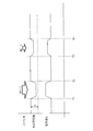
- the functional block diagram of a tactile sensor apparatus Sectional drawing which shows an example of the structure of a tactile sensor apparatus. The figure which shows a mode that the distance d between electrode plates and the electric charge Q between electrode plates change according to the applied force. The figure for demonstrating the procedure which digitally converts an electrostatic capacitance change into a frequency change. The figure which shows the structural example of transmission data.
- the flowchart which shows the operation procedure of initial setting in a tactile sensor apparatus. The flowchart which shows the operation
- FIG. 1 is an overall configuration diagram of the tactile sensor system 100.
- FIG. 2 is a diagram illustrating a state in which the tactile sensor system 100 is applied to a robot hand.
- FIG. 3 is a diagram illustrating a state in which a plurality of tactile sensor devices 200 are arranged on the bus 110.
- the tactile sensor system 100 includes a plurality of buses 110, a plurality of tactile sensor devices 200, an information relay device 120, a line concentrator 130, and an information integration device 140.
- the bus 110 is wired to the flexible substrate 111 as shown in FIG.
- Each bus 110 is provided with a plurality of tactile sensor devices 200.
- An information relay device 120 is provided in the middle of each bus 110, and a plurality of buses 110 are once connected to the concentrator 130. All buses 110 are connected to the information integration device 140 via the information relay device 120 and the concentrator 130.
- the phase delay of the communication speed is within ⁇ (radian) at each point on the bus.
- the wiring structure of the bus 110 is not limited to the example shown in FIG. 1, but can be freely changed, as well as a single string, tree, branch, fish bone, net, ring, star, and plane Various wiring structures such as a lattice shape can be taken.
- FIG. 4 is a functional block diagram of the tactile sensor device.
- FIG. 5 is a cross-sectional view showing an example of the structure of the tactile sensor device 200.
- the tactile sensor device 200 includes a sensor unit 210 and a signal processing unit 300.
- the sensor unit 210 and the signal processing unit 300 are bonded together, and the tactile sensor device 200 is made into one chip.
- the diaphragm-type force sensor unit 210 and the LSI on which the signal processing unit 300 is integrated are bonded together by the adhesive layer 220, and the whole is integrated into one package.
- the sensor unit 210 includes two electrode plates 211 and 211 arranged to face each other. Further, the upper surface of the sensor unit 210 is a sensor surface 212 that comes into contact with the object, and when the sensor surface 212 is pressed, the distance between the two electrode plates 211 and 211 changes. The change in capacitance due to the change in the electrode plate interval becomes an analog sensor signal.
- the analog sensor signal is output to the signal processing unit 300 and subjected to signal processing.
- a block diagram of the signal processing unit 300 is shown in FIG.
- the signal processing unit 300 includes a clock control unit 310, a digital conversion unit 320, a threshold determination unit 330, a data generation unit 340, a serialization unit 350, a bus state determination unit 360, a data transmission unit 370, an initial A transmission command unit 380.
- the clock control unit 310 generates a clock and supplies an operation clock to each functional unit 310-380 after performing predetermined frequency division.
- the digital conversion unit 320 digitally converts the analog signal from the sensor unit 210. The manner of digitally converting the capacitance change into the frequency change will be described with reference to FIG.
- the digital conversion unit 320 extracts the sensor signal from the sensor unit 210, the digital conversion unit 320 outputs the selection signal Sct and the reset signal Rst at a constant cycle.
- the selection signal Sct is an ON signal of a switch (not shown) disposed between the electrode plate 211 and the signal processing unit 300.
- the reset signal Rst is a signal for resetting the charge of the electrode plate once to GND.
- the inter-electrode charge amount Q is taken out at a constant period.
- the inter-electrode charge amount Q thus taken out is converted into a voltage V Q via a predetermined resistance. Contrasting this V Q with a predetermined reference voltage Vref. Then, it generates a pulse signal Vout having a time width V Q exceeds the Vref. At this time, if the withdrawal rate of the charge is constant, the pulse width of the high and Vout of V Q has a positive correlation.
- Vout is converted into a pulse signal having a predetermined frequency by a pulse generator (not shown). By counting the number of pulses per unit time, the force applied to the sensor unit 210 can be measured as a digital quantity. The sensor signal digitized by frequency conversion in this manner is used as a digital sensor signal.
- a predetermined sensor threshold is set.
- the threshold determination unit 330 compares the digital sensor signal with the sensor threshold. If the digital sensor signal does not exceed the sensor threshold, the sensor signal processing is stopped. On the other hand, when the digital sensor signal exceeds the sensor threshold, the data generation unit 340 is caused to continue the process for outputting the sensor signal to the outside.
- the data generation unit 340 generates transmission data to be transmitted to the information integration device 140 when the threshold determination unit 330 determines that the digital sensor signal has exceeded the sensor threshold.
- each tactile sensor device 200 is set with a different sender identification number ID.
- the sender identification numbers ID are set to be different from each other without overlapping between touch sensor devices arranged on the same bus 110.
- the tactile sensor device 200 disposed at the end of the bus 110 is given a termination number indicating the termination as a sender identification number ID.
- An example of the termination number is a maximum value that can be set as the sender identification signal. For example, when the sender identification number ID is set in the range of 0 to 255, the termination number is 255.
- the data generation unit 340 includes an ID adding unit 341 that adds a sender identification number ID to the digital sensor signal.
- the ID adding unit 341 adds its own sender identification number ID to the digital sensor signal.
- the data generation unit 340 generates transmission data by adding a preamble, a start bit, a CRC bit (Cyclic Redundancy Check), and a stop bit (see FIG. 8).
- the data generation unit 340 encodes transmission data according to the transmission method (for example, 4B5B encoding).
- the serialization unit 350 serializes the transmission data generated by the data generation unit 340 for serial transmission.
- the bus state determination unit 360 determines the state of the signal line 113 of the bus 110 at a constant cycle. Specifically, the bus state determination unit 360 determines whether the signal line 113 of the bus 110 is busy or free. Then, the determination result is output to the data transmission unit 370. That is, when the bus 110 is busy, a transmission standby instruction is output. If the bus 110 is free, a transmission permission is output.
- the bus state determination unit 360 determines the state of the bus 110 again after a preset waiting time has elapsed. Further, the bus state determination unit 360 increases the waiting time by a predetermined ratio when the bus 110 is continuously determined to be busy.
- the data transmission unit 370 transmits the transmission data generated by the data generation unit 340 on the signal line 113 of the bus 110.
- the data transmission unit 370 confirms an instruction from the bus state determination unit 360 before data transmission. That is, when there is a transmission standby instruction, the data transmission unit 370 waits without transmitting data.
- the transmission data is transmitted on the signal line 113 of the bus 110.
- the data transmission unit 370 has a counter (not shown), and counts the time waiting for data transmission. When the transmission data holding time to be transmitted exceeds the predetermined time (maximum holding time) without transmission permission, the sensor data signal is discarded.
- the counter starts counting after transmitting data once, and stops data transmission during the transmission interval time so as to leave a preset transmission interval before the next transmission.
- the data transmission unit 370 transmits data by a differential serial transmission method when transmitting data.
- the data transmission unit 370 transmits data in an asynchronous manner using the clock generated by the clock control unit 310 as a reference. That is, without exchanging request packets with the information integration device 140, the data transmission unit 370 starts data transmission at its own timing after the transmission permission is obtained.
- the clock of each signal processing unit is used, not the clock of the information integration device. Because of such a configuration, a dedicated bus line for the clock is not necessary. Since a clock used for communication is generated for each sensor unit, a preamble for start-stop synchronization is provided at the head of the data. In order to facilitate start-stop synchronization, synchronization information is generated in the 4b5b encoding unit, and NRZI (Non Return to Zero, Inverted) is used. The information integration device synchronizes signals with the transmission side by CDR (Clock Data Recovery).
- CDR Lock Data Recovery
- the information integration device and the tactile sensor device Bus control is not performed. That is, handshaking represented by ACK and NAK is not performed. Therefore, a cyclic redundancy code (code for error detection) represented by CRC is used in order to improve data reliability.
- CRC code for error detection
- the data received by the information integration device is analyzed, and if an error due to CRC is detected, the data is discarded.
- NAK is sent and data is requested to be sent again.
- the communication form is one-way from the sensor unit to the information integration device, data is sent. Only discard data without requesting retransmission. Thereby, the stability of the control system can be efficiently maintained.
- the initial transmission command unit 380 commands the data generation unit 340 to transmit the sender identification number ID when the power is turned on.
- Each tactile sensor device 200 has a different sender identification number ID, and the initial transmission command unit 380 waits for a waiting time corresponding to the sender identification number ID after detecting power-on, The data generation unit 340 is instructed to transmit the sender identification number ID.
- the time required for one tactile sensor device 200 to perform transmission of the sender identification number ID as the initial transmission is Ts, and the sender identification number ID is set between 0 and 255. .
- the waiting time corresponding to the sender identification number ID is set to (ID value) ⁇ Ts. If the standby time of each tactile sensor device 200 is set in this way, the transmission timings are shifted, so that the bus 110 is not congested and smooth initial setting is possible.
- the information relay device 120 is provided in the middle of the bus 110, relays data of the tactile sensor device 200 provided on the bus 110, and transmits the data to the information integration device 140.
- Each information relay device 120 is set with a different sender identification number ID, and further adds its own sender identification number ID to the data from the tactile sensor device 200.
- the line concentrator 130 is connected to the plurality of buses 110 and collects the plurality of buses 110. Different concentrator IDs are set in the concentrator 130, and the own transmitter ID number ID is further added to the data from the tactile sensor device 200.
- the sender identification numbers of a plurality of tactile sensor devices provided on one bus 110 must be different from each other. However, if the bus 110 is different, the same sender is assigned to different tactile sensor devices 200. An identification number may be given. That is, since the sender identification number ID of the information relay device 120 and the concentrator 130 is added while data is transmitted via the information relay device 120 and the concentrator 130, the same transmitter identification number ID is attached. However, it is recognized as a different tactile sensor device 200 from the information integration device 140.
- the information integration device 140 receives transmission data from each tactile sensor device 200 and integrates all information. Information integration by the information integration device 140 detects where and how much force is applied to the tactile sensor system 100.
- the information integration device 140 performs initial setting after power is turned on.
- each transmitter identification number ID transmitted from each tactile sensor device 200 after power-on is received, and a communication network of the sensor system is constructed. That is, the sender identification numbers ID of all tactile sensor devices 200 connected to the system are grasped, and how the tactile sensor device 200 is connected to the bus 110 via the line concentrator 130 and the information relay device 120. Know what you are doing.
- a network structure may be constructed using position information of each tactile sensor device 200 set and input from the outside.
- FIG. 9 is a flowchart showing an initial setting operation procedure in each tactile sensor device 200.
- the initial transmission command unit 380 detects this.
- the initial transmission command unit 380 detects power-on (ST110: YES)
- the initial transmission command unit 380 waits for a time corresponding to the sender identification number ID given to its own tactile sensor device 200 (ST111).
- the data generation unit 340 When the standby time ends (ST112: YES), the data generation unit 340 is instructed to generate transmission data. Data generation section 340 adds the preamble, start bit, CRC bit (Cyclic Redundancy Check), and stop bit to the sender identification number ID given to itself, and generates transmission data (ST113). The generated transmission data is sent to the data transmission unit 370.
- CRC bit Cyclic Redundancy Check
- the data transmission unit 370 confirms the determination result by the bus state determination unit 360 before data transmission (S114).
- each tactile sensor device 200 waits for a waiting time corresponding to the sender identification number ID given to itself, so it is considered that the bus 110 is rarely congested.
- the data transmission unit 370 transmits the transmission data on the signal line 113 of the bus 110 (ST116). If the bus 110 is busy (ST115: NO), the state of the bus 110 is determined again after waiting for a predetermined time (ST114).
- Initial transmissions from all tactile sensor devices 200 are received by the information integration device 140.
- the information integration device 140 grasps the sender identification number ID of all the tactile sensor devices 200 connected to the system, and further, the tactile sensor device 200 is connected via the concentrator 130 and the information relay device 120. Understand how the bus 110 is connected. In this way, the initial setting is completed.
- the information integration device 140 resets the system by turning on the power again and executes the initial setting operation again.
- the tactile sensor device 200 After the power is turned on and the initial setting transmission is completed, the tactile sensor device 200 performs a sensing operation (ST210).
- the sensing operation means that the capacitance change between the electrode plates is converted into a frequency change and a physical quantity (for example, force) applied to the sensor surface 212 is taken out as a digital sensor signal.
- this sensing operation is always executed by the digital conversion unit 320 using a selection signal Sct having a fixed period.
- the digital sensor signal is sent to the threshold determination unit 330 and compared with a preset sensor threshold.
- the digital sensor signal does not exceed the sensor threshold value (ST211: NO)
- the digital sensor signal transmission processing is not performed and the processing returns to the sensing operation again.
- transmission data generation ST212 for outputting the digital sensor signal to the outside is performed.
- Transmission data generation is performed in data generation section 340. That is, a transmitter identification number ID is added to the digital sensor signal, and a preamble, a start bit, a CRC bit (Cyclic Redundancy Check), and a stop bit are added to generate transmission data (see FIG. 8).
- the transmission data generated in this way is serialized by the serialization unit 350 (ST213) and output to the data transmission unit 370.
- Data transmission section 370 determines whether a plurality of conditions (ST214, ST215, ST216) are satisfied before transmitting data. That is, first, the determination result of the bus state by the bus state determination unit 360 is confirmed. When the bus 110 is busy, a transmission standby instruction is issued from the bus state determination unit 360 to the data transmission unit. Then, the bus state determination unit 360 determines the state of the bus 110 again after a preset waiting time has elapsed.
- the data transmission unit 370 checks whether a transmission interval is available. That is, it confirms whether the time from the previous data transmission is equal to or longer than the transmission interval time, and waits until the transmission interval time elapses. When the transmission interval time has elapsed (ST215: YES), it is next checked whether the data retention time is within the maximum retention time. When the data holding time is within the maximum holding time (ST216), the data transmission unit 370 transmits the transmission data on the signal line 113 of the bus 110. The transmitted data is sent to the information integration device 140 via the information relay device 120 and the concentrator 130.
- the data transmitting unit 370 discards the data without transmitting the data, returns to ST210, and executes from sensing.
- the information integration device 140 sequentially receives transmission data from the tactile sensor device 200. Then, the information integration device 140 detects where and how much force is applied to the tactile sensor system 100 based on the received data. Here, if there is a tactile sensor device 200 that does not transmit data for a certain period of time despite being registered in the communication network constructed in the initial setting, it is determined that the tactile sensor device has failed and the communication Delete from the net.
- FIG. 11 is a diagram in which the power consumption of one tactile sensor device 200 is plotted with the horizontal axis as the time axis. After turning on the power, the tactile sensor device 200 performs initial transmission after waiting for a time corresponding to its own sender identification number ID. The power consumption peak at the initial transmission appears.
- the threshold determination unit 330 determines that the digital sensor signal does not exceed the sensor threshold, and subsequent data processing is not performed. Therefore, up to 40 ⁇ s, only the power necessary for sensing (digital conversion) is consumed.
- a strong force exceeding the threshold is applied after 40 ⁇ s. Then, transmission data is generated by the data generation unit 340, and the data is transmitted. Since the power of the transmission process is large, a power consumption peak appears during the transmission operation. Furthermore, since a strong force continues to be applied, the tactile sensor device 200 tries to continue to generate transmission data. However, since force is applied to all the tactile sensor devices 200, the bus 110 becomes busy and a waiting time occurs. The bus state determination unit 360 increases the waiting time at a predetermined ratio when the bus 110 is continuously determined to be busy, indicating that the transmission interval becomes longer.
- the tactile sensor device 200 includes a sensor unit 210 and a signal processing unit 300, and the signal processing unit 300 performs signal processing on an analog sensor signal.
- the signal processing load of the information integration device 140 can be reduced. Even if a large number of tactile sensor devices 200 are arranged in the sensor system, the increase in processing load of the information integration device 140 can be reduced, so that a high-speed response is possible even with a large system having a large number of tactile sensor devices 200.
- the tactile sensor system can be a periodical.
- the tactile sensor device 200 includes a digital conversion unit 320, and digitally converts an analog sensor signal. Therefore, since a digital signal is transmitted from the touch sensor device 200 to the information integration device 140, even if the wiring length between the touch sensor device 200 and the information integration device 140 is long, it is less susceptible to noise. For example, if the tactile sensor device 200 is provided on the entire body surface of the robot, the entire wiring length becomes considerably long, so noise resistance becomes important. Compared to the case where the analog signal is transmitted as it is, the configuration of the present embodiment is suitable for a sensor system including a large number of tactile sensor devices 200.
- the tactile sensor device 200 includes an ID adding unit 341 and transmits a sensor data signal with its own sender identification number. With this sender identification number, the information integration device 140 can identify the touch-sensitive sensor device 200 as the transmission source. Accordingly, exchange of request packets between the information integration device 140 and the tactile sensor device 200 becomes unnecessary, and the tactile sensor device 200 can immediately transmit sensor data when a detection exceeding the threshold is detected. If a request packet is exchanged with a large number of tactile sensor devices 200, the bus 110 may be mixed only by that. In this regard, in this embodiment, it is possible to construct a sensor system capable of reducing the amount of data flowing through the bus 110 and capable of high-speed response even when a large number of tactile sensor devices 200 are provided.
- the tactile sensor device 200 can be arranged anywhere on the bus 110, the arrangement of the tactile sensor device 200 can be freely changed. For example, a large number of tactile sensor devices 200 can be densely arranged in the hand portion, while the number of tactile sensor devices 200 can be reduced in the back portion. Further, since a plurality of tactile sensor devices 200 can be arranged on the bus 110 one by one, the number of wirings can be drastically reduced as compared with the case of wiring to each tactile sensor device.
- the tactile sensor device 200 includes a bus state determination unit 360, and transmits data from the data transmission unit 370 when the bus 110 is free.
- a bus state determination unit 360 When many tactile sensor devices 200 are provided in one bus 110, there is a high possibility that the bus 110 is congested. Conventionally, the host performs centralized management such as issuing a request packet in order to control the bus. However, there is a problem that the bus is occupied for exchanging request packets. In this regard, in this embodiment, when each tactile sensor device 200 can determine and transmit the state of the bus 110, the sensor data signal is transmitted. Therefore, even if a large number of tactile sensor devices 200 are provided in one bus 110, congestion of the bus 110 is avoided, and a sensor system having a quick response can be obtained.
- the data transmission unit 340 discards the held sensor data signal and acquires the latest data Run from. If a large number of tactile sensor devices 200 are provided, the transmission standby time may be long. In such a case, sending unnecessary sensor data delayed in time will lead to a bus battle and increase the processing load on the information integration device 140.
- the latest sensor data is acquired when the holding time has passed for a predetermined time or longer, so that sensor data delayed in time is not sent wastefully.
- the data transmission unit 370 stops data transmission for a preset waiting time until the next transmission. Therefore, it is possible to prevent the bus 110 from being occupied by continuous transmission from one or a few tactile sensor devices 200, and the information integration device 140 can obtain detection data of the entire system. Further, since the waiting time is set according to the sender identification number, the waiting time is different for each tactile sensor device 200. Therefore, for example, even when a plurality of tactile sensor devices 200 are waiting for transmission at the same time, the waiting times are different. As a result, each tactile sensor device 200 transmits data at a timing shifted from each other, so that congestion of the bus 110 is avoided as much as possible.
- the waiting time is different for each tactile sensor device, so that the waiting time may be set regardless of the sender identification number.
- a start-stop synchronization method is adopted for data transmission between the tactile sensor device 200 and the information integration device 140.
- the host processing load is large even if the transmission timing is managed and controlled on the host side.
- a low voltage differential signal interface called LVDS (Low Voltage Differential Signaling) is used.
- LVDS Low Voltage Differential Signaling
- the bus is occupied by the request packet.
- an asynchronous process is employed, and data is transmitted from the touch sensor device 200 to the information integration device 140 at an arbitrary timing of the touch sensor device 200. Therefore, even if a large number of tactile sensor devices 200 are provided, the processing load on the information integration device 140 is reduced, and the response speed of the sensor system can be increased.
- the number of signal lines 113 and 113 is very small, two.
- the noise resistance is sufficiently high. Therefore, this embodiment is suitable for a sensor system including a large number of tactile sensor devices 200.
- the tactile sensor device 200 transmits the sender identification number when detecting that the power is turned on. That is, the information integration device 140 can recognize and distinguish the tactile sensor device 200 provided in the system by recording the sender identification number transmitted first. According to such a configuration, the arrangement position of the tactile sensor device 200 does not have to be fixed. For example, when the arrangement configuration of the tactile sensor device 200 is changed, if the power is turned on again, the information integration device 140 automatically receives the sender identification number from each tactile sensor device 200 and establishes a communication network. Can be built.
- the initial transmission command unit waits for a time corresponding to the sender identification number after detecting power-on, and then commands transmission of the sender identification signal.
- the tactile sensor devices 200 perform data transmission at different timings, so congestion of the bus 110 is avoided as much as possible.
- the information integration device 140 Since the termination number is set for the tactile sensor device 200 provided at the termination of each bus 110, the information integration device 140 receives this termination number at the initial transmission stage, so that You can recognize the end. As a result, the information integration device 140 can identify each end of the bus 110 and construct a communication network. In addition, by using the maximum value (for example, 255) that can be set as the sender identification signal as the termination number, it is not necessary to set a termination number separately, thereby simplifying the system and reducing information to be processed. Can do.
- the maximum value for example, 255
- the present invention is not limited to the above-described embodiment, and can be changed as appropriate without departing from the spirit of the present invention.
- the case where the force applied to the sensor unit is detected from the change in the distance between the two electrode plates is exemplified.
- the configuration of the sensor unit any physical quantity that can be detected can be detected. It is not particularly limited.
- the configuration of the tactile sensor device is that the sensor unit is MEMS (Micro Electro Mechanical Systems), the components are integrated on the substrate, and the signal processing unit is also integrated on the semiconductor substrate.
- MEMS of the sensor unit and the semiconductor substrate of the signal processing unit Are preferably combined into a single integrated sensor element chip.
- the tactile sensor device does not necessarily have to be integrated.
- the sensor unit and the signal processing unit may be separate from each other and arranged close to each other.
- the sensor sensitivity and the sensor threshold value may be set as follows.
- setting the sensor sensitivity means adjusting and setting the voltage level and the sampling clock in the digital conversion unit.
- a memory and a register are incorporated in the tactile sensor device.
- the sensor sensitivity and the sensor threshold value are set in the memory.
- a mask ROM, an OTP (One Time Programmable) memory, an EPROM (Erasabele Programmable ROM), or the like can be adopted as the memory.
- the timing for setting the sensor sensitivity and the sensor threshold value in the memory may be at the time of manufacturing the tactile sensor device, before the sensor system is mounted on the robot, or after the sensor system is mounted on the robot.
- the data is written into the memory using a dedicated write terminal.
- the tactile sensor device may be set by individual learning, or the ID and setting information are transmitted from the information integration device Then, each sensor device may take in the setting information with the ID corresponding to itself and set it in the memory. In this way, the sensor sensitivity and the sensor threshold are set in the memory, and during operation, the register takes in the sensor sensitivity and the sensor threshold from the memory. Then, the digital conversion unit adjusts the voltage level and the sampling clock based on the sensor sensitivity set in the register.
- the threshold determination unit performs threshold determination using the sensor threshold set in the register.
- the sensor sensitivity and the sensor threshold of the sensor device can be set flexibly according to the position where the robot is attached. Since the sensor sensitivity and the sensor threshold can be set, the balance between the quality and amount of transmission data can be adjusted appropriately, and as a result, the load on the information integration apparatus can be reduced.
- the frequency of data collision can be reduced, a high-speed response is possible, and more than several hundred tactile sensor devices can be installed.
- the present invention can be used, for example, in a tactile sensor system that is provided on a surface portion (for example, a hand portion or the entire body surface) of a robot and detects contact with an object.
- a tactile sensor system that is provided on a surface portion (for example, a hand portion or the entire body surface) of a robot and detects contact with an object.
Landscapes
- Engineering & Computer Science (AREA)
- General Physics & Mathematics (AREA)
- Physics & Mathematics (AREA)
- Power Engineering (AREA)
- Theoretical Computer Science (AREA)
- Computer Networks & Wireless Communication (AREA)
- Signal Processing (AREA)
- Chemical & Material Sciences (AREA)
- Analytical Chemistry (AREA)
- General Engineering & Computer Science (AREA)
- Arrangements For Transmission Of Measured Signals (AREA)
- Force Measurement Appropriate To Specific Purposes (AREA)
- Manipulator (AREA)
Abstract
Description
制御部がホストとなって集中的に多数の触覚センサ素子を管理し、順番に各触覚センサ素子を選択して各センサのセンサ値をサンプリングしていくので、センサ数の増加に伴ってサンプリング間隔が長くなる。
すると、応答速度が低速になってしまい、反応が鈍くなることが避けられない。
また、膨大なデータを処理するためには多量の電力を必要とする。
特許文献1、2は、メッシュ状配線方式の触覚センサシステムに十分な感度を提供するものであるが、データ量増大およびホスト負荷増大になお一層の問題がある。
これによればデータ量、計算量はある程度低減できる。
しかしながら、センサ素子数が増えた場合、データ量やホスト負荷が増大する問題が残る。
しかし、相互接続型であるので、センサ情報の経路を逐次構築する必要がある。
また、触覚センサのセンサ値によってはデータを出力し続ける必要があるため、データ量やホスト処理負担の低減が実現されないおそれがある。
一本以上のバスと、
バスごとに複数個ずつ配置された複数の触覚センサ装置と、
総てのバスと接続され、前記複数の触覚センサ装置からの情報を統合する情報統合装置と、を備え、
前記触覚センサ装置は、
検出対象物からの作用に応じて変化するアナログセンサ信号を出力するセンサ部と、
前記センサ部からのアナログセンサ信号を信号処理したセンサデータ信号を前記バスを介して前記情報統合装置に送信する信号処理部と、を有し、
前記信号処理部は、
前記アナログセンサ信号をデジタル変換するデジタル変換部と、
センサ部によるセンサ値が予め設定された閾値を超えた場合に信号処理の開始許可を出す閾値判定部と、
予め自己に付された送信者識別番号を前記センサデータ信号に付加するID付加部と、
前記センサデータ信号をバスの信号ラインに出力するデータ送信部と、を備える
ことを特徴とする。
したがって、触覚センサ装置から情報統合装置へはデジタル信号を送信するので、触覚センサ装置と情報統合装置との配線長が長くてもノイズの影響を受けにくくなる。
例えばロボットの体表面全体に触覚センサ装置を設けるとすると全体の配線長はかなりの長さになるのでノイズ耐性が重要になる。
アナログ信号のままで送信する場合に比べて、本発明の構成は多数の触覚センサ装置を備えるセンサシステムに好適である。
したがって、全体としてバスを流れるデータ量が少なくなり、バスの混線が少なくなる。
バスが混線しなくなるので、送信待ち時間が少なくなり、センシングされたデータが望ましいタイミングで各触覚センサ装置から情報統合装置に送信されるようになり、センシングの応答が速くなる。
触覚センサ装置の数が多くなった場合であってもバスの混線が少なく、応答の速いセンサシステムとすることができる。
この送信者識別番号によって情報統合装置は送信元の触覚センサ装置を特定することができる。
したがって、情報統合装置と触覚センサ装置との間リクエストパケットのやり取りが不要になり、触覚センサ装置は閾値を超える検出があった場合にすぐにセンサデータを送信することができる。
この点、本発明では、バスを流れるデータ量を少なくし、多数の触覚センサ装置が設けられていても高速応答が可能なセンサシステムを構築することができる。
たとえば、ハンド部には密に多数の触覚センサ装置を配置する一方、背中部分では触覚センサ装置の数を少なくすることをもできる。
また、一つにバスに複数の触覚センサ装置を配置することができるので、一つ一つの触覚センサ装置に配線する場合に比べて配線数を劇的に削減することができる。
(第1実施形態)
本発明の触覚センサシステム100に係る第1実施形態について説明する。
図1は、触覚センサシステム100の全体構成図である。
図2は、触覚センサシステム100をロボットハンドに適用した様子を示す図である。
図3は、バス110に複数の触覚センサ装置200が配置された様子を示す図である。
バス110の配線ラインとしては4本のライン112、112、113、113が設けられている。
4本のうち2本は電源ライン112、112であり、2本は差動シリアル伝送用の信号ライン113、113である。
各バス110の途中には情報中継装置120が設けられ、さらに、複数のバス110が一旦集線装置130に接続されている。
そして、情報中継装置120および集線装置130を介して総てのバス110は情報統合装置140に接続されている。
このとき、バス上の各点において、通信速度の位相遅れがπ(ラジアン)以内であることが好ましい。
これにより、バス状態判定部の動作が安定に行われ、複数のセンサ部からの信号がバス上で衝突することが回避される。
図5は、触覚センサ装置200の構造の一例を示す断面図である。
触覚センサ装置200は、センサ部210と、信号処理部300と、を備えている。
ここで、センサ部210と信号処理部300とは貼り合わされ、触覚センサ装置200はワンチップ化されている。
この例では、ダイヤフラム型の力覚センサ部210と、信号処理部300を集積したLSIと、が接着層220によって貼り合わされ、全体が一体的なワンパッケージとなっている。
また、センサ部210の上面が対象物と接触するセンサ面212となっており、センサ面212が押されると、2枚の電極板211、211の間隔が変化する。電極板間隔の変化による静電容量変化がアナログセンサ信号となる。
すると、印加された力に応じて極板間距離dが変化する。
極板間距離dの変化に応じて、極板間に蓄積される電荷量Qが変化する。
印加される力に応じて変化する極板間電荷量Qをアナログセンサ信号として取り出す。
信号処理部300のブロック図を図4に示す。
信号処理部300は、クロック制御部310と、デジタル変換部320と、閾値判定部330と、データ生成部340と、シリアル化部350と、バス状態判定部360と、データ送信部370と、初期送信指令部380と、を備える。
静電容量変化を周波数変化にデジタル変換する様子を図7を用いて説明する。
デジタル変換部320は、センサ部210からのセンサ信号を取り出すにあたって、選択信号Sctと、リセット信号Rstと、を一定周期で出す。
選択信号Sctは、電極板211と信号処理部300との間に配置されたスイッチ(不図示)のON信号である。
リセット信号Rstは、極板の電荷を一旦GNDにしてリセットするための信号である。
このように取り出された極板間電荷量Qを所定の抵抗を介して電圧VQに変換する。
このVQを所定の参照電圧Vrefと対比する。そして、VQがVrefを超えている時間幅を有するパルス信号Voutを生成する。このとき、電荷の取り出し速度が一定であれば、VQの高さとVoutのパルス幅は正の相関を持つ。
パルスジェネレータ(不図示)によってVoutを所定周波数のパルス信号に変換する。
単位時間あたりのパルス数をカウントすることにより、センサ部210にかかる力をデジタル量として計測することができる。
このように周波数変換によってデジタル化されたセンサ信号をデジタルセンサ信号とする。
閾値判定部330は、デジタルセンサ信号を前記センサ閾値と対比する。
デジタルセンサ信号がセンサ閾値を超えない場合には、センサ信号の処理を停止する。
一方、デジタルセンサ信号がセンサ閾値を超えた場合、センサ信号を外部出力するための処理をデータ生成部340に続行させる。
ここで、各触覚センサ装置200にはそれぞれ異なる送信者識別番号IDが設定されている。
送信者識別番号IDは、同じバス110に配設されている触覚センサ装置同士では重複することなく互いに異なるように設定されている。
終端番号としては、送信者識別信号として設定可能な最大値とすることが例として挙げられる。
例えば、0-255の範囲で送信者識別番号IDを設定する場合、終端番号は255である。
閾値判定部330からセンサ閾値を超えたデジタルセンサ信号が与えられると、ID付加部341は、このデジタルセンサ信号に対して自己の送信者識別番号IDを付加する。
また、データ生成部340は、送信データを伝送方式に応じて符号化する(例えば4B5B符号化)。
具体的には、バス状態判定部360は、バス110の信号ライン113がビジーかフリーかを判定する。そして、判定結果をデータ送信部370に出力する。すなわち、バス110がビジーである場合には、送信待機指示を出力する。
また、バス110がフリーであった場合には、送信許可を出力する。
また、バス状態判定部360は、バス110が連続してビジー判定であった場合、前記待ち時間を所定の比率で増加させる。
ここで、データ送信部370は、データ送信の前にバス状態判定部360からの指示を確認する。
すなわち、送信待機指示がある場合には、データ送信部370は、データ送信をせずに待機する。
また、バス状態判定部360から送信許可がある場合には、送信データをバス110の信号ライン113にのせて送信する。
そして、送信許可が無い状態で送信すべき送信データの保持時間が所定時間(最大保持時間)を超過した場合、センサデータ信号を破棄する。
なお、データ送信部370は、クロック制御部310にて生成されたクロックを基準に用いて、調歩同期式でデータを送信する。
すなわち、情報統合装置140との間でリクエストパケットのやり取りなどを行うことなく、データ送信部370は送信許可が得られた後、自分のタイミングでデータ送信を開始する。
このような構成であるので、クロック専用のバスラインは不要である。
通信に使われるクロックがセンサ部ごとにつくられるので、調歩同期のためのプリアンブルがデータの先頭に設けられている。
また、調歩同期を容易とするために、4b5b符号化部で同期用情報の生成を行い、さらにNRZI(Non Return to Zero, Inverted)を用いている。
情報統合装置はCDR(Clock Data Recovery)によって送信側と信号の同期をとる。
本方式では、バス本数の低減、通信の簡略化による信号処理部の小規模化、通信量の低減による輻輳の回避、および、通信速度の向上を行うために、情報統合装置や触覚センサ装置によるバス制御を行っていない。
すなわち、ACKやNAKに代表されるハンドシェイクを実施しない。
そこで、データの信頼性を高めるためにCRCで代表される巡回冗長符号(誤り検出のための符号)を用いる。
情報統合装置で受け取ったデータを解析し、CRCによる誤りが検知された場合はそのデータを破棄する。
一般的な通信では、通信誤りが検知されたときはNAKを送り、再度データを送ることを要求するが、本実施形態では、センサ部から情報統合装置への一方向の通信形態をとるのでデータ再送の要求はせずに、データ破棄のみとする。
これにより、制御系の安定を効率よく維持することができる。
各触覚センサ装置200にはそれぞれ異なる送信者識別番号IDが設定されているところ、初期送信指令部380は電源投入を検知してから送信者識別番号IDに応じた待機時間だけ待機したのちに、データ生成部340に送信者識別番号IDの送信を指令する。
このように各触覚センサ装置200の待機時間を設定すれば、送信タイミングがそれぞれずれるので、バス110が輻輳しなくなり、円滑な初期設定が可能になる。
各情報中継装置120にはそれぞれ異なる送信者識別番号IDが設定されており、触覚センサ装置200からのデータにさらに自己の送信者識別番号IDを付加する。
集線装置130は、複数のバス110に接続され、これら複数のバス110を集線している。
集線装置130にはそれぞれ異なる送信者識別番号IDが設定されており、触覚センサ装置200からのデータにさらに自己の送信者識別番号IDを付加する。
すなわち、情報中継装置120、集線装置130を介してデータが伝送される間に情報中継装置120および集線装置130の送信者識別番号IDが付加されていくので、同じ送信者識別番号IDが付されていても情報統合装置140からは異なる触覚センサ装置200として認識される。
情報統合装置140による情報統合により、触覚センサシステム100のどこにどの程度の力が印加されているかが検出される。
初期設定では、電源投入後に各触覚センサ装置200から送信されてくるそれぞれの送信者識別番号IDを受信して、センサシステムの通信網を構築する。
すなわち、システムに繋がっている総ての触覚センサ装置200の送信者識別番号IDを把握し、さらに、集線装置130、情報中継装置120を介して、触覚センサ装置200がどのようにバス110に繋がっているかを把握する。
または、外部から設定入力される各触覚センサ装置200の位置情報を用いてネットワーク構造を構築してもよい。
図9は、各触覚センサ装置200において、初期設定の動作手順を示すフローチャートである。
電源が投入されると、初期送信指令部380がこれを検知する。
初期送信指令部380が電源投入を検知すると(ST110:YES)、初期送信指令部380は、自己の触覚センサ装置200に与えられた送信者識別番号IDに応じた時間だけ待機する(ST111)。
データ生成部340は、自己に与えられた送信者識別番号IDに、プリアンブル、スタートビット、CRCビット(Cyclic Redundancy Check)、ストップビットを付加して、送信データを生成する(ST113)。
生成された送信データはデータ送信部370に送られる。
初期送信にあたっては、各触覚センサ装置200がそれぞれ自己に与えられた送信者識別番号IDに応じた待機時間だけ待機するので、バス110が輻輳すること場合は少ないと考えられる。
バス110の状態がフリーである場合(ST115:YES)、データ送信部370はバス110の信号ライン113に送信データをのせて送信する(ST116)。
なお、バス110がビジーであった場合には(ST115:NO)、所定時間待って再度バス110の状態を判定する(ST114)。
これにより、情報統合装置140は、システムに繋がっている総ての触覚センサ装置200の送信者識別番号IDを把握し、さらに、集線装置130、情報中継装置120を介して、触覚センサ装置200がどのようにバス110に繋がっているかを把握する。
このようにして初期設定が完了する。
電源投入されて、初期設定送信が終了したのち、触覚センサ装置200はセンシング動作を行う(ST210)。
ここでいうセンシング動作とは、極板間の静電容量変化を周波数変化にデジタル変換し、センサ面212にかかった物理量(例えば力)をデジタルセンサ信号として取り出すことをいう。
このセンシング動作は、図7で説明したように、デジタル変換部320において一定周期の選択信号Sct等によって常時実行される。
デジタルセンサ信号がセンサ閾値を超えない場合には(ST211:NO)、このデジタルセンサ信号の送信処理は行わず、再びセンシング動作に戻る。
一方、デジタルセンサ信号がセンサ閾値を超えていた場合(ST211:YES)、このデジタルセンサ信号を外部出力するための送信データ生成(ST212)を行う。
すなわち、デジタルセンサ信号に送信者識別番号IDを付加するとともに、プリアンブル、スタートビット、CRCビット(Cyclic Redundancy Check)、ストップビットを付加して、送信データを生成する(図8参照)。
このように生成された送信データは、シリアル化部350にてシリアル化され(ST213)、データ送信部370に出力される。
バス110がビジーである場合、バス状態判定部360からデータ送信部に送信待機指示が出される。そして、バス状態判定部360は、予め設定された待ち時間経過後に再度バス110の状態を判定する。
すなわち、前回のデータ送信からの時間が送信間隔時間以上になっているかを確認し、送信間隔時間が経過するまで待機する。
送信間隔時間が経過したところで(ST215:YES)、次にデータの保持時間が最大保持時間以内であるか否かを確認する。
データの保持時間が最大保持時間以内である場合(ST216)、データ送信部370は送信データをバス110の信号ライン113にのせて送信する。
送信されたデータは情報中継装置120、集線装置130を介して情報統合装置140に送られる。
ここで、初期設定で構築した通信網に登録されているにも関わらず、一定時間以上データを送信してこない触覚センサ装置200があった場合、その触覚センサ装置は故障したと判断し、通信網から削除する。
次に、図11を参照して、実際の動作例を示す。
触覚センサシステム100に電源投入をした後、40μsまでは総ての触覚センサ装置200に閾値未満の弱い力を印加し、40μs経過後に総ての触覚センサ装置200に閾値以上の力を印加した。
図11は、横軸を時間軸として、一つの触覚センサ装置200の消費電力をプロットした図である。
電源投入後、触覚センサ装置200は、自己の送信者識別番号IDに応じた時間だけ待機したのちに初期送信を行う。
この初期送信時の消費電力ピークが現れている。
この場合、デジタルセンサ信号がセンサ閾値を超えないことを閾値判定部330が判定し、以後のデータ処理が行われない。
したがって、40μsまではセンシング(デジタル変換)に必要な電力分だけが消費される。
すると、送信データがデータ生成部340によって生成されてデータが送信される。
送信処理の電力が大きいので、送信動作時に消費電力ピークが現れる。
さらに、強い力が印加され続けているので、触覚センサ装置200は送信データを生成し続けようとする。
しかしながら、総ての触覚センサ装置200に力が印加されているのでバス110がビジーになり、待機時間が発生する。そして、バス状態判定部360は、バス110が連続してビジー判定であった場合、待ち時間を所定の比率で増加させるので、送信間隔が長くなっていくことが示されている。
(1)触覚センサ装置200は、センサ部210と信号処理部300とを有しており、信号処理部300にてアナログセンサ信号を信号処理する。
このように個々の触覚センサ装置200にて信号処理を実行するので、情報統合装置140の信号処理負荷を少なくすることができる。
センサシステムに多数の触覚センサ装置200を配置したとしても情報統合装置140の処理負担の増加を小さくできるので、多数の触覚センサ装置200を有する大きなシステムでありながらも高速応答が可能になるという画期的な触覚センサシステムとすることができる。
したがって、触覚センサ装置200から情報統合装置140へはデジタル信号を送信するので、触覚センサ装置200と情報統合装置140との配線長が長くてもノイズの影響を受けにくくなる。
例えばロボットの体表面全体に触覚センサ装置200を設けるとすると全体の配線長はかなりの長さになるのでノイズ耐性が重要になる。
アナログ信号のままで送信する場合に比べて、本実施形態の構成は多数の触覚センサ装置200を備えるセンサシステムに好適である。
したがって、全体としてバス110を流れるデータ量が少なくなり、バス110の混線が少なくなる。
バス110が混線しなくなるので、送信待ち時間が少なくなり、センシングされたデータが望ましいタイミングで各触覚センサ装置200から情報統合装置140に送信されるようになり、センシングの応答が速くなる。
また、検出が何も無い場合や閾値以下の検出ではデータの送受信を行わないので、情報統合装置140が処理するデータ量が少なくなり、情報統合装置140の処理負荷が軽くなる。
触覚センサ装置200の数が多くなった場合であってもバス110の混線が少なく、応答の速いセンサシステムとすることができる。
この送信者識別番号によって情報統合装置140は送信元の触覚センサ装置200を特定することができる。
したがって、情報統合装置140と触覚センサ装置200との間リクエストパケットのやり取りが不要になり、触覚センサ装置200は閾値を超える検出があった場合にすぐにセンサデータを送信することができる。
多数の触覚センサ装置200との間でリクエストパケットのやり取りが発生するとそれだけでバス110が混線してしまう恐れもある。
この点、本実施形態では、バス110を流れるデータ量を少なくし、多数の触覚センサ装置200が設けられていても高速応答が可能なセンサシステムを構築することができる。
たとえば、ハンド部には密に多数の触覚センサ装置200を配置する一方、背中部分では触覚センサ装置200の数を少なくすることをもできる。
また、一つにバス110に複数の触覚センサ装置200を配置することができるので、一つ一つの触覚センサ装置に配線する場合に比べて配線数を劇的に削減することができる。
一つのバス110に多数の触覚センサ装置200が設けられていると、バス110が輻輳してしまう恐れが高い。
従来はバスを制御するためにホストがリクエストパケットを発行するなどの集中管理を行っていたが、リクエストパケットのやり取りにバスが占有されてしまうという問題がある。
この点、本実施形態では、各触覚センサ装置200がバス110の状態を判断して送信可能である場合にセンサデータ信号を送信する。
したがって、一つのバス110に多数の触覚センサ装置200が設けられてもバス110の輻輳が回避され、応答の速いセンサシステムとすることができる。
多数の触覚センサ装置200が設けられていると、送信待機時間が長くなる場合もあり得る。
このような場合に時機に遅れた無駄なセンサデータを送信することは、バスの混戦を招くとともに情報統合装置140の処理負担も増加させてしまう。
この点、本実施形態によれば、保持時間が所定時間以上経過した場合には最新のセンサデータを取得するので、時機に遅れたセンサデータを無駄に送ることがなくなる。
したがって、ひとつまたは少数の触覚センサ装置200からの連続送信でバス110が占有されてしまうことを防止することができ、情報統合装置140はシステム全体の検出データを得ることができる。
また、前記待ち時間を送信者識別番号に応じて設定しているので、触覚センサ装置200ごとに待ち時間が異なるようになる。
したがって、たとえば、複数の触覚センサ装置200が同時に送信待ちになったとしても待機時間がそれぞれ異なる。
これにより、各触覚センサ装置200がそれぞれずれたタイミングでデータ送信を行うようになるので、バス110の輻輳が極力回避される。
多数の触覚センサ装置200が設けられていると、それらの送信タイミングをホスト側で管理制御するだけでもホストの処理負担が大きい。
差動シリアル伝送に際して、LVDS(Low Voltage Differential Signaling)と呼ばれる低電圧差動信号インターフェースを用いる。
また、リクエストパケットによってバスが占有される問題もある。
この点、本実施形態では、調歩同期式を採用し、触覚センサ装置200から情報統合装置140には触覚センサ装置200の任意のタイミングでデータが送信される。
したがって、多数の触覚センサ装置200が設けられていても情報統合装置140の処理負担が軽くなるとともに、センサシステムの応答速度を高速にすることができる。
例えばロボットの体表面全体に触覚センサ装置200を配設することを考えると、バス110の配線数が非常に多くなることになる。
このとき、バス110の信号ラインが多いとバス110の幅がそれだけ広くなり、ロボット体表面全体に配線する場合には望ましくない。
また、触覚センサ装置200とバス110との配線接続をする手間も信号ラインの数の増加に比例して多くなるので、多数の触覚センサ装置200を配設することを考えると信号ラインは少ない方が望ましい。
この点、本実施形態では、信号ライン113、113は二本と非常に少なくする。
また、二本の信号ラインで差動信号を送信するので、ノイズ耐性も十分に高い。
したがって、本実施形態は、多数の触覚センサ装置200を備えるセンサシステムに好適である。
すなわち、情報統合装置140は、最初に送信されてくる送信者識別番号を記録しておくことで、システムに配備されている触覚センサ装置200を認識しかつ区別することができる。
このような構成によれば、触覚センサ装置200の配設位置は固定的でなくてもよくなる。
たとえば、触覚センサ装置200の配置構成を変更した場合には、電源の再投入を行えば、自動的に情報統合装置140が各触覚センサ装置200からの送信者識別番号を受信して通信網を構築することができる。
このような構成によれば、各触覚センサ装置200がそれぞれずれたタイミングでデータ送信を行うようになるので、バス110の輻輳が極力回避される。
また、終端番号として送信者識別信号として設定可能な最大値(例えば255)を利用することにより、別途に終端番号を設定する必要がなくなり、システムの簡素化および処理すべき情報の削減を図ることができる。
上記実施形態においては、センサ部にかかった力を二枚の電極板の距離の変化から検出する場合を例示したが、センサ部の構成としては、検出対象となる物理量を検出できるものであれば特に限定されるものではない。
ただし、触覚センサ装置は必ずしも集積化されていなくてもよく、たとえばセンサ部と信号処理部とがそれぞれ別体であって、互いに近接して配置されていてもよい。
ここで、センサ感度の設定とは、デジタル変換部における電圧レベルやサンプリングクロックを調整して設定することをいう。
触覚センサ装置にメモリとレジスタを組み込む。
そして、メモリにセンサ感度、センサ閾値を設定する。
ここで、メモリとしては、マスクROM、OTP(One Time Programmable)メモリ、EPROM(Erasabele Programmable ROM)などが採用できる。
メモリにセンサ感度、センサ閾値を設定するタイミングは、触覚センサ装置の製造時またはセンサシステムをロボットに実装する前でもよく、あるいは、センサシステムをロボットに実装した後でもよい。
触覚センサ装置の製造時またはセンサシステムをロボットに実装する前にメモリにセンサ感度、センサ閾値を設定する場合には、専用の書き込み端子を用いてメモリに書き込む。
センサシステムをロボットに実装した後でメモリにセンサ感度、センサ閾値を書き込む場合には、触覚センサ装置が個別学習で設定するようにしてもよく、または、情報統合装置からIDと設定情報とを送信し、自身に該当するIDが付された設定情報を各センサ装置が取り込んでメモリに設定するようにしてもよい。
このような方法でメモリにセンサ感度、センサ閾値を設定しておき、動作時にはレジスタがメモリからセンサ感度、センサ閾値を取り込む。
そして、デジタル変換部は、レジスタに設定されたセンサ感度に基づいて電圧レベルやサンプリングクロックを調整する。
また、閾値判定部は、レジスタに設定されたセンサ閾値を用いて閾値判定を行う。
このような構成によれば、ロボットに取り付けられる位置に応じてセンサ装置のセンサ感度、センサ閾値が柔軟に設定可能となる。
センサ感度、センサ閾値が設定できることにより、送信データの質と量とのバランスを適切に調整でき、結果として情報統合装置の負荷を軽減することができる。
また、センサ感度、センサ閾値が適切に設定されることでデータ衝突の頻度を下げることができ、高速な応答が可能になるとともに数百を超える触覚センサ装置を設置することが可能になる。
Claims (22)
- 一本以上のバスと、
バスごとに複数個ずつ配置された複数の触覚センサ装置と、
総てのバスと接続され、前記複数の触覚センサ装置からの情報を統合する情報統合装置と、を備え、
前記触覚センサ装置は、
検出対象物からの作用に応じて変化するアナログセンサ信号を出力するセンサ部と、
前記センサ部からのアナログセンサ信号を信号処理したセンサデータ信号を前記バスを介して前記情報統合装置に送信する信号処理部と、を有し、
前記信号処理部は、
前記アナログセンサ信号をデジタル変換するデジタル変換部と、
センサ部によるセンサ値が予め設定された閾値を超えた場合に信号処理の開始許可を出す閾値判定部と、
予め自己に付された送信者識別番号を前記センサデータ信号に付加するID付加部と、
前記センサデータ信号をバスの信号ラインに出力するデータ送信部と、を備える
ことを特徴とする触覚センサシステム。 - 請求項1に記載の触覚センサシステムにおいて、
前記信号処理部は、バスの信号ラインの状態を判定するバス状態判定部を備え、
前記バス状態判定部は、バスがビジーである場合、前記データ送信部の信号送信を停止させ、
バスがフリーである場合、前記データ送信部の信号送信を許可する
ことを特徴とする触覚センサシステム。 - 請求項2に記載の触覚センサシステムにおいて、
前記バス状態判定部は、バスがビジーであった場合、予め設定された待ち時間経過後に再度バスの状態を判定する
ことを特徴とする触覚センサシステム。 - 請求項3に記載の触覚センサシステムにおいて、
前記バス状態判定部は、前記待ち時間が連続して発生した場合には、待機時間を所定の比率で増加させる
ことを特徴とする触覚センサシステム。 - 請求項2から請求項4のいずれかに記載の触覚センサシステムにおいて、
前記データ送信部は、送信許可が無い状態で送信すべきセンサデータ信号の保持時間が所定時間を超過した場合、前記センサデータ信号を破棄する
ことを特徴とする触覚センサシステム。 - 請求項1から請求項5のいずれかに記載の触覚センサシステムにおいて、
前記データ送信部は、
前記センサデータ信号を一度送信した後、次の送信までに予め設定された待ち時間だけデータ送信を停止する
ことを特徴とする触覚センサシステム。 - 請求項6に記載の触覚センサシステムにおいて、
前記待ち時間は、前記送信者識別番号に応じて決定される
ことを特徴とする触覚センサシステム。 - 請求項1から請求項7のいずれかに記載の触覚センサシステムにおいて、
前記データ送信部は、調歩同期方式によって前記センサデータ信号を送信する
ことを特徴とする触覚センサシステム。 - 請求項1から請求項8のいずれかに記載の触覚センサシステムにおいて、
前記信号処理部は、センサデータ信号をシリアル化するシリアル変換部を備え、
前記データ送信部は、前記シリアル変換部にてシリアル変換されたデータを送信する
ことを特徴とする触覚センサシステム。 - 請求項9に記載の触覚センサシステムにおいて、
前記バスの信号ラインは二本であって、
前記データ送信部は、差動シリアル伝送によって前記センサデータ信号を伝送する
ことを特徴とする触覚センサシステム。 - 請求項1から請求項10のいずれかに記載の触覚センサシステムにおいて、
前記信号処理部は、
電源が投入されたことを検知した場合に、前記送信者識別番号の送信を指令する初期送信指令部を備える
ことを特徴とする触覚センサシステム。 - 請求項11に記載の触覚センサシステムにおいて、
前記初期送信指令部は、電源の投入を検知してから前記送信者識別番号に応じた時間だけ待機したのち、前記送信者識別信号の送信を指令する
ことを特徴とする触覚センサシステム。 - 請求項11または請求項12に記載の触覚センサシステムにおいて、
各バスの終端に設けられた触覚センサ装置には終端番号が設定されている
ことを特徴とする触覚センサシステム。 - 請求項13に記載の触覚センサシステムにおいて、
各バスの終端に設けられた触覚センサ装置の送信者識別信号は、送信者識別信号として設定可能な最大値であって、これを前記終端番号とする
ことを特徴とする触覚センサシステム。 - 請求項11から請求項14のいずれかに記載の触覚センサシステムにおいて、
前記情報統合装置は、電源投入時に前記各触覚センサ装置から送信される送信者識別番号を受信し、受信した送信者識別番号に基づいて通信網を構築する
ことを特徴とする触覚センサシステム。 - 請求項15に記載の触覚センサシステムにおいて、
前記情報統合装置は、受信した送信者識別番号に基づいて各接触センサ装置を特定した通信網を構築し、
さらに、予め位置が特定された対象物と前記各接触センサ装置とが関与したときのセンサデータ信号に基づいて各接触センサ装置の位置を学習して記録する
ことを特徴とする触覚センサシステム。 - 請求項15に記載の触覚センサシステムにおいて、
前記情報統合装置は、受信した送信者識別番号に基づいて各接触センサ装置を特定した通信網を構築し、
さらに、予め位置が特定された対象物と前記各バスの終端に設けられた各接触センサ装置とが関与したときのセンサデータ信号に基づいてネットワーク構造を学習して記録する
ことを特徴とする触覚センサシステム。 - 請求項15に記載の触覚センサシステムにおいて、
前記情報統合装置は、受信した送信者識別番号に基づいて各接触センサ装置を特定した通信網を構築し、
外部から設定入力される各触覚センサ装置の位置情報を用いてネットワーク構造を構築する
ことを特徴とする触覚センサシステム。 - 請求項15から請求項18のいずれかに記載の触覚センサシステムにおいて、
前記情報統合装置は、ある触覚センサ装置から一定時間以上データ送信がない場合、その触覚センサ装置は故障したと判断する
ことを特徴とする触覚センサシステム。 - 請求項15から請求項19のいずれかに記載の触覚センサシステムにおいて、
前記情報統合装置は、前記バスの輻輳が制限値を超えたことにより通信システムがダウンした場合には、電源再投入によってシステムをリセットする
ことを特徴とする触覚センサシステム。 - 請求項1から請求項20のいずれかに記載の触覚センサシステムにおいて、
各バスにおいて途中には固有の送信者識別情報が設定された情報中継装置が設けられ、
前記情報中継装置は、各触覚センサ装置からのセンサデータ信号にさらに自己の送信者識別番号を付加したデータ信号を送信する
ことを特徴とする触覚センサシステム。 - 請求項1から請求項21のいずれかに記載の触覚センサシステムにおいて、
複数のバスを集線する集線装置を備え、
前記集線装置は、各触覚センサ装置からのセンサデータ信号にさらに自己の送信者識別番号を付加したデータ信号を送信する
ことを特徴とする触覚センサシステム。
Priority Applications (4)
| Application Number | Priority Date | Filing Date | Title |
|---|---|---|---|
| EP09850379.0A EP2490001B1 (en) | 2009-10-14 | 2009-10-14 | Touch sensor system |
| PCT/JP2009/005358 WO2011045835A1 (ja) | 2009-10-14 | 2009-10-14 | 触覚センサシステム |
| JP2011543887A JP5650131B2 (ja) | 2009-10-14 | 2009-10-14 | 触覚センサシステム |
| US13/502,078 US9215089B2 (en) | 2009-10-14 | 2009-10-14 | Touch sensor system |
Applications Claiming Priority (1)
| Application Number | Priority Date | Filing Date | Title |
|---|---|---|---|
| PCT/JP2009/005358 WO2011045835A1 (ja) | 2009-10-14 | 2009-10-14 | 触覚センサシステム |
Publications (1)
| Publication Number | Publication Date |
|---|---|
| WO2011045835A1 true WO2011045835A1 (ja) | 2011-04-21 |
Family
ID=43875896
Family Applications (1)
| Application Number | Title | Priority Date | Filing Date |
|---|---|---|---|
| PCT/JP2009/005358 Ceased WO2011045835A1 (ja) | 2009-10-14 | 2009-10-14 | 触覚センサシステム |
Country Status (4)
| Country | Link |
|---|---|
| US (1) | US9215089B2 (ja) |
| EP (1) | EP2490001B1 (ja) |
| JP (1) | JP5650131B2 (ja) |
| WO (1) | WO2011045835A1 (ja) |
Cited By (5)
| Publication number | Priority date | Publication date | Assignee | Title |
|---|---|---|---|---|
| US8613231B2 (en) | 2009-10-14 | 2013-12-24 | Tohoku University | Sheet-like tactile sensor system |
| US8823114B2 (en) | 2009-10-14 | 2014-09-02 | Tohoku University | Sensor device having electrode draw-out portions through side of substrate |
| JP2019532294A (ja) * | 2016-10-14 | 2019-11-07 | ロベルト・ボッシュ・ゲゼルシャフト・ミト・ベシュレンクテル・ハフツングRobert Bosch Gmbh | 車両、特に自動車用センサ装置 |
| JP2021064882A (ja) * | 2019-10-15 | 2021-04-22 | キヤノン株式会社 | 認識装置、認識方法 |
| JPWO2021140967A1 (ja) * | 2020-01-06 | 2021-07-15 |
Families Citing this family (9)
| Publication number | Priority date | Publication date | Assignee | Title |
|---|---|---|---|---|
| JP5859837B2 (ja) * | 2011-12-15 | 2016-02-16 | 株式会社日立製作所 | ロボット装置、およびセンサの状態判定方法 |
| JP6789853B2 (ja) * | 2017-03-08 | 2020-11-25 | 日本電産コパル電子株式会社 | 力覚センサ |
| JP6746517B2 (ja) * | 2017-03-08 | 2020-08-26 | 日本電産コパル電子株式会社 | 力覚センサ |
| JP6696494B2 (ja) * | 2017-11-15 | 2020-05-20 | オムロン株式会社 | 静電容量式圧力センサ |
| JP7099908B2 (ja) * | 2018-08-30 | 2022-07-12 | トヨタ自動車株式会社 | センサシステム、ロボットハンド、センサシステムの較正方法、およびプログラム |
| US11015990B2 (en) * | 2019-09-04 | 2021-05-25 | Bradley Davis | Grip sensor |
| CN113405721B (zh) * | 2020-02-29 | 2022-07-01 | 潍坊嘉腾液压技术有限公司 | 一种鱼型光纤光栅压力和温度传感器的制作及封装方法 |
| CN113324693B (zh) * | 2020-02-29 | 2022-07-01 | 潍坊嘉腾液压技术有限公司 | 一种鱼型光纤光栅大量程压力传感器的制作及封装方法 |
| CN118990628B (zh) * | 2024-08-07 | 2025-09-26 | 浙江大学 | 面向智能机器人大面积触觉感知的可拓展单线信号采集系统及方法 |
Citations (10)
| Publication number | Priority date | Publication date | Assignee | Title |
|---|---|---|---|---|
| JPH02230838A (ja) * | 1989-03-03 | 1990-09-13 | Hitachi Ltd | フィールドセンサと通信器との通信方法およびその装置 |
| JPH06178354A (ja) * | 1992-12-04 | 1994-06-24 | Mazda Motor Corp | 多重伝送装置 |
| JP2003127080A (ja) * | 2001-10-24 | 2003-05-08 | Tokyo Inst Of Technol | 組込み型制御用計算機 |
| JP2006287520A (ja) | 2005-03-31 | 2006-10-19 | Advanced Telecommunication Research Institute International | 皮膚センサネットワーク |
| JP2006281347A (ja) | 2005-03-31 | 2006-10-19 | Advanced Telecommunication Research Institute International | コミュニケーションロボット |
| JP2006337315A (ja) | 2005-06-06 | 2006-12-14 | Ario Techno Kk | 触覚センサ及び触覚センサの感度調節方法 |
| JP2007010482A (ja) | 2005-06-30 | 2007-01-18 | Toshiba Hokuto Electronics Corp | 面圧力センサー |
| JP2007078382A (ja) | 2005-09-12 | 2007-03-29 | Univ Of Tokyo | 触覚センサ用モジュールおよび触覚センサの実装方法 |
| JP2007285784A (ja) | 2006-04-14 | 2007-11-01 | Kobe Univ | 圧力分布情報検出装置及び圧力分布情報検出方法 |
| JP2008126328A (ja) * | 2006-11-17 | 2008-06-05 | Toyota Motor Corp | ロボット装置及びそのセンサ計測情報転送システム |
Family Cites Families (8)
| Publication number | Priority date | Publication date | Assignee | Title |
|---|---|---|---|---|
| JPS59148448A (ja) | 1983-02-14 | 1984-08-25 | Canon Inc | ブランチ形ネツトワ−クの優先方式 |
| JPS6432550A (en) | 1987-07-28 | 1989-02-02 | Fujitsu Ltd | Frame collision avoidance control method |
| JPH06261047A (ja) | 1993-03-03 | 1994-09-16 | Hitachi Ltd | Lan通信システム |
| US8121283B2 (en) * | 2006-05-18 | 2012-02-21 | Cypress Semiconductor Corporation | Tapered capacitive sensing structure |
| JP2008026178A (ja) * | 2006-07-21 | 2008-02-07 | Advanced Telecommunication Research Institute International | 触覚センサ装置 |
| WO2011045836A1 (ja) | 2009-10-14 | 2011-04-21 | 国立大学法人東北大学 | センサ装置およびセンサ装置の製造方法 |
| KR101353013B1 (ko) | 2009-10-14 | 2014-01-22 | 도요타 지도샤(주) | 시트 형상 촉각 센서 시스템 |
| JP4896198B2 (ja) | 2009-10-14 | 2012-03-14 | 国立大学法人東北大学 | 触覚センサシステム |
-
2009
- 2009-10-14 WO PCT/JP2009/005358 patent/WO2011045835A1/ja not_active Ceased
- 2009-10-14 EP EP09850379.0A patent/EP2490001B1/en active Active
- 2009-10-14 US US13/502,078 patent/US9215089B2/en active Active
- 2009-10-14 JP JP2011543887A patent/JP5650131B2/ja active Active
Patent Citations (10)
| Publication number | Priority date | Publication date | Assignee | Title |
|---|---|---|---|---|
| JPH02230838A (ja) * | 1989-03-03 | 1990-09-13 | Hitachi Ltd | フィールドセンサと通信器との通信方法およびその装置 |
| JPH06178354A (ja) * | 1992-12-04 | 1994-06-24 | Mazda Motor Corp | 多重伝送装置 |
| JP2003127080A (ja) * | 2001-10-24 | 2003-05-08 | Tokyo Inst Of Technol | 組込み型制御用計算機 |
| JP2006287520A (ja) | 2005-03-31 | 2006-10-19 | Advanced Telecommunication Research Institute International | 皮膚センサネットワーク |
| JP2006281347A (ja) | 2005-03-31 | 2006-10-19 | Advanced Telecommunication Research Institute International | コミュニケーションロボット |
| JP2006337315A (ja) | 2005-06-06 | 2006-12-14 | Ario Techno Kk | 触覚センサ及び触覚センサの感度調節方法 |
| JP2007010482A (ja) | 2005-06-30 | 2007-01-18 | Toshiba Hokuto Electronics Corp | 面圧力センサー |
| JP2007078382A (ja) | 2005-09-12 | 2007-03-29 | Univ Of Tokyo | 触覚センサ用モジュールおよび触覚センサの実装方法 |
| JP2007285784A (ja) | 2006-04-14 | 2007-11-01 | Kobe Univ | 圧力分布情報検出装置及び圧力分布情報検出方法 |
| JP2008126328A (ja) * | 2006-11-17 | 2008-06-05 | Toyota Motor Corp | ロボット装置及びそのセンサ計測情報転送システム |
Non-Patent Citations (1)
| Title |
|---|
| See also references of EP2490001A4 * |
Cited By (8)
| Publication number | Priority date | Publication date | Assignee | Title |
|---|---|---|---|---|
| US8613231B2 (en) | 2009-10-14 | 2013-12-24 | Tohoku University | Sheet-like tactile sensor system |
| US8823114B2 (en) | 2009-10-14 | 2014-09-02 | Tohoku University | Sensor device having electrode draw-out portions through side of substrate |
| JP2019532294A (ja) * | 2016-10-14 | 2019-11-07 | ロベルト・ボッシュ・ゲゼルシャフト・ミト・ベシュレンクテル・ハフツングRobert Bosch Gmbh | 車両、特に自動車用センサ装置 |
| JP2021064882A (ja) * | 2019-10-15 | 2021-04-22 | キヤノン株式会社 | 認識装置、認識方法 |
| JP7348805B2 (ja) | 2019-10-15 | 2023-09-21 | キヤノン株式会社 | 認識装置、認識方法 |
| JPWO2021140967A1 (ja) * | 2020-01-06 | 2021-07-15 | ||
| JP7571736B2 (ja) | 2020-01-06 | 2024-10-23 | ソニーグループ株式会社 | 圧力センサおよび電子機器 |
| US12203817B2 (en) | 2020-01-06 | 2025-01-21 | Sony Group Corporation | Convex surface shaped electrostatic capacitance type pressure sensor used in electronic devices |
Also Published As
| Publication number | Publication date |
|---|---|
| US9215089B2 (en) | 2015-12-15 |
| US20120254490A1 (en) | 2012-10-04 |
| EP2490001B1 (en) | 2016-12-14 |
| EP2490001A1 (en) | 2012-08-22 |
| JP5650131B2 (ja) | 2015-01-07 |
| JPWO2011045835A1 (ja) | 2013-03-04 |
| EP2490001A4 (en) | 2015-05-20 |
Similar Documents
| Publication | Publication Date | Title |
|---|---|---|
| JP5650131B2 (ja) | 触覚センサシステム | |
| CN101739377B (zh) | 具有自动切换能力的通用串行总线共享切换器 | |
| JP2019134419A (ja) | Uart通信速度自動切替方法 | |
| KR100918834B1 (ko) | 무선 센서 네트워크 시스템의 데이터 송수신 방법 및 센서노드 | |
| CN107168045B (zh) | 一种基于EtherCAT的通信冗余控制系统 | |
| CN105993007A (zh) | 多点接口最短脉宽优先级解析 | |
| US6922790B2 (en) | Three wire communication protocol | |
| JP5252658B2 (ja) | 低消費電力無線センサ端末およびセンサネットワークシステム | |
| US8868812B2 (en) | Interface for communication between sensing devices and I2C bus | |
| JP2000293485A (ja) | 通信インターフェース | |
| US20120166006A1 (en) | Control system and method for initializing the control system | |
| JP2005151043A (ja) | データ収集システム及びデータ転送方法 | |
| JP5687467B2 (ja) | 触覚センサシステム | |
| JP2021197038A (ja) | 計測システム、計測装置、計測システムの制御方法および計測システムの制御プログラム | |
| WO2005029778A1 (ja) | 通信制御回路および通信制御方法 | |
| CN109887259B (zh) | 一种单线传输装置及方法 | |
| KR101110675B1 (ko) | 원격 검침 시스템의 비동기 명령 수행 방법 | |
| KR20080076530A (ko) | 감시 및 제어시스템의 에스오이 구현방법 | |
| JP4292843B2 (ja) | 多点データ収集装置 | |
| CN109855746A (zh) | 温度值传输装置及其方法 | |
| JP2826326B2 (ja) | データ収集方式 | |
| JP2543552B2 (ja) | 転送識別回路を有するデ―タ転送システム | |
| JP4031002B2 (ja) | Atmセル転送システムおよびアドレスポーリング制御方法 | |
| Łukasz et al. | I2C interface design for hardware master devices | |
| JP2006025042A (ja) | ネットワークシステムの検証システム、方法、及びコンピュータプログラム |
Legal Events
| Date | Code | Title | Description |
|---|---|---|---|
| 121 | Ep: the epo has been informed by wipo that ep was designated in this application |
Ref document number: 09850379 Country of ref document: EP Kind code of ref document: A1 |
|
| DPE1 | Request for preliminary examination filed after expiration of 19th month from priority date (pct application filed from 20040101) | ||
| WWE | Wipo information: entry into national phase |
Ref document number: 2011543887 Country of ref document: JP |
|
| NENP | Non-entry into the national phase |
Ref country code: DE |
|
| REEP | Request for entry into the european phase |
Ref document number: 2009850379 Country of ref document: EP |
|
| WWE | Wipo information: entry into national phase |
Ref document number: 2009850379 Country of ref document: EP |
|
| WWE | Wipo information: entry into national phase |
Ref document number: 13502078 Country of ref document: US |