WO2011052009A1 - Dispositif de commutation à commande électromagnétique - Google Patents
Dispositif de commutation à commande électromagnétique Download PDFInfo
- Publication number
- WO2011052009A1 WO2011052009A1 PCT/JP2009/005737 JP2009005737W WO2011052009A1 WO 2011052009 A1 WO2011052009 A1 WO 2011052009A1 JP 2009005737 W JP2009005737 W JP 2009005737W WO 2011052009 A1 WO2011052009 A1 WO 2011052009A1
- Authority
- WO
- WIPO (PCT)
- Prior art keywords
- main circuit
- contact
- circuit contact
- pressure spring
- electromagnetic
- Prior art date
- Legal status (The legal status is an assumption and is not a legal conclusion. Google has not performed a legal analysis and makes no representation as to the accuracy of the status listed.)
- Ceased
Links
Images



Classifications
-
- H—ELECTRICITY
- H01—ELECTRIC ELEMENTS
- H01H—ELECTRIC SWITCHES; RELAYS; SELECTORS; EMERGENCY PROTECTIVE DEVICES
- H01H33/00—High-tension or heavy-current switches with arc-extinguishing or arc-preventing means
- H01H33/02—Details
- H01H33/28—Power arrangements internal to the switch for operating the driving mechanism
- H01H33/38—Power arrangements internal to the switch for operating the driving mechanism using electromagnet
-
- H—ELECTRICITY
- H01—ELECTRIC ELEMENTS
- H01H—ELECTRIC SWITCHES; RELAYS; SELECTORS; EMERGENCY PROTECTIVE DEVICES
- H01H33/00—High-tension or heavy-current switches with arc-extinguishing or arc-preventing means
- H01H33/60—Switches wherein the means for extinguishing or preventing the arc do not include separate means for obtaining or increasing flow of arc-extinguishing fluid
- H01H33/66—Vacuum switches
- H01H33/666—Operating arrangements
-
- H—ELECTRICITY
- H01—ELECTRIC ELEMENTS
- H01H—ELECTRIC SWITCHES; RELAYS; SELECTORS; EMERGENCY PROTECTIVE DEVICES
- H01H33/00—High-tension or heavy-current switches with arc-extinguishing or arc-preventing means
- H01H33/02—Details
- H01H33/42—Driving mechanisms
-
- H—ELECTRICITY
- H01—ELECTRIC ELEMENTS
- H01H—ELECTRIC SWITCHES; RELAYS; SELECTORS; EMERGENCY PROTECTIVE DEVICES
- H01H33/00—High-tension or heavy-current switches with arc-extinguishing or arc-preventing means
- H01H33/60—Switches wherein the means for extinguishing or preventing the arc do not include separate means for obtaining or increasing flow of arc-extinguishing fluid
- H01H33/66—Vacuum switches
-
- H—ELECTRICITY
- H01—ELECTRIC ELEMENTS
- H01H—ELECTRIC SWITCHES; RELAYS; SELECTORS; EMERGENCY PROTECTIVE DEVICES
- H01H33/00—High-tension or heavy-current switches with arc-extinguishing or arc-preventing means
- H01H33/60—Switches wherein the means for extinguishing or preventing the arc do not include separate means for obtaining or increasing flow of arc-extinguishing fluid
- H01H33/66—Vacuum switches
- H01H33/666—Operating arrangements
- H01H2033/6667—Details concerning lever type driving rod arrangements
Definitions
- the present invention relates to a switchgear using an electromagnetic operation mechanism, which is used in power transmission / distribution and power receiving facilities.
- a conventional electromagnetic operation type switchgear includes a main circuit contact part that opens and closes a main circuit current, an insulating rod part that electrically insulates the main circuit part and the operation mechanism, and a contact pressure spring that applies contact pressure to the main circuit contact
- the electromagnetic operation mechanism unit are arranged and fastened on one axis, and a current is passed through the opening coil and the closing coil of the electromagnetic operation mechanism controlled by the operation circuit to move the mover in a predetermined direction.
- the main circuit contacts are driven to open or close (see, for example, Patent Document 1).
- the main circuit contact portion, the insulating rod portion, the contact pressure spring portion, and the electromagnetic operation mechanism portion are arranged on one axis.
- an eccentric load is applied to the electromagnetic operating mechanism due to a shift of the center axis of the central axis in the contact portion, the contact pressure spring portion, and the electromagnetic operating mechanism unit, or a tilt of the central axis, and the operation of the electromagnetic operating type switchgear is not stable. there were.
- the main circuit contact part, the insulating rod part, the contact pressure spring part, and the electromagnetic operation mechanism part are arranged on one axis, so the total length of the electromagnetic operation type switchgear becomes longer and the installation space for the electromagnetic operation type switchgear becomes larger. There was a problem.
- the present invention has been made to solve the above-described problems, and it is possible to reliably suppress the occurrence of an uneven load on the electromagnetic operation mechanism with a simple mechanism, and to shorten the overall length of the electromagnetic operation type switching device. It is an object of the present invention to provide an electromagnetic operation type switchgear that can reduce the installation space of the electromagnetic operation type switchgear.
- the present invention relates to a main circuit contact portion that opens and closes a main circuit current, an insulating rod portion that electrically insulates the main circuit portion and an operation mechanism, a contact pressure spring portion that applies a contact pressure to the main circuit contact, and a main circuit contact
- an electromagnetic operation type switchgear that has an electromagnetic operation mechanism that opens and closes and opens and closes the main circuit contact part connected to the electromagnetic operation mechanism drive shaft and the contact pressure spring or insulation rod
- a gap is provided in the radial direction of both shafts at the joint with the main circuit contact movable shaft to be moved, and a gap is also provided in the axial direction so that both shafts can be shifted in the radial direction.
- the main circuit contact part that opens and closes the main circuit current
- the insulating rod part that electrically insulates the main circuit part and the operating mechanism
- the contact pressure spring that applies contact pressure to the main circuit contact
- the main circuit contact In an electromagnetic operation type switchgear having an electromagnetic operation mechanism for operating and maintaining an open state and a closed state, a coil winding start end and a coil winding end of a contact pressure spring using a coil spring are shifted in the circumferential direction.
- the number of turns is other than an integer.
- the main circuit contact part that opens and closes the main circuit current
- the insulating rod part that electrically insulates the main circuit part and the operating mechanism
- the contact pressure spring that applies contact pressure to the main circuit contact
- the main circuit contact In an electromagnetic operation type switchgear having an electromagnetic operation mechanism part that operates and further maintains an open state and a closed state, the main circuit contact part connected to the electromagnetic operation mechanism part drive shaft and the contact pressure spring part or the insulating rod part is opened and closed.
- the electromagnetic operating mechanism drive shaft and the main circuit contact movable shaft are connected at an angle of 45 ° to 180 ° using an angle conversion link that converts the connection angle with the circuit contact movable shaft.
- both the electromagnetic operation mechanism drive shaft and the main circuit contact movable shaft connected to the contact pressure spring portion or the insulating rod portion to open and close the main circuit contact movable shaft A gap is provided in the axial direction of the shaft, and a gap is also provided in the axial direction so that both shafts can shift in the radial direction. Accordingly, it is possible to suppress the unbalanced load on the drive shaft of the electromagnetic operation mechanism unit due to the above, and to stabilize the operation of the electromagnetic operation type switchgear.
- the coil winding start end portion and the coil winding end end portion of the contact pressure spring using the coil spring are shifted in the circumferential direction so as to have a winding number other than an integer, the coil winding start which is a singular point of the coil spring is used.
- the end of the coil winding and the end of the coil winding end are relatively shifted, and the coil spring collapse caused by the coil winding start end and the coil winding end end can be suppressed and applied to the electromagnetic operation mechanism drive shaft. It is possible to suppress the occurrence of an uneven load.
- the electromagnetic operation mechanism unit is configured using an angle conversion link that converts the connection angle between the electromagnetic operation mechanism unit drive shaft and the main circuit contact movable shaft that opens and closes the main circuit contact unit connected to the contact pressure spring unit or the insulating rod unit. Since the drive shaft and the main circuit contact movable shaft are connected at an angle of 45 ° to 180 °, the main circuit contact portion, the insulating rod portion, the contact pressure spring portion, and the electromagnetic operation mechanism portion need to be arranged on one axis. Therefore, it is possible to reduce the total length of the electromagnetic operation type switchgear and to reduce the installation space of the electromagnetic operation type switchgear.
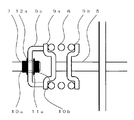
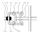
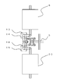
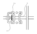
- FIG. 2 is a structural diagram illustrating a connection state between an electromagnetic operating mechanism drive shaft and a main circuit contact movable shaft in a main circuit contact closed state, and is a partially enlarged view of FIG. 1. It is a structural diagram showing the connection state of the electromagnetic operating mechanism drive shaft and the main circuit contact movable shaft in the main circuit contact open state. It is a structural diagram showing the connection state of the electromagnetic operating mechanism drive shaft and the main circuit contact movable shaft. It is a structural diagram showing a contact pressure spring using a coil spring. It is a structural diagram showing a connection state using an angle conversion link for connection between the electromagnetic operating mechanism drive shaft and the main circuit contact movable shaft.
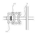
- FIG. 10 is an enlarged explanatory view of a washer-shaped contact consumption amount indicator in a contact consumption state in a main circuit contact closed state.
- FIG. 1 is an overall configuration diagram for one phase of an electromagnetically operated switch in a main circuit contact closed state, and is provided in each phase.
- the main circuit contact 1 arranged to be openable / closable is composed of a movable side main circuit contact 1a and a fixed side main circuit contact 1b.
- the main circuit contact 1 opens and closes in a vacuum, for example.
- the movable side main circuit contact 1a is connected to the movable side terminal 3 through the flexible conductor 2, and is connected to the insulating rod 4 and the main circuit contact movable shaft 5 to electrically insulate the main circuit.
- the contact pressure spring receiver 9a, the main circuit contact side contact pressure spring receiver 9b, and the contact pressure spring 6 held by the spring receiver connection fitting 9c are connected to the electromagnetic operation mechanism 8 that drives the electromagnetic operation mechanism drive shaft 7. .
- the fixed-side main circuit contact 1 b is connected to the fixed-side terminal 21.
- FIG. 2 is an enlarged view showing the vicinity of the electromagnetic operating mechanism drive shaft 7 and the contact pressure spring 6
- FIG. 3 is an enlarged view showing the vicinity of the electromagnetic operating mechanism drive shaft 7 and the contact pressure spring 6 in the main circuit contact open state.
- the electromagnetic operating mechanism drive shaft 7 has nuts 10a and 10b fixed to both sides of the spring support fitting 9c, and is provided with a gap 11a or 11b of about 0.1 mm.
- the nut 10a or 10b and the spring receiving connection fitting 9c are in contact with each other.
- the nut 10a and the spring receiving connection fitting 9c are in contact with each other at the contact portion 12a.
- the spring receiving connection fitting 9c is in contact with the contact portion 12b.
- the main circuit contact is in a closed state, and the electromagnetic operation mechanism 8 pushes the contact pressure spring 6 through the contact portion 12a with the electromagnetic operation mechanism drive shaft 7 and the nut 10a to contact the main circuit contact 1.
- the electromagnetic operating mechanism drive shaft 7 starts to move in a direction in which the movable side main circuit contact 1a is separated from the fixed side main circuit contact 1b.
- the pressing of the contact pressure spring 6 is released, and when the pressing completely disappears, the movable side main circuit contact 1 a starts to operate via the main circuit contact movable shaft 5.
- the movable main circuit contact 1a moves to the open state, for example, when the main circuit contact 1 opens and closes in a vacuum, a self-closing force due to vacuum pressure acts on the movable main circuit contact 1a.
- the metal fitting 9c and the nut 10b come into contact with each other at the contact portion 12b, and a gap 11b of about 0.1 mm is formed.
- Example 1 the nut 10a or 10b and the spring support fitting 9c are in contact with each other, and when the main circuit contact is closed, the nut 10a and the spring support connection fitting 9c are in contact with each other at the contact portion 12a.
- the main circuit contact is in the open state, the nut 10b and the spring receiving connection fitting 9c are in contact with each other at the contact portion 12b, so that the axis of the electromagnetic operation mechanism drive shaft 7 and the main circuit contact movable shaft 5 are not aligned. It is possible to suppress the unbalanced load on the drive shaft of the electromagnetic operation mechanism section resulting from the stabilization of the operation of the electromagnetic operation type switchgear.
- FIG. 5 is a structural diagram of the contact pressure spring 6 using a coil spring, in which the coil winding start end portion 6 a and the coil winding end end portion 6 b are shifted by an angle of 180 ° in the circumferential direction of the contact pressure spring 6. is there.
- Example 2 the coil winding start end portion 6a and the coil winding end end portion 6b of the contact pressure spring 6 are shifted in the circumferential direction of the contact pressure spring 6 at an angle of 180 °.
- the coil winding start end 6a and the coil winding end 6b which are singular points of the coil spring, are shifted to a symmetrical position with respect to the coil spring central axis, and the coil resulting from the coil winding start 6a and the coil winding end 6b
- the fall of the spring can be suppressed, and the occurrence of an unbalanced load applied to the electromagnetic operating mechanism drive shaft can be suppressed.
- FIG. 6 is a structural diagram showing a connection state in which the angle conversion link 13 is used for connection between the electromagnetic operating mechanism drive shaft 7 and the main circuit contact movable shaft 5, and the electromagnetic operating mechanism drive shaft 7 and the contact pressure spring 6 or insulation.
- An electromagnetic operation mechanism drive shaft 7 and a main shaft are connected to each other by using an angle conversion link 13 that converts a connection angle with a main circuit contact movable shaft 5 that is connected to a rod 4 (not shown) and opens and closes a main circuit contact 1 (not shown).
- the circuit contact movable shaft 5 is connected at an angle of 90 °.
- a rotary auxiliary contact 14 used for detecting an open state and a closed state of the electromagnetic operation type switchgear is directly attached to the angle conversion link 13.
- Example 3 the main circuit contact movable shaft 5 connected to the electromagnetic operation mechanism drive shaft 7 and the contact pressure spring 6 or the insulating rod 4 (not shown) to open and close the main circuit contact 1 (not shown). Since the electromagnetic operation mechanism unit drive shaft and the main circuit contact movable shaft are connected at an angle of 90 ° using the angle conversion link 13 that converts the connection angle with the main circuit contact 1 (not shown), It is not necessary to arrange the insulating rod 4 (not shown), the contact pressure spring 6, and the electromagnetic operating mechanism 8 on one axis, and the overall length of the electromagnetic operating switchgear can be shortened. The installation space can be reduced.
- FIG. 7 is a structural diagram showing a state in which the electromagnetic operation mechanism 8 and the angle conversion link 13 are arranged symmetrically with respect to the main circuit contact movable shaft 5.
- Example 4 As described above, in Example 4, the same effects as in Example 3 are obtained, and the ratings of the electromagnetically operated switchgear such as an increase in the opening distance of the electromagnetically operated switchgear and an increase in contact pressure spring load are different. Even when it becomes necessary to deal with things, it is possible to easily increase the number of electromagnetic operation mechanisms, and it is easy to change to various ratings.
- FIG. 8 is a structural diagram showing the washer-like contact consumption amount indicator 15 in the main circuit contact closed state
- FIG. 9 is a structural diagram showing the washer-like contact consumption amount indicator in the contact consumption state in the main circuit contact closed state.
- the washer-like contact consumption amount indicator 15 is provided on the main circuit contact movable shaft 5, and the main circuit contact between the electromagnetic operation mechanism side contact pressure spring receiver 9 a and the washer-like contact consumption amount indicator 15 in the closed state of the electromagnetic operation type switching device.
- Example 5 when the contact consumption amount of the main circuit contact is measured by inspection of the electromagnetic operation type switchgear, the need for a special measuring instrument or jig is eliminated, and the contact consumption amount is measured. Labor saving work is possible.
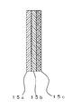
- FIG. 10 shows an example of use of the washer-like contact consumption amount indicator 15.
- the washer-like contact consumption amount indicator 15 is divided into three parts, ie, “required replacement” display area 15a, “caution” display area 15b, and “normal” display area 15c. Easily determine the amount of contact wear by monitoring the above area of the washer-like contact wear amount indicator 15 protruding from the electromagnetic operating mechanism side contact pressure spring receiver 9a shown in FIGS. It becomes possible to do.
Landscapes
- Physics & Mathematics (AREA)
- Electromagnetism (AREA)
- Driving Mechanisms And Operating Circuits Of Arc-Extinguishing High-Tension Switches (AREA)
Abstract
Priority Applications (5)
| Application Number | Priority Date | Filing Date | Title |
|---|---|---|---|
| JP2011538114A JP5249424B2 (ja) | 2009-10-29 | 2009-10-29 | 電磁操作方式開閉装置 |
| KR1020127004231A KR101275948B1 (ko) | 2009-10-29 | 2009-10-29 | 전자조작방식 개폐장치 |
| HK12112266.8A HK1171563B (zh) | 2009-10-29 | 电磁操作式开关装置 | |
| PCT/JP2009/005737 WO2011052009A1 (fr) | 2009-10-29 | 2009-10-29 | Dispositif de commutation à commande électromagnétique |
| CN200980162301.1A CN102598179B (zh) | 2009-10-29 | 2009-10-29 | 电磁操作式开关装置 |
Applications Claiming Priority (1)
| Application Number | Priority Date | Filing Date | Title |
|---|---|---|---|
| PCT/JP2009/005737 WO2011052009A1 (fr) | 2009-10-29 | 2009-10-29 | Dispositif de commutation à commande électromagnétique |
Publications (1)
| Publication Number | Publication Date |
|---|---|
| WO2011052009A1 true WO2011052009A1 (fr) | 2011-05-05 |
Family
ID=43921454
Family Applications (1)
| Application Number | Title | Priority Date | Filing Date |
|---|---|---|---|
| PCT/JP2009/005737 Ceased WO2011052009A1 (fr) | 2009-10-29 | 2009-10-29 | Dispositif de commutation à commande électromagnétique |
Country Status (4)
| Country | Link |
|---|---|
| JP (1) | JP5249424B2 (fr) |
| KR (1) | KR101275948B1 (fr) |
| CN (1) | CN102598179B (fr) |
| WO (1) | WO2011052009A1 (fr) |
Families Citing this family (2)
| Publication number | Priority date | Publication date | Assignee | Title |
|---|---|---|---|---|
| JP2743641B2 (ja) | 1991-08-20 | 1998-04-22 | 松下電器産業株式会社 | 触媒浄化装置 |
| JP6214844B2 (ja) * | 2015-08-31 | 2017-10-18 | 三菱電機株式会社 | 開極速度調整機構及びスイッチギヤ |
Citations (10)
| Publication number | Priority date | Publication date | Assignee | Title |
|---|---|---|---|---|
| JPH0366124U (fr) * | 1989-11-01 | 1991-06-27 | ||
| JPH0479117A (ja) * | 1990-07-19 | 1992-03-12 | Fuji Electric Co Ltd | ガス絶縁開閉装置 |
| JPH07169373A (ja) * | 1993-12-14 | 1995-07-04 | Fuji Electric Co Ltd | 真空バルブ接点消耗量測定装置 |
| JPH08287796A (ja) * | 1995-04-18 | 1996-11-01 | Mitsubishi Electric Corp | 真空電磁接触器 |
| JPH09147703A (ja) * | 1995-11-27 | 1997-06-06 | Mitsubishi Electric Corp | 真空遮断器 |
| JP2000170809A (ja) * | 1998-12-09 | 2000-06-23 | Canon Inc | 圧縮コイルバネ |
| JP2004236455A (ja) * | 2003-01-31 | 2004-08-19 | Hitachi Ltd | ガス絶縁開閉装置 |
| JP2006107860A (ja) * | 2004-10-04 | 2006-04-20 | Toshiba Corp | 開閉器およびその操作機構 |
| JP2007123230A (ja) * | 2005-09-30 | 2007-05-17 | Mitsubishi Electric Corp | 電磁操作方式開閉器 |
| JP2009049231A (ja) * | 2007-08-21 | 2009-03-05 | Mitsubishi Electric Corp | 電磁石装置、及び電磁操作開閉装置 |
Family Cites Families (2)
| Publication number | Priority date | Publication date | Assignee | Title |
|---|---|---|---|---|
| JP2002124162A (ja) * | 2000-10-16 | 2002-04-26 | Mitsubishi Electric Corp | 開閉装置 |
| JP2004220999A (ja) * | 2003-01-17 | 2004-08-05 | Mitsubishi Electric Corp | 密閉型開閉装置 |
-
2009
- 2009-10-29 JP JP2011538114A patent/JP5249424B2/ja not_active Expired - Fee Related
- 2009-10-29 CN CN200980162301.1A patent/CN102598179B/zh not_active Expired - Fee Related
- 2009-10-29 WO PCT/JP2009/005737 patent/WO2011052009A1/fr not_active Ceased
- 2009-10-29 KR KR1020127004231A patent/KR101275948B1/ko not_active Expired - Fee Related
Patent Citations (10)
| Publication number | Priority date | Publication date | Assignee | Title |
|---|---|---|---|---|
| JPH0366124U (fr) * | 1989-11-01 | 1991-06-27 | ||
| JPH0479117A (ja) * | 1990-07-19 | 1992-03-12 | Fuji Electric Co Ltd | ガス絶縁開閉装置 |
| JPH07169373A (ja) * | 1993-12-14 | 1995-07-04 | Fuji Electric Co Ltd | 真空バルブ接点消耗量測定装置 |
| JPH08287796A (ja) * | 1995-04-18 | 1996-11-01 | Mitsubishi Electric Corp | 真空電磁接触器 |
| JPH09147703A (ja) * | 1995-11-27 | 1997-06-06 | Mitsubishi Electric Corp | 真空遮断器 |
| JP2000170809A (ja) * | 1998-12-09 | 2000-06-23 | Canon Inc | 圧縮コイルバネ |
| JP2004236455A (ja) * | 2003-01-31 | 2004-08-19 | Hitachi Ltd | ガス絶縁開閉装置 |
| JP2006107860A (ja) * | 2004-10-04 | 2006-04-20 | Toshiba Corp | 開閉器およびその操作機構 |
| JP2007123230A (ja) * | 2005-09-30 | 2007-05-17 | Mitsubishi Electric Corp | 電磁操作方式開閉器 |
| JP2009049231A (ja) * | 2007-08-21 | 2009-03-05 | Mitsubishi Electric Corp | 電磁石装置、及び電磁操作開閉装置 |
Also Published As
| Publication number | Publication date |
|---|---|
| CN102598179B (zh) | 2014-12-17 |
| HK1171563A1 (en) | 2013-03-28 |
| KR20120036368A (ko) | 2012-04-17 |
| JP5249424B2 (ja) | 2013-07-31 |
| KR101275948B1 (ko) | 2013-06-17 |
| CN102598179A (zh) | 2012-07-18 |
| JPWO2011052009A1 (ja) | 2013-03-14 |
Similar Documents
| Publication | Publication Date | Title |
|---|---|---|
| JP5471925B2 (ja) | 接地開閉器付断路器 | |
| US8207459B2 (en) | Mold cased circuit breaker | |
| US9196436B2 (en) | Ring main unit circuit breaker equipped with contact force controller | |
| JP5418715B1 (ja) | 開閉器 | |
| CN106960740B (zh) | 具有悬浮式活动触头组件的开关装置 | |
| JP5249424B2 (ja) | 電磁操作方式開閉装置 | |
| JP4174495B2 (ja) | スイッチギヤの開閉装置 | |
| JPWO2011086670A1 (ja) | 電磁操作方式開閉装置 | |
| US20150325386A1 (en) | Control device of the spring type particularly for a high-voltage or medium-voltage circuit breaker or switch | |
| US10832881B2 (en) | Medium voltage switching apparatus | |
| US7297890B2 (en) | Earthing switch | |
| CN103026439A (zh) | 用于带有c o-开关能力的断路开关的驱动装置 | |
| JP4901621B2 (ja) | 開閉装置 | |
| HK1171563B (zh) | 电磁操作式开关装置 | |
| CN114038708A (zh) | 一种单相断路器传动机构及具有其的操作机构 | |
| RU2273072C1 (ru) | Вакуумный контактор | |
| CA2870089C (fr) | Module de liaison autonome pour des disjoncteurs de type dead tank a tension elevee du type a couplage | |
| US20260074129A1 (en) | Switching unit for electrical applications | |
| EP1280177B1 (fr) | Disjoncteur basse tension | |
| JPH04359821A (ja) | 開閉器の操作リンク機構 | |
| HK1098247B (en) | Device for controlling the opening/closing operation of an electric switchgear |
Legal Events
| Date | Code | Title | Description |
|---|---|---|---|
| WWE | Wipo information: entry into national phase |
Ref document number: 200980162301.1 Country of ref document: CN |
|
| 121 | Ep: the epo has been informed by wipo that ep was designated in this application |
Ref document number: 09850789 Country of ref document: EP Kind code of ref document: A1 |
|
| WWE | Wipo information: entry into national phase |
Ref document number: 2011538114 Country of ref document: JP |
|
| ENP | Entry into the national phase |
Ref document number: 20127004231 Country of ref document: KR Kind code of ref document: A |
|
| NENP | Non-entry into the national phase |
Ref country code: DE |
|
| 122 | Ep: pct application non-entry in european phase |
Ref document number: 09850789 Country of ref document: EP Kind code of ref document: A1 |