WO2011052541A1 - Dispositif de test et procédé de test - Google Patents
Dispositif de test et procédé de test Download PDFInfo
- Publication number
- WO2011052541A1 WO2011052541A1 PCT/JP2010/068861 JP2010068861W WO2011052541A1 WO 2011052541 A1 WO2011052541 A1 WO 2011052541A1 JP 2010068861 W JP2010068861 W JP 2010068861W WO 2011052541 A1 WO2011052541 A1 WO 2011052541A1
- Authority
- WO
- WIPO (PCT)
- Prior art keywords
- preform
- scattered light
- forward scattered
- hole
- inspection apparatus
- Prior art date
- Legal status (The legal status is an assumption and is not a legal conclusion. Google has not performed a legal analysis and makes no representation as to the accuracy of the status listed.)
- Ceased
Links
Images







Classifications
-
- G—PHYSICS
- G01—MEASURING; TESTING
- G01M—TESTING STATIC OR DYNAMIC BALANCE OF MACHINES OR STRUCTURES; TESTING OF STRUCTURES OR APPARATUS, NOT OTHERWISE PROVIDED FOR
- G01M11/00—Testing of optical apparatus; Testing structures by optical methods not otherwise provided for
- G01M11/30—Testing of optical devices, constituted by fibre optics or optical waveguides
- G01M11/37—Testing of optical devices, constituted by fibre optics or optical waveguides in which light is projected perpendicularly to the axis of the fibre or waveguide for monitoring a section thereof
Definitions
- the present invention relates to a preform which is a preform of an optical fiber in which holes are formed, that is, a preform inspection apparatus and a method for inspection in which a through hole is formed.
- a photonic crystal fiber is an optical fiber in which the refractive index of the cladding is reduced by holes, and it is known that optical characteristics that cannot be obtained by conventional optical fibers in which the refractive index of the cladding is reduced by impurities are obtained. It has been.
- the photonic crystal fiber includes (1) a preform manufacturing process for manufacturing a columnar base material made of silica glass (hereinafter referred to as “preform”), (2 It is manufactured through a through-hole forming step for forming a through-hole serving as a base material for holes in the preform, and (3) a drawing step for drawing the preform with the through-hole formed therein.
- preform a columnar base material made of silica glass
- through holes extending from one end surface of the preform to the other end surface in a direction perpendicular to these end surfaces are formed by drilling. For this reason, if the machining accuracy of the machine tool that forms the through hole is low, the drilling position gradually shifts as the drilling progresses even if drilling starts from an appropriate position on one end surface, and the other end surface penetrates. Large positional displacement of the holes may occur, or the through holes may be connected on the way. For this reason, after forming a through-hole, it is necessary to test
- the inspection of whether or not the through-hole is formed at an appropriate position is generally performed by a method of observing the preform from the end surface direction using an optical microscope.
- Japanese Published Patent Publication “JP 2002-145634” (published on May 22, 2002) Japanese Patent Publication “JP 2002-249335” (published on September 6, 2002) Japanese Patent Publication “JP 2002-293562 A” (published on October 9, 2002) Japanese Patent Publication “Japanese Patent Laid-Open No. 2006-160528” (published on June 22, 2006)
- the conventional inspection method using an optical microscope has a problem that it can inspect only the formation positions of holes near the end face of the preform. That is, there has been a problem that the formation position of the through hole cannot be inspected in the middle of both end faces (arbitrary cross section between both end faces).
- An intermediate through-hole formation position is also estimated from a hole formation position on one end face and a hole formation position on the other end face. The position where the hole is formed cannot be specified with high accuracy. For this reason, when the through hole formation position on the end face is greatly deviated from the proper position, it is necessary to examine which part can be used for manufacturing an optical fiber by cutting the preform. This increases the manufacturing cost.
- the present invention has been made in view of the above problems, and its purpose is to determine whether or not the through hole is formed at an appropriate position in the middle of both end faces of the preform without destroying the preform.
- the object is to realize an inspection apparatus and inspection method that can be confirmed well.
- an inspection apparatus is an inspection apparatus that inspects a cylindrical preform having a through-hole, and is generated by allowing light to enter from a side surface of the preform.
- Detection means for successively detecting the intensity distribution of the forward scattered light of the preform, and rotating the preform around the center axis of the preform or moving the detection means so as to go around the preform
- Rotating / moving means for calculating, and calculating means for calculating a time series of feature values having values corresponding to the arrangement of the through holes from the intensity distribution of the forward scattered light detected sequentially. It is said.
- inspection method which concerns on this invention is a test
- a rotation / movement step for moving the detection means a calculation step for calculating a time series of feature amounts having values corresponding to the arrangement of the through holes from the intensity distribution of the forward scattered light detected sequentially, and the features And a determination step of determining whether or not the through hole is formed at a predetermined position based on a time series of quantities.
- the time series of feature values calculated from the intensity distribution of the forward scattered light detected sequentially while rotating the preform around the central axis or moving the detection means to circulate around the preform is the through hole. It shows different behavior depending on whether it is formed at an appropriate position. For this reason, referring to the time series of the feature amounts, it can be accurately confirmed whether or not the through hole is formed at a predetermined position without destroying the preform.
- the upper stage is a graph showing the intensity distribution of forward scattered light obtained when a parallel light beam is irradiated to a preform having no through-holes
- the lower stage is a cross-sectional view of such a preform.
- the upper row is a graph showing the intensity distribution of forward scattered light obtained when parallel rays are irradiated to a preform having through holes formed at appropriate positions
- the lower row is a cross-sectional view of such a preform. It is.
- the upper graph is a graph showing the intensity distribution of forward scattered light obtained when a parallel beam is irradiated to a preform in which one through-hole is displaced, and the lower graph is a cross section of such a preform.
- FIG. The upper graph is a graph showing the intensity distribution of forward scattered light obtained when a parallel beam is irradiated to a preform in which two through holes are displaced, and the lower graph is a cross section of such a preform.
- FIG. It is sectional drawing of the ideal preform in which all the through-holes were formed in the appropriate position. It is a graph which shows the time series of the dark part width
- FIG. 5 is a graph showing a time series of dark part widths in the intensity distribution of forward scattered light obtained by rotating the preform shown in the lower part of FIG. 4. It is a graph which shows the time series of the dark part width
- the upper graph is a graph showing the intensity distribution of forward scattered light obtained when a parallel beam is irradiated to a preform in which all the through holes are uniformly displaced, and the lower graph is a graph showing such a profile. It is sectional drawing of reform.
- the upper graph is a graph showing the intensity distribution of forward scattered light obtained when parallel rays are irradiated to a preform in which all through holes are formed at appropriate positions
- the lower graph is a graph of such a preform. It is sectional drawing.
- the upper graph is a graph showing the intensity distribution of forward scattered light obtained when a parallel beam is irradiated to a preform in which all the through holes are uniformly displaced
- the lower graph is a graph showing such a profile. It is sectional drawing of reform.
- the upper graph is a graph showing the intensity distribution of forward scattered light obtained when parallel rays are irradiated to a preform in which all through holes are formed at appropriate positions
- the lower graph is a graph of such a preform.
- the upper graph is a graph showing the intensity distribution of forward scattered light obtained when a parallel beam is irradiated to a preform in which all the through holes are uniformly displaced, and the lower graph is a graph showing such a profile. It is sectional drawing of reform.
- the upper graph is a graph showing the intensity distribution of forward scattered light obtained when parallel rays are irradiated to a preform in which all through-holes are shifted by 3 mm from the preform central axis. It is sectional drawing of such a preform.
- 12 is a graph showing a time series of an integral value difference
- FIG. 16 is a graph showing a time series of an integral value difference
- FIG. 14 is a graph showing a time series of a bright part width difference
- FIG. 15 is a graph showing a time series of a bright portion width difference
- optical fiber in each embodiment described below refers to an optical fiber in which one or more holes extending in the central axis direction are formed unless otherwise specified.
- preform a preform that is a base material of an optical fiber in which one or more holes are formed, that is, one or more penetrations. It refers to a preform in which holes are formed.
- the inspection apparatus is an inspection apparatus suitable for detecting a positional shift that has occurred in some of the through holes formed in the preform.
- FIG. 1 is a schematic configuration diagram illustrating a schematic configuration of an inspection apparatus 100 according to the present embodiment.
- the inspection apparatus 100 is an apparatus for inspecting whether or not the through hole 11 is formed at a predetermined appropriate position in each cross section of the preform 10, and as shown in FIG. Device (detecting means) 102, rotating mechanism (rotating / moving means) 103, parallel moving mechanism (parallel moving means) 104, computing unit 105 (calculating means), determining unit 106, and position detecting unit 107.
- the light source 101 is a means for irradiating the preform 10 with parallel rays from the side surface, and is, for example, an LED (Light Emitting Diode).
- the parallel rays irradiated to the preform 10 are repeatedly refracted and reflected at the boundary separating the inside and outside of the preform 10 and the boundary separating the inside and outside of the through hole 11, and forward on the opposite side of the preform 10 from the light source 101 side. This produces scattered light.
- the forward scattered light generated in this way is hereinafter simply referred to as “forward scattered light of the preform 10”.
- the detector 102 is means for sequentially detecting the intensity distribution of the forward scattered light of the preform 10. More specifically, in a plane opposite to the light source 101 side of the preform 10 and orthogonal to the parallel rays irradiated from the light source 101, the plane is orthogonal to the orthogonal projection of the central axis of the preform 10. This is means for sequentially detecting the intensity distribution on the straight line.
- a detector 102 can be realized, for example, by arranging a CCD (Charge-Coupled Device) line sensor along this straight line.
- the rotation mechanism 103 is a means for rotating the preform 10 gripped by the grip portion 103a with the central axis (of the preform 10) as the rotation axis. By rotating the preform 10 using the rotation mechanism 103, it becomes possible to sequentially detect the forward scattered light of the preform 10 in each direction. Instead of adopting a configuration in which the preform 10 is rotated using the rotation mechanism 103 as in the present embodiment, a configuration in which the light source 101 and the detector 102 are moved so as to go around the preform 10 is the same. It becomes possible.
- the translation mechanism 104 is a means for translating the light source 101 and the detector 102 held by the holding unit 104a in the central axis direction of the preform 10. While the preform 10 is rotated about the central axis using the rotation mechanism 103, the light source 101 and the detector 102 are translated using the parallel movement mechanism 104, whereby forward scattered light of the preform 10 in each direction. Can be detected for each cross section.
- the preform 10 is moved in the central axis direction. The same can be achieved even if the configuration is adopted.
- the intensity distribution of the forward scattered light of the preform 10 has a dark portion corresponding to the “shadow” of the through hole 11 as described later.
- the computing unit 105 is means for sequentially calculating the width of the dark part (hereinafter abbreviated as “dark part width”) from the intensity distribution of the forward scattered light sequentially detected by the detector 102.
- the determination unit 106 is a unit for determining whether or not the through hole 11 is formed at a predetermined appropriate position based on the time series of the dark part width sequentially calculated by the calculation unit 105. Note that a method for determining whether or not the through hole 11 is formed at a predetermined appropriate position based on the time series of the dark part width will be described later with reference to another drawing.
- the position detector 107 is a means for detecting the positions of the light source 101 and the detector 102.
- the determination unit 106 outputs or records a determination result indicating whether or not the through-hole 11 is properly arranged in association with the positions of the light source 101 and the detector 102 detected by the position detection unit 107. Therefore, by referring to the information output or recorded by the determination unit 106, it is possible to know in which cross section of the preform 10 the arrangement of the through holes 11 is disturbed.
- FIG. 2 The upper part of FIG. 2 is a graph showing the intensity distribution of the forward scattered light obtained when the parallel light beam 20 is irradiated to the preform 10 ′ in which no through-hole is formed, and the lower part of FIG. 2 is a cross-sectional view of a preform 10 ′.
- the parallel light beam 20 incident on the preform 10 ′ is refracted when entering the preform 10 ′ from the air and when entering the air from the preform 10 ′.
- the other side of the reform 10 ' is reached.
- the intensity distribution of the forward scattered light of the preform 10 ' becomes a smooth intensity distribution having one peak at the center as shown in the upper part of FIG.
- FIG. 3 The upper part of FIG. 3 is a graph showing the intensity distribution of the forward scattered light obtained when the parallel light beam 20 is applied to the preform 10 in which the through-holes 11 are formed at appropriate positions, and the lower part of FIG. FIG. 2 is a cross-sectional view of such a preform 10.
- the intensity distribution of the forward scattered light of the preform 10 is an intensity distribution having two peaks and a dark part sandwiched between these two peaks, as shown in the upper part of FIG.
- the “dark width” refers to the distance between these two peaks.
- the dark portion width periodically changes.
- the through-hole 11 is arranged on the apex of a regular hexagon centering on the central axis of the preform 10, it passes through the central axis of the preform 10 and is perpendicular to the parallel light beam 20.
- the dark part width takes the maximum value L 0 and the two through-holes 11 are simultaneously formed on the straight line passing through the central axis of the preform 10 and parallel to the parallel light beam 20.
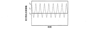
- the dark space width takes the minimum value. If the time series of the dark part width obtained when the preform 10 is rotated as shown in the lower part of FIG. 3 is plotted, a sine waveform is obtained as shown in FIG.
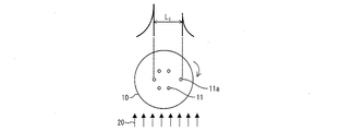
- FIG. 4 The upper part of FIG. 4 is a graph showing the intensity distribution of the forward scattered light obtained when the parallel light beam 20 is irradiated to the preform 10 in which one through hole 11a is displaced.
- the lower part of FIG. These are sectional views of such a preform 10. The point where the intensity distribution of the forward scattered light has two peaks and a dark part sandwiched between these two peaks is the case where the through hole 11 is formed at an appropriate position as shown in the upper part of FIG. It is the same.
- the lower preform 10 in FIG. 4 is different from the lower preform 10 in FIG. 3 in that one through hole 11a is formed to be shifted outward. Therefore, passing through the central axis of the preform 10, the dark area width when the through-hole 11a that misaligned perpendicular straight line into parallel beams 20 are arranged to take the maximum value L 1 (L 1> L 0 ).
- L 1 L 1> L 0
- the through hole 11 a when the through hole 11 a is formed so as to be displaced inward, the through hole 11 a causing the positional displacement is arranged on a straight line that passes through the central axis of the preform 10 and is perpendicular to the parallel light beam 20.
- the dark part width at the time does not reach the maximum value.
- the upper part of FIG. 5 is a graph showing the intensity distribution of forward scattered light obtained when the preform 10 in which the two through-holes 11a and 11b are displaced is irradiated with a parallel light beam.
- the lower part is a cross-sectional view of such a preform 10.
- the through hole 11 is formed at an appropriate position in that the intensity distribution of the forward scattered light has two peaks and an intensity distribution having a dark part sandwiched between these two peaks. It is the same as if
- the lower preform 10 in FIG. 5 differs from the lower preform 10 in FIG. 3 and the lower preform 10 in FIG. 4 in that two through-holes 11 a and 11 b that are opposed to each other via the central axis are formed to be shifted outward. . Therefore, passing through the central axis of the preform 10, the vertical straight line into parallel beams 20, dark portion width when the two through holes 11a ⁇ b are misaligned is disposed a maximum value L 2 (L 2> L 1> L 0).
- L 2 L 2> L 1> L 0
- the through holes 11a and 11b are formed to be displaced inwardly, the through holes 11a and 11b that are misaligned are on a straight line that passes through the central axis of the preform 10 and is perpendicular to the parallel light beam 20.
- the dark portion width when placed in the position does not reach the maximum value.
- FIG. 6 is a cross-sectional view of an ideal preform 10 in which all through holes 11 are formed at appropriate positions.
- the through hole 11 formed in the ideal preform 10 shown in FIG. 6 deviates from an appropriate position to the outside, the dark portion width obtained when the preform 10 is rotated once.
- the maximum value L of the series becomes larger than the maximum value L 0 of the time series of the dark part width obtained when the ideal preform 10 is rotated once.
- the determination unit 106 extracts (1) the time series maximum value L of the dark part width calculated by the calculation unit 105, (2) compares the extracted maximum value L with the threshold Th, and (3) When the extracted maximum value L is larger than the threshold value Th, it is possible to detect that the through-hole 11 has shifted outward from an appropriate position by determining that the “through-hole 11 has shifted outward”.
- the inspection apparatus 100 can be realized.
- the time series maximum value L 0 of the dark part width obtained when the ideal preform 10 is rotated once may be determined by actual measurement or opposed to the ideal preform 10 via the central axis.
- the determination unit 106 (1) extracts all the maximum values included in the time series of the dark portion width calculated by the calculation unit 105, and (2) compares each of the extracted maximum values with the threshold Th. (3) If it is determined that “the through hole 11 is displaced inward” when a maximum value smaller than the threshold Th is present, the through hole 11 may be displaced inward from an appropriate position.
- a detectable inspection apparatus 100 can be realized.
- the determination method for determining that the through-hole 11 is not formed at a predetermined position when the time series of the dark part width has a maximum value exceeding a predetermined threshold has been described. Is not limited to this.
- the time series of the dark part width shows a sine waveform as shown in FIG.
- the waveform is broken as shown in FIGS. Therefore, the time-series frequency spectrum (with one sharp peak) of the dark part width obtained when the ideal preform 10 is rotated once is stored in advance in the memory provided in the determination unit 106. By comparing with the frequency spectrum calculated by the calculation unit 105, it can be appropriately determined whether or not the through hole is formed at an appropriate position.
- the inspection apparatus is an inspection apparatus that inspects a cylindrical preform having a through-hole formed therein, and the above-described profile generated by making a light beam incident from the side surface of the preform.
- Detection means for sequentially detecting the intensity distribution of the forward scattered light of the reform, and rotation for rotating the preform around the center axis of the preform or moving the detection means so as to go around the preform / Moving means, and calculating means for calculating a time series of the dark width from the intensity distribution of the forward scattered light detected sequentially.
- the inspection method is an inspection method for inspecting a cylindrical preform in which a through-hole is formed, and the front of the preform generated by allowing light to enter from a side surface of the preform.
- a dark portion corresponding to the formation position of the through hole is generated in the intensity distribution of the forward scattered light.
- the time series of the dark part width in the intensity distribution of the forward scattered light is: It behaves differently depending on whether or not the through hole is formed at an appropriate position. For this reason, referring to the time series of the dark portion width in the intensity distribution of the forward scattered light calculated by the above configuration, whether the through hole is formed at a predetermined position or not is determined as follows. There is an effect that it can be confirmed with high accuracy without destruction.
- the inspection apparatus further includes a translation unit that translates the preform or the detection unit in the central axis direction of the preform.
- the inspection apparatus compares the time series maximum value or maximum value of the dark part width with a predetermined threshold value to determine whether the through hole is formed at a predetermined position. It is preferable to further comprise determination means for determining.
- the through holes formed in the preform are usually arranged at equal intervals on the circumference centered on the central axis of the preform in order to provide the optical fiber with axial symmetry.
- the maximum value of the time series of the dark part width obtained when the preform is rotated once all the through holes are on the circumference. It becomes larger than the time series maximum value of the dark part width obtained when the formed preform is rotated once. Further, when any of the through holes is displaced inward from the circumference, all the through holes are formed on the circumference in a time series of dark portion widths obtained when the preform is rotated once. A maximum value that does not reach the maximum value of the time series of the dark width obtained when the preform is rotated once appears.
- the time series maximum value of the dark part width obtained when the preform having the through hole formed on the circumference is rotated once is set as a threshold value
- the time series maximum value of the dark part width is determined. Can be accurately determined whether or not the through hole is formed at a predetermined position. Further, when any of the through holes is shifted inward from the circumference, the through hole is formed at a predetermined position by comparing each time series maximum value of the dark portion with this threshold value. It can be accurately determined whether or not there is.
- the inspection apparatus determines whether or not the through hole is formed at a predetermined position by comparing the time-series frequency spectrum of the dark part width with a predetermined frequency spectrum. It is preferable to further comprise determination means.
- the through holes formed in the preform are usually arranged at equal intervals on the circumference centered on the central axis of the preform in order to provide the optical fiber with axial symmetry.
- the time series of the dark part width shows a sine waveform, and when the position shift occurs in the through hole, the time series of the dark part width becomes a sine waveform collapsed. Therefore, by comparing the time-series frequency spectrum of the dark part width with the spectrum of the dark part width obtained when the preform having the through holes arranged at equal intervals on the circumference is rotated once, the through hole becomes circular. There is an effect that it can be accurately determined whether or not they are arranged at equal intervals on the circumference.
- this embodiment A second embodiment (hereinafter referred to as “this embodiment”) of the present invention will be described with reference to FIGS. 10 to 14 and FIGS. 16 to 19.
- the inspection apparatus according to the present embodiment is an inspection apparatus suitable for detecting a uniform positional deviation generated in all through holes formed in the preform.
- FIG. 10 shows a mode of misalignment to be detected in this embodiment.
- the lower part of FIG. 10 is a cross-sectional view of the preform 10 in which all the through holes 11 ′ are uniformly displaced, and the upper part of FIG. 10 shows the parallel light beam 20 with respect to such a preform 10.
- It is a graph which shows intensity distribution of the forward scattered light obtained when it irradiates. As shown in the upper part of FIG. 10, the point that the intensity distribution of the forward scattered light has two peaks and a dark part sandwiched between these two peaks is the same as described above.
- the bright portion of the forward scattered light refers to a region where the intensity of the forward scattered light spreads outside the two peaks and becomes greater than a predetermined intensity Io (explanation).
- a predetermined intensity Io explanation
- the bright part spreading to the left of the dark part is referred to as “first bright part” and the bright part spreading to the right of the dark part is referred to as “second bright part”).
- the lower limit intensity Io that defines the left end of the first bright part and the right end of the second bright part can be set to an arbitrary value of 0 or more.
- the configuration of the inspection apparatus according to this embodiment is the same as that of the inspection apparatus 100 in the first embodiment shown in FIG.
- the calculation unit 105 sequentially calculates the bright part width difference ⁇ W from the intensity distribution of the forward scattered light sequentially detected by the detector 102, A configuration is employed in which the determination unit 106 determines whether or not the through hole 11 is formed at an appropriate position based on the time series of the bright part width difference ⁇ W sequentially calculated by the calculation unit 105.
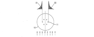
- FIG. 11 is a cross-sectional view of such a preform 10
- the upper part of FIG. 11 shows the intensity distribution of forward scattered light obtained when such a preform 10 is irradiated with parallel rays 20. It is a graph to show.
- the area on the graph having an area corresponding to the integrated value S1 obtained by integrating the intensity of the forward scattered light on the first bright portion, and the intensity of the forward scattered light are the second A region on the graph having an area corresponding to the integral value S2 obtained by integrating on the bright part is clearly indicated by hatching.
- the intensity of the forward scattered light is integrated on the first bright part as shown in the upper part of FIG.
- the obtained integrated value S1 and the integrated value S2 obtained by integrating the intensity of the forward scattered light on the second bright portion are substantially equal. Even if the preform 10 is rotated, the intensity distribution of the forward scattered light in these two bright portions changes substantially symmetrically with respect to the central axis of the preform 10, so that the integral value S1 and the integral value S2 are substantially equal. Keep on.
- calculated by the calculation unit 105 when the preform 10 in which all the through holes 11 are formed at appropriate positions is an inspection target. . It can be seen from FIG. 16 that the maximum value of the integral value difference ⁇ S
- FIG. 12 The lower part of FIG. 12 is a cross-sectional view of such a preform 10, and the upper part of FIG. 12 shows the intensity distribution of forward scattered light obtained when such a reformer 10 is irradiated with parallel rays 20. It is a graph.
- the region on the graph having an area corresponding to the integrated value S1 obtained by integrating the intensity of the forward scattered light on the first bright portion, and the intensity of the forward scattered light are the second A region on the graph having an area corresponding to the integral value S2 obtained by integrating on the bright part is clearly indicated by hatching.
- calculated by the calculation unit 105 when the preform 10 in which all the through holes 11 ′ are uniformly displaced is the inspection target. Shown in It can be seen from FIG. 17 that each maximum value of the integral value difference ⁇ S
- calculated by the calculation unit 105 with the threshold value ⁇ So. Can be determined. Specifically, when each maximum value of the integral value difference ⁇ S
- calculated by the calculation unit 105 does not exceed the threshold value So, it is determined that the through hole is formed at an appropriate position. When any one of the integral value differences ⁇ S
- FIG. 13 is a sectional view of such a preform 10, and the upper part of FIG. 13 shows the intensity distribution of forward scattered light obtained when such a preform 10 is irradiated with parallel rays 20. It is a graph to show.
- the first bright part width W1 and the second bright part width W2 of the forward scattered light are clearly shown by the lengths of the arrows.
- the first bright part width W1 and the second bright part of the forward scattered light are obtained.
- the part width W2 is substantially equal. Even if the preform 10 is rotated, the intensity distribution of the forward scattered light in these two bright portions changes substantially symmetrically with respect to the central axis of the preform 10, so that the first bright portion width W1 and the second bright portion are changed.
- the part width W2 is kept substantially equal.
- calculated by the calculation unit 105 when the preform 10 in which all the through holes 11 are formed at appropriate positions is an inspection target. Show. It can be seen from FIG. 18 that the maximum value of the bright part width difference ⁇ W
- FIG. 14 is a cross-sectional view of such a preform 10, and the upper part of FIG. 14 shows the intensity distribution of forward scattered light obtained when such a reformer 10 is irradiated with parallel rays 20. It is a graph.
- the difference ⁇ W
- between the bright portion width W1 and the bright portion width W2 shown in the upper part of FIG. 14 takes a local maximum value.
- the time series of the bright part width difference ⁇ W
- calculated by the calculation unit 105 with a predetermined threshold value ⁇ Wo, so that the through hole is formed at an appropriate position. It can be determined whether or not. Specifically, when each local maximum value of the bright part width difference ⁇ W
- calculated by the calculation unit 105 does not exceed the threshold value Wo, it is determined that the through hole is formed at an appropriate position. When any one of the maximum values of the bright part width difference ⁇ W
- the feature quantity that can be used to detect the positional deviation of the through hole is It is not limited to. That is, any feature amount can be used as long as it is a feature amount that can be calculated from the intensity distribution of the forward scattered light and has a value corresponding to the arrangement of the through holes formed in the preform. It can be used to detect the positional deviation of
- Example 1 The effectiveness of the inspection apparatus 100 according to the first embodiment of the present invention was confirmed as follows.
- a preform A having a cross section as shown in the lower part of FIG. Specifically, for a preform having an outer diameter of 90 mm ⁇ , six through-holes having a diameter of 4 mm ⁇ were formed by a drill method at a position 20 mm from the center of the preform.
- the position where one through hole (through hole 11a in FIG. 4) is formed is shifted outward by 4 mm
- two through holes through holes in FIG. 5 are formed.
- the positions of the holes 11a and the through holes 11b) were shifted outward by 4 mm respectively.
- a time series of dark part widths related to the preform A was obtained using the inspection apparatus 100.
- the time-series acquisition of the dark part width is performed by rotating the preform A attached to the rotation mechanism 103 (with the central axis of the preform A as a rotation axis) and the light source 101 and the detector 102 attached to the parallel movement mechanism 104.
- LEDs and a CCD line sensor were used as the light source 101 and the detector 102.
- the rotation speed of the preform was set to 100 rpm
- the moving speed of the LED and the CCD line sensor was set to 10 mm / min
- the sampling period in the CCD line sensor was set to 500 milliseconds.
- the threshold value Th used for the inspection of the preforms B to C is set using this time series.
- the maximum value of the dark space width in this time series is set to L 0
- the threshold value Th is set to a value slightly larger than L 0 , specifically, L 0 +0.5 mm. If the through-hole can be accurately formed at a position 20 mm from the central axis at the time of forming the preform A, the maximum value Lo of the dark part width may be set to 40 mm without being obtained by actual measurement.
- the preforms B to C were inspected using the inspection apparatus 100 according to the first embodiment.
- the inspection is performed by rotating the preforms B to C attached to the rotating mechanism 103 (with the center axis of the preform as the rotating axis) and detecting the light source 101 attached to the parallel moving mechanism 104 and the detection.
- the vessel 102 was moved in parallel along the central axis of the preforms B to C.
- an LED and a CCD line sensor were used as the light source 101 and the detector 102, as in the actual measurement of the dark part width.
- the rotation speed of the preform was set to 100 rpm
- the moving speed of the LED and the CCD line sensor was set to 10 mm / min
- the sampling period in the CCD line sensor was set to 500 milliseconds.
- Example 2 The effectiveness of the inspection apparatus 100 according to the second embodiment of the present invention was confirmed as follows.
- a preform having a cross section as shown in the lower part of FIG. Specifically, for a preform having an outer diameter of 90 mm ⁇ , six through-holes having a diameter of 4 mm ⁇ were formed by a drill method at a position 20 mm from the center of the preform (this preform was formed by using the preform used in Example 1). Since it is the same preform as the reform A, it is also called the preform A in this embodiment).
- the integral value difference ⁇ S is the integral value S1 obtained by integrating the intensity of the forward scattered light on the first bright part and the intensity of the forward scattered light on the second bright part.
- the time series of the integral value difference ⁇ S related to the preform A was obtained using the inspection apparatus 100.
- the integral value difference ⁇ S is obtained by rotating the preform A attached to the rotating mechanism 103 and moving the light source 101 and the detector 102 attached to the parallel moving mechanism 104 along the central axis of the preform A.
- the detection was performed by detecting the intensity distribution of the forward scattered light with the detector 102.
- LEDs and a CCD line sensor were used as the light source 101 and the detector 102.
- the rotation speed of the preform was set to 100 rpm
- the moving speed of the LED and the CCD line sensor was set to 10 mm / min
- the sampling period in the CCD line sensor was set to 500 milliseconds.
- a time series shown in FIG. 16 was obtained as a time series of the integral value difference ⁇ S regarding the preform A.
- the threshold value ⁇ So used for the inspection of the preform D is set using this time series.
- the maximum value of the integrated value difference in this time series is set to ⁇ S max
- the threshold value ⁇ S o is set to a value larger than ⁇ S max , specifically, three times ⁇ S max (see the graph shown in FIG. 16).
- the vertical axis is the logarithm of the area).
- the preform D was inspected using the inspection apparatus 100.
- the preform D attached to the rotation mechanism 103 was rotated (with the central axis of the preform D as the rotation axis) and attached to the parallel movement mechanism 104, as in the actual measurement of the integral value difference ⁇ S related to the preform A.
- the light source 101 and the detector 102 were moved while being translated along the central axis of the preform D.
- the rotation speed of the preform is set to 100 rpm
- the moving speed of the LED and the CCD line sensor is set to 10 mm / min
- the sampling period in the CCD line sensor is set to 500 milliseconds, as in the actual measurement of the integral value difference ⁇ S related to the preform A.
- the time series of the dark part width calculated by the arithmetic unit 105 when the preform D is an inspection target has the waveform shown in FIG. All local maximum values in this time series exceeded the previously set threshold value ⁇ S o .
- the determination unit 106 outputs a determination that “the through hole is displaced” over the entire length direction.
- the bright part width difference ⁇ W refers to the difference
- the time series of the bright part width difference ⁇ W related to the preform A was obtained using the inspection apparatus 100.
- the bright part width difference ⁇ W is acquired by rotating the preform A attached to the rotating mechanism 103 and moving the light source 101 and the detector 102 attached to the parallel moving mechanism 104 along the central axis of the preform A.
- the intensity distribution of the forward scattered light was detected by the detector 102.
- LEDs and a CCD line sensor were used as the light source 101 and the detector 102.
- the rotation speed of the preform was set to 100 rpm
- the moving speed of the LED and the CCD line sensor was set to 10 mm / min
- the sampling period in the CCD line sensor was set to 500 milliseconds.
- the time series shown in FIG. 18 was obtained as the time series of the bright part width difference ⁇ W related to the preform A.
- the threshold ⁇ Wo used for the inspection of the preform D is set using this time series. Specifically, the maximum value of the bright part width difference in this time series is set to ⁇ W max , and the threshold value ⁇ W o is set to a value larger than ⁇ W max , specifically, three times ⁇ W max .
- the preform D was inspected using the inspection apparatus 100.
- the inspection is attached to the parallel movement mechanism 104 while rotating the preform D attached to the rotation mechanism 103 (with the central axis of the preform D as the rotation axis).
- the light source 101 and the detector 102 were moved while being translated along the center axis of the preform D.
- the rotation speed of the preform is set to 100 rpm
- the moving speed of the LED and the CCD line sensor is set to 10 mm / min
- the sampling period in the CCD line sensor is set to 500 milliseconds. Respectively.
- the time series of the bright part width difference ⁇ W calculated by the calculation unit 105 when the preform D is an inspection target has a waveform as shown in FIG. All local maximum values in this time series exceeded the previously set threshold value ⁇ W o . As a result, the determination unit 106 outputs a determination that “the through hole is displaced” over the entire length direction.
- the inspection method according to the present invention can be suitably used for inspection of a preform that is a base material of an optical fiber in which holes are formed, such as a photonic crystal fiber.
Landscapes
- Physics & Mathematics (AREA)
- Optics & Photonics (AREA)
- Chemical & Material Sciences (AREA)
- Analytical Chemistry (AREA)
- General Physics & Mathematics (AREA)
- Testing Of Optical Devices Or Fibers (AREA)
- Investigating Materials By The Use Of Optical Means Adapted For Particular Applications (AREA)
Abstract
L'invention concerne un détecteur (102) qui détecte successivement les répartitions d'intensité lumineuse diffusée vers l'avant d'une ébauche (10) générées en rendant des rayons parallèles incidents depuis le côté, tandis qu'un mécanisme de rotation (103) fait tourner l'ébauche (10) en utilisant l'axe central comme axe de rotation. Une unité de détermination (106) détermine, en fonction des quantités de caractéristiques de série dans le temps calculées à partir des répartitions d'intensité lumineuse diffusée vers l'avant, si oui ou non des trous traversants sont formés à des positions prédéterminées.
Priority Applications (1)
| Application Number | Priority Date | Filing Date | Title |
|---|---|---|---|
| JP2011538416A JP5591818B2 (ja) | 2009-10-26 | 2010-10-25 | 検査装置、及び、検査方法 |
Applications Claiming Priority (2)
| Application Number | Priority Date | Filing Date | Title |
|---|---|---|---|
| JP2009-245832 | 2009-10-26 | ||
| JP2009245832 | 2009-10-26 |
Publications (1)
| Publication Number | Publication Date |
|---|---|
| WO2011052541A1 true WO2011052541A1 (fr) | 2011-05-05 |
Family
ID=43921964
Family Applications (1)
| Application Number | Title | Priority Date | Filing Date |
|---|---|---|---|
| PCT/JP2010/068861 Ceased WO2011052541A1 (fr) | 2009-10-26 | 2010-10-25 | Dispositif de test et procédé de test |
Country Status (2)
| Country | Link |
|---|---|
| JP (1) | JP5591818B2 (fr) |
| WO (1) | WO2011052541A1 (fr) |
Cited By (2)
| Publication number | Priority date | Publication date | Assignee | Title |
|---|---|---|---|---|
| US8705021B2 (en) | 2011-07-26 | 2014-04-22 | Fujikura Ltd. | Inspecting device, inspecting method, and method for manufacturing optical fiber |
| WO2014206450A1 (fr) | 2013-06-25 | 2014-12-31 | Prysmian S.P.A. | Procédé de détection de défauts dans un objet transparent en forme de tige |
Citations (4)
| Publication number | Priority date | Publication date | Assignee | Title |
|---|---|---|---|---|
| JPS6366435A (ja) * | 1986-09-09 | 1988-03-25 | Sumitomo Electric Ind Ltd | 構造測定装置 |
| JP2003221259A (ja) * | 2002-01-29 | 2003-08-05 | Mitsubishi Cable Ind Ltd | 光ファイバの製造方法 |
| JP2009007201A (ja) * | 2007-06-28 | 2009-01-15 | Hitachi Cable Ltd | 光ファイバの製造方法及び製造装置 |
| WO2010116762A1 (fr) * | 2009-04-09 | 2010-10-14 | 株式会社フジクラ | Procédé et dispositif pour mesurer le diamètre du trou d'une fibre optique à trou, et procédé et dispositif de fabrication de fibre optique à trou |
Family Cites Families (2)
| Publication number | Priority date | Publication date | Assignee | Title |
|---|---|---|---|---|
| JPH11132906A (ja) * | 1997-10-30 | 1999-05-21 | Fujikura Ltd | 光ファイバ母材の支持装置 |
| JP2000171349A (ja) * | 1998-12-09 | 2000-06-23 | Fujikura Ltd | 光ファイバ母材の屈折率分布測定装置 |
-
2010
- 2010-10-25 JP JP2011538416A patent/JP5591818B2/ja active Active
- 2010-10-25 WO PCT/JP2010/068861 patent/WO2011052541A1/fr not_active Ceased
Patent Citations (4)
| Publication number | Priority date | Publication date | Assignee | Title |
|---|---|---|---|---|
| JPS6366435A (ja) * | 1986-09-09 | 1988-03-25 | Sumitomo Electric Ind Ltd | 構造測定装置 |
| JP2003221259A (ja) * | 2002-01-29 | 2003-08-05 | Mitsubishi Cable Ind Ltd | 光ファイバの製造方法 |
| JP2009007201A (ja) * | 2007-06-28 | 2009-01-15 | Hitachi Cable Ltd | 光ファイバの製造方法及び製造装置 |
| WO2010116762A1 (fr) * | 2009-04-09 | 2010-10-14 | 株式会社フジクラ | Procédé et dispositif pour mesurer le diamètre du trou d'une fibre optique à trou, et procédé et dispositif de fabrication de fibre optique à trou |
Cited By (2)
| Publication number | Priority date | Publication date | Assignee | Title |
|---|---|---|---|---|
| US8705021B2 (en) | 2011-07-26 | 2014-04-22 | Fujikura Ltd. | Inspecting device, inspecting method, and method for manufacturing optical fiber |
| WO2014206450A1 (fr) | 2013-06-25 | 2014-12-31 | Prysmian S.P.A. | Procédé de détection de défauts dans un objet transparent en forme de tige |
Also Published As
| Publication number | Publication date |
|---|---|
| JP5591818B2 (ja) | 2014-09-17 |
| JPWO2011052541A1 (ja) | 2013-03-21 |
Similar Documents
| Publication | Publication Date | Title |
|---|---|---|
| KR102685638B1 (ko) | 넓은 계량 프로세스 창을 갖는 프리즘-결합 응력 계량기 | |
| CN105378444A (zh) | 用于检测杆形透明物体中的缺陷的方法 | |
| CN108662993A (zh) | 一种基于光学散射原理的表面粗糙度检测系统 | |
| JP2009075078A (ja) | エッジセンサおよび欠陥検査装置 | |
| JP5591818B2 (ja) | 検査装置、及び、検査方法 | |
| EP2093011A1 (fr) | Procédé et appareil pour détecter le perçage complet d'un trou par lasern utilisants une fibre optique | |
| JP5079562B2 (ja) | 輪郭形状測定方法 | |
| WO2010106758A1 (fr) | Dispositif et procédé de mesure de forme | |
| JP5551657B2 (ja) | 検査装置、検査方法、および光ファイバの製造方法 | |
| US10852248B2 (en) | Apparatus and method for analyzing particles | |
| CN119198687A (zh) | 一种测量油气储层岩石有机碳特征的装置及方法 | |
| JP2012073195A (ja) | 光スイッチ、光測定装置、および光測定方法 | |
| KR20150097586A (ko) | 광반사 장치 | |
| JP4738134B2 (ja) | 分析装置 | |
| US10760897B2 (en) | Optical sensor | |
| CN112432939A (zh) | 一种带有钻进功能的光纤拉曼探头装置及使用方法 | |
| JP2007121025A5 (fr) | ||
| CN115184307B (zh) | 一种探测光纤及探测光纤传感器 | |
| US12540903B2 (en) | Pinhole detection device | |
| JP2010096649A (ja) | レンズ検査装置 | |
| JP4135133B2 (ja) | 光軸補正装置及び光学機器システム | |
| JP2020085468A (ja) | 光学式内周面表面気孔測定装置及び気孔率の測定方法 | |
| CN203069529U (zh) | 一种检测钢球表面缺陷的新型光纤传感器 | |
| KR20200030650A (ko) | 내경 검사 장치 | |
| KR20120123912A (ko) | 기판의 절단면 검사장치 및 방법 |
Legal Events
| Date | Code | Title | Description |
|---|---|---|---|
| 121 | Ep: the epo has been informed by wipo that ep was designated in this application |
Ref document number: 10826673 Country of ref document: EP Kind code of ref document: A1 |
|
| WWE | Wipo information: entry into national phase |
Ref document number: 2011538416 Country of ref document: JP |
|
| NENP | Non-entry into the national phase |
Ref country code: DE |
|
| 122 | Ep: pct application non-entry in european phase |
Ref document number: 10826673 Country of ref document: EP Kind code of ref document: A1 |