WO2011104912A1 - 金属ナトリウム封入エンジンバルブの製造方法 - Google Patents
金属ナトリウム封入エンジンバルブの製造方法 Download PDFInfo
- Publication number
- WO2011104912A1 WO2011104912A1 PCT/JP2010/065465 JP2010065465W WO2011104912A1 WO 2011104912 A1 WO2011104912 A1 WO 2011104912A1 JP 2010065465 W JP2010065465 W JP 2010065465W WO 2011104912 A1 WO2011104912 A1 WO 2011104912A1
- Authority
- WO
- WIPO (PCT)
- Prior art keywords
- stem
- sodium
- engine valve
- hollow
- size
- Prior art date
- Legal status (The legal status is an assumption and is not a legal conclusion. Google has not performed a legal analysis and makes no representation as to the accuracy of the status listed.)
- Ceased
Links
Images

Classifications
-
- F—MECHANICAL ENGINEERING; LIGHTING; HEATING; WEAPONS; BLASTING
- F01—MACHINES OR ENGINES IN GENERAL; ENGINE PLANTS IN GENERAL; STEAM ENGINES
- F01L—CYCLICALLY OPERATING VALVES FOR MACHINES OR ENGINES
- F01L3/00—Lift-valve, i.e. cut-off apparatus with closure members having at least a component of their opening and closing motion perpendicular to the closing faces; Parts or accessories thereof
- F01L3/12—Cooling of valves
- F01L3/14—Cooling of valves by means of a liquid or solid coolant, e.g. sodium, in a closed chamber in a valve
-
- B—PERFORMING OPERATIONS; TRANSPORTING
- B21—MECHANICAL METAL-WORKING WITHOUT ESSENTIALLY REMOVING MATERIAL; PUNCHING METAL
- B21C—MANUFACTURE OF METAL SHEETS, WIRE, RODS, TUBES, PROFILES OR LIKE SEMI-MANUFACTURED PRODUCTS OTHERWISE THAN BY ROLLING; AUXILIARY OPERATIONS USED IN CONNECTION WITH METAL-WORKING WITHOUT ESSENTIALLY REMOVING MATERIAL
- B21C1/00—Manufacture of metal sheets, wire, rods, tubes or like semi-manufactured products by drawing
- B21C1/16—Metal drawing by machines or apparatus in which the drawing action is effected by means other than drums, e.g. by a longitudinally-moved carriage pulling or pushing the work or stock for making metal sheets, rods or tubes
- B21C1/18—Metal drawing by machines or apparatus in which the drawing action is effected by means other than drums, e.g. by a longitudinally-moved carriage pulling or pushing the work or stock for making metal sheets, rods or tubes from stock of limited length
-
- B—PERFORMING OPERATIONS; TRANSPORTING
- B21—MECHANICAL METAL-WORKING WITHOUT ESSENTIALLY REMOVING MATERIAL; PUNCHING METAL
- B21K—MAKING FORGED OR PRESSED METAL PRODUCTS, e.g. HORSE-SHOES, RIVETS, BOLTS OR WHEELS
- B21K1/00—Making machine elements
- B21K1/20—Making machine elements valve parts
- B21K1/22—Making machine elements valve parts poppet valves, e.g. for internal-combustion engines
-
- B—PERFORMING OPERATIONS; TRANSPORTING
- B21—MECHANICAL METAL-WORKING WITHOUT ESSENTIALLY REMOVING MATERIAL; PUNCHING METAL
- B21K—MAKING FORGED OR PRESSED METAL PRODUCTS, e.g. HORSE-SHOES, RIVETS, BOLTS OR WHEELS
- B21K21/00—Making hollow articles not covered by a single preceding sub-group
- B21K21/16—Remodelling hollow bodies with respect to the shape of the cross-section
-
- B—PERFORMING OPERATIONS; TRANSPORTING
- B23—MACHINE TOOLS; METAL-WORKING NOT OTHERWISE PROVIDED FOR
- B23P—METAL-WORKING NOT OTHERWISE PROVIDED FOR; COMBINED OPERATIONS; UNIVERSAL MACHINE TOOLS
- B23P15/00—Making specific metal objects by operations not covered by a single other subclass or a group in this subclass
- B23P15/001—Making specific metal objects by operations not covered by a single other subclass or a group in this subclass valves or valve housings
- B23P15/002—Making specific metal objects by operations not covered by a single other subclass or a group in this subclass valves or valve housings poppet valves
-
- F—MECHANICAL ENGINEERING; LIGHTING; HEATING; WEAPONS; BLASTING
- F01—MACHINES OR ENGINES IN GENERAL; ENGINE PLANTS IN GENERAL; STEAM ENGINES
- F01L—CYCLICALLY OPERATING VALVES FOR MACHINES OR ENGINES
- F01L3/00—Lift-valve, i.e. cut-off apparatus with closure members having at least a component of their opening and closing motion perpendicular to the closing faces; Parts or accessories thereof
-
- F—MECHANICAL ENGINEERING; LIGHTING; HEATING; WEAPONS; BLASTING
- F01—MACHINES OR ENGINES IN GENERAL; ENGINE PLANTS IN GENERAL; STEAM ENGINES
- F01L—CYCLICALLY OPERATING VALVES FOR MACHINES OR ENGINES
- F01L2301/00—Using particular materials
-
- F—MECHANICAL ENGINEERING; LIGHTING; HEATING; WEAPONS; BLASTING
- F01—MACHINES OR ENGINES IN GENERAL; ENGINE PLANTS IN GENERAL; STEAM ENGINES
- F01L—CYCLICALLY OPERATING VALVES FOR MACHINES OR ENGINES
- F01L2303/00—Manufacturing of components used in valve arrangements
-
- F—MECHANICAL ENGINEERING; LIGHTING; HEATING; WEAPONS; BLASTING
- F01—MACHINES OR ENGINES IN GENERAL; ENGINE PLANTS IN GENERAL; STEAM ENGINES
- F01L—CYCLICALLY OPERATING VALVES FOR MACHINES OR ENGINES
- F01L2820/00—Details on specific features characterising valve gear arrangements
- F01L2820/01—Absolute values
-
- Y—GENERAL TAGGING OF NEW TECHNOLOGICAL DEVELOPMENTS; GENERAL TAGGING OF CROSS-SECTIONAL TECHNOLOGIES SPANNING OVER SEVERAL SECTIONS OF THE IPC; TECHNICAL SUBJECTS COVERED BY FORMER USPC CROSS-REFERENCE ART COLLECTIONS [XRACs] AND DIGESTS
- Y10—TECHNICAL SUBJECTS COVERED BY FORMER USPC
- Y10T—TECHNICAL SUBJECTS COVERED BY FORMER US CLASSIFICATION
- Y10T29/00—Metal working
- Y10T29/49—Method of mechanical manufacture
- Y10T29/49229—Prime mover or fluid pump making
- Y10T29/49298—Poppet or I.C. engine valve or valve seat making
- Y10T29/49307—Composite or hollow valve stem or head making
- Y10T29/49309—Composite or hollow valve stem or head making including forging
-
- Y—GENERAL TAGGING OF NEW TECHNOLOGICAL DEVELOPMENTS; GENERAL TAGGING OF CROSS-SECTIONAL TECHNOLOGIES SPANNING OVER SEVERAL SECTIONS OF THE IPC; TECHNICAL SUBJECTS COVERED BY FORMER USPC CROSS-REFERENCE ART COLLECTIONS [XRACs] AND DIGESTS
- Y10—TECHNICAL SUBJECTS COVERED BY FORMER USPC
- Y10T—TECHNICAL SUBJECTS COVERED BY FORMER US CLASSIFICATION
- Y10T29/00—Metal working
- Y10T29/49—Method of mechanical manufacture
- Y10T29/49405—Valve or choke making
Definitions
- the present invention relates to a method for manufacturing an engine valve in which metallic sodium is enclosed.
- Such an engine valve for example, first, for a solid round bar type material, after forming an umbrella portion by forging and the like, and after forming a hollow portion by a punch or the like inside a portion that becomes a stem portion,
- the stem part is sequentially inserted into a plurality of cylindrical dies having different sizes to restrict the stem part.
- a stem portion having a target size is formed (for example, see Patent Document 1 below).
- the present invention has been made in view of the above problems, and an object of the present invention is to provide a method for manufacturing a metal sodium-enclosed engine valve that can easily add metal sodium into the engine valve. There is.
- a method for manufacturing a metallic sodium-enclosed engine valve provides a method for reducing the outer diameter and inner diameter of a stem section having a hollow section in stages.
- a method of manufacturing an engine valve in which metallic sodium is enclosed inside by forming metallic stem into the hollow portion of the stem portion while forming the stem portion into a desired size by sequentially performing drawing processing on The solid metal sodium in a block shape is put into the hollow portion of the stem portion, and then the stem portion is drawn to form the stem portion into a desired size.
- the manufacturing method of the metallic sodium-enclosed engine valve according to the second aspect of the invention is the first aspect of the invention, after drawing the stem part until the inner diameter of the hollow part of the stem part reaches a specified size, After the block-shaped solid metal sodium is put into the hollow portion of the stem portion, the stem portion is further drawn to form the stem portion into a desired size.
- a method for manufacturing a metallic sodium-enclosed engine valve according to the first aspect of the present invention in which the solid metal sodium in the form of a block is added to the hollow portion of the stem portion before drawing the stem portion. Then, the stem portion is formed into a target size by drawing the stem portion.
- a block-shaped solid metal sodium is put into the hollow portion of the stem portion, and then the stem portion is subjected to drawing processing so that the stem portion is aimed. Because it is molded into a size, it is possible to insert metal sodium into the hollow part simply by cutting block metal sodium from raw material sodium into a size that is easy to handle and putting it into the hollow part. Can be easily performed.
- a solid round bar-shaped material M (for example, a diameter of about 16 to 20 mm and a length of about 35 to 50 mm) is prepared (step S11), and the umbrella portion A is formed by forging or the like.
- a hollow portion H (for example, an inner diameter of about 15 to 19 mm) is formed by a punch or the like (step S12).
- the stem portion S is inserted into a cylindrical die D1 having an inner diameter smaller than the outer diameter of the stem portion S (peripheral portion of the hollow portion H) (for example, about ⁇ 0.5 to ⁇ 1.5 mm). Then, drawing is performed to reduce the size of the outer diameter and the inner diameter and extend the length (step S13).
- the stem portion S is inserted again into a cylindrical die D2 having an inner diameter smaller than the die D1 (for example, about ⁇ 0.5 to ⁇ 1.5 mm), and further drawing is performed.
- the size of the inner diameter is further reduced and the length is further extended (step S14).
- the outer diameter and the inner diameter of the stem portion S are set to a predetermined size (sequentially using a plurality of dice Dx having different sizes whose inner diameters are gradually reduced (for example, about 0.5 to 1.5 mm).
- the drawing is sequentially performed so that the inner diameter is reduced to about 10 to 15 mm and the length is extended stepwise (step S15).
- a dry inert gas atmosphere for example, dry nitrogen gas
- a block-shaped metal cut out from the raw material sodium to a predetermined size.
- Sodium Na for example, a hexahedron of about 8 to 13 mm on each side
- the block-shaped metallic sodium Na cut into a predetermined size is introduced into the hollow portion H in this manner, it is subsequently smaller than the die Dx in a dry inert gas atmosphere (for example, dry nitrogen gas).
- a dry inert gas atmosphere for example, dry nitrogen gas.
- the stem portion S is reinserted into the inside of the cylindrical die Dx + 1 having an inner diameter, and the drawing is performed again to further reduce the outer diameter and the inner diameter.
- the length is further extended (step S17).
- the block-shaped sodium metal Na introduced into the hollow portion H deforms following the deformation of the hollow portion H along with the drawing.
- the outer diameter and the inner diameter of the stem portion S are used by sequentially using a plurality of dice Dn having different sizes with a smaller inner diameter (for example, about 0.5 to 1.5 mm). Drawing is performed so that the size is reduced stepwise to a size (for example, an outer diameter of about 5 to 7 mm and an inner diameter of about 2 to 4 mm), and is stretched stepwise to a target length (for example, about 55 to 90 mm). Sequentially (step S18).
- the end portion of the stem portion S is plastically closed using the mold Dm.
- the engine valve V which enclosed metal sodium Na in the hollow part H of the stem part S can be obtained.
- a solid that has been extruded into a rod shape so that metallic sodium Na can be inserted into the hollow portion H of the stem portion S that has been formed by drawing to a desired size for example, an inner diameter of about 2 to 4 mm.
- a specified size larger than the target size for example, an inner diameter of about 10 to 10 ° C.
- the stem portion S was once drawn, and then the block-shaped solid metal sodium Na (for example, a hexahedron having a side of about 8 to 13 mm) was put into the hollow portion H of the stem portion S. Later, the stem portion S was further drawn to form the stem portion S to the desired size.
- the metallic sodium Na is simply put into the hollow portion H by simply cutting out the block-shaped metallic sodium Na from the raw material sodium into the above-mentioned size that is easy to handle and introducing it from the upper opening of the hollow portion H. Can be put.
- the stem portion S is once drawn until it reaches a specified size larger than the target size (for example, an inner diameter of about 10 to 15 mm). After putting solid metal sodium Na in a block shape (for example, hexahedron having about 8 to 13 mm on each side) into the hollow portion H of the stem portion S, the stem portion S is further drawn to obtain the stem portion S.
- a material M is prepared (step S11), and the umbrella portion A is formed by forging or the like.
- a dry inert gas atmosphere for example, dry nitrogen gas
- the block is cut out to a predetermined size from the raw material sodium Metal sodium Na (for example, a hexahedron having a side of about 13 to 17 mm on each side) is inserted into the hollow portion H from the upper opening (step S23), and then the stem portion S is inserted into the die D1.
- Drawing is performed to reduce the size of the outer diameter and inner diameter and extend the length (step S24).
- the inner diameter is gradually reduced in the same manner as described above.
- step S19 An engine valve V in which metallic sodium Na is sealed in the hollow portion H is obtained. That is, before the stem portion S is drawn, the solid solid sodium Na in a block shape is removed from the hollow portion of the stem portion S. It is also possible to form the stem portion S into a desired size by drawing the stem portion S after entering H.
- the stem portion S is once drawn until it reaches a specified size larger than the target size (for example, an inner diameter of about 10 to 15 mm), and then the hollow portion of the stem portion S is used. After putting solid metal sodium Na in a block shape (for example, a hexahedron of about 8 to 13 mm on each side) into H, the stem portion S is further drawn to obtain the above-mentioned size for the stem portion S. It is very preferable that the number of drawing processes performed in a dry inert gas atmosphere can be suppressed to a necessary minimum, and a reduction in work efficiency can be suppressed.
- the method for manufacturing a metal sodium-enclosed engine valve according to the present invention can be used in an industrially extremely advantageous manner because metal sodium can be easily put into the engine valve.
Landscapes
- Engineering & Computer Science (AREA)
- Mechanical Engineering (AREA)
- General Engineering & Computer Science (AREA)
- Chemical & Material Sciences (AREA)
- Combustion & Propulsion (AREA)
- Forging (AREA)
- Organic Low-Molecular-Weight Compounds And Preparation Thereof (AREA)
- Metal Extraction Processes (AREA)
Abstract
中空部Hを有するステム部Sの外径及び内径のサイズを段階的に縮小させるようにステム部SにダイスD1,D2,Dx,Dx+1,Dnで絞り加工を順次行うことにより、ステム部Sを目的とするサイズに成形すると共に、ステム部Sの中空部Hに金属ナトリウムNaを入れることにより、内部に金属ナトリウムNaを封入したエンジンバルブVを製造する方法において、ステム部Sの中空部Hの内径が規定サイズになるまでステム部Sに絞り加工を行ってから(ステップS11~S15)、ブロック状の固体の金属ナトリウムNaをステム部Sの中空部Hに入れた後に(ステップS16)、ステム部Sに絞り加工をさらに行う(ステップS17,S18)。
Description
本発明は、内部に金属ナトリウムを封入したエンジンバルブの製造方法に関する。
自動車等のエンジンバルブにおいては、エンジンの高性能化や低燃費化等に対応するため、エンジンバルブの内部に中空部を設けて金属ナトリウムを封入することにより、軽量化及び高熱伝達化を図ることが行われている。
このようなエンジンバルブは、例えば、まず、中実丸棒型の素材に対して、鍛造等により傘部を形成すると共に、ステム部となる部分の内側にパンチ等により中空部を形成した後、ステム部の外径及び内径のサイズを段階的に縮小させると共にステム部の長さを段階的に延伸させるように、サイズの異なる複数の筒型のダイスの内部にステム部を順次挿入して絞り加工を順次行うことにより、目的とするサイズとなるステム部を形成する(例えば、下記特許文献1等参照)。
次に、(1)固体の金属ナトリウムを棒状に押出成形し、所定の長さに切断して、上記中空部に挿入する、又は、(2)固体の金属ナトリウムを加熱溶融(約120~300℃)して液体にし、上記中空部に所定量注入することにより、金属ナトリウムを上記中空部に入れた後、ステム部の上端の開口を封止することにより、内部に金属ナトリウムを封入したエンジンバルブを製造している(例えば、下記特許文献2等参照)。
しかしながら、前述したような従来の金属ナトリウム封入エンジンバルブの製造方法においては、以下のような問題があった。
(1)固体の金属ナトリウムは、押出成形しにくいため、成形加工にかかる作業性が悪かった。
(2)液体の金属ナトリウムを前記中空部に注入するとき、当該金属ナトリウムが細長い中空部(直径約2~4mmぐらい)の内壁に付着すると、すぐに冷却固化して当該中空部を閉塞させてしまうため、ステム部を加熱(98℃以上)しながら液体の金属ナトリウムを注入しなければならず、注入にかかる作業性が悪かった。
(2)液体の金属ナトリウムを前記中空部に注入するとき、当該金属ナトリウムが細長い中空部(直径約2~4mmぐらい)の内壁に付着すると、すぐに冷却固化して当該中空部を閉塞させてしまうため、ステム部を加熱(98℃以上)しながら液体の金属ナトリウムを注入しなければならず、注入にかかる作業性が悪かった。
本発明は、上記問題を鑑みてなされたものであり、その目的とするところは、エンジンバルブの内部に金属ナトリウムを入れることを容易に行うことができる金属ナトリウム封入エンジンバルブの製造方法を提供することにある。
前述した課題を解決するための、第一番目の発明に係る金属ナトリウム封入エンジンバルブの製造方法は、中空部を有するステム部の外径及び内径のサイズを段階的に縮小させるように当該ステム部に絞り加工を順次行うことにより、当該ステム部を目的とするサイズに成形すると共に、当該ステム部の当該中空部に金属ナトリウムを入れることにより、内部に金属ナトリウムを封入したエンジンバルブを製造する方法において、ブロック状の固体の金属ナトリウムを前記ステム部の前記中空部に入れてから、当該ステム部に絞り加工を行うことにより、当該ステム部を目的とするサイズに成形することを特徴とする。
第二番目の発明に係る金属ナトリウム封入エンジンバルブの製造方法は、第一番目の発明において、前記ステム部の前記中空部の内径が規定サイズになるまで当該ステム部に絞り加工を行ってから、ブロック状の固体の金属ナトリウムを当該ステム部の当該中空部に入れた後に、当該ステム部に絞り加工をさらに行うことにより、当該ステム部を目的とするサイズに成形することを特徴とする。
第二番目の発明に係る金属ナトリウム封入エンジンバルブの製造方法は、第一番目の発明において、前記ステム部に絞り加工を行う前に、ブロック状の固体の金属ナトリウムを当該ステム部の前記中空部に入れてから、当該ステム部に絞り加工を行うことにより、当該ステム部を目的とするサイズに成形することを特徴とする。
本発明に係る金属ナトリウム封入エンジンバルブの製造方法によれば、ブロック状の固体の金属ナトリウムをステム部の中空部に入れてから、ステム部に絞り加工を行うことにより、ステム部を目的とするサイズに成形することから、原料ナトリウムからブロック状の金属ナトリウムを取り扱い易いサイズに切り出して中空部に投入するだけで中空部の内部に金属ナトリウムを入れることができるので、エンジンバルブの内部に金属ナトリウムを入れることを容易に行うことができる。
本発明に係る金属ナトリウム封入エンジンバルブの製造方法の実施形態を図面に基づいて以下に説明するが、本発明は図面に基づいて説明する以下の実施形態のみに限定されるものではない。
〈主な実施形態〉
本発明に係る金属ナトリウム封入エンジンバルブの製造方法の主な実施形態を図1に基づいて説明する。
本発明に係る金属ナトリウム封入エンジンバルブの製造方法の主な実施形態を図1に基づいて説明する。
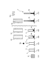
図1に示すように、まず、中実丸棒型の素材M(例えば、直径約16~20mm、長さ約35~50mm)を用意し(ステップS11)、鍛造等により傘部Aを形成すると共に、パンチ等により中空部H(例えば、内径約15~19mm)を形成する(ステップS12)。次に、ステム部S(中空部Hの周辺部分)の外径よりも小さい(例えば、約-0.5~-1.5mm)内径の筒型のダイスD1の内部に上記ステム部Sを挿入して絞り加工を行い、外径及び内径のサイズを縮小させると共に長さを延伸する(ステップS13)。
そして、上記ダイスD1よりも小さい(例えば、約-0.5~-1.5mm)内径の筒型のダイスD2の内部に上記ステム部Sを再度挿入してさらなる絞り加工を行い、外径及び内径のサイズをさらに縮小させると共に長さをさらに延伸する(ステップS14)。以下、このように内径を少しずつ(例えば、約0.5~1.5mmずつ)小さくしたサイズの異なる複数のダイスDxを順次使用して、上記ステム部Sの外径及び内径を規定サイズ(例えば、内径約10~15mm)にまで段階的に縮小すると共に長さを段階的に延伸するように絞り加工を順次行う(ステップS15)。
このように絞り加工を行って、上記ステム部Sを上記規定サイズにまで縮小したら、乾燥不活性ガス雰囲気(例えば、乾燥窒素ガス等)とし、原料ナトリウムから所定のサイズに切り出したブロック状の金属ナトリウムNa(例えば、各辺約8~13mm程度の六面体)を上記中空部Hの上部の開口から内部に投入する(ステップS16)。
このように上記中空部Hの内部に所定のサイズに切り出したブロック状の金属ナトリウムNaを投入したら、引き続き、乾燥不活性ガス雰囲気(例えば、乾燥窒素ガス等)中で、上記ダイスDxよりも小さい(例えば、約-0.5~-1.5mm)内径の筒型のダイスDx+1の内部に上記ステム部Sを改めて挿入して再び絞り加工を行い、外径及び内径のサイズをさらに縮小させると共に長さをさらに延伸する(ステップS17)。このとき、上記中空部Hに投入されたブロック状の金属ナトリウムNaは、上記絞り加工に伴って、当該中空部Hの変形に追従して変形していく。
以下、同様に、内径を少しずつ(例えば、約0.5~1.5mmずつ)小さくしたサイズの異なる複数のダイスDnを順次使用して、上記ステム部Sの外径及び内径を目的とするサイズ(例えば、外径約5~7mm、内径約2~4mm)にまで段階的に縮小すると共に目的とする長さ(例えば、約55~90mm)にまで段階的に延伸するように絞り加工を順次行う(ステップS18)。
このようにして上記ステムSの外径及び内径が目的とするサイズになると共に目的とする長さになったら、金型Dmを使用して上記ステム部Sの端部を塑性加工して閉塞することにより(ステップS19)、ステム部Sの中空部Hに金属ナトリウムNaを封入したエンジンバルブVを得ることができる。
つまり、従来は、目的とするサイズ(例えば、内径約2~4mm)にまで絞り加工を行って成形したステム部Sの中空部Hに金属ナトリウムNaを挿入できるように、棒状に押出成形した固体の金属ナトリウムや、加熱溶融(約120~300℃)した液体の金属ナトリウムを利用するようにしていたが、本実施形態においては、目的とするサイズよりも大きい規定サイズ(例えば、内径約10~15mm)になるまでステム部Sに絞り加工を一旦行ってから、当該ステム部Sの中空部Hにブロック状の固体の金属ナトリウムNa(例えば、各辺約8~13mm程度の六面体)を入れた後に、当該ステム部Sに絞り加工をさらに行って、当該ステム部Sを目的とする上記サイズにまで成形するようにしたのである。
このため、本実施形態においては、原料ナトリウムからブロック状の金属ナトリウムNaを取り扱い易い上記サイズに切り出して上記中空部Hの上部の開口から投入するだけで当該中空部Hの内部に金属ナトリウムNaを入れることができる。
したがって、本実施形態によれば、エンジンバルブVの内部に金属ナトリウムNaを入れることを容易に行うことができる。
〈他の実施形態〉
なお、前述した実施形態においては、先に説明したように、目的とするサイズよりも大きい規定サイズ(例えば、内径約10~15mm)になるまでステム部Sに絞り加工を一旦行ってから、当該ステム部Sの中空部Hにブロック状(例えば、各辺約8~13mm程度の六面体)の固体の金属ナトリウムNaを入れた後に、当該ステム部Sに絞り加工をさらに行って、当該ステム部Sを目的とする上記サイズにまで成形するようにしたが、他の実施形態として、例えば、図2に示すように、素材Mを用意し(ステップS11)、鍛造等により傘部Aを形成すると共に、パンチ等により中空部Hを形成したら(ステップS12)、乾燥不活性ガス雰囲気(例えば、乾燥窒素ガス等)とし、原料ナトリウムから所定のサイズに切り出したブロック状の金属ナトリウムNa(例えば、各辺約13~17mm程度の六面体)を上記中空部Hの上部の開口から内部に投入した後(ステップS23)、ダイスD1の内部に上記ステム部Sを挿入して絞り加工を行い、外径及び内径のサイズを縮小させると共に長さを延伸し(ステップS24)、以下、引き続き、乾燥不活性ガス雰囲気中で、先の説明と同様にして、内径を少しずつ小さくしたサイズの異なる複数のダイスD2,Dn等を順次使用して、上記ステム部Sの外径及び内径を目的とするサイズにまで段階的に縮小すると共に目的とする長さにまで段階的に延伸するように絞り加工を順次行った後(ステップS25,S18)、金型Dmを使用して上記ステム部Sの端部を鍛造して閉塞することにより(ステップS19)、ステム部Sの中空部Hに金属ナトリウムNaを封入したエンジンバルブVを得るようにする、すなわち、前記ステム部Sに絞り加工を行う前に、ブロック状の固体の金属ナトリウムNaを当該ステム部Sの前記中空部Hに入れてから、当該ステム部Sに絞り加工を行うことにより、当該ステム部Sを目的とするサイズに成形することも可能である。
なお、前述した実施形態においては、先に説明したように、目的とするサイズよりも大きい規定サイズ(例えば、内径約10~15mm)になるまでステム部Sに絞り加工を一旦行ってから、当該ステム部Sの中空部Hにブロック状(例えば、各辺約8~13mm程度の六面体)の固体の金属ナトリウムNaを入れた後に、当該ステム部Sに絞り加工をさらに行って、当該ステム部Sを目的とする上記サイズにまで成形するようにしたが、他の実施形態として、例えば、図2に示すように、素材Mを用意し(ステップS11)、鍛造等により傘部Aを形成すると共に、パンチ等により中空部Hを形成したら(ステップS12)、乾燥不活性ガス雰囲気(例えば、乾燥窒素ガス等)とし、原料ナトリウムから所定のサイズに切り出したブロック状の金属ナトリウムNa(例えば、各辺約13~17mm程度の六面体)を上記中空部Hの上部の開口から内部に投入した後(ステップS23)、ダイスD1の内部に上記ステム部Sを挿入して絞り加工を行い、外径及び内径のサイズを縮小させると共に長さを延伸し(ステップS24)、以下、引き続き、乾燥不活性ガス雰囲気中で、先の説明と同様にして、内径を少しずつ小さくしたサイズの異なる複数のダイスD2,Dn等を順次使用して、上記ステム部Sの外径及び内径を目的とするサイズにまで段階的に縮小すると共に目的とする長さにまで段階的に延伸するように絞り加工を順次行った後(ステップS25,S18)、金型Dmを使用して上記ステム部Sの端部を鍛造して閉塞することにより(ステップS19)、ステム部Sの中空部Hに金属ナトリウムNaを封入したエンジンバルブVを得るようにする、すなわち、前記ステム部Sに絞り加工を行う前に、ブロック状の固体の金属ナトリウムNaを当該ステム部Sの前記中空部Hに入れてから、当該ステム部Sに絞り加工を行うことにより、当該ステム部Sを目的とするサイズに成形することも可能である。
しかしながら、前述した実施形態のように、目的とするサイズよりも大きい規定サイズ(例えば、内径約10~15mm)になるまでステム部Sに絞り加工を一旦行ってから、当該ステム部Sの中空部Hにブロック状(例えば、各辺約8~13mm程度の六面体)の固体の金属ナトリウムNaを入れた後に、当該ステム部Sに絞り加工をさらに行って、当該ステム部Sを目的とする上記サイズにまで成形するようにすると、乾燥不活性ガス雰囲気下で行う絞り加工の工程数を必要最小限に抑えることができ、作業効率の低下を抑制することができるので、非常に好ましい。
本発明に係る金属ナトリウム封入エンジンバルブの製造方法は、エンジンバルブの内部に金属ナトリウムを入れることを容易に行うことができるので、産業上、極めて有益に利用することができる。
V エンジンバルブ
A 傘部
S ステム部
H 中空部
D1,D2,Dx,Dx+1,Dn ダイス
Dm 金型
Na 金属ナトリウム
A 傘部
S ステム部
H 中空部
D1,D2,Dx,Dx+1,Dn ダイス
Dm 金型
Na 金属ナトリウム
Claims (3)
- 中空部を有するステム部の外径及び内径のサイズを段階的に縮小させるように当該ステム部に絞り加工を順次行うことにより、当該ステム部を目的とするサイズに成形すると共に、当該ステム部の当該中空部に金属ナトリウムを入れることにより、内部に金属ナトリウムを封入したエンジンバルブを製造する方法において、
ブロック状の固体の金属ナトリウムを前記ステム部の前記中空部に入れてから、当該ステム部に絞り加工を行うことにより、当該ステム部を目的とするサイズに成形する
ことを特徴とする金属ナトリウム封入エンジンバルブの製造方法。 - 請求項1に記載の金属ナトリウム封入エンジンバルブの製造方法において、
前記ステム部の前記中空部の内径が規定サイズになるまで当該ステム部に絞り加工を行ってから、ブロック状の固体の金属ナトリウムを当該ステム部の当該中空部に入れた後に、当該ステム部に絞り加工をさらに行うことにより、当該ステム部を目的とするサイズに成形する
ことを特徴とする金属ナトリウム封入エンジンバルブの製造方法。 - 請求項1に記載の金属ナトリウム封入エンジンバルブの製造方法において、
前記ステム部に絞り加工を行う前に、ブロック状の固体の金属ナトリウムを当該ステム部の前記中空部に入れてから、当該ステム部に絞り加工を行うことにより、当該ステム部を目的とするサイズに成形する
ことを特徴とする金属ナトリウム封入エンジンバルブの製造方法。
Priority Applications (3)
| Application Number | Priority Date | Filing Date | Title |
|---|---|---|---|
| EP10846575.8A EP2541000A4 (en) | 2010-02-26 | 2010-09-09 | METHOD FOR PRODUCING A MOTOR VALVE FILLED WITH SODIUM METAL |
| CN2010800580613A CN102695853A (zh) | 2010-02-26 | 2010-09-09 | 金属钠封入发动机气门的制造方法 |
| US13/504,910 US8713793B2 (en) | 2010-02-26 | 2010-09-09 | Method for producing metallic-sodium-filled engine valve |
Applications Claiming Priority (2)
| Application Number | Priority Date | Filing Date | Title |
|---|---|---|---|
| JP2010041408A JP5297402B2 (ja) | 2010-02-26 | 2010-02-26 | 金属ナトリウム封入エンジンバルブの製造方法 |
| JP2010-041408 | 2010-02-26 |
Publications (1)
| Publication Number | Publication Date |
|---|---|
| WO2011104912A1 true WO2011104912A1 (ja) | 2011-09-01 |
Family
ID=44506351
Family Applications (1)
| Application Number | Title | Priority Date | Filing Date |
|---|---|---|---|
| PCT/JP2010/065465 Ceased WO2011104912A1 (ja) | 2010-02-26 | 2010-09-09 | 金属ナトリウム封入エンジンバルブの製造方法 |
Country Status (5)
| Country | Link |
|---|---|
| US (1) | US8713793B2 (ja) |
| EP (1) | EP2541000A4 (ja) |
| JP (1) | JP5297402B2 (ja) |
| CN (1) | CN102695853A (ja) |
| WO (1) | WO2011104912A1 (ja) |
Cited By (4)
| Publication number | Priority date | Publication date | Assignee | Title |
|---|---|---|---|---|
| WO2015075795A1 (ja) * | 2013-11-21 | 2015-05-28 | 日鍛バルブ株式会社 | 中空ポペットバルブの製造方法 |
| US11300018B2 (en) | 2018-03-20 | 2022-04-12 | Nittan Valve Co., Ltd. | Hollow exhaust poppet valve |
| US11536167B2 (en) | 2018-11-12 | 2022-12-27 | Nittan Valve Co., Ltd. | Method for manufacturing engine poppet valve |
| US11850690B2 (en) | 2020-03-30 | 2023-12-26 | Nittan Corporation | Method for manufacturing engine poppet valve |
Families Citing this family (15)
| Publication number | Priority date | Publication date | Assignee | Title |
|---|---|---|---|---|
| JP4390291B1 (ja) | 2008-09-18 | 2009-12-24 | 株式会社 吉村カンパニー | 中空エンジンバルブの弁傘部の製造方法及び中空エンジンバルブ |
| JP4526097B1 (ja) * | 2009-12-24 | 2010-08-18 | 株式会社 吉村カンパニー | 中空エンジンバルブの弁傘部の製造方法及び中空エンジンバルブの弁傘部のプレス装置及び中空エンジンバルブ |
| US8643452B2 (en) * | 2011-04-07 | 2014-02-04 | Indimet Inc. | Solenoid housing with elongated center pole |
| DE102013203443A1 (de) | 2013-02-28 | 2014-08-28 | Mahle International Gmbh | Metallisches Hohlventil |
| DE102013203441A1 (de) | 2013-02-28 | 2014-08-28 | Bayerische Motoren Werke Aktiengesellschaft | Betriebsverfahren für ein einachsiges Wankstabilisierungssystem eines zweiachsigen, zweispurigen Fahrzeugs |
| WO2014167694A1 (ja) * | 2013-04-11 | 2014-10-16 | 日鍛バルブ株式会社 | 中空ポペットバルブ |
| DE102013213268A1 (de) * | 2013-07-05 | 2015-01-08 | Mahle International Gmbh | Gebautes Hohlventil |
| JP6215156B2 (ja) * | 2014-08-27 | 2017-10-18 | フジホローバルブ株式会社 | 中空エンジンバルブ及びその製造方法 |
| CN104165074A (zh) * | 2014-09-01 | 2014-11-26 | 湖南天雁机械有限责任公司 | 带内螺纹的空心杆发动机气门 |
| CN104801937B (zh) * | 2015-05-11 | 2017-10-31 | 怀集登云汽配股份有限公司 | 一种新型中空充钠气门的成形工艺 |
| US9840948B2 (en) * | 2015-10-28 | 2017-12-12 | Nittan Valve Co., Ltd. | Method for supplying inert gas into poppet valve intermediate and apparatus for supplying inert gas into poppet valve intermediate |
| CN105257359A (zh) * | 2015-10-30 | 2016-01-20 | 重庆奇甫机械有限责任公司 | 具有螺旋叶片的螺旋双腔冲钠气门 |
| DE102018112295A1 (de) * | 2018-05-23 | 2019-11-28 | Federal-Mogul Valvetrain Gmbh | Verfahren zur herstellung eines hohlventils mit optimierter schaftinnengeometrie für verbrennungsmotoren |
| DE102019106222A1 (de) | 2019-03-12 | 2020-09-17 | Federal-Mogul Valvetrain Gmbh | Verfahren zur Herstellung eines Hohlventils für Verbrennungsmotoren |
| CN116261622B (zh) * | 2021-03-16 | 2026-07-10 | 富士乌兹克斯株式会社 | 空心发动机气门及其制造方法 |
Citations (4)
| Publication number | Priority date | Publication date | Assignee | Title |
|---|---|---|---|---|
| JPH0318605A (ja) | 1989-06-14 | 1991-01-28 | Fuji Valve Co Ltd | 中空エンジンバルブヘの金属ナトリウム注入方法及びその装置 |
| JPH07102917A (ja) * | 1993-09-30 | 1995-04-18 | Mitsubishi Heavy Ind Ltd | Na封入中空エンジンバルブの製造方法 |
| WO2007057946A1 (ja) * | 2005-11-15 | 2007-05-24 | Nittan Valve Co., Ltd. | 冷媒入り中空ポペットバルブおよびその製造方法 |
| JP4390291B1 (ja) | 2008-09-18 | 2009-12-24 | 株式会社 吉村カンパニー | 中空エンジンバルブの弁傘部の製造方法及び中空エンジンバルブ |
Family Cites Families (20)
| Publication number | Priority date | Publication date | Assignee | Title |
|---|---|---|---|---|
| US2411734A (en) * | 1942-03-11 | 1946-11-26 | Thompson Prod Inc | Cold worked hollow stem valve |
| US2471937A (en) * | 1944-01-24 | 1949-05-31 | Thompson Prod Inc | Method of making hollow poppet valves |
| US2440461A (en) * | 1944-04-22 | 1948-04-27 | Eaton Mfg Co | Method of sealing the stem of hollow valves |
| US2548092A (en) * | 1949-10-06 | 1951-04-10 | Thompson Prod Inc | Cooled hollow article |
| US2731708A (en) * | 1952-10-31 | 1956-01-24 | Teves Kg Alfred | Process for manufacture of hollow poppet valves especially for internal-combustion engines |
| US3186209A (en) * | 1960-04-14 | 1965-06-01 | Nat Machinery Co | Method of cold forming an elongated hollow article |
| JPS58151306U (ja) * | 1982-04-05 | 1983-10-11 | 日産自動車株式会社 | 内燃機関の吸排気バルブ |
| JPH0656088B2 (ja) * | 1986-10-28 | 1994-07-27 | 富士バルブ株式会社 | 軽量エンジンバルブ及びその製造方法 |
| DE3929534A1 (de) * | 1989-09-06 | 1991-03-28 | Daimler Benz Ag | Verfahren zur herstellung eines ventils |
| JPH03242408A (ja) * | 1990-02-16 | 1991-10-29 | Aisan Ind Co Ltd | 中空エンジンバルブの製造方法 |
| JP2832756B2 (ja) * | 1990-12-28 | 1998-12-09 | フジオーゼックス株式会社 | 中空弁への金属ナトリウムの挿入方法及びその装置 |
| JPH04272413A (ja) * | 1991-02-27 | 1992-09-29 | Mitsubishi Heavy Ind Ltd | 金属ナトリウムの充填方法 |
| US5413073A (en) * | 1993-04-01 | 1995-05-09 | Eaton Corporation | Ultra light engine valve |
| JPH07119421A (ja) | 1993-10-25 | 1995-05-09 | Mitsubishi Heavy Ind Ltd | Na封入中空エンジンバルブの製造方法 |
| JPH09184404A (ja) * | 1995-12-28 | 1997-07-15 | Fuji Oozx Inc | 内燃機関用中空弁 |
| JPH10219377A (ja) * | 1997-02-07 | 1998-08-18 | Daido Steel Co Ltd | ディーゼルエンジンの高耐食性吸排気バルブ用合金及び吸排気バルブの製造方法 |
| EP0911493A3 (en) * | 1997-10-21 | 2000-04-12 | Eaton Corporation | Improved tip structures for an ultra light engine valve |
| AT2881U1 (de) * | 1998-06-08 | 1999-06-25 | Plansee Ag | Verfahren zur herstellung eines tellerventiles aus gamma-tial-basislegierungen |
| JP2006088197A (ja) * | 2004-09-24 | 2006-04-06 | Aisan Ind Co Ltd | 拡大頭部を有する軸状製品の製造方法及びエンジンバルブの製造方法並びに拡大頭部を有する軸状製品の製造に用いる鍛造型 |
| CN101169054A (zh) * | 2007-10-16 | 2008-04-30 | 韩鸿滨 | 轻质气门 |
-
2010
- 2010-02-26 JP JP2010041408A patent/JP5297402B2/ja not_active Expired - Fee Related
- 2010-09-09 WO PCT/JP2010/065465 patent/WO2011104912A1/ja not_active Ceased
- 2010-09-09 US US13/504,910 patent/US8713793B2/en not_active Expired - Fee Related
- 2010-09-09 CN CN2010800580613A patent/CN102695853A/zh active Pending
- 2010-09-09 EP EP10846575.8A patent/EP2541000A4/en not_active Withdrawn
Patent Citations (4)
| Publication number | Priority date | Publication date | Assignee | Title |
|---|---|---|---|---|
| JPH0318605A (ja) | 1989-06-14 | 1991-01-28 | Fuji Valve Co Ltd | 中空エンジンバルブヘの金属ナトリウム注入方法及びその装置 |
| JPH07102917A (ja) * | 1993-09-30 | 1995-04-18 | Mitsubishi Heavy Ind Ltd | Na封入中空エンジンバルブの製造方法 |
| WO2007057946A1 (ja) * | 2005-11-15 | 2007-05-24 | Nittan Valve Co., Ltd. | 冷媒入り中空ポペットバルブおよびその製造方法 |
| JP4390291B1 (ja) | 2008-09-18 | 2009-12-24 | 株式会社 吉村カンパニー | 中空エンジンバルブの弁傘部の製造方法及び中空エンジンバルブ |
Non-Patent Citations (1)
| Title |
|---|
| See also references of EP2541000A4 * |
Cited By (6)
| Publication number | Priority date | Publication date | Assignee | Title |
|---|---|---|---|---|
| WO2015075795A1 (ja) * | 2013-11-21 | 2015-05-28 | 日鍛バルブ株式会社 | 中空ポペットバルブの製造方法 |
| JPWO2015075795A1 (ja) * | 2013-11-21 | 2017-03-16 | 日鍛バルブ株式会社 | 中空ポペットバルブの製造方法 |
| US9751164B2 (en) | 2013-11-21 | 2017-09-05 | Nittan Valve Co., Ltd. | Method of manufacturing a hollow poppet valve |
| US11300018B2 (en) | 2018-03-20 | 2022-04-12 | Nittan Valve Co., Ltd. | Hollow exhaust poppet valve |
| US11536167B2 (en) | 2018-11-12 | 2022-12-27 | Nittan Valve Co., Ltd. | Method for manufacturing engine poppet valve |
| US11850690B2 (en) | 2020-03-30 | 2023-12-26 | Nittan Corporation | Method for manufacturing engine poppet valve |
Also Published As
| Publication number | Publication date |
|---|---|
| JP2011179326A (ja) | 2011-09-15 |
| EP2541000A1 (en) | 2013-01-02 |
| JP5297402B2 (ja) | 2013-09-25 |
| CN102695853A (zh) | 2012-09-26 |
| EP2541000A4 (en) | 2014-01-29 |
| US20120246934A1 (en) | 2012-10-04 |
| US8713793B2 (en) | 2014-05-06 |
Similar Documents
| Publication | Publication Date | Title |
|---|---|---|
| JP5297402B2 (ja) | 金属ナトリウム封入エンジンバルブの製造方法 | |
| KR101346899B1 (ko) | 금속 나트륨 봉입 엔진 밸브의 제조 방법 | |
| US10596623B2 (en) | Low-pressure casting secondary pressure process for aluminum wheel | |
| US8881391B2 (en) | Method for producing hollow engine valve | |
| CN103403305B (zh) | 中空发动机气门的制造方法 | |
| US20120304464A1 (en) | Method for manufacturing hollow engine valve | |
| CN106756300B (zh) | 一种无缸套铝合金缸体真空压铸方法 | |
| WO2011104923A1 (ja) | 金属ナトリウム封入エンジンバルブの製造方法 | |
| JP5473771B2 (ja) | 金属ナトリウム封入エンジンバルブの製造方法 | |
| WO2009050382A3 (fr) | Procede de fabrication de pieces forgees creuses et pieces ainsi obtenues | |
| GB2538239A (en) | Method for producing a poppet valve, in particular a hollow head valve | |
| JPH02299738A (ja) | 圧力容器と圧力容器製造方法 | |
| RU2688989C1 (ru) | Способ изготовления бесшовного стального баллона высокого давления со второй внутренней горловиной | |
| CN214640007U (zh) | 一种厚壁管毛坯套模装置 | |
| RU2327539C2 (ru) | СПОСОБ ИЗГОТОВЛЕНИЯ ИЗ ТОНКОЛИСТОВЫХ МАТЕРИАЛОВ ТОЛЩИНОЙ ОТ 0,2 мм И МЕНЕЕ СТУПЕНЧАТЫХ ОСЕСИММЕТРИЧНЫХ ОБОЛОЧЕК С ЦЕНТРАЛЬНЫМ ВЫСТУПОМ, ОТНОШЕНИЕ ВЫСОТЫ КОТОРОГО К ЕГО ДИАМЕТРУ РАВНО ИЛИ ПРЕВЫШАЕТ 0,5 | |
| RU2242315C2 (ru) | Способ изготовления полых сферических деталей | |
| CN109332630A (zh) | 用于adc12合金半固态坯料的制备方法 | |
| CN109202031A (zh) | 预变形车用合金半固态坯料的制备方法 | |
| CN208772363U (zh) | 双定径带封闭式束杆模 | |
| JP2014140874A (ja) | 中間成形品製造用金型、中間成形品の製造方法、エンジンバルブの製造方法、中間成形品及びエンジンバルブ | |
| RU2001128693A (ru) | Способ изготовления поковок с отростками | |
| RU2285579C1 (ru) | Устройство для отливки стальных слитков | |
| CN108342554A (zh) | 一种022Cr19Ni10N钢的静压开坯方法 | |
| JP2012125790A (ja) | 中空エンジンバルブの製造方法 | |
| RU2021101964A (ru) | Непрерывный способ изготовления капилляров, выполненных из цветных сплавов |
Legal Events
| Date | Code | Title | Description |
|---|---|---|---|
| 121 | Ep: the epo has been informed by wipo that ep was designated in this application |
Ref document number: 10846575 Country of ref document: EP Kind code of ref document: A1 |
|
| WWE | Wipo information: entry into national phase |
Ref document number: 2010846575 Country of ref document: EP |
|
| WWE | Wipo information: entry into national phase |
Ref document number: 1036/MUMNP/2012 Country of ref document: IN |
|
| WWE | Wipo information: entry into national phase |
Ref document number: 13504910 Country of ref document: US |
|
| NENP | Non-entry into the national phase |
Ref country code: DE |