WO2011108704A1 - Aimant de terre rare fritté et moteur - Google Patents
Aimant de terre rare fritté et moteur Download PDFInfo
- Publication number
- WO2011108704A1 WO2011108704A1 PCT/JP2011/055067 JP2011055067W WO2011108704A1 WO 2011108704 A1 WO2011108704 A1 WO 2011108704A1 JP 2011055067 W JP2011055067 W JP 2011055067W WO 2011108704 A1 WO2011108704 A1 WO 2011108704A1
- Authority
- WO
- WIPO (PCT)
- Prior art keywords
- rare earth
- sintered magnet
- earth sintered
- magnet body
- slurry
- Prior art date
- Legal status (The legal status is an assumption and is not a legal conclusion. Google has not performed a legal analysis and makes no representation as to the accuracy of the status listed.)
- Ceased
Links
Images





Classifications
-
- H—ELECTRICITY
- H02—GENERATION; CONVERSION OR DISTRIBUTION OF ELECTRIC POWER
- H02K—DYNAMO-ELECTRIC MACHINES
- H02K1/00—Details of the magnetic circuit
- H02K1/02—Details of the magnetic circuit characterised by the magnetic material
-
- B—PERFORMING OPERATIONS; TRANSPORTING
- B22—CASTING; POWDER METALLURGY
- B22F—WORKING METALLIC POWDER; MANUFACTURE OF ARTICLES FROM METALLIC POWDER; MAKING METALLIC POWDER; APPARATUS OR DEVICES SPECIALLY ADAPTED FOR METALLIC POWDER
- B22F3/00—Manufacture of workpieces or articles from metallic powder characterised by the manner of compacting or sintering; Apparatus specially adapted therefor ; Presses and furnaces
- B22F3/24—After-treatment of workpieces or articles
-
- B—PERFORMING OPERATIONS; TRANSPORTING
- B22—CASTING; POWDER METALLURGY
- B22F—WORKING METALLIC POWDER; MANUFACTURE OF ARTICLES FROM METALLIC POWDER; MAKING METALLIC POWDER; APPARATUS OR DEVICES SPECIALLY ADAPTED FOR METALLIC POWDER
- B22F9/00—Making metallic powder or suspensions thereof
- B22F9/02—Making metallic powder or suspensions thereof using physical processes
- B22F9/023—Hydrogen absorption
-
- B—PERFORMING OPERATIONS; TRANSPORTING
- B22—CASTING; POWDER METALLURGY
- B22F—WORKING METALLIC POWDER; MANUFACTURE OF ARTICLES FROM METALLIC POWDER; MAKING METALLIC POWDER; APPARATUS OR DEVICES SPECIALLY ADAPTED FOR METALLIC POWDER
- B22F9/00—Making metallic powder or suspensions thereof
- B22F9/02—Making metallic powder or suspensions thereof using physical processes
- B22F9/04—Making metallic powder or suspensions thereof using physical processes starting from solid material, e.g. by crushing, grinding or milling
-
- C—CHEMISTRY; METALLURGY
- C22—METALLURGY; FERROUS OR NON-FERROUS ALLOYS; TREATMENT OF ALLOYS OR NON-FERROUS METALS
- C22C—ALLOYS
- C22C33/00—Making ferrous alloys
- C22C33/02—Making ferrous alloys by powder metallurgy
- C22C33/0257—Making ferrous alloys by powder metallurgy characterised by the range of the alloying elements
- C22C33/0278—Making ferrous alloys by powder metallurgy characterised by the range of the alloying elements with at least one alloying element having a minimum content above 5%
-
- C—CHEMISTRY; METALLURGY
- C22—METALLURGY; FERROUS OR NON-FERROUS ALLOYS; TREATMENT OF ALLOYS OR NON-FERROUS METALS
- C22C—ALLOYS
- C22C38/00—Ferrous alloys, e.g. steel alloys
- C22C38/002—Ferrous alloys, e.g. steel alloys containing In, Mg, or other elements not provided for in one single group C22C38/001 - C22C38/60
-
- C—CHEMISTRY; METALLURGY
- C22—METALLURGY; FERROUS OR NON-FERROUS ALLOYS; TREATMENT OF ALLOYS OR NON-FERROUS METALS
- C22C—ALLOYS
- C22C38/00—Ferrous alloys, e.g. steel alloys
- C22C38/005—Ferrous alloys, e.g. steel alloys containing rare earths, i.e. Sc, Y, Lanthanides
-
- C—CHEMISTRY; METALLURGY
- C22—METALLURGY; FERROUS OR NON-FERROUS ALLOYS; TREATMENT OF ALLOYS OR NON-FERROUS METALS
- C22C—ALLOYS
- C22C38/00—Ferrous alloys, e.g. steel alloys
- C22C38/06—Ferrous alloys, e.g. steel alloys containing aluminium
-
- C—CHEMISTRY; METALLURGY
- C22—METALLURGY; FERROUS OR NON-FERROUS ALLOYS; TREATMENT OF ALLOYS OR NON-FERROUS METALS
- C22C—ALLOYS
- C22C38/00—Ferrous alloys, e.g. steel alloys
- C22C38/10—Ferrous alloys, e.g. steel alloys containing cobalt
-
- C—CHEMISTRY; METALLURGY
- C22—METALLURGY; FERROUS OR NON-FERROUS ALLOYS; TREATMENT OF ALLOYS OR NON-FERROUS METALS
- C22C—ALLOYS
- C22C38/00—Ferrous alloys, e.g. steel alloys
- C22C38/16—Ferrous alloys, e.g. steel alloys containing copper
-
- H—ELECTRICITY
- H01—ELECTRIC ELEMENTS
- H01F—MAGNETS; INDUCTANCES; TRANSFORMERS; SELECTION OF MATERIALS FOR THEIR MAGNETIC PROPERTIES
- H01F1/00—Magnets or magnetic bodies characterised by the magnetic materials therefor; Selection of materials for their magnetic properties
- H01F1/01—Magnets or magnetic bodies characterised by the magnetic materials therefor; Selection of materials for their magnetic properties of inorganic materials
- H01F1/03—Magnets or magnetic bodies characterised by the magnetic materials therefor; Selection of materials for their magnetic properties of inorganic materials characterised by their coercivity
- H01F1/032—Magnets or magnetic bodies characterised by the magnetic materials therefor; Selection of materials for their magnetic properties of inorganic materials characterised by their coercivity of hard-magnetic materials
- H01F1/04—Magnets or magnetic bodies characterised by the magnetic materials therefor; Selection of materials for their magnetic properties of inorganic materials characterised by their coercivity of hard-magnetic materials metals or alloys
- H01F1/047—Alloys characterised by their composition
- H01F1/053—Alloys characterised by their composition containing rare earth metals
- H01F1/055—Alloys characterised by their composition containing rare earth metals and magnetic transition metals, e.g. SmCo5
- H01F1/057—Alloys characterised by their composition containing rare earth metals and magnetic transition metals, e.g. SmCo5 and IIIa elements, e.g. Nd2Fe14B
- H01F1/0571—Alloys characterised by their composition containing rare earth metals and magnetic transition metals, e.g. SmCo5 and IIIa elements, e.g. Nd2Fe14B in the form of particles, e.g. rapid quenched powders or ribbon flakes
- H01F1/0575—Alloys characterised by their composition containing rare earth metals and magnetic transition metals, e.g. SmCo5 and IIIa elements, e.g. Nd2Fe14B in the form of particles, e.g. rapid quenched powders or ribbon flakes pressed, sintered or bonded together
- H01F1/0577—Alloys characterised by their composition containing rare earth metals and magnetic transition metals, e.g. SmCo5 and IIIa elements, e.g. Nd2Fe14B in the form of particles, e.g. rapid quenched powders or ribbon flakes pressed, sintered or bonded together sintered
-
- H—ELECTRICITY
- H01—ELECTRIC ELEMENTS
- H01F—MAGNETS; INDUCTANCES; TRANSFORMERS; SELECTION OF MATERIALS FOR THEIR MAGNETIC PROPERTIES
- H01F41/00—Apparatus or processes specially adapted for manufacturing or assembling magnets, inductances or transformers; Apparatus or processes specially adapted for manufacturing materials characterised by their magnetic properties
- H01F41/02—Apparatus or processes specially adapted for manufacturing or assembling magnets, inductances or transformers; Apparatus or processes specially adapted for manufacturing materials characterised by their magnetic properties for manufacturing cores, coils, or magnets
- H01F41/0253—Apparatus or processes specially adapted for manufacturing or assembling magnets, inductances or transformers; Apparatus or processes specially adapted for manufacturing materials characterised by their magnetic properties for manufacturing cores, coils, or magnets for manufacturing permanent magnets
- H01F41/0293—Apparatus or processes specially adapted for manufacturing or assembling magnets, inductances or transformers; Apparatus or processes specially adapted for manufacturing materials characterised by their magnetic properties for manufacturing cores, coils, or magnets for manufacturing permanent magnets diffusion of rare earth elements, e.g. Tb, Dy or Ho, into permanent magnets
-
- H—ELECTRICITY
- H01—ELECTRIC ELEMENTS
- H01F—MAGNETS; INDUCTANCES; TRANSFORMERS; SELECTION OF MATERIALS FOR THEIR MAGNETIC PROPERTIES
- H01F7/00—Magnets
- H01F7/02—Permanent magnets [PM]
-
- H—ELECTRICITY
- H02—GENERATION; CONVERSION OR DISTRIBUTION OF ELECTRIC POWER
- H02K—DYNAMO-ELECTRIC MACHINES
- H02K15/00—Processes or apparatus specially adapted for manufacturing, assembling, maintaining or repairing of dynamo-electric machines
- H02K15/02—Processes or apparatus specially adapted for manufacturing, assembling, maintaining or repairing of dynamo-electric machines of stator or rotor bodies
- H02K15/03—Processes or apparatus specially adapted for manufacturing, assembling, maintaining or repairing of dynamo-electric machines of stator or rotor bodies having permanent magnets
-
- B—PERFORMING OPERATIONS; TRANSPORTING
- B22—CASTING; POWDER METALLURGY
- B22F—WORKING METALLIC POWDER; MANUFACTURE OF ARTICLES FROM METALLIC POWDER; MAKING METALLIC POWDER; APPARATUS OR DEVICES SPECIALLY ADAPTED FOR METALLIC POWDER
- B22F2999/00—Aspects linked to processes or compositions used in powder metallurgy
Definitions
- the present invention relates to a rare earth sintered magnet and a motor obtained by attaching a rare earth compound to a rare earth sintered magnet body and heat-treating the rare earth compound.
- a rare earth sintered magnet having a composition of R—Fe—B (R is a rare earth element) is a magnet having excellent magnetic properties.
- R is a rare earth element
- a method for producing such a rare earth magnet there is a method in which a slurry containing a rare earth is applied (attached) to a sintered body and then subjected to heat treatment.
- a slurry containing a rare earth is applied (attached) to a sintered body and then subjected to heat treatment.
- Patent Document 1 in a state where a powder containing rare earth elements including Y and Sc is present on the surface of the sintered magnet body, the sintered magnet body and the powder are below the sintering temperature of the sintered magnet body.
- Patent Document 1 describes a method of putting a sintered magnet body into a slurry in which the powder is dispersed in water or an organic solvent as a method for attaching a powder containing a rare earth element to the sintered magnet body.
- the thickness of the applied slurry varies depending on the position of the surface, and unevenness may occur. If there is unevenness in the adhering slurry (the amount of adhering rare earth compound) in this way, then in the magnet manufactured by heat treatment, the surface magnetic flux will vary, and the magnetic characteristics such as residual magnetic flux density Br will be uneven. There was a problem of doing.
- the present invention has been made in view of the above, and an object thereof is to provide a rare earth sintered magnet in which unevenness of magnetic properties is suppressed.
- the present invention provides (R1, R2) 2 T 14 B (R1 is at least one rare earth element excluding Dy and Tb, and R2 represents Dy and Tb.
- R1 is at least one rare earth element excluding Dy and Tb
- R2 represents Dy and Tb.
- a rare earth sintered magnet having a rare earth sintered magnet body including crystal grains of a rare earth element including at least one or both, wherein T represents one or more transition metal elements including Fe or Fe and Co.
- the ratio of R2 to the sum of R1 and R2 contained in the crystal grain boundary surrounding the crystal grains in the rare earth sintered magnet body is greater than the ratio of R2 to the sum of R1 and R2 in the crystal grains.
- the concentration of R2 increases from the center of the rare earth sintered magnet body toward the surface of the rare earth sintered magnet body, and the variation in the residual magnetic flux density Br on the surface of the rare earth sintered magnet body is less than 3.0%. It is characterized by Rare earth sintered magnet.
- R1, R2 The rare earth sintered magnet body in a state in which a slurry containing a rare earth compound of R2 is present on the surface of the rare earth sintered magnet body in the rare earth sintered magnet body containing 2 T 14 B crystal grains.
- the slurry is then heat treated to absorb the R2 rare earth compound contained in the slurry.
- the R2 rare earth compound contained in the slurry existing on the surface of the sintered magnet body is taken into the rare earth sintered magnet body through the crystal grain boundaries (grain boundaries of crystal grains), It diffuses inside the crystal grains.
- the ratio of R2 to the sum of R1 and R2 included in the crystal grain boundary surrounding the (R1, R2) 2 T 14 B crystal grains in the rare earth sintered magnet body is such that R1 in the crystal grains And R2 with respect to the sum of R2 and R2. Since the R-rich layer at the grain boundary is liquefied by heating, the diffusion rate of R2 in the crystal grain boundary is considered to be faster than the diffusion rate from the grain boundary to the inside of the crystal grain. Also, heat treatment is performed at a temperature below the sintering temperature of the rare earth sintered magnet body, so that the R2 rare earth compound diffuses into the crystal grain boundaries of the rare earth sintered magnet body and diffuses into the crystal grains. do not do.
- R2 diffuses in the vicinity of the grain boundary of the rare earth sintered magnet body.
- R2 rare earth compound is applied to the surface of the rare earth sintered magnet body and supplied, R2 is distributed more on the surface side of the rare earth sintered magnet body than inside the rare earth sintered magnet body. Therefore, the concentration of R2 is distributed so as to increase from the center of the rare earth sintered magnet body toward the surface of the rare earth sintered magnet body.
- the R2 rare earth compound is taken from the surface of the rare earth sintered magnet body through the grain boundaries into the rare earth sintered magnet body and diffused from the grain boundaries to the inside of each crystal grain, and R2 is introduced in the vicinity of the grain boundaries of the crystal grains. Spread.
- the ratio of R2 to the sum of R1 and R2 contained in the crystal grain boundary in the rare earth sintered magnet body is such that R2 is relative to the sum of R1 and R2 in the crystal grain. Higher than the rate.
- the rare earth sintered magnet of the present invention can increase the coercive force HcJ of the magnet with almost no decrease in the residual magnetic flux density Br.
- the variation of the residual magnetic flux density Br on the surface of the rare earth sintered magnet body is less than 3.0%.
- the rare earth sintered magnet after the heat treatment can suppress variations in the magnetic flux on the surface thereof, and can suppress unevenness in magnetic characteristics such as residual magnetic flux density Br.
- the rare earth sintered magnet of the present invention when used as a permanent magnet for a motor, the cogging torque of the motor can be reduced.
- the variation in coercive force HcJ on the surface of the rare earth sintered magnet body is preferably less than 18.0%.
- the demagnetization temperature at which the rare earth sintered magnet begins to demagnetize can be increased. For this reason, when a rare earth sintered magnet is used as a permanent magnet for a motor, the heat resistance of the permanent magnet can be improved.
- the rare earth sintered magnet body has a plurality of surfaces, and the surface of the plurality of surfaces of the rare earth sintered magnet body that minimizes the variation in the residual magnetic flux density Br is the rare earth sintered magnet.
- a plane perpendicular to the body orientation direction is preferred.
- the surface of the rare earth sintered magnet body in which the variation of the residual magnetic flux density Br is smaller than the other surfaces of the rare earth sintered magnet body is a surface perpendicular to the orientation direction of the rare earth sintered magnet body. The variation of is small. For this reason, since the rare earth sintered magnet of the present invention can improve motor performance such as torque characteristics of the motor, it can be suitably used as a permanent magnet for a motor.
- the present invention relates to (R1, R2) 2 T 14 B (R1 is at least one rare earth element excluding Dy and Tb, R2 is a rare earth element containing at least one of or both of Dy and Tb, Represents a one or more transition metal elements including Fe or Fe and Co) and rotates a rare earth sintered magnet body including a crystal grain of R2 and applies a slurry containing a R2 rare earth compound to the rare earth sintered magnet body, Crystal grains surrounding the crystal grains in the rare earth sintered magnet body obtained by heat-treating the rare earth sintered magnet body with the slurry dried while rotating the rare earth sintered magnet body.
- the ratio of R2 to the sum of R1 and R2 contained in the boundary is higher than the ratio of R2 to the sum of R1 and R2 in the crystal grains, and the concentration of R2 is rare earth sintered magnet from the center of the rare earth sintered magnet body.
- the rare earth sintered magnet is characterized in that the variation in residual magnetic flux density on the surface of the rare earth sintered magnet body is less than 3.0%.
- the slurry By supplying the slurry containing the R2 rare earth compound toward the rare earth sintered magnet body while rotating the rare earth sintered magnet body, the slurry can be uniformly applied to the entire rare earth sintered magnet body.
- the rare earth sintered magnet of the present invention takes in the R2 rare earth compound from the surface of the rare earth sintered magnet body into the rare earth sintered magnet body through the grain boundaries, and from the grain boundaries, While diffusing inside, R2 is diffused in the vicinity of the grain boundaries of the crystal grains.
- the rare earth sintered magnet of the present invention can increase the coercive force HcJ of the magnet with almost no decrease in the residual magnetic flux density Br.
- the variation of the residual magnetic flux density Br on the surface of the rare earth sintered magnet body is set to less than 3.0%.
- the rare earth sintered magnet manufactured by heat treatment as described above can suppress variations in magnetic flux on the surface thereof, and can suppress uneven magnetic properties such as residual magnetic flux density Br. For this reason, when the rare earth sintered magnet of the present invention is used as a permanent magnet for a motor, the cogging torque of the motor can be reduced.
- the slurry applied to the rare earth sintered magnet body is dried, so that the unevenness of the thickness of the applied slurry can be more reliably suppressed.
- the slurry is preferably sprayed onto the rare earth sintered magnet body by spraying and applied to the rare earth sintered magnet body.
- the slurry can be more uniformly applied to the entire area in the axial direction of the rare earth sintered magnet body.
- the present invention it is preferable to immerse the rare earth sintered magnet body in a region where the slurry is stored and apply the slurry to the rare earth sintered magnet body.
- the slurry can be easily and uniformly applied to the entire area of the rare earth sintered magnet body.
- the slurry is preferably applied to the rare earth sintered magnet body as a plurality of slurry streams.
- the slurry can be uniformly applied to the entire area of the rare earth sintered magnet body in the axial direction.
- the slurry is applied to the rare earth sintered magnet body by dropping from the upper position in the vertical direction of the arrangement position of the rare earth sintered magnet body. Since the slurry is applied to the rare earth sintered magnet body by dropping from the vertical direction above the position where the rare earth sintered magnet body is disposed, the slurry is simply and uniformly applied to the entire area of the rare earth sintered magnet body in the axial direction. be able to.
- the motor of the present invention comprises the rare earth sintered magnet of the present invention, and is provided with a stator having a plurality of coils arranged in the circumferential direction, rotatably provided in the stator, and on the outer circumferential surface. And a rotor having a rotor core on which the rare earth sintered magnet described in any one of the above is provided at a predetermined interval. Since the motor of the present invention uses a rare earth sintered magnet with suppressed magnetic property unevenness as a permanent magnet, cogging torque, torque ripple, and the like can be reduced, and motor performance can be improved.
- the present invention it is possible to provide a rare earth sintered magnet in which unevenness of magnetic properties is suppressed. Moreover, motor performance can be improved by using the said rare earth sintered magnet for a motor.
- FIG. 1 is a flowchart showing a method for manufacturing a rare earth sintered magnet according to an embodiment of the present invention.
- FIG. 2 is a diagram schematically illustrating the configuration of the magnet manufacturing apparatus.
- FIG. 3 is a flowchart showing a method of manufacturing a rare earth sintered magnet body used for manufacturing the rare earth sintered magnet according to the embodiment of the present invention.
- FIG. 4 is a schematic diagram schematically showing the configuration of the coating mechanism.
- FIG. 5 is a schematic diagram schematically showing the configuration of the coating means.
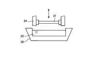
- FIG. 6 is an explanatory view simply showing another configuration in which slurry is applied to the rare earth sintered magnet body.
- FIG. 7 is an explanatory view simply showing another configuration in which slurry is applied to a rare earth sintered magnet body.
- FIG. 6 is an explanatory view simply showing another configuration in which slurry is applied to the rare earth sintered magnet body.
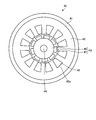
- FIG. 8 is a longitudinal sectional view schematically showing the configuration of an embodiment of the motor.
- FIG. 9 is a diagram schematically showing a cross section in the AA direction in FIG.
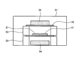
- FIG. 10 is a view showing an example of a processing container used for vapor-depositing DyH 2 on the surface of a rare earth sintered magnet body.
- FIG. 11 is an explanatory view showing each region of the sintered body.
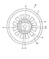
- FIG. 12 is a cross-sectional view schematically showing an example of the configuration of the motor used in the magnetic field analysis simulation.
- the rare earth sintered magnet according to this embodiment is (R1, R2) 2 T 14 B (R1 is at least one kind of rare earth element excluding Dy and Tb, and R2 is at least one or both of Dy and Tb. It is a rare earth sintered magnet having a rare earth sintered magnet body including crystal grains of a rare earth element including T and T represents one or more transition metal elements including Fe and Co. Further, in the rare earth sintered magnet according to the present embodiment, the ratio of R2 to the sum of R1 and R2 included in the crystal grain boundary surrounding the crystal grains in the rare earth sintered magnet body is R1 in the crystal grains. It is higher than the ratio of R2 with respect to the sum of R2, and the concentration of R2 is made higher from the rare earth sintered magnet body central portion toward the rare earth sintered magnet body surface.
- the composition of crystal grains contained in the main phase of the RTB-based rare earth sintered magnet is represented by a composition formula of (R1, R2) 2 T 14 B.
- This main phase has a crystal structure made of (R1, R2) 2 T 14 B type tetragonal crystals. Therefore, R representing the composition of the main phase of the RTB-based rare earth sintered magnet is a general term for R1 and R2.
- R represents at least one rare earth element
- R1 represents at least one rare earth element excluding Dy and Tb
- R2 represents a rare earth element including at least one or both of Dy and Tb
- T represents One or more transition metal elements including Fe or Fe and Co are represented.
- the rare earth sintered magnet includes both a magnet product obtained by processing the magnet and magnetized and the magnet not magnetized.
- the crystal grain boundary may include a rare earth-rich phase with a high mixing ratio of rare earth elements and a boron-rich phase with a high mixing ratio of boron (B) atoms.
- the crystal grain size is usually about 1 ⁇ m to 30 ⁇ m.
- the rare earth sintered magnet according to the present embodiment is obtained by subjecting the rare earth sintered magnet body and the slurry to heat treatment in a state in which the slurry containing the R2 rare earth compound is present on the surface of the rare earth sintered magnet body.
- the rare earth sintered magnet body in which the R2 rare earth compound is absorbed is used.
- the R2 rare earth compound contained in the slurry present on the surface of the sintered magnet body is taken into the rare earth sintered magnet body through the grain boundaries, and is mainly introduced from the grain boundaries. It diffuses inside each crystal grain of the phase.
- the diffusion rate of R2 in the grain boundary is considered to be faster than the diffusion rate from the grain boundary to the inside of the crystal grain.
- R2 diffuses in the vicinity of the grain boundaries of the rare earth sintered magnet body. .
- the ratio of R2 to the sum of R1 and R2 included in the crystal grain boundary is higher than the ratio of R2 to the sum of R1 and R2 in the crystal grain.
- the R2 rare earth compound is applied to the surface of the rare earth sintered magnet body and supplied to the inside of the rare earth sintered magnet body, there is more R2 on the surface side of the rare earth sintered magnet body than inside the rare earth sintered magnet body. Distributed. Therefore, the concentration of R2 increases from the center of the rare earth sintered magnet body toward the surface of the rare earth sintered magnet body.
- the R2 rare earth compound is taken from the surface of the rare earth sintered magnet body into the rare earth sintered magnet body through the crystal grain boundary, and is diffused from the crystal boundary to the inside of each crystal grain. R2 is diffused in the vicinity of the grain boundaries of the crystal grains. For this reason, the rare earth sintered magnet according to the present embodiment can improve the coercive force HcJ with almost no decrease in the residual magnetic flux density Br as compared with the case where R2 is added from the alloy.
- the rare earth compound of R2 contained in the slurry When the rare earth compound of R2 contained in the slurry is absorbed by the rare earth sintered magnet body, heat treatment is performed in a vacuum or an inert gas atmosphere such as Ar (argon) or helium (He). In an atmosphere where the processing chamber is close to atmospheric pressure, the R2 rare earth compound contained in the slurry is less likely to be supplied into the sintered magnet body.
- the R2 rare earth compound of the sintered magnet body is reduced by reducing the pressure in the processing chamber to a vacuum or an inert gas atmosphere and a pressure lower than the atmosphere. It becomes easy to be supplied from the surface to the inside. Thereby, the coercive force HcJ of the rare earth sintered magnet can be improved.
- the heat treatment temperature at the time of heat treatment is a temperature below the sintering temperature of the rare earth sintered magnet body. This is because if the heat treatment is performed at a temperature higher than the sintering temperature of the rare earth sintered magnet body, the structure of the rare earth sintered magnet may be transformed. Further, the R2 rare earth compound diffuses not only to the crystal grain boundary of the rare earth sintered magnet body but also to the inside of the crystal grain, and there is a possibility that the residual magnetic flux density Br on the surface of the rare earth sintered magnet body may be reduced.
- the variation in the residual magnetic flux density Br in the plane perpendicular to the orientation direction of the rare earth sintered magnet body is less than 3.0%, preferably 2.5% or less, more preferably 2.0%. It is.
- the variation in the residual magnetic flux density Br on the surface perpendicular to the orientation direction of the rare earth sintered magnet body is 3.0% or more, the rare earth sintered magnet manufactured by heat treatment has a large variation in the magnetic flux on the surface.
- the cogging torque cannot be reduced.
- the variation in the residual magnetic flux density Br is extracted as a sample piece from a plurality of locations on the surface of the rare earth sintered magnet body, and the residual magnetic flux density Br of each sample piece is measured.
- the residual magnetic flux density Br is measured by attaching a sample piece taken out from the surface of the rare earth sintered magnet body to an acrylic rod and measuring it using a vibrating sample magnetometer (VSM: Vibrating Sample Magnetometer). Is measured.
- VSM Vibrating Sample Magnetometer
- the thickness of the slurry to be applied varies depending on the position of the surface, resulting in unevenness.
- the variation in the residual magnetic flux density Br on the surface perpendicular to the orientation direction of the manufactured magnet was also large.
- the slurry containing the R2 rare earth compound is applied to the surface of the rare earth sintered magnet body while rotating the rare earth sintered magnet body. Variation in the thickness of the slurry applied to the surface can be reduced.
- vertical to the orientation direction of a rare earth sintered magnet body can be made into the said range.
- the nonuniformity of the magnetic characteristics of the magnet can be further suppressed.
- the rare earth sintered magnet according to the present embodiment is used as a permanent magnet of a motor, for example, the cogging torque of the motor can be reduced.
- the diffusion amount of the R2 rare earth compound in the rare earth sintered magnet body is different in the planar direction of the rare earth sintered magnet body. Since they are different, the coercive force HcJ on the surface of the rare earth sintered magnet body is different.
- the variation in the thickness of the slurry applied to the surface of the rare earth sintered magnet body the variation in the diffusion amount of the R2 rare earth compound in the rare earth sintered magnet body in the plane direction of the rare earth sintered magnet body is reduced. .
- variation in the coercive force HcJ in the surface of a rare earth sintered magnet body can be reduced.
- the variation of the coercive force HcJ on the surface of the rare earth sintered magnet body is preferably less than 18.0%, more preferably 15% or less, and even more preferably 10% or less.
- the variation of the coercive force HcJ on the surface of the rare earth sintered magnet body is 18.0% or more, when the rare earth sintered magnet manufactured by heat treatment is used as a magnet for a motor, sufficient heat resistance is obtained. It is because it cannot have.
- the demagnetization temperature at which the rare earth sintered magnet begins to demagnetize can be increased.
- the heat resistance of a permanent magnet can be improved.
- the variation in the coercive force HcJ is extracted as a sample piece from a plurality of locations on the surface of the rare earth sintered magnet body, and the coercive force HcJ of each sample piece is measured. And the average value of the value of the coercive force HcJ of the measured sample piece is calculated
- a value obtained by dividing the value of the difference between the measured coercive force HcJ and the average value by the average value and multiplying by 100 is defined as the variation in the coercive force HcJ.
- the coercive force HcJ is measured by a pulse BH tracer.
- the R includes at least one rare earth element as described above.
- Rare earth elements refer to Sc, Y, and lanthanoid elements belonging to Group 3 of the long-period periodic table. Examples of lanthanoid elements include La, Ce, Pr, Nd, Sm, Eu, Gd, Tb, Dy, Ho, Er, Tm, Yb, Lu, etc. are included.
- the rare earth elements are classified into light rare earth elements and heavy rare earth elements.
- the heavy rare earth elements are Gd, Tb, Dy, Ho, Er, Tm, Yb, and Lu, and the light rare earth elements are other rare earth elements. From the viewpoint of magnetic characteristics, it is preferable that R1 contains one or both of Nd and Pr as a main component.
- R2 preferably contains a heavy rare earth element, particularly one or both of Dy and Tb, and may further contain Ho.
- the heavy rare earth element has an effect of increasing the anisotropic magnetic field of the rare earth sintered magnet, and can improve the coercive force of the magnet.
- the T is selected from the group consisting of transition elements other than Fe, such as Co, Ti, V, Cr, Mn, Ni, Cu, Zr, Nb, Mo, Hf, Ta, and W, other than rare earth elements. It may further contain at least one kind of element.
- the T may be Fe alone or a part of Fe may be substituted with Co.
- the temperature characteristics can be improved without deteriorating the magnetic characteristics.
- the Co content is desirably suppressed to 20% by mass or less of the Fe content. This is because if a part of Fe is replaced with Co so that the Co content is larger than 20 mass% of the Fe content, the magnetic properties may be deteriorated. Moreover, it becomes expensive.
- a part of B can be replaced with carbon (C).
- C carbon
- the corrosion resistance can be improved by replacing part of B with C.
- the substitution amount of C is an amount that does not substantially affect the magnetic characteristics.
- the rare earth sintered magnet according to the present embodiment contains elements such as Al, Bi, Sb, Ge, Sn, Si, Ga, and Zr from the viewpoint of improving coercive force and reducing manufacturing costs. Further, it may be included. These contents are also preferably in a range that does not affect the magnetic properties, and each content is preferably 5% by mass or less. In addition, oxygen (O), nitrogen (N), C, Ca, etc. are conceivable as components that are inevitably mixed. Each of these may be contained in an amount of about 0.5% by mass or less.
- the rare earth element content in the rare earth sintered magnet is 25% by mass to 35% by mass, preferably 28% by mass to 33% by mass, and the B content is 0.5% by mass to 1.5% by mass. Or less, preferably 0.8% by mass or more and 1.2% by mass or less.
- the Co content is preferably in the range of 4% by mass or less, more preferably 0.1% by mass or more and 2% by mass or less. More preferably, the content is 3% by mass or more and 1.5% by mass or less.
- Either one or both of Al and Cu can be contained in the range of 0.02% by mass to 0.6% by mass. By containing one or two of Al and Cu in this range, it is possible to increase the coercive force, increase the corrosion resistance, and improve the temperature characteristics of the obtained magnet.
- the Al content is preferably 0.03% by mass or more and 0.4% by mass or less, and more preferably 0.05% by mass or more and 0.25% by mass or less.
- the Cu content is preferably 0.3% by mass or less (provided that 0 is not included), more preferably 0.2% by mass or less (provided that 0 is not included), and 0.03% by mass. More preferably, the content is 0.15% by mass or less.
- the oxygen content is preferably 6000 ppm or less, more preferably 3000 ppm or less, and particularly preferably 2000 ppm or less.
- the carbon content is preferably 2000 ppm or less, more preferably 1500 ppm or less, and particularly preferably 1200 ppm or less.
- the nitrogen content is preferably 1000 ppm or less, more preferably 800 ppm or less, and particularly preferably 600 ppm or less.
- a rare earth element R2 (R2 is a rare earth element containing one or both of Dy and Tb) or a rare earth compound thereof is preferably used.
- R2 rare earth compounds include R2 hydride, R2 oxide, R2 fluoride, R2T alloy (T represents one or more transition metal elements including Fe or Fe and Co), R2T hydride, R2T oxide, Examples include R2TB alloy, R2TB hydride, and R2TB oxide.
- the slurry preferably contains a resin. Thereby, the adhesiveness to the rare earth sintered magnet body of the rare earth compound of R2 can be raised.
- the resin to be used is not particularly limited, and polyurethane resin, polyester resin, butyral resin, acrylic resin, phenol resin, epoxy resin, cellulose resin and the like are used.
- the solvent used for dissolving the resin is not particularly limited as long as it can dissolve the resin.
- the rare earth sintered magnet body is formed into an arbitrary shape by, for example, press molding.
- the shape of the rare earth sintered magnet body is not particularly limited, and may be any shape such as a flat plate shape, a columnar shape, or a cylindrical shape in which the sectional shape of the rare earth sintered magnet body is a C shape, depending on the shape of the mold used. It can be.
- the plane with the largest planar area is perpendicular to the orientation direction of the rare earth sintered magnet body
- the plane with the largest planar area is the residual magnetic flux.
- the surface in which the variation in density Br is the smallest among the surfaces of the rare earth sintered magnet body. Since the surface having the largest planar area becomes a surface perpendicular to the orientation direction of the rare earth sintered magnet body, variation in magnetic flux can be reduced.
- the shape of the rare earth sintered magnet body is a quadrangular prism
- the pair of side surfaces of the rare earth sintered magnet body is a plane perpendicular to the orientation direction of the rare earth sintered magnet body
- the side surface is a surface where the variation in the residual magnetic flux density Br is the smallest among the other surfaces of the rare earth sintered magnet body. Since the pair of side surfaces of the rare earth sintered magnet body is a plane perpendicular to the orientation direction of the rare earth sintered magnet body, variation in magnetic flux can be reduced.
- FIG. 1 is a flowchart showing a method for manufacturing a rare earth sintered magnet according to an embodiment of the present invention. As shown in FIG. 1, the manufacturing method of the rare earth sintered magnet according to the present embodiment includes the following steps.
- step S11 Rotating step of rotating the rare earth sintered magnet (step S12)
- step S13 Application step of applying slurry containing R2 rare earth compound to the rare earth sintered magnet
- step S14 A drying step of rotating the rare earth sintered magnet body that has been applied with the slurry and started rotating (step S14).
- Rotation stopping step step S15) for stopping the rotation of the rare earth sintered magnet body
- Heat treatment step step S16 of heat treating the rare earth sintered magnet body from which the slurry has been dried.
- FIG. 2 is a diagram schematically illustrating the configuration of the magnet manufacturing apparatus.
- the magnet manufacturing apparatus 10 includes a sintered body preparation mechanism 11, a coating mechanism 12, a drying mechanism 13, a heat treatment mechanism 14, a transport mechanism 15, and a control mechanism 16.
- the control mechanism 16 is a mechanism that controls the operation of each unit.
- manufacture of the rare earth sintered magnet which concerns on this embodiment is not limited to the case where the magnet manufacturing apparatus 10 is used. Any device that can apply slurry while rotating the rare earth sintered magnet body may be used.
- the rare earth sintered magnet according to the present embodiment is manufactured using the magnet manufacturing apparatus 10 shown in FIG. 2 will be described.
- Step S11> The magnet body preparation step (step S11) is a step of preparing a rare earth sintered magnet body used for manufacturing a rare earth sintered magnet in the sintered body preparation mechanism 11.
- FIG. 3 is a flowchart showing a method of manufacturing a rare earth sintered magnet body used for manufacturing the rare earth sintered magnet according to the embodiment of the present invention. As shown in FIG. 3, the method for manufacturing a rare earth sintered magnet body includes the following steps.
- Alloy preparation process for preparing an alloy (step S21) Coarse pulverization process to coarsely pulverize the alloy into a powder (step S22) Fine pulverization step for further finely pulverizing the coarsely pulverized powder (step S23) Molding process for molding finely pulverized raw material powder (step S24) Firing step (step S25) in which the molded body is heated and fired.
- Surface treatment process for treating the surface of the sintered body step S26
- the alloy preparation step (step S21) is a step of preparing an alloy from which a rare earth magnet body having a desired composition can be obtained.
- a simple substance, an alloy, a compound, or the like containing an element such as a metal corresponding to the composition of the rare earth magnet is dissolved in an inert gas atmosphere such as vacuum or argon, and then used.
- an alloy having a desired composition is produced by manufacturing the alloy using a casting method, a strip casting method, or the like.
- the alloy two kinds of alloys, that is, an alloy having a composition constituting the main phase in the rare earth magnet (main phase alloy) and an alloy having a composition constituting the grain boundary phase (grain boundary phase alloy) may be used.
- the process proceeds to the coarse pulverization step (step S22).
- the pulverization step (step S22) is a step of roughly pulverizing the alloy to obtain a powder.
- the obtained alloy is coarsely pulverized to obtain a powder having a particle size of about several hundred ⁇ m.
- the coarse pulverization of the alloy is performed by using a coarse pulverizer such as a jaw crusher, a brown mill, a stamp mill, or the like, or after the alloy has occluded hydrogen, it is self-destructive based on the difference in hydrogen occlusion between different phases It can be performed by causing pulverization (hydrogen occlusion pulverization).
- the process proceeds to the fine pulverization step (step S23).
- the fine pulverization step (step S23) is a step of further finely pulverizing the powder obtained by the coarse pulverization.
- the coarsely pulverized powder is further finely pulverized, so that the raw material powder of a rare earth magnet body having a particle size of preferably 1 ⁇ m or more and 10 ⁇ m or less, more preferably 3 ⁇ m or more and 5 ⁇ m or less (hereinafter simply referred to as “powder”) To obtain “raw powder”.
- the fine pulverization is performed by further pulverizing the coarsely pulverized powder using a fine pulverizer such as a jet mill, a ball mill, a vibration mill, or a wet attritor while appropriately adjusting conditions such as the pulverization time.
- a fine pulverizer such as a jet mill, a ball mill, a vibration mill, or a wet attritor while appropriately adjusting conditions such as the pulverization time.
- the raw material powder may be prepared by this.
- step S24 After the coarsely pulverized powder is further finely pulverized, the process proceeds to the molding step (step S24).
- the forming step (step S24) is a step of forming the finely pulverized raw material powder into a desired shape.
- the forming is performed while applying a magnetic field to cause the raw material powder to have a predetermined orientation.
- the molding can be performed, for example, by press molding. Specifically, after the raw material powder is filled in the mold cavity, the filled powder is pressed so as to be sandwiched between the upper punch and the lower punch, whereby the raw material powder can be formed into an arbitrary shape. .
- the shape of the molded body obtained by molding is not particularly limited, and may be any shape depending on the shape of the rare earth magnet body desired, such as a flat plate shape, a column shape, or a ring shape, depending on the shape of the mold to be used. It can be. In the present embodiment, a flat molded body is used. Pressure during molding is preferably carried out in a 0.5 ton / cm 2 or more 1.4ton / cm 2 or less. The applied magnetic field is preferably 12 kOe or more and 20 kOe or less.
- the molding method in addition to the dry molding in which the raw material powder is molded as it is, wet molding in which a slurry in which the raw material powder is dispersed in a solvent such as oil can be molded. After the finely pulverized raw material powder is molded into a desired shape to obtain a molded body, the process proceeds to the firing step (step S25).
- the firing step (step S25) is a step of performing firing by performing a process of heating the molded body.
- the molded body is fired, for example, by performing a treatment of heating in a vacuum or in the presence of an inert gas at 1010 ° C. or higher and 1110 ° C. or lower and 2 hours or longer and 6 hours or shorter. .
- an inert gas at 1010 ° C. or higher and 1110 ° C. or lower and 2 hours or longer and 6 hours or shorter.
- the raw material powder undergoes liquid phase sintering, and a sintered body (sintered body of rare earth magnet body) in which the volume ratio of the main phase is improved is obtained.
- the process proceeds to the surface treatment step (step S26).
- the surface treatment step (step S26) is a step of treating the surface of the sintered body with an acid solution.
- the obtained sintered body is appropriately processed into a desired size and shape, and then the surface of the sintered body is treated with, for example, an acid solution.
- an acid solution used for the surface treatment of the sintered body a mixed solution of an aqueous solution such as nitric acid or hydrochloric acid and an alcohol is preferable.
- This surface treatment can be performed, for example, by immersing the sintered body in an acid solution or spraying the acid solution on the sintered body.
- surface treatment it is possible to remove dirt, oxide layer, and the like adhering to the sintered body to obtain a clean surface, and adhesion and diffusion of the R2 rare earth compound described later are advantageous.
- surface treatment may be performed while applying ultrasonic waves to the acid solution.
- the sintered body is subjected to surface treatment to obtain a rare earth sintered magnet body.
- the prepared rare earth sintered magnet body is formed into a predetermined shape by forming the raw material powder in the forming step (step S24), but may be further processed into an arbitrary shape.
- the rare earth sintered magnet body is formed into a predetermined shape by, for example, press forming, punching, cutting or the like.
- the shape of the formed body is a flat plate shape in the forming step (step S24). For this reason, this embodiment demonstrates as an example the case where a flat-plate rare earth sintered magnet body is used.
- the sintered body preparation mechanism 11 prepares a plurality of rare earth sintered magnet bodies 21 and holds the rare earth sintered magnet bodies 21.
- the magnet manufacturing apparatus 10 transports the rare earth sintered magnet body 21 prepared by the sintered body preparation mechanism 11 to the coating mechanism 12 by the transport mechanism 15.
- the transport mechanism 15 is a transport mechanism that transports the sintered body, and transports the rare earth sintered magnet body 21 prepared by the sintered body preparation mechanism 11 to the coating mechanism 12.
- Various means can be used as the transport mechanism 15, for example, a belt conveyor, a robot arm, or the like can be used.
- the magnet manufacturing apparatus 10 transfers the rare earth sintered magnet body 21 to the coating mechanism 12 by the transfer mechanism 15 and then proceeds to the rotation process (step S12).
- Step S12 is a process in which the magnet manufacturing apparatus 10 holds the rare earth sintered magnet body transported from the sintered body preparation mechanism 11 by the transport mechanism 15 and rotates it.
- FIG. 4 is a schematic diagram schematically showing the configuration of the coating mechanism.
- the coating mechanism 12 includes a coating unit 23 that applies the slurry 22 to the rare earth sintered magnet body 21, and a rotation holding that holds the rare earth sintered magnet body 21 and rotates the rare earth sintered magnet body 21.
- Means 24 The coating unit 23 is disposed on the lower side in the vertical direction of the spray head 25, the plurality of spray ports 26 provided on the lower surface of the spray head 25, and collects the slurry 22 discharged from the spray port 26.
- a slurry recovery unit 27 The applying unit 23 applies the slurry 22 to the rare earth sintered magnet body 21 in an application step (step S13) described later.
- the rotation holding means 24 includes a contact portion 28, a rotation portion 29, and an attachment / detachment portion 30.
- the rotation holding means 24 has a symmetrical shape with a symmetry plane perpendicular to the rotation axis as an axis, and two contact portions 28 are brought into contact with both ends of the rare earth sintered magnet body 21, respectively. It is a structure that sandwiches the body 21.
- the magnet manufacturing apparatus 10 holds the rare earth sintered magnet body 21 transported to the coating mechanism 12 by the transport mechanism 15 by the rotation holding means 24, and then sets the contact portion 28 by the rotating portion 29 of the rotation holding means 24 of the coating mechanism 12. The rotation of the rare earth sintered magnet body 21 is started.
- the two contact portions 28 are members that contact the rare earth sintered magnet body 21 and are held by the rotating portion 29 and the attaching / detaching portion 30.
- the two contact portions 28 are disposed so as to face each other, and the rare earth sintered magnet body 21 is disposed between the two contact portions 28.
- both ends of the rare earth sintered magnet body 21 (in the present embodiment, end portions in the longitudinal direction of the rare earth sintered magnet body 21) are in contact with the contact portion 28.
- the rotating unit 29 is provided corresponding to the contact unit 28 and is a drive mechanism that rotates the contact unit 28.
- the rotating part 29 rotates the contact part 28 about an axis parallel to the longitudinal direction of the rare earth sintered magnet body 21 as a rotation axis (in the R direction in the figure).
- a method for rotating the contact portion 28 by the rotating portion 29 is not particularly limited.
- the shaft that connects the contact portion 28 and the rotation motor are connected by a transmission belt (pulley), and the rotation of the rotation motor is transmitted to the contact portion 28 via the transmission belt, so that the contact portion 28 is There is a way to rotate.
- the contact portion 28 may be directly connected to a motor to rotate the contact portion 28.
- the detachable portion 30 supports the contact portion 28 in a rotatable manner, and can be moved in a direction parallel to the rotation axis (the direction of arrow A in the figure). By moving the contact portion 28 in a direction parallel to the rotation axis (in the direction of arrow A in the figure), the detachable portion 30 can be moved in a direction parallel to the rotation axis, and the distance between the two contact portions 28 can be adjusted. it can.
- the rare earth sintered magnet body 21 can be attached and detached by increasing the distance between the two contact portions 28 and making it longer than the length of the rare earth sintered magnet body 21 in the longitudinal direction.
- the attaching / detaching portion 30 can also move while holding the rare earth sintered magnet body 21.
- the rotation holding means 24 moves the contact portion 28 in the direction parallel to the rotation axis by the attaching / detaching portion 30, so that the rare earth sintered magnet body 21 is attached / detached and the contact portion 28 is rotated by the rotating portion 29.
- the rare earth sintered magnet body 21 is rotated around the rotation axis.
- the magnet manufacturing apparatus 10 rotates the rare earth sintered magnet body 21 by the rotation holding means 24, and then proceeds to the coating process (step S13).
- Step S13> In the coating process (step S13), a slurry containing a rare earth compound is applied to the rotating rare earth sintered magnet body 21.
- the coating unit 23 is disposed on the lower side in the vertical direction of the spray head 25, the plurality of spray ports 26 provided on the lower surface of the spray head 25, and collects the slurry 22 discharged from the spray port 26.
- a slurry recovery unit 27 The spray head 25 is a storage unit that temporarily stores the slurry 22 supplied from the slurry circulation unit 31 and compresses the slurry 22 to a predetermined pressure or more.
- the plurality of injection ports 26 are formed in a row on the lower surface of the spray head 25 and spray the slurry 22 supplied from the spray head 25 at a predetermined pressure or more in a mist form.
- the slurry collection unit 27 collects the slurry 22 that has been ejected from the ejection port 26 of the spray head 25 and has not adhered to the rare earth sintered magnet body 21.
- recovery part 27 is comprised with a saucer, and the side surface becomes an inclined surface, and becomes a structure which flows into the lower surface in which the collection
- the coating mechanism 12 When applying the slurry 22 to the rare earth sintered magnet body 21, as shown in FIG. 4, the coating mechanism 12 rotates the rare earth sintered magnet body 21 held by the rotation holding means 24 while rotating the spray head 25 and the slurry. It is moved between the collection unit 27.
- the coating mechanism 12 applies the slurry 22 by the coating unit 23 while rotating the rare earth sintered magnet body 21 held by the rotation holding unit 24.
- the application unit 23 can apply the slurry 22 to the rare earth sintered magnet body 21 on the lower side in the vertical direction of the injection port 26 by injecting the slurry 22 from the injection port 26.
- the substantially entire surface of the rare earth sintered magnet body 21 passes through the position where the slurry 22 reaches, and the slurry 22 discharged from the injection port 26 is applied. Further, the slurry 22 that has not been applied to the rare earth sintered magnet body 21, that is, does not adhere to the rare earth sintered magnet body 21, is collected by the slurry collecting unit 27 that is lower than the rare earth sintered magnet body 21 in the vertical direction.
- FIG. 5 is a schematic diagram simply showing the configuration of the coating means.
- the coating unit 23 includes a slurry circulation unit 31 that supplies the slurry 22 to the spray head 25 and collects and circulates the slurry 22 from the slurry collection unit 27.
- the slurry 22 received by the slurry recovery unit 27 is recovered to the slurry tank 33 from the pipe 32a.
- the slurry tank 33 is a tank that stores the slurry 22, and stores a certain amount of the slurry 22.
- the slurry tank 33 is connected to the spray head 25 via a pipe 32b, and the recovered slurry 22 is circulated and supplied to the spray head 25 again.
- the coating mechanism 12 has a concentration adjusting unit 34 that adjusts the concentration of the slurry 22 circulated in the slurry circulating unit 31.
- the concentration adjusting unit 34 includes a solvent tank 35 and a pump 36.
- the solvent tank 35 is a tank in which the solvent (solvent) constituting the slurry 22 is stored, and is connected to the slurry tank 33 via a pipe 37.
- the concentration adjusting unit 34 supplies the solvent stored in the solvent tank 35 to the slurry tank 33 by the pump 36 provided in the pipe 37, and maintains the density of the slurry 22 in the slurry tank 33 within a certain range.
- the ratio of the solvent (solvent) and the solute (rare earth compound) can be in a certain range, and the concentration of the slurry 22 can be in a certain range.
- the slurry 22 can be applied to the surface of the sintered body by spraying the slurry 22 from the plurality of injection ports 26 toward the rare earth sintered magnet body 21. Moreover, by setting it as the structure which only injects the slurry 22 like this embodiment, the slurry 22 can be moved toward a sintered compact with a simple structure.
- the slurry 22 can be prevented from being displaced depending on the position of the sintered body and can be uniformly applied. . That is, even if the slurry flow is gathered at the center of the opening, the slurry 22 can be appropriately discharged also to the end side on the row by providing a plurality of injection ports 26 and arranging them at a predetermined interval.
- the method of applying the slurry 22 to the sintered body is not limited to the method of applying the slurry 22 using a spray, and various means for applying the slurry 22 can be used.
- the rare earth sintered magnet body 21 may be immersed in a slurry tank 38 in which the slurry 22 is stored and rotated to apply the slurry 22 to the rare earth sintered magnet body 21.
- the slurry 22 is discharged (dropped) as a slurry flow from the nozzle 39 provided on the lower surface of the spray head 25 vertically downward (below), and the rare earth sintered magnet body 21 is rotated.
- the slurry 22 may be applied to the rare earth sintered magnet body 21.
- by providing a plurality of nozzles 39 and further providing them on the line it is possible to prevent the slurry 22 from being displaced according to the position of the sintered body, and to apply uniformly. That is, even if the slurry flow is gathered at the center of the opening, by providing a plurality of nozzles 39 and arranging them at a predetermined interval, the slurry 22 can be appropriately discharged also to the end side on the line.
- the structure in which the slurry 22 is discharged from the nozzle 39 downward in the vertical direction simplifies the control and simplifies the structure.
- the present invention is not limited to this, and the slurry 22 may be applied to the sintered body, and the slurry 22 may be discharged from the nozzle 39 in an oblique direction or a lateral direction.
- the thickness of the film applied to the rare earth sintered magnet body 21 can be adjusted by adjusting the concentration of the slurry 22. That is, the film thickness can be increased by increasing the concentration of the slurry 22, and the film thickness can be decreased by decreasing the concentration of the slurry 22.
- the concentration adjusting unit 34 preferably maintains the slurry 22 in the range of the reference value ⁇ 0.050 g / cc, that is, the density of the slurry 22 is in the range of 0.100 g / cc, and is ⁇ 0.035 g / cc. More preferably, the density of the slurry 22 is in the range of 0.070 g / cc.
- concentration of the slurry 22 should just be more than the density
- the concentration of the slurry 22 is preferably 70 wt% or less, and more preferably 60 wt% or less. By setting the concentration of the slurry 22 to 70 wt% or less, the slurry 22 can be appropriately moved on the sintered body, and by rotating, the thickness of the slurry 22 can be made uniform.
- the magnet manufacturing apparatus 10 applies the slurry 22 to the rare earth sintered magnet body 21 by the application mechanism 12, and then proceeds to the drying step (step S14).
- the drying step (step S14) is a step of drying the slurry 22 attached (applied) to the rare earth sintered magnet body 21.
- the transport mechanism 15 transports the rare earth sintered magnet body 21 from the coating mechanism 12 to the drying mechanism 13.
- the rotation holding means 24 moves the rare earth sintered magnet body 21 to the drying mechanism 13 while rotating.
- the drying mechanism 13 volatilizes the solvent contained in the slurry 22 applied to the sintered body by the coating mechanism 12 while rotating the rare earth sintered magnet body 21 held by the rotation holding means 24, and the slurry 22 is applied.
- the sintered body is dried while rotating.
- the drying mechanism 13 can use various drying methods, for example, a method of drying by heating and blowing.
- the rare earth sintered magnet body 21 to which the slurry 22 is applied may be dried by natural drying.
- the magnet manufacturing apparatus 10 moves to the rotation stopping step (step S15) after drying the slurry 22 attached to the rare earth sintered magnet body 21.
- Step S15> The rotation stopping step (step S15) is a step of stopping the rotation of the rotating part 29 of the rotation holding means 24 and stopping the rotation of the rare earth sintered magnet body 21.
- the magnet manufacturing apparatus 10 collects the rare earth sintered magnet body 21 held by the rotation holding means 24 by the transport mechanism 15 and then proceeds to the heat treatment step (step S16).
- Step S16> the rare earth sintered magnet body 21 is heat treated. This is a step of diffusing the R2 rare earth compound contained in the slurry 22 adhering to the surface by heat treatment.
- the heat treatment mechanism 14 is a mechanism that heat-treats the rare earth sintered magnet body 21 in which the slurry 22 is dried by the drying mechanism 13.
- the heat treatment mechanism 14 heats the conveyed rare earth sintered magnet body 21 at a predetermined temperature for a predetermined time.
- the magnet manufacturing apparatus 10 performs a heat treatment, diffuses the R2 rare earth compound in the rare earth sintered magnet body 21, thereby manufacturing a rare earth sintered magnet and ends the process.
- the heat treatment is performed under reduced pressure as a vacuum or an inert gas atmosphere.
- Ar, He, or the like is used as the inert gas.
- the heat treatment temperature is set to a temperature equal to or lower than the sintering temperature of the rare earth sintered magnet body 21. This is because if the heat treatment is performed at a temperature equal to or higher than the sintering temperature of the rare earth sintered magnet body 21, the structure of the rare earth sintered magnet may be altered.
- the R2 rare earth compound diffuses not only to the crystal grain boundaries of the rare earth sintered magnet body 21 but also to the inside of the crystal grains, which may reduce the residual magnetic flux density Br on the surface of the rare earth sintered magnet body 21. is there.
- the heat treatment temperature is specifically 600 ° C. or higher and 1000 ° C. or lower, preferably 800 ° C. or higher and 950 ° C. or lower.
- An aging treatment can be performed after the heat treatment. Coercivity is improved by applying an aging treatment.
- the aging treatment temperature is 400 ° C. or higher and 650 ° C. or lower, more preferably 450 ° C. or higher and 600 ° C. or lower.
- the magnet manufacturing apparatus 10 applies the slurry 22 while rotating the rare earth sintered magnet body 21 and continuously rotates the rare earth sintered magnet body 21 by rotating the rare earth sintered magnet body 21 until the drying is completed. be able to.
- the magnet manufacturing apparatus 10 suppresses variations in the coercive force HcJ, the residual magnetic flux density Br, and the like on the surface of the rare earth sintered magnet body 21 by heat-treating the rare earth sintered magnet body 21 to which the slurry 22 is uniformly applied. it can.
- the performance as a magnet can be increased. For example, when used as a magnet of a motor, Cogging or the like can be made difficult to occur.
- the slurry 22 in which the R2 rare earth compound is dissolved is applied to the rare earth sintered magnet body 21 as in the present embodiment, and the R2 rare earth compound is adhered to the rare earth sintered magnet body 21, so that the R2 rare earth compound is adhered. Since it can suppress that a compound adheres except the surface of the rare earth sintered magnet body 21, the rare earth compound of R2 can be utilized efficiently. In the method in which the R2 rare earth compound is deposited by vapor deposition, the rare earth compound is also deposited in a region other than the rare earth sintered magnet body 21.
- the slurry 22 containing the R2 rare earth compound can be sprayed from the injection port 26 while rotating the rare earth sintered magnet body 21 by the coating means 23 and applied to the rare earth sintered magnet body 21.
- the rare earth compound of R2 can be used efficiently.
- the slurry 22 is collected, circulated, and reused, so that the R2 rare earth compound can be used without waste.
- the contact portion 28 is in contact with only both ends of the rare earth sintered magnet body 21, so that the slurry 22 is applied to the entire surface other than the portion in contact with the contact portion 28 of the rare earth sintered magnet body 21. Can be applied. For this reason, the part by which the slurry 22 of the rare earth sintered magnet body 21 is not apply
- the two contact portions 28 are in contact with both ends of the rare earth sintered magnet body 21 and sandwiched therebetween, but the present invention is not limited to this. For example, only one end portion of the rare earth sintered magnet body 21 may be held by the contact portion 28.
- the rotation of the rare earth sintered magnet body 21 is started, and the application of the slurry 22 is started while rotating the rare earth sintered magnet body 21, whereby the slurry 22 is formed on the rare earth sintered magnet body 21. It can suppress that it accumulates more than necessary, and can suppress that slurry 22 scatters. Moreover, since application
- the rotation of the rare earth sintered magnet body 21 is started before the slurry 22 is applied to the rare earth sintered magnet body 21, but the present invention is not limited to this.
- the application mechanism 12 may apply the slurry 22 and then rotate the rare earth sintered magnet body 21 to make the thickness of the slurry 22 attached to the surface of the rare earth sintered magnet body 21 uniform.
- a method for attaching the rare earth compound of R2 to the rare earth sintered magnet body 21 a plating method, a vapor deposition method, and the like can be given.
- the plating method a so-called dogbone phenomenon occurs in which the plating film thickness at the corners of the rare earth sintered magnet body 21 is several times (for example, 2 to 3 times) the other surface of the rare earth sintered magnet body 21.
- a film formed of the R2 rare earth compound cannot be obtained uniformly.
- the thickness of the film containing the R2 rare earth compound formed on the surface of the rare earth sintered magnet body 21 depending on the distance between the rare earth sintered magnet body 21 and the bulk body containing the R2 rare earth compound is: to be influenced. Therefore, it is difficult to obtain a magnet having a stable film thickness, and it is difficult to obtain a magnet having stable characteristics.
- jigs used for vapor deposition are distorted, so it is more difficult to maintain a uniform distance between the rare earth sintered magnet body 21 and the bulk body containing the R2 rare earth compound.
- the slurry 22 is applied to the surface of the rare earth sintered magnet body 21 while rotating the rare earth sintered magnet body 21, the slurry 22 is applied to the surface of the rare earth sintered magnet body 21.
- the slurry 22 is applied to the surface of the rare earth sintered magnet body 21.
- the rare earth sintered magnet can be obtained by applying the slurry 22 to the surface of the rare earth sintered magnet body 21 and drying it as in the present embodiment. Moreover, a magnet product is obtained by magnetizing. Further, the rare earth sintered magnet may be subjected to a surface treatment such as Ni plating on the surface of the rare earth sintered magnet to improve the corrosion resistance.
- This rare earth sintered magnet is suitably used as a magnet of a surface magnet type (Surface Permanent Magnet: SPM) motor, an IPM (Interior Permanent Magnet) motor, a PRM (Permanent magnet Reluctance Motor), etc. with a magnet attached to the rotor surface. .
- the SPM motor has advantages such as easy increase of the gap magnetic flux density and low noise generation.
- the spindle motor and voice coil motor for hard disk drive of a hard disk drive the motor for electric power steering of an automobile, and the servo of a machine tool. It is suitably used for applications such as motors, vibrators for mobile phones, and motors for printers.
- FIG. 8 is a longitudinal sectional view schematically showing a configuration of an embodiment of the SPM motor
- FIG. 9 is a diagram simply showing a section in the AA direction in FIG.
- the motor 40 includes a cylindrical stator 42, a columnar rotor 43, and a rotation shaft 44 in a housing 41.
- the rotating shaft 44 passes through the center of the cross section of the rotor 43.
- the stator 42 has a plurality of slots 45 at predetermined intervals in the circumferential direction inside the cylindrical wall (circumferential wall).
- a coil 45 a is wound around the slot 45.
- the rotor 43 includes a columnar rotor core 46 (iron core) made of iron or the like, and a plurality of permanent magnets 47 provided on the outer peripheral surface of the rotor core 46 at a predetermined interval.
- the rotor 43 is provided so as to be rotatable in a space in the stator 42 together with the rotation shaft 44.
- the permanent magnet 47 the rare earth sintered magnet according to the present embodiment is used.
- the motor 40 can suppress variations in coercive force HcJ, residual magnetic flux density Br, and the like on the surface of the permanent magnet 47. For this reason, it can suppress that a demagnetization arises by the demagnetizing field which the coil 45a produces during rotation of the motor 40.
- the motor 40 can reduce generation
- a rare earth sintered magnet body (sintered magnet) 21 was manufactured by the following method. First, a main phase alloy mainly forming a main phase of a magnet and a grain boundary alloy mainly forming a grain boundary were cast by a strip cast (SC) method. The composition of the main phase alloy is 23.0 wt% Nd-2.6 wt% Dy-5.9 wt% Pr-0.5 wt% Co-0.18 wt% Al-1.1 wt% B-bal. The composition of the grain boundary system alloy is 30.0 wt% Dy-0.18 wt% Al-0.6 wt% Cu-bal. Fe.
- SC strip cast
- each of these raw material alloys was roughly pulverized by hydrogen pulverization, and then subjected to jet mill pulverization with high-pressure N 2 gas to obtain fine powders each having an average particle diameter D of 4 ⁇ m.
- a magnetic powder was prepared.
- molding was performed in a magnetic field under conditions of a molding pressure of 1.2 t / cm 2 and an orientation magnetic field of 15 kOe to obtain a molded body.
- the molded body has a flat plate shape, and the flat plate surface is perpendicular to the orientation direction.
- the obtained molded body was fired at 1060 ° C. for 4 hours to produce a rare earth sintered magnet body 21 of a rare earth sintered magnet having the above composition. Thereafter, the manufactured rare earth sintered magnet body 21 is immersed in a mixed solution of 3 wt% HNO 3 / C 2 H 5 OH for 3 minutes, and then washed with C 2 H 5 OH twice. The surface treatment of the magnet body 21 was performed. In addition, these treatments were performed while applying ultrasonic waves.
- the slurry 22 adhered to the rare earth sintered magnet body 21 was manufactured as follows. First, 5 parts by mass of butyral resin (trade name: BM-S, manufactured by Sekisui Chemical Co., Ltd.) was dissolved in 550 parts by mass of isopropyl alcohol to prepare a resin solution. Next, 445 parts by mass of this resin solution and Dy hydride (DyH 2 ) (average particle diameter D: 5 ⁇ m) were put into a ball mill, and dispersed with 3 mm zirconia balls in an Ar atmosphere for 10 hours to produce a slurry. The Dy hydride used was prepared by occluding Dy powder at 350 ° C.
- DyH 2 obtained in this way is subjected to X-ray diffraction measurement, by analogy with the ERH 2 of JCPDS card (old ASTM card) 47-978, it can be identified as DyH 2.
- the slurry 22 produced as described above was put into the slurry tank 33 of the coating mechanism 12 and circulated at a flow rate of 500 cc / min.
- the concentration adjusting unit 34 causes the density of the slurry 22 to be in the range of 1.258 (g / cc) to 1.263 (g / cc). It was adjusted.
- the pump 36 was driven according to the measurement result, and the solvent was put into the slurry tank 33 from the solvent tank 35. Next, in a state where the rare earth sintered magnet body 21 was held by the rotation holding means 24, the rotating part 29 was rotated at a rotation speed of 20 rpm.
- the slurry 22 is sprayed by spraying from the injection port 26 for 5 seconds to apply the slurry 22, and then the rare earth sintered magnet body 21 is rotated. Drying was performed as it was. As a result, a slurry layer containing DyH 2 was formed on the surface of the rare earth sintered magnet body 21.
- the slurry 22 was applied so that the thickness of the slurry layer was about 20 ⁇ m. By setting the thickness of the slurry layer to about 20 ⁇ m, DyH 2 can be attached to the surface of the rare earth sintered magnet body 21 at a rate of 5.0 mg / cm 2 .
- the rare earth sintered magnet body 21 after drying was subjected to a heat treatment at 900 ° C. for 5 hours, and further subjected to an aging treatment at 540 ° C. for 1 hour to produce a rare earth sintered magnet.
- the size of the obtained rare earth sintered magnet was 2 mm (thickness: magnetic anisotropy direction) ⁇ 45 mm ⁇ 30 mm.
- Example 2 was performed using a method of applying the slurry 22 to the rare earth sintered magnet body 21 by immersing the rare earth sintered magnet body 21 in the slurry tank 38 as shown in FIG.
- the rare earth sintered magnet body 21 was immersed in the slurry tank 38 for 5 seconds and then rotated at 20 rpm by the rotating unit 29 under the same conditions as in Example 1.
- a rare earth sintered magnet was produced.
- Example 3 is performed using a method of applying the slurry 22 to the rare earth sintered magnet body 21 by discharging the slurry 22 as a slurry flow to the rare earth sintered magnet body 21 as shown in FIG. It was.
- the slurry 22 is discharged (dropped) as a slurry flow from the nozzle 39 provided on the lower surface of the spray head 25 in the vertical direction (below), and the rare earth sintered magnet body 21 is rotated.
- a rare earth sintered magnet was manufactured under the same conditions as in Example 1, except that the slurry 22 was applied to the rare earth sintered magnet body 21.
- Example 3 the slurry 22 produced as described above was put into the slurry tank 33 of the coating mechanism 12 and circulated at a flow rate of 500 cc / min.
- the density adjusting unit 34 adjusted the density of the slurry 22 to be in the range of 1.258 (g / cc) to 1.263 (g / cc).
- the pump 36 was driven according to the density of the slurry 22, and the solvent was charged from the solvent tank 35 to the slurry tank 33.
- the rare earth sintered magnet body 21 was rotated at a rotation speed of 20 rpm while being held by the rotation holding means 24.
- the slurry 22 was applied to the rotating rare earth sintered magnet body 21 from the nozzle 39 for 5 seconds, and then the rare earth sintered magnet body 21 was dried while being rotated.
- Example 4 In Example 4, a rare earth sintered magnet was produced under the same conditions as in Example 1 except that the rotation speed was 10 rpm in Example 3.
- Example 5 In Example 5, a rare earth sintered magnet was produced under the same conditions as in Example 1 except that the rotation speed was 30 rpm in Example 3, and the characteristics were measured in the same manner.
- Example 6 a rare earth sintered magnet was produced under the same conditions as in Example 1 except that the supply position of the slurry 22 was changed to the side surface in Example 3.
- Example 7 a rare earth sintered magnet was produced under the same conditions as in Example 1 except that the rotation speed was changed to 60 rpm in Example 3.
- Example 8 In Example 8, a rare earth sintered magnet was produced under the same conditions as in Example 1 except that the rotation speed was changed to 1 rpm in Example 3.
- Comparative Example 1 a rare earth sintered magnet was produced by applying and drying the slurry 22 without rotating the rare earth sintered magnet body 21.
- the slurry 22 produced in Example 1 was put into a slurry tank 38 (see FIG. 6), immersed for 10 seconds while applying ultrasonic waves, then pulled up and dried.
- a rare earth sintered magnet was produced under the same conditions as in Example 1 except that DyH 2 was adhered to the surface of the rare earth sintered magnet body 21.
- FIG. 10 is a view showing an example of a processing vessel used for vapor-depositing DyH 2 on the surface of the rare earth sintered magnet body 21.
- the processing chamber 51 is made of a refractory metal material such as Mo, and a pair of support bases 53 that support the net 52 are provided inside the processing chamber 51.
- the sintered magnet body 21 (two in FIG. 10) and the RH bulk body 54 (two in FIG. 10) are installed in the net 52, and the rare earth sintered magnet body 21 and the RH bulk body are disposed in the processing chamber 51. 54 was placed facing each other with an interval of about 5 mm to 9 mm.
- the RH bulk body 54 is made of Dy having a purity of 99.9% and has a length of 30 mm ⁇ width of 30 mm ⁇ height of 5 mm.
- the processing container of FIG. 10 was heated in a vacuum heat treatment furnace to perform heat treatment.
- the heat treatment was performed at a heat treatment temperature of 900 ° C. for 180 minutes and a pressure of 1.0 ⁇ 10 ⁇ 2 Pa.
- the heat treatment temperature refers to the temperature of the sintered magnet body and the RH bulk body.
- an aging treatment was performed at 500 ° C. for 60 minutes at a pressure of 2 Pa.
- DyH 2 evaporated from the RH bulk body 52 was deposited on the surface of the sintered magnet body 21 and diffused inside the sintered magnet body 21.
- a rare earth sintered magnet having DyH 2 deposited and diffused on the surface of the rare earth sintered magnet body 21 was produced.
- the characteristics of the manufactured rare earth sintered magnet were measured by the following method. As characteristics, the amount of DyH 2 applied (the amount of adhesion) applied to the surface of the rare earth sintered magnet body 21 of the rare earth sintered magnet and the magnetic characteristics were measured. For the magnetic characteristics, a coercivity improvement width by application ( ⁇ HcJ) and a residual magnetic flux density decrease width by application ( ⁇ Br) were measured. Magnetic field analysis simulation was performed using the rare earth sintered magnet body 21 and the rare earth sintered magnet coated with DyH 2 by the slurry coating method of Examples 1, 8 and Comparative Example 1, and the rare earth sintered magnet was demagnetized. The demagnetization temperature and the cogging torque were measured.
- the rare earth sintered magnet body 21 has a flat plate shape as described above.
- the amount of DyH 2 applied to each rare earth sintered magnet body 21 is 9 on the surface having the largest area of the rare earth sintered magnet body 21 from the first region to the ninth region as shown in FIG.
- the film thickness was divided and the film thickness in the vicinity of the center of the coated surface of each region was measured using a micrometer. Since the rare earth sintered magnet body 21 has a flat plate shape, the direction parallel to the rotation axis is the longitudinal direction of the surface, and the direction perpendicular to the rotation axis is the short direction of the surface.
- the first to third regions of the nine divided regions as described above are regions that are vertically upward during immersion, and the seventh to ninth regions are immersed. It is a region that is sometimes vertically downward.
- Tables 1 and 2 show the measurement results of the rare earth sintered magnets coated with DyH 2 by the slurry coating methods of Examples 1 to 8 and Comparative Example 1 described above.
- Table 1 shows the measured DyH 2 coating amount, film thickness, average value, and difference R between the maximum and minimum values.
- Table 2 shows the coercivity improvement width ( ⁇ HcJ) by coating and the residual magnetic flux density decrease width ( ⁇ Br) by coating.
- the slurry 22 can be applied more uniformly by rotating the rare-earth sintered magnet body 21 (Example 1 to Example 8) rather than not rotating (Comparative Example 1). Moreover, it turns out that it can be set as a suitable film thickness by making a rotational speed appropriate (Example 1 to Example 6). Specifically, it can be seen that if the rotational speed is too fast (Example 7), the film thickness becomes thin, and if the rotational speed is too slow (Example 8), the film thickness becomes thick.
- the rare earth sintered magnet obtained by rotating (Example 1 to Example 8) rather than not rotating the rare earth sintered magnet body 21 (Comparative Example 1) has a coercive force HcJ on its surface, It can be seen that the variation in the residual magnetic flux density Br is reduced, and the coercive force HcJ and the residual magnetic flux density Br can be made more uniform. If the rotational speed is too slow (Example 8), the obtained rare earth sintered magnet has a large variation in coercive force HcJ and residual magnetic flux density Br on its surface, and the rotational speed is made appropriate (from Example 1). In Example 7), it can be seen that the obtained rare earth sintered magnet can have an appropriate coercive force HcJ and residual magnetic flux density Br. Therefore, the rare earth sintered magnet obtained by applying the slurry while rotating the rare earth sintered magnet body at an appropriate rotation speed can suppress variations in coercive force HcJ and residual magnetic flux density Br on the surface.
- the rare earth sintered magnet obtained by vapor-diffusion diffusion of DyH 2 at a high temperature and high vacuum degree on the surface of the rare earth sintered magnet body 21 can sufficiently suppress variations in coercive force HcJ and residual magnetic flux density Br on the surface.
- FIG. 12 is a cross-sectional view schematically showing an example of the configuration of the motor used in the magnetic field analysis simulation.
- the motor 60 includes a permanent magnet 61 made of a rare earth sintered magnet used in the base material, Examples 1 and 8 and Comparative Example 1 inside the rotor core 46.
- a magnetic field analysis was performed by applying a magnetic field.
- Table 3 shows the demagnetization temperature and cogging torque of the base material, and the demagnetization temperature and cogging torque of the rare earth sintered magnets used in Examples 1 and 8 and Comparative Example 1.
- Table 3 shows the demagnetization temperature and cogging torque of the base material, and the demagnetization temperature and cogging torque of the rare earth sintered magnets used in Examples 1 and 8 and Comparative Example 1.
- the amplitude of the rare earth sintered magnet body 21 before applying the slurry 22 was set to 1.
- Example 1 As shown in Table 3, by applying the slurry 22 while rotating the rare earth sintered magnet body 21 without rotating the rare earth sintered magnet body 21 (Comparative Example 1) (Examples 1 and 8), demagnetization is achieved. It can be seen that the temperature can be increased and the cogging torque can be reduced. Also, if the rotational speed is too slow (Example 8), the variation in coercive force HcJ, residual magnetic flux density Br, etc. will increase, the demagnetization temperature will decrease, and the cogging torque will increase. It can be seen that by making it appropriate (Example 1), the demagnetization temperature can be raised and the cogging torque can be reduced.
- the rare earth sintered magnet obtained by applying the slurry while rotating the rare earth sintered magnet body at an appropriate rotation speed increases the demagnetizing temperature and decreases the cogging torque, so it can be used as a permanent magnet for a motor.
- motor performance such as motor torque characteristics can be improved.
- the rare earth sintered magnet obtained by applying the slurry while rotating the rare earth sintered magnet body at an appropriate rotation speed can be suitably used as a permanent magnet for a motor.
Landscapes
- Engineering & Computer Science (AREA)
- Chemical & Material Sciences (AREA)
- Mechanical Engineering (AREA)
- Power Engineering (AREA)
- Materials Engineering (AREA)
- Metallurgy (AREA)
- Organic Chemistry (AREA)
- Manufacturing & Machinery (AREA)
- Crystallography & Structural Chemistry (AREA)
- Inorganic Chemistry (AREA)
- Physics & Mathematics (AREA)
- Electromagnetism (AREA)
- Hard Magnetic Materials (AREA)
- Manufacturing Cores, Coils, And Magnets (AREA)
- Permanent Field Magnets Of Synchronous Machinery (AREA)
Abstract
Priority Applications (4)
| Application Number | Priority Date | Filing Date | Title |
|---|---|---|---|
| EP11750813.5A EP2544199A4 (fr) | 2010-03-04 | 2011-03-04 | Aimant de terre rare fritté et moteur |
| US13/390,016 US9154004B2 (en) | 2010-03-04 | 2011-03-04 | Rare earth sintered magnet and motor |
| JP2012503287A JP5472444B2 (ja) | 2010-03-04 | 2011-03-04 | 希土類焼結磁石及びモータ |
| CN201180003230.8A CN102483980B (zh) | 2010-03-04 | 2011-03-04 | 稀土烧结磁体和电动机 |
Applications Claiming Priority (2)
| Application Number | Priority Date | Filing Date | Title |
|---|---|---|---|
| JP2010048287 | 2010-03-04 | ||
| JP2010-048287 | 2010-03-04 |
Publications (1)
| Publication Number | Publication Date |
|---|---|
| WO2011108704A1 true WO2011108704A1 (fr) | 2011-09-09 |
Family
ID=44542348
Family Applications (1)
| Application Number | Title | Priority Date | Filing Date |
|---|---|---|---|
| PCT/JP2011/055067 Ceased WO2011108704A1 (fr) | 2010-03-04 | 2011-03-04 | Aimant de terre rare fritté et moteur |
Country Status (5)
| Country | Link |
|---|---|
| US (1) | US9154004B2 (fr) |
| EP (1) | EP2544199A4 (fr) |
| JP (1) | JP5472444B2 (fr) |
| CN (1) | CN102483980B (fr) |
| WO (1) | WO2011108704A1 (fr) |
Cited By (17)
| Publication number | Priority date | Publication date | Assignee | Title |
|---|---|---|---|---|
| JP2014063996A (ja) * | 2012-08-31 | 2014-04-10 | Shin Etsu Chem Co Ltd | 希土類永久磁石の製造方法 |
| JP2014063997A (ja) * | 2012-08-31 | 2014-04-10 | Shin Etsu Chem Co Ltd | 希土類永久磁石の製造方法 |
| JP2014063998A (ja) * | 2012-08-31 | 2014-04-10 | Shin Etsu Chem Co Ltd | 希土類永久磁石の製造方法 |
| CN103890868A (zh) * | 2011-10-28 | 2014-06-25 | Tdk株式会社 | R-t-b系烧结磁铁 |
| JP2015065218A (ja) * | 2013-09-24 | 2015-04-09 | 大同特殊鋼株式会社 | RFeB系磁石の製造方法 |
| JP2015154051A (ja) * | 2014-02-19 | 2015-08-24 | 信越化学工業株式会社 | 希土類永久磁石の製造方法 |
| WO2016175059A1 (fr) * | 2015-04-28 | 2016-11-03 | 信越化学工業株式会社 | Procédé de production d'aimants en terres rares, et dispositif d'application de composé en terres rares |
| WO2016175061A1 (fr) * | 2015-04-28 | 2016-11-03 | 信越化学工業株式会社 | Procédé de production d'aimants de terres rares, et dispositif d'application de composé de terres rares |
| WO2016175063A1 (fr) * | 2015-04-28 | 2016-11-03 | 信越化学工業株式会社 | Procédé de production d'aimants en terres rares, et dispositif d'application de composé en terres rares |
| JP2018082146A (ja) * | 2016-08-31 | 2018-05-24 | ▲煙▼台正海磁性材料股▲ふん▼有限公司 | R‐Fe‐B系焼結磁石を製造する方法 |
| US10017871B2 (en) | 2014-02-19 | 2018-07-10 | Shin-Etsu Chemical Co., Ltd. | Electrodepositing apparatus and preparation of rare earth permanent magnet |
| JP2018528603A (ja) * | 2015-07-06 | 2018-09-27 | ダイソン・テクノロジー・リミテッド | マグネット |
| JP2019075493A (ja) * | 2017-10-18 | 2019-05-16 | Tdk株式会社 | 磁石接合体 |
| CN113808842A (zh) * | 2021-09-29 | 2021-12-17 | 赣州市钜磁科技有限公司 | 一种烧结钕铁硼磁体生产用烧结工艺 |
| JP2022044560A (ja) * | 2020-09-07 | 2022-03-17 | 煙台東星磁性材料株式有限公司 | Nd-Fe-B系永久磁性体表面へのセラミック前駆体溶液吹き付け装置、及びNd-Fe-B系永久磁性体表面へのセラミック層形成方法。 |
| US11810698B2 (en) | 2015-07-06 | 2023-11-07 | Dyson Technology Limited | Magnet |
| JP2024056122A (ja) * | 2022-10-10 | 2024-04-22 | 煙台東星磁性材料株式有限公司 | 重希土類スラリー及び当該重希土類スラリーを用いたR-Fe-B系磁性体の製造方法 |
Families Citing this family (21)
| Publication number | Priority date | Publication date | Assignee | Title |
|---|---|---|---|---|
| JP5408340B2 (ja) * | 2010-03-30 | 2014-02-05 | Tdk株式会社 | 希土類焼結磁石及びその製造方法、並びにモータ及び自動車 |
| FR2985085B1 (fr) * | 2011-12-23 | 2014-02-21 | Alstom Technology Ltd | Actionneur electromagnetique a aimants permanents et interrupteur-sectionneur mecanique actionne par un tel actionneur |
| CN104051101B (zh) * | 2013-03-12 | 2018-04-27 | 北京中科三环高技术股份有限公司 | 一种稀土永磁体及其制备方法 |
| DE102013205442A1 (de) * | 2013-03-27 | 2014-10-02 | Robert Bosch Gmbh | Pumpe mit Elektromotor |
| CN107004500B (zh) * | 2014-12-12 | 2019-04-09 | 日立金属株式会社 | R-t-b系烧结磁体的制造方法 |
| WO2016093173A1 (fr) * | 2014-12-12 | 2016-06-16 | 日立金属株式会社 | Procédé de fabrication d'aimant fritté à base de r-t-b |
| JP6489205B2 (ja) * | 2015-03-13 | 2019-03-27 | 日立金属株式会社 | R−t−b系焼結磁石の製造方法、当該方法に使用される塗布デバイスおよび塗布装置 |
| JP6365393B2 (ja) * | 2015-04-28 | 2018-08-01 | 信越化学工業株式会社 | 希土類磁石の製造方法及び希土類化合物の塗布装置 |
| JP6394484B2 (ja) * | 2015-04-28 | 2018-09-26 | 信越化学工業株式会社 | 希土類磁石の製造方法及び希土類化合物の塗布装置 |
| JP6350380B2 (ja) * | 2015-04-28 | 2018-07-04 | 信越化学工業株式会社 | 希土類磁石の製造方法 |
| JP6459758B2 (ja) | 2015-04-28 | 2019-01-30 | 信越化学工業株式会社 | 希土類磁石の製造方法及び希土類化合物の塗布装置 |
| JP6361568B2 (ja) * | 2015-04-28 | 2018-07-25 | 信越化学工業株式会社 | 希土類磁石の製造方法及びスラリー塗布装置 |
| KR20170009348A (ko) * | 2015-07-16 | 2017-01-25 | 엘에스산전 주식회사 | 영구자석을 포함한 전기자동차용 릴레이 및 그 제조방법 |
| CN105070498B (zh) * | 2015-08-28 | 2016-12-07 | 包头天和磁材技术有限责任公司 | 提高磁体矫顽力的方法 |
| JP2017216778A (ja) * | 2016-05-30 | 2017-12-07 | Tdk株式会社 | モータ |
| CN107895644B (zh) * | 2017-11-24 | 2019-10-01 | 北京七星华创磁电科技有限公司 | 一种用于重稀土晶界扩渗的生产线及生产方法 |
| CN108630368B (zh) * | 2018-06-11 | 2020-09-11 | 安徽大地熊新材料股份有限公司 | 一种高矫顽力钕铁硼磁体的表面涂覆浆料及钕铁硼磁体制备方法 |
| KR101932551B1 (ko) * | 2018-06-15 | 2018-12-27 | 성림첨단산업(주) | 중희토 입계확산형 RE-Fe-B계 희토류 자석의 제조방법 및 이에 의해 제조된 중희토 입계확산형 RE-Fe-B계 희토류자석 |
| CN114420437A (zh) * | 2020-01-13 | 2022-04-29 | 桂林电子科技大学 | 一种利用Dy制备的钕铁硼永磁材料及其制备方法 |
| DE102024130984A1 (de) | 2024-10-24 | 2026-04-30 | Bayerische Motoren Werke Aktiengesellschaft | Rotor für eine permanenterregte Synchronmaschine eines Kraftfahrzeugs, Kraftfahrzeug sowie Verfahren zum Herstellen eines Rotors |
| CN120809449B (zh) * | 2025-07-10 | 2026-05-05 | 广东粤海华金科技股份有限公司 | 电抗器用高直流偏置铁硅系复合磁芯、制备工艺及电抗器 |
Citations (5)
| Publication number | Priority date | Publication date | Assignee | Title |
|---|---|---|---|---|
| JP2005109421A (ja) * | 2002-11-29 | 2005-04-21 | Neomax Co Ltd | 耐食性希土類系永久磁石の製造方法、耐食性希土類系永久磁石、ワークのディップスピンコーティング法およびワークの塗膜形成方法 |
| WO2006100968A1 (fr) * | 2005-03-18 | 2006-09-28 | Ulvac, Inc. | Procédé de formation de film, appareil de formation de film, aimant permanent et procédé de fabrication d'aimant permanent |
| JP2008147634A (ja) | 2006-11-17 | 2008-06-26 | Shin Etsu Chem Co Ltd | 希土類永久磁石の製造方法 |
| JP2008270699A (ja) * | 2007-03-29 | 2008-11-06 | Hitachi Ltd | 希土類磁石及びその製造方法 |
| JP2009200180A (ja) * | 2008-02-20 | 2009-09-03 | Ulvac Japan Ltd | 永久磁石の製造方法 |
Family Cites Families (23)
| Publication number | Priority date | Publication date | Assignee | Title |
|---|---|---|---|---|
| GB1347764A (en) * | 1970-04-30 | 1974-02-27 | Gen Electric | Heat-aged sintered cobalt-rare earth intermetallic product and process |
| CN100361239C (zh) * | 2002-11-29 | 2008-01-09 | 株式会社新王磁材 | 抗腐蚀稀土金属基永磁体的制造方法、抗腐蚀稀土金属基永磁体 |
| US7335392B2 (en) | 2002-11-29 | 2008-02-26 | Neomax Co., Ltd. | Method for producing corrosion-resistant rare earth metal-based permanent magnet |
| JP2005011973A (ja) | 2003-06-18 | 2005-01-13 | Japan Science & Technology Agency | 希土類−鉄−ホウ素系磁石及びその製造方法 |
| JP3960966B2 (ja) | 2003-12-10 | 2007-08-15 | 独立行政法人科学技術振興機構 | 耐熱性希土類磁石の製造方法 |
| JP4702548B2 (ja) | 2005-03-23 | 2011-06-15 | 信越化学工業株式会社 | 傾斜機能性希土類永久磁石 |
| JP4702546B2 (ja) | 2005-03-23 | 2011-06-15 | 信越化学工業株式会社 | 希土類永久磁石 |
| MY142088A (en) | 2005-03-23 | 2010-09-15 | Shinetsu Chemical Co | Rare earth permanent magnet |
| MY142131A (en) | 2005-03-23 | 2010-09-30 | Shinetsu Chemical Co | Functionally graded rare earth permanent magnet |
| MY141999A (en) | 2005-03-23 | 2010-08-16 | Shinetsu Chemical Co | Functionally graded rare earth permanent magnet |
| JP4702547B2 (ja) | 2005-03-23 | 2011-06-15 | 信越化学工業株式会社 | 傾斜機能性希土類永久磁石 |
| MY142024A (en) | 2005-03-23 | 2010-08-16 | Shinetsu Chemical Co | Rare earth permanent magnet |
| JP4702549B2 (ja) | 2005-03-23 | 2011-06-15 | 信越化学工業株式会社 | 希土類永久磁石 |
| JP2006281063A (ja) | 2005-03-31 | 2006-10-19 | Tdk Corp | 表面処理用治具及び表面処理方法 |
| JP4748163B2 (ja) * | 2005-04-15 | 2011-08-17 | 日立金属株式会社 | 希土類焼結磁石とその製造方法 |
| JP4737431B2 (ja) * | 2006-08-30 | 2011-08-03 | 信越化学工業株式会社 | 永久磁石回転機 |
| US20080241513A1 (en) * | 2007-03-29 | 2008-10-02 | Matahiro Komuro | Rare earth magnet and manufacturing method thereof |
| CN101542654B (zh) * | 2007-03-30 | 2015-01-14 | Tdk株式会社 | 磁铁的制造方法 |
| JP5532922B2 (ja) * | 2007-07-27 | 2014-06-25 | 日立金属株式会社 | R−Fe−B系希土類焼結磁石 |
| JP4672030B2 (ja) | 2008-01-31 | 2011-04-20 | 日立オートモティブシステムズ株式会社 | 焼結磁石及びそれを用いた回転機 |
| JP5256851B2 (ja) | 2008-05-29 | 2013-08-07 | Tdk株式会社 | 磁石の製造方法 |
| JP4896104B2 (ja) * | 2008-09-29 | 2012-03-14 | 株式会社日立製作所 | 焼結磁石及びそれを用いた回転機 |
| JP4618390B1 (ja) * | 2009-12-16 | 2011-01-26 | Tdk株式会社 | 希土類焼結磁石製造方法及び塗布装置 |
-
2011
- 2011-03-04 EP EP11750813.5A patent/EP2544199A4/fr not_active Ceased
- 2011-03-04 CN CN201180003230.8A patent/CN102483980B/zh active Active
- 2011-03-04 WO PCT/JP2011/055067 patent/WO2011108704A1/fr not_active Ceased
- 2011-03-04 JP JP2012503287A patent/JP5472444B2/ja active Active
- 2011-03-04 US US13/390,016 patent/US9154004B2/en active Active
Patent Citations (5)
| Publication number | Priority date | Publication date | Assignee | Title |
|---|---|---|---|---|
| JP2005109421A (ja) * | 2002-11-29 | 2005-04-21 | Neomax Co Ltd | 耐食性希土類系永久磁石の製造方法、耐食性希土類系永久磁石、ワークのディップスピンコーティング法およびワークの塗膜形成方法 |
| WO2006100968A1 (fr) * | 2005-03-18 | 2006-09-28 | Ulvac, Inc. | Procédé de formation de film, appareil de formation de film, aimant permanent et procédé de fabrication d'aimant permanent |
| JP2008147634A (ja) | 2006-11-17 | 2008-06-26 | Shin Etsu Chem Co Ltd | 希土類永久磁石の製造方法 |
| JP2008270699A (ja) * | 2007-03-29 | 2008-11-06 | Hitachi Ltd | 希土類磁石及びその製造方法 |
| JP2009200180A (ja) * | 2008-02-20 | 2009-09-03 | Ulvac Japan Ltd | 永久磁石の製造方法 |
Non-Patent Citations (1)
| Title |
|---|
| See also references of EP2544199A4 |
Cited By (34)
| Publication number | Priority date | Publication date | Assignee | Title |
|---|---|---|---|---|
| CN103890868B (zh) * | 2011-10-28 | 2017-05-03 | Tdk株式会社 | R‑t‑b系烧结磁铁 |
| CN103890868A (zh) * | 2011-10-28 | 2014-06-25 | Tdk株式会社 | R-t-b系烧结磁铁 |
| JP2014063997A (ja) * | 2012-08-31 | 2014-04-10 | Shin Etsu Chem Co Ltd | 希土類永久磁石の製造方法 |
| JP2014063998A (ja) * | 2012-08-31 | 2014-04-10 | Shin Etsu Chem Co Ltd | 希土類永久磁石の製造方法 |
| US10181377B2 (en) | 2012-08-31 | 2019-01-15 | Shin-Etsu Chemical Co., Ltd. | Production method for rare earth permanent magnet |
| US10179955B2 (en) | 2012-08-31 | 2019-01-15 | Shin-Etsu Chemical Co., Ltd. | Production method for rare earth permanent magnet |
| US10138564B2 (en) | 2012-08-31 | 2018-11-27 | Shin-Etsu Chemical Co., Ltd. | Production method for rare earth permanent magnet |
| JP2014063996A (ja) * | 2012-08-31 | 2014-04-10 | Shin Etsu Chem Co Ltd | 希土類永久磁石の製造方法 |
| JP2015065218A (ja) * | 2013-09-24 | 2015-04-09 | 大同特殊鋼株式会社 | RFeB系磁石の製造方法 |
| US10017871B2 (en) | 2014-02-19 | 2018-07-10 | Shin-Etsu Chemical Co., Ltd. | Electrodepositing apparatus and preparation of rare earth permanent magnet |
| JP2015154051A (ja) * | 2014-02-19 | 2015-08-24 | 信越化学工業株式会社 | 希土類永久磁石の製造方法 |
| US10526715B2 (en) | 2014-02-19 | 2020-01-07 | Shin-Etsu Chemical Co., Ltd. | Preparation of rare earth permanent magnet |
| US9845545B2 (en) | 2014-02-19 | 2017-12-19 | Shin-Etsu Chemical Co., Ltd. | Preparation of rare earth permanent magnet |
| JP2016207980A (ja) * | 2015-04-28 | 2016-12-08 | 信越化学工業株式会社 | 希土類磁石の製造方法及び希土類化合物の塗布装置 |
| US11424072B2 (en) | 2015-04-28 | 2022-08-23 | Shin-Etsu Chemical Co., Ltd. | Method for producing rare-earth magnets, and rare-earth-compound application device |
| US10832864B2 (en) | 2015-04-28 | 2020-11-10 | Shin-Etsu Chemical Co., Ltd. | Method for producing rare-earth magnets, and rare-earth-compound application device |
| WO2016175063A1 (fr) * | 2015-04-28 | 2016-11-03 | 信越化学工業株式会社 | Procédé de production d'aimants en terres rares, et dispositif d'application de composé en terres rares |
| WO2016175061A1 (fr) * | 2015-04-28 | 2016-11-03 | 信越化学工業株式会社 | Procédé de production d'aimants de terres rares, et dispositif d'application de composé de terres rares |
| WO2016175059A1 (fr) * | 2015-04-28 | 2016-11-03 | 信越化学工業株式会社 | Procédé de production d'aimants en terres rares, et dispositif d'application de composé en terres rares |
| JP2016207977A (ja) * | 2015-04-28 | 2016-12-08 | 信越化学工業株式会社 | 希土類磁石の製造方法及び希土類化合物の塗布装置 |
| US11224890B2 (en) | 2015-04-28 | 2022-01-18 | Shin-Etsu Chemical Co., Ltd. | Method for producing rare-earth magnets, and rare-earth-compound application device |
| JP2016207975A (ja) * | 2015-04-28 | 2016-12-08 | 信越化学工業株式会社 | 希土類磁石の製造方法及び希土類化合物の塗布装置 |
| US10790076B2 (en) | 2015-04-28 | 2020-09-29 | Shin-Etsu Chemical Co., Ltd. | Method for producing rare-earth magnets, and rare-earth-compound application device |
| JP2018528603A (ja) * | 2015-07-06 | 2018-09-27 | ダイソン・テクノロジー・リミテッド | マグネット |
| US11810698B2 (en) | 2015-07-06 | 2023-11-07 | Dyson Technology Limited | Magnet |
| JP2018082146A (ja) * | 2016-08-31 | 2018-05-24 | ▲煙▼台正海磁性材料股▲ふん▼有限公司 | R‐Fe‐B系焼結磁石を製造する方法 |
| JP2019075493A (ja) * | 2017-10-18 | 2019-05-16 | Tdk株式会社 | 磁石接合体 |
| JP7020051B2 (ja) | 2017-10-18 | 2022-02-16 | Tdk株式会社 | 磁石接合体 |
| US11335483B2 (en) | 2017-10-18 | 2022-05-17 | Tdk Corporation | Magnet structure |
| JP2022044560A (ja) * | 2020-09-07 | 2022-03-17 | 煙台東星磁性材料株式有限公司 | Nd-Fe-B系永久磁性体表面へのセラミック前駆体溶液吹き付け装置、及びNd-Fe-B系永久磁性体表面へのセラミック層形成方法。 |
| JP7202763B2 (ja) | 2020-09-07 | 2023-01-12 | 煙台東星磁性材料株式有限公司 | Nd-Fe-B系永久磁性体表面へのセラミック前駆体溶液吹き付け装置、及びNd-Fe-B系永久磁性体表面へのセラミック層形成方法。 |
| US11908600B2 (en) | 2020-09-07 | 2024-02-20 | Yantai Dongxing Magnetic Materials Inc | Preparation device and method of ceramic coating on a sintered type NdFeB permanent magnet |
| CN113808842A (zh) * | 2021-09-29 | 2021-12-17 | 赣州市钜磁科技有限公司 | 一种烧结钕铁硼磁体生产用烧结工艺 |
| JP2024056122A (ja) * | 2022-10-10 | 2024-04-22 | 煙台東星磁性材料株式有限公司 | 重希土類スラリー及び当該重希土類スラリーを用いたR-Fe-B系磁性体の製造方法 |
Also Published As
| Publication number | Publication date |
|---|---|
| US9154004B2 (en) | 2015-10-06 |
| EP2544199A4 (fr) | 2017-11-29 |
| EP2544199A1 (fr) | 2013-01-09 |
| CN102483980B (zh) | 2016-09-07 |
| CN102483980A (zh) | 2012-05-30 |
| JPWO2011108704A1 (ja) | 2013-06-27 |
| US20120139388A1 (en) | 2012-06-07 |
| JP5472444B2 (ja) | 2014-04-16 |
Similar Documents
| Publication | Publication Date | Title |
|---|---|---|
| JP5472444B2 (ja) | 希土類焼結磁石及びモータ | |
| JP4656325B2 (ja) | 希土類永久磁石、その製造方法、並びに永久磁石回転機 | |
| TWI408705B (zh) | A rare earth permanent magnet, a method for manufacturing the same, and a permanent magnet rotating machine | |
| RU2367045C2 (ru) | Получение материала редкоземельного постоянного магнита | |
| EP2254131B1 (fr) | PROCÉDÉ DE FABRICATION D'UN AIMANT FRITTÉ À BASE DE Nd | |
| JP4737431B2 (ja) | 永久磁石回転機 | |
| RU2417138C2 (ru) | Способ приготовления материала редкоземельного постоянного магнита | |
| JP6107547B2 (ja) | 希土類永久磁石の製造方法 | |
| JP6090589B2 (ja) | 希土類永久磁石の製造方法 | |
| JP6107545B2 (ja) | 希土類永久磁石の製造方法 | |
| EP2892064A1 (fr) | Procédé de production d'aimant permanent aux terres rares | |
| JP4702549B2 (ja) | 希土類永久磁石 | |
| JP4919109B2 (ja) | 永久磁石回転機及び永久磁石回転機用永久磁石セグメントの製造方法 | |
| JP2012217270A (ja) | 回転機用磁石、回転機及び回転機用磁石の製造方法 | |
| JP2011108776A (ja) | 永久磁石の製造方法 | |
| KR20250175363A (ko) | 2단계 온도 제어를 통한 r-t-b계 소결자석의 제조방법 및 이를 이용하여 제조된 소결자석 |
Legal Events
| Date | Code | Title | Description |
|---|---|---|---|
| WWE | Wipo information: entry into national phase |
Ref document number: 201180003230.8 Country of ref document: CN |
|
| 121 | Ep: the epo has been informed by wipo that ep was designated in this application |
Ref document number: 11750813 Country of ref document: EP Kind code of ref document: A1 |
|
| WWE | Wipo information: entry into national phase |
Ref document number: 13390016 Country of ref document: US |
|
| WWE | Wipo information: entry into national phase |
Ref document number: 2011750813 Country of ref document: EP |
|
| WWE | Wipo information: entry into national phase |
Ref document number: 2012503287 Country of ref document: JP |
|
| NENP | Non-entry into the national phase |
Ref country code: DE |