WO2011111122A1 - Dispositif d'aide au travail d'installation, procédé correspondant et programme - Google Patents
Dispositif d'aide au travail d'installation, procédé correspondant et programme Download PDFInfo
- Publication number
- WO2011111122A1 WO2011111122A1 PCT/JP2010/001804 JP2010001804W WO2011111122A1 WO 2011111122 A1 WO2011111122 A1 WO 2011111122A1 JP 2010001804 W JP2010001804 W JP 2010001804W WO 2011111122 A1 WO2011111122 A1 WO 2011111122A1
- Authority
- WO
- WIPO (PCT)
- Prior art keywords
- identification information
- data
- information
- cable
- wiring
- Prior art date
- Legal status (The legal status is an assumption and is not a legal conclusion. Google has not performed a legal analysis and makes no representation as to the accuracy of the status listed.)
- Ceased
Links
Images





Classifications
-
- G—PHYSICS
- G09—EDUCATION; CRYPTOGRAPHY; DISPLAY; ADVERTISING; SEALS
- G09G—ARRANGEMENTS OR CIRCUITS FOR CONTROL OF INDICATING DEVICES USING STATIC MEANS TO PRESENT VARIABLE INFORMATION
- G09G5/00—Control arrangements or circuits for visual indicators common to cathode-ray tube indicators and other visual indicators
- G09G5/36—Control arrangements or circuits for visual indicators common to cathode-ray tube indicators and other visual indicators characterised by the display of a graphic pattern, e.g. using an all-points-addressable [APA] memory
- G09G5/37—Details of the operation on graphic patterns
- G09G5/377—Details of the operation on graphic patterns for mixing or overlaying two or more graphic patterns
-
- G—PHYSICS
- G06—COMPUTING OR CALCULATING; COUNTING
- G06K—GRAPHICAL DATA READING; PRESENTATION OF DATA; RECORD CARRIERS; HANDLING RECORD CARRIERS
- G06K7/00—Methods or arrangements for sensing record carriers, e.g. for reading patterns
- G06K7/10—Methods or arrangements for sensing record carriers, e.g. for reading patterns by electromagnetic radiation, e.g. optical sensing; by corpuscular radiation
- G06K7/10009—Methods or arrangements for sensing record carriers, e.g. for reading patterns by electromagnetic radiation, e.g. optical sensing; by corpuscular radiation sensing by radiation using wavelengths larger than 0.1 mm, e.g. radio-waves or microwaves
-
- G—PHYSICS
- G06—COMPUTING OR CALCULATING; COUNTING
- G06K—GRAPHICAL DATA READING; PRESENTATION OF DATA; RECORD CARRIERS; HANDLING RECORD CARRIERS
- G06K19/00—Record carriers for use with machines and with at least a part designed to carry digital markings
- G06K19/06—Record carriers for use with machines and with at least a part designed to carry digital markings characterised by the kind of the digital marking, e.g. shape, nature, code
- G06K19/067—Record carriers with conductive marks, printed circuits or semiconductor circuit elements, e.g. credit or identity cards also with resonating or responding marks without active components
- G06K19/07—Record carriers with conductive marks, printed circuits or semiconductor circuit elements, e.g. credit or identity cards also with resonating or responding marks without active components with integrated circuit chips
- G06K19/0723—Record carriers with conductive marks, printed circuits or semiconductor circuit elements, e.g. credit or identity cards also with resonating or responding marks without active components with integrated circuit chips the record carrier comprising an arrangement for non-contact communication, e.g. wireless communication circuits on transponder cards, non-contact smart cards or RFIDs
-
- G—PHYSICS
- G06—COMPUTING OR CALCULATING; COUNTING
- G06Q—INFORMATION AND COMMUNICATION TECHNOLOGY [ICT] SPECIALLY ADAPTED FOR ADMINISTRATIVE, COMMERCIAL, FINANCIAL, MANAGERIAL OR SUPERVISORY PURPOSES; SYSTEMS OR METHODS SPECIALLY ADAPTED FOR ADMINISTRATIVE, COMMERCIAL, FINANCIAL, MANAGERIAL OR SUPERVISORY PURPOSES, NOT OTHERWISE PROVIDED FOR
- G06Q10/00—Administration; Management
- G06Q10/06—Resources, workflows, human or project management; Enterprise or organisation planning; Enterprise or organisation modelling
- G06Q10/063—Operations research, analysis or management
-
- G—PHYSICS
- G06—COMPUTING OR CALCULATING; COUNTING
- G06Q—INFORMATION AND COMMUNICATION TECHNOLOGY [ICT] SPECIALLY ADAPTED FOR ADMINISTRATIVE, COMMERCIAL, FINANCIAL, MANAGERIAL OR SUPERVISORY PURPOSES; SYSTEMS OR METHODS SPECIALLY ADAPTED FOR ADMINISTRATIVE, COMMERCIAL, FINANCIAL, MANAGERIAL OR SUPERVISORY PURPOSES, NOT OTHERWISE PROVIDED FOR
- G06Q10/00—Administration; Management
- G06Q10/20—Administration of product repair or maintenance
-
- G—PHYSICS
- G09—EDUCATION; CRYPTOGRAPHY; DISPLAY; ADVERTISING; SEALS
- G09G—ARRANGEMENTS OR CIRCUITS FOR CONTROL OF INDICATING DEVICES USING STATIC MEANS TO PRESENT VARIABLE INFORMATION
- G09G5/00—Control arrangements or circuits for visual indicators common to cathode-ray tube indicators and other visual indicators
-
- H—ELECTRICITY
- H02—GENERATION; CONVERSION OR DISTRIBUTION OF ELECTRIC POWER
- H02G—INSTALLATION OF ELECTRIC CABLES OR LINES, OR OF COMBINED OPTICAL AND ELECTRIC CABLES OR LINES
- H02G1/00—Methods or apparatus specially adapted for installing, maintaining, repairing or dismantling electric cables or lines
Definitions
- the present invention relates to a technique for supporting an attaching operation for attaching a part to an apparatus.
- One of the conventional attachment work support devices supports an attachment work (wiring work) for attaching cables having connectors (components) at both ends.
- the support is provided by instructing the socket to which the connector of the cable is actually connected with a control panel in which a large number of sockets are connected to the connector.
- the instruction is performed by placing an LED in the vicinity of each socket provided on the control panel and lighting the LED in the vicinity of the socket to which the connector of the cable is to be connected. In this way, the wiring work is supported so that the cable can be properly attached.
- control panel as described above cannot be used in systems other than the system that employs the control panel, its versatility is extremely low.
- the number of components increases due to the LEDs to be arranged, the wiring for lighting the LEDs, etc., the manufacturing cost increases, and the time required for manufacturing also increases. For this reason, it is important to consider versatility in supporting the mounting of components.
- the object of the present invention is to provide a technique for supporting the attachment of components to various objects (devices).
- a storage unit that stores identification information for identifying a part and attachment information for specifying a location where the part is attached to the first apparatus, and a part that is read and transmitted by the second apparatus
- the identification information receiving means for receiving the identification information and the identification information received by the identification information receiving means are searched from the storage unit, and the attachment information corresponding to the found identification information is combined with the image of the first device to obtain the first information.
- Image creating means for creating a composite image.
- attachment of components to various objects can be supported.
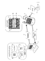
- FIG. 1 is a diagram illustrating a configuration of an attachment work support system constructed using the attachment work support apparatus according to the first embodiment.
- this attachment work support system is configured to include an attachment work support device 1, a 3D (three-dimensional) modeling system 2, and an RF reader 3 according to this embodiment.
- the attachment work support device 1 is specifically a portable personal computer (PC) equipped with a display device or a PDA. That is, it is realized by causing such a computer (data processing apparatus) to execute a program (attachment work support program) for supporting the attachment work for attaching the parts. Since the attachment work support device 1 is realized by such a computer, it is possible to cope with the attachment work by changing the place (object to which the part is attached).
- PC personal computer
- PDA personal digital assistant
- the attachment work support device 1 is realized as a support for wiring work for attaching a linear structure as a part.
- the 3D modeling system 2 is, for example, a database (DB) server that manages various design data such as objects and wiring paths.
- Data communication with the attachment work support device 1 is performed via a LAN having an access point, for example.
- DB database
- a linear structure only a cable having one connector at each end, that is, a linear structure in which two connectors that are detachable parts are connected by linear parts is assumed.
- Components for connecting the connectors are collectively referred to as “sockets”.
- the linear part connecting the two connectors is hereinafter referred to as a “signal line” in order to easily distinguish the cable 30 from the cable 30.
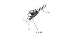
- FIG. 3 is a diagram for explaining a cable that is supported by the installation work support device 1 according to the present embodiment for support of wiring work. As shown in FIG. 3, the present embodiment is premised on supporting the wiring work of the cable 30 in which the IC tag (RFID tag) 32 is attached to each connector 31.
- the IC tag (RFID tag) 32 is attached to each connector 31.
- Each cable 30 is managed by cable information.
- This cable information has a configuration including, for example, data of a cable ID, a first IC tag ID, a second IC tag ID, a cable length, and a cable type.
- cable ID 101
- first IC tag ID 101A
- second IC tag ID 101B
- cable length 5 m
- cable type LAN cable
- the cable ID data can be obtained from any of the first and second IC tag ID data.
- the first IC tag ID data is stored as identification information in the IC tag 32 attached to one connector 31 of the cable 30, and the second IC tag ID data is stored in the IC tag 32 attached to the remaining connectors 31. Is stored as identification information.
- the RF reader 3 is for reading identification information (tag ID) from the IC tag 32 attached to the connector 31 of the cable 30.
- the RF reader 3 transmits the tag ID 4a to the attachment work support device 1 using, for example, a short-range wireless communication technology.
- the tag ID 4a may be transmitted / received using a communication technology other than the short-range wireless communication technology. That is, for example, transmission / reception may be performed by wire.
- a plurality of selectable communication technologies may be installed so that the user can select from the installed communication technologies. Here, for convenience, only short-range wireless communication technology is assumed.
- FIGS. 4A and 4B are diagrams illustrating an example of the RF reader 3.
- the connection of the connector 31 to the socket is usually performed by an operator holding the connector 31 in his hand. Therefore, in this embodiment, the communication unit 3a that reads the tag ID 4a from the IC tag 32 can be attached to the wrist or finger so that the tag ID 4a can be read only from the IC tag 32 of the connector 31 that is held by the worker. The thing is adopted.
- the attachment work support device 1 uses the data managed by the 3D modeling system 2 to display each socket to which each connector 31 of the cable 30 is connected and the wiring route, thereby supporting the wiring work for attaching the cable 30. To do. Since the apparatus is manufactured according to the design, the wiring path of the cable 30 designed in the virtual three-dimensional space using the design data represents the wiring path to which the cable 30 is actually attached. This is why the wiring work is supported using the data managed by the 3D modeling system 2. Since the design result of the wiring route can be used as it is for instructing the actual wiring work method, appropriate wiring work can be supported while suppressing the load.
- the 3D modeling system 2 from which the attachment work support device 1 acquires data manages, for example, a library DB 2a, a wiring information DB 2b, a configuration list DB 2c, and a cable information DB 2d as shown in FIG.
- the cable information DB 2d stores cable information for each cable 30.
- FIG. 5 is a diagram for explaining the server room where the cable 30 is wired.
- the server room 50 is designed to cope with an increase in the amount of data to be processed and the load, or to provide cloud computing. In a broad sense, it corresponds to an object (device) to which the cable 30 is to be attached.
- a plurality of racks 51 that can accommodate a plurality of servers 52 are arranged in the server room 50 that is the object. Accordingly, the cable 30 is used for connection between the servers 52 and the like.
- the data stored in each of the library DB 2a, the wiring information DB 2b, and the configuration list DB 2c will be described taking data related to the design of the server room 50 as an example.
- FIG. 6 is a conceptual diagram illustrating the configuration of the configuration list data.
- the configuration list data indicates a rack 51 arranged in the server room 50 and a server 52 mounted in each rack 51.
- Each rack 51 and server 52 is represented by model data representing a model, position data indicating a position (coordinates) arranged in a virtual three-dimensional space, angle data, and the like.
- the position data and the angle data are numerical data represented relatively on the basis of, for example, the upper component on the configuration list data. Accordingly, for example, in the rack 51, the position data represents the displacement of the reference point of the rack 51 from the reference point of the server room 50, and the angle data indicates the direction between the reference direction of the rack 52 and the reference direction of the server room 50. Represents the angle between.
- the component of the object is referred to as “part”, and the upper part is referred to as “parent part”.
- This angle data exists for each three-dimensional coordinate axis, but is ignored here for convenience.
- the position data and the angle data are not relative to the parent part as a reference, but can be selected based on the origin of the coordinate system of the virtual three-dimensional space (including the object). Yes. However, this is also ignored for convenience.
- the library DB 2a stores part data representing details of each part that can be arranged.
- FIG. 7 is a diagram for explaining the configuration of component data. As shown in FIG. 7, each component data has a configuration including product name data representing the name of the component, model data, socket data representing the provided socket, and 3D model data representing the shape and the like. FIG. 7 shows the rack data of the rack 51 and the server 52 as the component data.
- power source ⁇ 6 indicates that there are six power source sockets.
- 1000BASE-T”, “100BASE-T”, and “1000BASE-SX” all represent LAN standards.
- the notation following the LAN standard represents the number of sockets of the LAN standard and how to arrange them.
- “8 ⁇ 8” following “1000BASE-T” indicates that there are eight sockets of eight 1000BASE-T standard sockets.
- USB ⁇ 4 indicates that there are four USB standard sockets.
- RS-232C ⁇ 2 indicates that there are two RS-232C standard sockets.
- FIG. 8 is a diagram for explaining the arrangement of sockets represented by the 3D model data of the server 52.
- sockets are extracted and circled according to standards.
- the 3D model data is configured to include shape data representing the shape of the virtual three-dimensional space of the part (server 52) and position data representing the position of the socket represented by the shape data.
- This position data represents, for example, the displacement from the reference point of the server 52 and exists for each socket.
- an identification number is assigned to each socket separately for each type. Accordingly, the position data is managed together with, for example, an identification number and type data indicating the type of socket.
- the relative socket position relative to the parent part rack 51 is calculated using the socket position data and the server 52 position data.
- each server 52 has a large number of sockets.
- wiring information DB 2b wiring information that represents the result of the wiring design of the cable 30 is stored for each cable 30 that is connected to a socket mainly provided in any of the servers 52.
- FIG. 9 is a diagram for explaining the configuration of the wiring information.
- corresponding socket 1 data, corresponding socket 2 data, cable type data, passing position data, bundling position data, wiring rank data, and actual cable information are shown as data constituting the wiring information.
- the contents are shown with “:” in between.
- the content of the notation is an example of the cable 30 connecting the two servers 52 via a 1000BASE-SX socket.
- the data and contents are as follows.
- the wiring design of the cable 30 corresponds to, for example, determining a wiring route from the start point (socket) to the end point (another socket).
- Corresponding socket 1 data is data representing a socket designated as a starting point at the time of such wiring design.
- server 1 “LAN socket 1”, and “(9.95, 19.95, 1.1)” are servers to which 1 is assigned as an identification number (socket number). 1 is assigned as an identification number (socket number) among the LAN sockets installed in the server 52, and their positions (coordinates) are (9.95, 19.95, 1.1). ). “(9.95, 19.95, 1.1)” represented as the position (coordinate) data is based on the server room 50, for example.
- the server room 50 is used as a reference because the cable 30 may be connected between different racks 51. Thereby, it is not necessary to calculate the position of the socket in the server room 50, and the operator can easily understand the position more intuitively.
- each coordinate value of XYZ stores the position data of the server 52 and the server 62 in addition to the position data of the LAN socket. Calculation is performed using the position data of the rack 51.
- the corresponding socket 2 data is data representing a socket designated as an end point.
- the specific contents of “server 2”, “LAN socket 5”, and “(9.95, 19.6, 1.5)” are also installed in the server 52 to which 2 is assigned as the identification number. In the LAN socket installed in the server 52, 5 is assigned as an identification number, and its position (coordinates) is (9.95, 19.6, 1.5). .
- the cable type data is data representing the cable 30 to be used for connection between the sockets represented by the corresponding socket 1 data and the corresponding socket 2 data.
- the specific description “LAN cable ( ⁇ 5, 0.5 m)” indicates that the LAN cable having a thickness (width) of 5 mm and a length of 0.5 m is the cable 30 to be used. .
- the wiring path between the start point and the end point is performed by designating a position (passing position) through which the cable 30 should pass. Further, the position where the cable 30 should be fixed in the wiring path can be designated as a binding position. Thereby, the wiring route is designed as a line connecting the start point and the end point through the passing point and / or the binding position.
- the passing position data is data representing the designated passing position
- the binding position data is data representing the designated binding position.
- the passing position data and the binding position data exist for the number of positions designated by the designer. From this, FIG. 9 shows that the passage position is designated by two designers and the binding position is designated by one designer.
- Both the passing position data and the binding position data are data representing the position by, for example, displacement of the object (here, the server room 50) from the reference point. It is desirable to use the relative position data based on the reference point of the object when there are many cases where the servers 52 housed in different racks 51 are connected by the cable 30. However, when the servers 52 accommodated in the same rack 51 are connected by the cable 30, relative position data based on the reference point of the rack 51 may be employed.
- the XYZ coordinate values represented as the passing position data and the binding position data in FIG. 9 are the same in the XY coordinate values, but differ only in the Z coordinate values. This indicates that the designer changes only the position in the vertical direction of the server room 50 and designates two passing positions and one binding position.
- Bundled rank data is data representing the order in which wiring work should be performed.
- the order is assigned, for example, for each rack 51, and as the default value, for example, the order in which the wiring design is performed is automatically assigned.
- the actual cable information is information for specifying the cable 30 actually attached by wiring work, and includes cable ID data, first connector ID data, and second connector ID data.
- the first connector ID data the identification information read out first in the IC tag 32 attached to the connector 31 of the same cable 30 is stored.
- the read identification information is stored as second connector ID data.
- the cable ID data is stored together with the first connector ID data, for example.
- the attachment work support device 1 receives the part data managed by the 3D modeling system 2 and the wiring information 5 and the like, and includes an image including the part to which the cable 30 is attached and the wiring route of the cable 30 (hereinafter, for distinguishing from others). (Referred to as a “wiring image”).
- Reference numeral 6 in FIG. 1 represents the wiring image.
- 6 a represents a socket (starting point) to which the connector 31 of the cable 30 is to be attached
- 6 b represents a passing position through which the signal line should pass
- 6 c represents a binding position to which the signal line should be fixed.
- the wiring work of the cable 30 is supported by creating and displaying such a wiring image 6. For this reason, it is possible to support the attaching operation of the component regardless of the type of the component to be attached and the type of the object (device) to which the component is attached. Thereby, high versatility is realized.
- the IC tag 32 is attached to each connector 31 of the cable 30, and the operator who performs the wiring work attaches the RF reader 3 as shown in FIG. 4A or 4B to the hand.
- the operator who performs the wiring work attaches the RF reader 3 as shown in FIG. 4A or 4B to the hand.
- the RF reader 3 transmits the tag ID 4a read from the IC tag 32.
- the attachment work support device 1 identifies the process of the wiring work performed by the worker based on the tag ID 4a received from the RF reader 3, and wires information for supporting an appropriate wiring work according to the identification result.
- the instruction of the socket to which the first connector 31 is to be attached ⁇ the instruction of the wiring path of the signal line of the cable 30 according to the passing position or the binding position ⁇ the socket of the socket to which the second connector 31 is to be attached Information that indicates work contents to be performed in stages, such as instructions, is provided. In this way, in the example shown in FIG.
- the attachment work support device 1 receives the two tag IDs 4a from the RF reader 3.
- the two tag IDs 4a are stored as the first and second connector ID data of the actual cable information.
- the cable ID specified from the tag ID 4a is stored as cable ID data of actual cable information.
- the actual cable information 4 whose contents are determined in this way is transmitted from the attachment work support device 1 to the 3D modeling system 2 and registered in the wiring information DB 2b as shown in FIG.
- FIG. 2 is a diagram illustrating a functional configuration of the attachment work support device 1 according to the first embodiment.
- the configuration of the attachment work support device 1 that enables the instruction of work contents divided in stages as described above will be specifically described.
- the attachment work support device 1 has a configuration including a cable detection unit 11, an operation unit 12, a wiring information acquisition unit 13, a control unit 14, and an output unit 15. They have the following functions.
- the cable detection unit 11 detects the cable 30 (connector 31) held by the worker.
- the RF reader 3 reads out the IC tag 4a from the IC tag 32 attached to the connector 31 held by the operator. Accordingly, the cable detection unit 11 is realized as a unit that receives and processes the IC tag 4a transmitted from the RF reader 3 and identifies the process of wiring work.
- the operation unit 12 is for an operator to perform various operations. Specifically, it is realized by, for example, various keys and a circuit for detecting operations on the various keys.
- the wiring information acquisition unit 13 performs data communication with the 3D modeling system 2 and acquires information including the wiring information 5 from the 3D modeling system 2.
- the control unit 14 controls the entire installation work support device 1.
- a wiring information processing unit 14 a that generates a wiring image 6 using the wiring information 5 acquired by the wiring information acquisition unit 13 and the component data is provided.
- the output unit 15 displays the generated wiring image 6.
- FIG. 11 is a diagram illustrating an example of a hardware configuration of a computer to which the present embodiment can be applied.
- a configuration example of a computer that can be used as the attachment work support device 1 will be specifically described.
- the computer shown in FIG. 11 includes a CPU 61, a memory 62, an input device 63, an output device 64, an external storage device 65, a medium drive device 66, a network connection device 67, and a wireless communication device 68. It is a connected configuration.
- the configuration shown in the figure is an example, and the present invention is not limited to this.
- the CPU 61 controls the entire computer. Although only one is shown in FIG. 11, a plurality of CPUs 61 may be mounted.
- the memory 62 is a semiconductor memory such as a RAM that temporarily stores a program or data stored in the external storage device 65 (or the portable recording medium 70) during program execution, data update, or the like.
- the CPU 61 performs overall control by reading the program into the memory 62 and executing it.
- the input device 63 includes, for example, an operation device that is operated by an operator such as a keyboard and a detection device that detects an operation to the operation.
- the detection device detects a user operation on the operation device, and notifies the CPU 61 of the detection result.
- the output device 64 includes, for example, a display device and a display control device connected to the display device.
- the wiring image 6 shown in FIG. 1 is displayed on the display device of the output device 64.
- the external storage device 65 is a large-capacity storage device such as a flash memory or a hard disk device. Mainly used for storing various data and programs.
- the medium driving device 66 accesses a portable recording medium 70 such as a memory card.
- the network connection device 67 enables communication with an external device via a communication network, for example. Data communication with the 3D modeling system 2 is performed via the network connection device 67.
- the wireless communication device 68 enables short-range wireless communication. The reception of the IC tag transmitted from the RF reader 3 is performed by the wireless communication device 68, for example.
- the installation work support program is recorded in the external storage device 65 or the recording medium 70, or is acquired by the network connection device 67 via a communication network.
- the attachment work support apparatus 1 is realized by reading the attachment work support program into the memory 62 and executing it by the CPU 61.
- the units shown in FIG. 2 are realized by the following combinations.
- the installation work support program is stored in the external storage device 65
- data communication with the 3D modeling system 2 is performed via the network connection device 67
- data communication with the RF reader 3 is performed with the wireless communication device 68. Assume that this is done via
- the cable detection unit 11 is realized by the CPU 61, the memory 62, the external storage device 65, the wireless communication device 68, and the bus 69.
- the operation unit 12 is realized by the CPU 61, the memory 62, the input unit 63, the external storage device 65, and the bus 69.
- the wiring information acquisition unit 13 is realized by the CPU 61, the memory 62, the external storage device 65, the network connection device 67, and the bus 69.
- the control unit 14 is realized by the CPU 61, the memory 62, the external storage device 65, and the bus 69.
- the output unit 15 is realized by the CPU 61, the memory 62, the output device 64, the external storage device 65, and the bus 69.
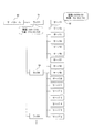
- FIG. 10A and 10B are flowcharts of the attachment work support process.
- operation of the attachment work assistance apparatus 1 is demonstrated in detail.
- This attachment work support process is realized by the CPU 61 of FIG. 11 executing the attachment work support program.
- 10A and 10B for the sake of convenience, in addition to the processing executed by the CPU 61, operations that the operator should perform for wiring work are also shown.
- the operation to be performed by the operator uses “OP”, and the process executed by the CPU 61 uses a code prefixed with “S”. Thereby, it will be described in detail together with operations to be performed by the operator.
- This installation work support process is started when the operator instructs the start of the wiring work (step OP1).
- the start instruction can actually be performed by selecting a place to be wired after starting the installation work support program.
- the configuration list data, the cable information DB 2d, the wiring information 5 for the location, and the component data of the components existing at the location are not particularly shown, but the 3D modeling system 2 sends the installation work support device according to the start instruction. 1 is transmitted.
- step S1 the CPU 61 that has received the start instruction searches for wiring information having the smallest value of the wiring rank data except for the wiring rank number, that is, the wire that has been wired, in the selected place. Extract wiring information.
- the actual cable information 4 is registered in the wiring information for which the corresponding wiring work has been completed.
- the wiring information 5 to be extracted by the 3D modeling system 2 is one in which the actual cable information 4 is not registered.
- the wiring image 6 is generated using the extracted wiring information 5, the 3D model data of the part, and the configuration list data. At this time, the configuration list data is used to determine the arrangement of the 3D model data of the part.
- the CPU 61 that has extracted the wiring information 5 displays the type, length, and the like of the cable 30 to be used for wiring work on the display device of the output device 64 in step S2. Thereafter, the process proceeds to step S3 and waits for recognition of the IC tag 32.
- the recognition of the IC tag 32 is performed by the RF reader 3, and the recognition of the IC tag 32 corresponds to receiving the tag ID 4 a from the RF reader 3.
- step OP2 The worker acquires the corresponding cable 30 according to the information displayed on the display device (step OP2), and holds one of the connectors 31 of the cable 30 (step OP3).
- the RF reader 3 reads the tag ID 4a from the IC tag 32 and transmits it.
- the CPU 61 shifts from step S3 to step S4.
- step S4 the CPU 61 acquires the tag ID 4a of the IC tag 32 of the connector 31 received from the RF reader 3.
- the CPU 61 stores the tag ID 4a acquired as the first connector ID data of the actual cable information 4 of the wiring information 5, and also stores the cable ID data obtained from the tag ID 4a.
- the CPU 61 causes the display device of the output device 64 to display the wiring image 6 that highlights (highlights) the socket 6a indicated by the corresponding socket 1 data of the wiring information.
- the highlighting of the socket 6a is performed in order to make it easy to understand the location of the socket into which the operator should insert the connector 31.
- highlighting is performed by a moving image that gradually reduces a relatively large circle surrounding the socket 6a or a moving image that changes the display state (display color or brightness) of the socket 6a. .
- This highlighting is realized by executing a subroutine process for displaying a moving image for highlighting.
- the socket 6a to be highlighted is specified by position data in the corresponding socket 1 data, for example. Therefore, in step S6, the execution prohibition of this subroutine process is canceled.
- the CPU 61 executes this subroutine process as step S7 separately from the attachment work support procedure until the execution is prohibited by releasing the execution prohibition. Since this subroutine processing can be realized by a well-known technique, the details are omitted here.
- the CPU 61 proceeds to step S8 and waits until the IC tag is not recognized.
- step OP4 the worker performs an operation of inserting the connector 31 into the socket into which the connector 31 is to be inserted
- step OP5 releases the hand from the connector 31
- step OP5 the transmission of the tag ID 4a from the RF reader 3
- step S9 the CPU 61 shifts from step S8 to step S9 in FIG. 10B.
- step S9 execution of the subroutine processing executed as step S7 is prohibited.
- step S9 the CPU 61 highlights the location on the wiring image 6 indicated by the passage position of the wiring information or the binding position data.
- This highlighting is realized, for example, by executing a subroutine process for sequentially changing the display state of the passing position or the binding position. Therefore, in step S9, the execution prohibition of this subroutine process is canceled.
- the CPU 61 executes this subroutine process as step S10 separately from the attachment work support process until the execution is prohibited by releasing the execution prohibition. Since this subroutine processing can also be realized by a known technique, details are omitted here.
- the CPU 61 proceeds to step S11 and waits to recognize the IC tag.
- step OP6 By highlighting the passing position or bundling position, the operator performs routing for passing the signal line through (step OP6), and then holds the connector 31 not inserted (step OP7). Thereby, the tag ID 4 a is transmitted from the RF reader 3. As a result, the CPU 61 shifts from step S11 to step S12. At the time of shifting to step S12, execution of the subroutine process of step S10 is prohibited.
- step S12 the CPU 61 acquires the tag ID 4a of the IC tag 32 of the connector 31 received from the RF reader 3.
- step S13 the CPU 61 stores the tag ID 4a acquired as the second connector ID data of the actual cable information 4 of the wiring information 5, and highlights the socket indicated by the corresponding socket 2 data of the wiring information 5.
- the wiring image 6 is displayed on the display device of the output device 64.
- the highlighting of the socket is realized, for example, by executing a subroutine process similarly to the highlighting of the socket 6a. Therefore, in step S13, the execution prohibition of this subroutine process is canceled.
- the CPU 61 executes this subroutine process as step S14 separately from the attachment work support process until the execution is prohibited by the execution prohibition cancellation. Since this subroutine process can be realized by a well-known technique like the other subroutine processes, details are omitted. After starting the highlighting of the socket, the CPU 61 proceeds to step S15 and waits until the IC tag is not recognized.
- step OP8 By highlighting the socket, the operator performs an operation of inserting the connector 31 into the socket into which the connector 31 is to be inserted (step OP8), and releases the hand from the connector 31 (step OP9). Thereby, the transmission of the tag ID 4a from the RF reader 3 is stopped. As a result, the CPU 61 shifts from step S15 to step S16. At the time of shifting to step S16, execution of the subroutine processing executed as step S14 is prohibited.
- step S16 the CPU 61 determines whether or not all the wiring work of the wiring information 5 received from the 3D modeling system 2 has been completed. If the received wiring information 5 does not contain the actual cable information 4, there is another wiring work to be performed, so the determination is NO and the process returns to step S1. Accordingly, the same processing is executed by changing the target wiring information 5. On the other hand, if there is no wiring information 5 in which the actual cable information 4 is not stored, it is determined that the wiring work at the location designated by the operator is finished, and the determination is YES. For example, the wiring information 5 including the actual cable information 4 Is transmitted to the 3D modeling system 2 to update the wiring information DB 2b, and then the attachment work support process is terminated.
- the progress of the wiring work is grasped by using the recognition result of the IC tag 32 by the RF reader 3, and the work support according to the progress situation is performed in a timely manner.
- the worker can easily confirm the work contents to be performed according to the situation at that time, and thus can perform the work quickly and appropriately.
- the image of the cable 30 for which the wiring work has been completed is deleted from the wiring image 6 so that only the cable 30 that is the object of the wiring work is arranged in the wiring image 6. This is to prevent the presence of another cable 30 from making it difficult to specify a socket or a wiring path to be inserted.
- the operator may have the connector 31 of the cable 30 to be used for wiring work for some reason.
- the RF reader 3 reads the tag ID 4a of the IC tag 32 of the connector 31 near the worker.
- the CPU 61 refers to the cable information stored in the received cable information DB 2d, and the operator selects the connector 31 of the appropriate cable 30 from the tag ID 4a received from the RF reader 3. It is also possible to check whether it is in your hand. Accordingly, when it is confirmed that the connector 31 of the appropriate cable 30 is not held in the hand, a message to that effect is displayed on the display device of the display device 64, and the connector 31 of the appropriate cable 30 is manually held. To encourage you to have
- the present embodiment assumes a wiring work for attaching the cable 30, but the assumed wiring work may be due to removal or replacement of the cable 30 or a change that changes a component (socket) to be connected.
- the wiring image 6 is generated by the attachment work support device 1, but may be generated by the 3D modeling system 2. Therefore, the attachment work support device 1 may be realized using a plurality of devices.
- the work content instruction in stages is performed by switching the data used for the instruction in the order of corresponding socket 1 data ⁇ passing position data and binding position data ⁇ corresponding socket 2 data. May be changed. That is, for example, the order of corresponding socket 1 data ⁇ corresponding socket 2 data ⁇ passing position data and binding position data, or passing position data and binding position data ⁇ corresponding socket 1 data ⁇ corresponding socket 2 data. The order may be arbitrarily selected by the operator.
- 3D model data of component data is used as image data for displaying a component including a socket into which the cable 30 is inserted.
- an operator can grasp the wiring work of the cable 30 without using 3D model data.
- FIG. 12 is a diagram for explaining a configuration of an installation work support system constructed using the installation work support apparatus according to the second embodiment.
- the attachment work support system includes an attachment work support device 1, a 3D (three-dimensional) modeling system 2, an RF reader 3, and a head mounted display (HMD) 1200. It has a configuration.
- the HMD 1200 is a well-known display of the type used by being worn on the head. Although a particularly detailed configuration is not shown, it includes a display device, a camera, an input device, and a communication device.
- the communication device is capable of short-range wireless communication, for example, similar to the RF reader 3.
- By operating the input device it is possible to perform photographing using a camera and transmission of an image obtained by photographing (hereinafter referred to as “camera image”).
- the attachment work support apparatus 1 acquires the camera image 1201 from the HMD 1200, generates a composite image 1220 in which the image of the cable 30 is arranged on the acquired camera image 1201, and transmits the composite image 1220 to the HMD 1200.
- FIG. 12 shows examples of the camera image 1201 and the composite image 1220 together.
- a captured image in a range including four markers 1201a is assumed. These four markers 1201a can be used for generation of an image of the cable 30 to be arranged in the camera image 1201 and determination of the arrangement position in addition to specifying the shooting location.
- the shooting location can be specified by, for example, printing a two-dimensional code on the marker 1201a.
- the generation of the image of the cable 30 and the determination of the arrangement are performed by, for example, specifying the position of the viewpoint in the virtual three-dimensional space from the positional relationship of the four markers 1201a.
- an image of the cable 30 is generated according to the positional relationship between the worker (HMD 1200) and the component (here, the rack 51 or the server 52) at the time of shooting and the shooting conditions, and the generated cable.
- a composite image 1220 is generated in such a manner that 30 images are arranged in the camera image 1201. Thereby, the operator can grasp the wiring route of the cable 30, that is, the socket into which the connector 31 is inserted and the signal line.
- the socket 6a into which the connector 31 of the cable 30 is to be inserted, the signal line passing position 6b, and the binding position 6c of the cable 30 are easily recognized visually by highlighting. Make it possible.
- the camera image 1201 shows the parts that the worker actually sees. For this reason, unlike the image expressed by the 3D model data, the possibility of giving the operator a sense of incongruity is extremely low. This makes it easier for the operator to grasp the socket into which the connector 31 is to be inserted, the passing position, and the like.
- the mounting work support device 1 in the second embodiment may be basically the same as the functional configuration of the mounting work support device 1 in the first embodiment shown in FIG.
- the wiring information acquisition unit 13 acquires a camera image 1201 from the HMD 1200
- the wiring information processing unit 14 a of the control unit 14 has a function of generating a composite image 1220 using the camera image 1201. May be.
- the output unit 15 may have a function of transmitting the composite image 1220 to the HMD 1200.
- the wiring information acquisition unit 13 is realized by the CPU 61, the memory 62, the external storage device 65, the network connection device 67, the wireless communication device 68, and the bus 69.
- the control unit 14 (wiring information processing unit 14a) is realized by the CPU 61, the memory 62, the external storage device 65, and the bus 69 as in the first embodiment.
- the output unit 15 is realized by the CPU 61, the memory 62, the external storage device 65, the wireless communication device 68, and the bus 69.
- the CPU 61 supports the wiring work by executing the attachment work support process shown in FIGS. 10A and 10B. Also in the second embodiment, the CPU 61 basically executes the same attachment work support process. However, in the second embodiment, an instruction to start the wiring work by the worker in step OP1 can be performed by transmitting the camera image 1201 from the HMD 1200. By recognizing the marker 1201 a in the camera image 1201, it is possible to specify a location to be a wiring work target. This camera image 1201 is used to generate a composite image 1220 to be displayed. Therefore, in the second embodiment, the composite image generation process shown in FIG. 13 is executed in step S1 of FIG. 10A. Here, the composite image generation processing will be described in detail with reference to FIG.
- step S21 the CPU 61 acquires the camera image 1201 received from the HMD 1200.
- step S22 the CPU 61 recognizes and extracts the position of the marker 1201a in the camera image 1201, and specifies the location represented by the marker 1201a. Thereafter, the process proceeds to step S ⁇ b> 23, and the CPU 61 acquires part data (3D model data), wiring information, and configuration list data of a part existing at the specified location from the 3D modeling system 2. After acquiring these data, the process proceeds to step S24.
- step S24 the CPU 61 collates the marker 1201a on the image in which the 3D model data of the part is arranged according to the configuration list data with the marker 1201a in the camera image 1201.
- step S25 the CPU 61 specifies the positional relationship between the parts present in the camera image 1201 and the worker, that is, the viewpoint in the virtual three-dimensional space, from the collation result. Thereafter, the process proceeds to step S26.
- step S26 a three-dimensional image of the cable 30 in which the wiring information having the smallest value of the connection order data excluding those that have been connected represents the wiring path is created.
- the CPU 61 creates a composite image 1220 by compositing the created three-dimensional image of the cable 30 with the camera image 1201.
- step S28 which is shifted after the creation, the CPU 61 transmits the composite image 1220 to the HMD 1200 for display. After the transmission, the composite image generation process is terminated.
- Subroutine processing executed as steps S7 and S14 in FIG. 10A and steps S10 and S14 in FIG. 10B change the display content of the composite image 1220 displayed by the HMD 1200, that is, the socket 6a, the passing position, the binding position, etc. Realize light display.
- step S1 is executed again due to the determination of NO in step S16, only steps S26 to S28 of the composite image generation process of FIG. 13 are executed. Thereby, a composite image 1220 for supporting the next wiring work is created.
- the wiring work is supported by displaying an image on the display device.
- the third embodiment uses a device different from the display device to support wiring work while maintaining high versatility.
- FIG. 14 is a diagram for explaining the configuration of an installation work support system constructed using the installation work support apparatus according to the third embodiment.
- the wiring route mounting work support system includes a mounting work support device 1, a 3D (three-dimensional) modeling system 2, an RF reader 3 (not shown), a laser pointer 1400, And a pan / tilt base 1410. Accordingly, the wiring path of the cable 30 is designated by the laser pointer 1400.
- the pan / tilt table 1410 is a moving device used to change the direction in which the laser pointer 1400 emits laser light.
- the mounting work support device 1 controls the pan / tilt table 1410 to use the laser beam emitted from the laser pointer 1400 to insert the connector 31, the signal line passing position, Alternatively, and / or is realized as an instruction for a binding position.
- the attachment work support device 1 in the third embodiment may be basically the same as the functional configuration of the attachment work support device 1 in the first embodiment shown in FIG. 2, as in the second embodiment. .
- the wiring information processing unit 14a in FIG. 2 has a function of calculating the control amount (rotation amount) in the vertical and horizontal directions of the pan / tilt table 1410 from the wiring information, for example.
- the output unit 15 has a function of operating the pan / tilt table 1410 according to the control amount.
- the configuration shown in FIG. 11 may include an interface with the pan / tilt table 1410 and the laser pointer 1400 instead of the wireless communication device 68.
- the output unit 15 is realized by the CPU 61, the memory 62, the external storage device 65, the two interfaces, and the bus 69.
- the position where the laser beam is irradiated varies depending on the positional relationship between the laser pointer 1400 and the parts. For this reason, in the third embodiment, adjustment is required so that the laser beam can be irradiated to an appropriate position.
- FIG. 15 is a flowchart for explaining the laser pointer setting procedure performed for this adjustment.
- This laser pointer setting is performed by an operator or the like in order to adjust the pan / tilt table 1410 to an appropriate state so that the wiring path can be appropriately indicated by the laser beam.
- This adjustment work is performed, for example, by causing the CPU 61 to execute a subprogram prepared in the attachment work support program.
- the operator determines a position where the laser pointer 1400 is installed (step S31), and installs the laser pointer 1400 on the pan / tilt table 1410 at the determined position (step S32).
- the operator operates an input device provided in or connected to the attachment work support device 1 to irradiate the laser pointer 1400 with laser light, and a characteristic position on the component, for example, one
- the pan / tilt base 1410 is driven so that the socket is irradiated with laser light (step S33).
- the operator operates the input device to adjust the pan / tilt table 1410 so that the laser beam irradiates a characteristic position (step S34).
- the sub-program of the installation work support program repeats the adjustment as described above, so that the position in the virtual three-dimensional space, the change in position, and the rotation amount for driving the pan / tilt table 1410 according to the change are determined. Learn the correspondence between and save the learning results.
- the instruction of the wiring route when supporting the wiring work is performed by calculating the rotation amount of the pan / tilt table 1410 from the position in the virtual three-dimensional space indicated by the wiring information using the learning result.
- Such an instruction of the wiring route itself can be basically performed by executing an attachment work support process as shown in FIGS. 10A and 10B as in the first and second embodiments.
- the route through which the signal line of the cable 30 passes is specified in such a way that the passing position and the binding position are emphasized (highlighted). Another method may be adopted as long as the route through the line can be easily presented to the operator. That is, the route instruction method is not particularly limited.
- the route instruction is performed using the display device or the laser pointer 1400, but the route instruction may be performed using another device. As is clear from the above, various modifications may be made.
Landscapes
- Engineering & Computer Science (AREA)
- Business, Economics & Management (AREA)
- Physics & Mathematics (AREA)
- General Physics & Mathematics (AREA)
- Theoretical Computer Science (AREA)
- Human Resources & Organizations (AREA)
- Strategic Management (AREA)
- Entrepreneurship & Innovation (AREA)
- Economics (AREA)
- Computer Hardware Design (AREA)
- Tourism & Hospitality (AREA)
- Marketing (AREA)
- General Business, Economics & Management (AREA)
- Health & Medical Sciences (AREA)
- Toxicology (AREA)
- Quality & Reliability (AREA)
- Operations Research (AREA)
- General Health & Medical Sciences (AREA)
- Electromagnetism (AREA)
- Computer Networks & Wireless Communication (AREA)
- Artificial Intelligence (AREA)
- Computer Vision & Pattern Recognition (AREA)
- Microelectronics & Electronic Packaging (AREA)
- Development Economics (AREA)
- Educational Administration (AREA)
- Game Theory and Decision Science (AREA)
- Electric Cable Installation (AREA)
- General Factory Administration (AREA)
Abstract
Dans un système dans lequel la présente invention est appliquée, des informations d'identification servant à identifier une pièce et des informations d'installation servant à spécifier l'endroit auquel la pièce doit être installée sur un premier appareil sont stockées sous la forme d'un ensemble, et des informations d'identification concernant la pièce qui ont été lues et envoyées par un second appareil sont reçues. Ensuite, une recherche est réalisée dans une unité de stockage pour y trouver les informations d'identification reçues, et des informations d'installation correspondant aux informations d'identification qui ont été trouvées en résultat de la recherche sont combinées à une image du premier appareil, créant une première image composite.
Priority Applications (4)
| Application Number | Priority Date | Filing Date | Title |
|---|---|---|---|
| PCT/JP2010/001804 WO2011111122A1 (fr) | 2010-03-12 | 2010-03-12 | Dispositif d'aide au travail d'installation, procédé correspondant et programme |
| EP10847355.4A EP2546940A4 (fr) | 2010-03-12 | 2010-03-12 | Dispositif d'aide au travail d'installation, procédé correspondant et programme |
| JP2012504162A JPWO2011111122A1 (ja) | 2010-03-12 | 2010-03-12 | 取付作業支援装置、方法、及びプログラム |
| US13/605,367 US20130083057A1 (en) | 2010-03-12 | 2012-09-06 | Installing operation support device and method |
Applications Claiming Priority (1)
| Application Number | Priority Date | Filing Date | Title |
|---|---|---|---|
| PCT/JP2010/001804 WO2011111122A1 (fr) | 2010-03-12 | 2010-03-12 | Dispositif d'aide au travail d'installation, procédé correspondant et programme |
Related Child Applications (1)
| Application Number | Title | Priority Date | Filing Date |
|---|---|---|---|
| US13/605,367 Continuation US20130083057A1 (en) | 2010-03-12 | 2012-09-06 | Installing operation support device and method |
Publications (1)
| Publication Number | Publication Date |
|---|---|
| WO2011111122A1 true WO2011111122A1 (fr) | 2011-09-15 |
Family
ID=44562971
Family Applications (1)
| Application Number | Title | Priority Date | Filing Date |
|---|---|---|---|
| PCT/JP2010/001804 Ceased WO2011111122A1 (fr) | 2010-03-12 | 2010-03-12 | Dispositif d'aide au travail d'installation, procédé correspondant et programme |
Country Status (4)
| Country | Link |
|---|---|
| US (1) | US20130083057A1 (fr) |
| EP (1) | EP2546940A4 (fr) |
| JP (1) | JPWO2011111122A1 (fr) |
| WO (1) | WO2011111122A1 (fr) |
Cited By (5)
| Publication number | Priority date | Publication date | Assignee | Title |
|---|---|---|---|---|
| JP2015188284A (ja) * | 2014-03-27 | 2015-10-29 | 日本電気株式会社 | 端末、サーバ、作業支援システム、作業支援方法 |
| JP2017120516A (ja) * | 2015-12-28 | 2017-07-06 | 株式会社リコー | 情報処理装置、プログラム、部品確認方法、情報処理システム |
| JP2019531545A (ja) * | 2016-09-01 | 2019-10-31 | ジョーボティクス インコーポレイテッド | ブレッドボード及び電子機器実験システム |
| JPWO2020250928A1 (fr) * | 2019-06-11 | 2020-12-17 | ||
| JP2022163059A (ja) * | 2019-03-11 | 2022-10-25 | 株式会社日立製作所 | 作業指示システムおよび方法 |
Families Citing this family (3)
| Publication number | Priority date | Publication date | Assignee | Title |
|---|---|---|---|---|
| JP6252735B2 (ja) * | 2013-08-26 | 2017-12-27 | ブラザー工業株式会社 | 画像処理プログラム |
| US20150178524A1 (en) * | 2013-12-23 | 2015-06-25 | Hyundai Motor Company | System and method for wiring circuit verification of vehicle |
| JP2021022057A (ja) * | 2019-07-25 | 2021-02-18 | ファナック株式会社 | 設置支援装置、設置支援システム及び設置支援プログラム |
Citations (5)
| Publication number | Priority date | Publication date | Assignee | Title |
|---|---|---|---|---|
| JP2003308585A (ja) * | 2001-08-24 | 2003-10-31 | Akiji Matoba | 災害警報装置 |
| JP2004013722A (ja) * | 2002-06-10 | 2004-01-15 | Nec Fielding Ltd | 敷設工事評価方法およびシステム |
| JP2005196263A (ja) * | 2003-12-26 | 2005-07-21 | Brother Ind Ltd | 無線タグ読み取り装置 |
| JP2006271154A (ja) * | 2005-03-25 | 2006-10-05 | Jfe Engineering Kk | 機器・ケーブル接続管理方法およびシステム |
| JP2007151383A (ja) | 2005-10-28 | 2007-06-14 | Hitachi Ltd | Rfidシステム,rfidケーブルシステム,rfidケーブル敷設方法 |
Family Cites Families (9)
| Publication number | Priority date | Publication date | Assignee | Title |
|---|---|---|---|---|
| US5742263A (en) * | 1995-12-18 | 1998-04-21 | Telxon Corporation | Head tracking system for a head mounted display system |
| JP2000164050A (ja) * | 1998-11-27 | 2000-06-16 | Sumitomo Wiring Syst Ltd | ワイヤーハーネスの組立作業支援システム |
| DE10103922A1 (de) * | 2001-01-30 | 2002-08-01 | Physoptics Opto Electronic Gmb | Interaktives Datensicht- und Bediensystem |
| JP4522140B2 (ja) * | 2004-05-14 | 2010-08-11 | キヤノン株式会社 | 指標配置情報推定方法および情報処理装置 |
| JP2006039448A (ja) * | 2004-07-30 | 2006-02-09 | Seiko Epson Corp | 電子機器、ケーブル、及び電子機器システム |
| US20090322671A1 (en) * | 2008-06-04 | 2009-12-31 | Cybernet Systems Corporation | Touch screen augmented reality system and method |
| US8400548B2 (en) * | 2010-01-05 | 2013-03-19 | Apple Inc. | Synchronized, interactive augmented reality displays for multifunction devices |
| US20110248995A1 (en) * | 2010-04-09 | 2011-10-13 | Fuji Xerox Co., Ltd. | System and methods for creating interactive virtual content based on machine analysis of freeform physical markup |
| EP2405402A1 (fr) * | 2010-07-06 | 2012-01-11 | EADS Construcciones Aeronauticas, S.A. | Procédé et système pour assembler des composants |
-
2010
- 2010-03-12 JP JP2012504162A patent/JPWO2011111122A1/ja active Pending
- 2010-03-12 EP EP10847355.4A patent/EP2546940A4/fr not_active Withdrawn
- 2010-03-12 WO PCT/JP2010/001804 patent/WO2011111122A1/fr not_active Ceased
-
2012
- 2012-09-06 US US13/605,367 patent/US20130083057A1/en not_active Abandoned
Patent Citations (5)
| Publication number | Priority date | Publication date | Assignee | Title |
|---|---|---|---|---|
| JP2003308585A (ja) * | 2001-08-24 | 2003-10-31 | Akiji Matoba | 災害警報装置 |
| JP2004013722A (ja) * | 2002-06-10 | 2004-01-15 | Nec Fielding Ltd | 敷設工事評価方法およびシステム |
| JP2005196263A (ja) * | 2003-12-26 | 2005-07-21 | Brother Ind Ltd | 無線タグ読み取り装置 |
| JP2006271154A (ja) * | 2005-03-25 | 2006-10-05 | Jfe Engineering Kk | 機器・ケーブル接続管理方法およびシステム |
| JP2007151383A (ja) | 2005-10-28 | 2007-06-14 | Hitachi Ltd | Rfidシステム,rfidケーブルシステム,rfidケーブル敷設方法 |
Non-Patent Citations (1)
| Title |
|---|
| See also references of EP2546940A4 |
Cited By (9)
| Publication number | Priority date | Publication date | Assignee | Title |
|---|---|---|---|---|
| JP2015188284A (ja) * | 2014-03-27 | 2015-10-29 | 日本電気株式会社 | 端末、サーバ、作業支援システム、作業支援方法 |
| JP2017120516A (ja) * | 2015-12-28 | 2017-07-06 | 株式会社リコー | 情報処理装置、プログラム、部品確認方法、情報処理システム |
| JP2019531545A (ja) * | 2016-09-01 | 2019-10-31 | ジョーボティクス インコーポレイテッド | ブレッドボード及び電子機器実験システム |
| JP7126494B2 (ja) | 2016-09-01 | 2022-08-26 | ジョーボティクス インコーポレイテッド | ブレッドボード及び電子機器実験システム |
| JP2022163059A (ja) * | 2019-03-11 | 2022-10-25 | 株式会社日立製作所 | 作業指示システムおよび方法 |
| JP7377318B2 (ja) | 2019-03-11 | 2023-11-09 | 株式会社日立製作所 | 作業指示システム |
| JPWO2020250928A1 (fr) * | 2019-06-11 | 2020-12-17 | ||
| WO2020250928A1 (fr) * | 2019-06-11 | 2020-12-17 | 日本電気株式会社 | Système d'aide au travail de connexion de câble, procédé d'aide au travail de connexion de câble et programme d'assistance au travail de connexion de câble |
| JP7283541B2 (ja) | 2019-06-11 | 2023-05-30 | 日本電気株式会社 | ケーブル接続作業支援システム、ケーブル接続作業支援方法、およびケーブル接続作業支援プログラム |
Also Published As
| Publication number | Publication date |
|---|---|
| JPWO2011111122A1 (ja) | 2013-06-27 |
| EP2546940A4 (fr) | 2013-08-07 |
| EP2546940A1 (fr) | 2013-01-16 |
| US20130083057A1 (en) | 2013-04-04 |
Similar Documents
| Publication | Publication Date | Title |
|---|---|---|
| WO2011111122A1 (fr) | Dispositif d'aide au travail d'installation, procédé correspondant et programme | |
| US10789775B2 (en) | Method for controlling an object | |
| Blaga et al. | Augmented reality integration into MES for connected workers | |
| ES2963321T3 (es) | Sistema de producción de mazos de cables | |
| KR102657309B1 (ko) | 전기 스위칭 시스템을 탑재하기 위한 방법 및 그러한 스위칭 시스템의 조립을 단순화하기 위한 조립 지원 디바이스 | |
| JP5247854B2 (ja) | 集荷システムおよび集荷方法 | |
| KR20120069654A (ko) | 정보 처리 장치, 정보 처리 방법 및 프로그램 | |
| JP2011248860A (ja) | 情報処理システム、情報処理方法及びプログラム | |
| CN109074414A (zh) | 用于配置配电箱的方法及系统 | |
| JP2020518217A (ja) | 特にスイッチキャビネット内または組立システム上に配置された部品の、接続作業の自動的なサポート方法およびサポート用システム | |
| JP6803794B2 (ja) | 画像処理装置及び製造システム | |
| CN114567535B (zh) | 一种基于增强现实的产品交互与故障诊断方法 | |
| US8150661B2 (en) | Design support system, method and storage medium for a route design for a deformable linear structure | |
| JP6639786B2 (ja) | ワイヤハーネスの製造支援システム | |
| KR20210086207A (ko) | 증강현실 기반 작업 공정 모니터링 및 작업 숙련도 평가방법 | |
| JP2007018188A (ja) | 拡張現実感による情報提示システム、情報提示方法、情報提示装置およびコンピュータプログラム | |
| US20100305908A1 (en) | Harness verification apparatus, harness verification method and storage medium | |
| KR102398584B1 (ko) | 헤드 마운트 디스플레이 및 제어 방법 | |
| JP6571723B2 (ja) | 動作プログラムを生成するプログラミング装置、及びプログラム生成方法 | |
| JP2020135588A (ja) | 制御システム | |
| US11030359B2 (en) | Method and system for providing mixed reality service | |
| JP7065795B2 (ja) | データ作成システム及びデータ作成方法 | |
| JP6445935B2 (ja) | 作業支援装置、作業支援方法及び作業支援プログラム | |
| CN113759910A (zh) | 一种建图的方法、装置、电子设备及存储介质 | |
| JP7143641B2 (ja) | 情報処理装置、情報処理方法、およびプログラム |
Legal Events
| Date | Code | Title | Description |
|---|---|---|---|
| 121 | Ep: the epo has been informed by wipo that ep was designated in this application |
Ref document number: 10847355 Country of ref document: EP Kind code of ref document: A1 |
|
| WWE | Wipo information: entry into national phase |
Ref document number: 2012504162 Country of ref document: JP |
|
| WWE | Wipo information: entry into national phase |
Ref document number: 2010847355 Country of ref document: EP |
|
| NENP | Non-entry into the national phase |
Ref country code: DE |