WO2011111309A1 - Procédé de mesure thermique à l'aide d'un capteur pyroélectrique de température - Google Patents
Procédé de mesure thermique à l'aide d'un capteur pyroélectrique de température Download PDFInfo
- Publication number
- WO2011111309A1 WO2011111309A1 PCT/JP2011/000888 JP2011000888W WO2011111309A1 WO 2011111309 A1 WO2011111309 A1 WO 2011111309A1 JP 2011000888 W JP2011000888 W JP 2011000888W WO 2011111309 A1 WO2011111309 A1 WO 2011111309A1
- Authority
- WO
- WIPO (PCT)
- Prior art keywords
- upper electrode
- temperature
- channel
- ferroelectric
- semiconductor layer
- Prior art date
- Legal status (The legal status is an assumption and is not a legal conclusion. Google has not performed a legal analysis and makes no representation as to the accuracy of the status listed.)
- Ceased
Links
Images





Classifications
-
- H—ELECTRICITY
- H10—SEMICONDUCTOR DEVICES; ELECTRIC SOLID-STATE DEVICES NOT OTHERWISE PROVIDED FOR
- H10N—ELECTRIC SOLID-STATE DEVICES NOT OTHERWISE PROVIDED FOR
- H10N15/00—Thermoelectric devices without a junction of dissimilar materials; Thermomagnetic devices, e.g. using the Nernst-Ettingshausen effect
- H10N15/10—Thermoelectric devices using thermal change of the dielectric constant, e.g. working above and below the Curie point
-
- G—PHYSICS
- G01—MEASURING; TESTING
- G01K—MEASURING TEMPERATURE; MEASURING QUANTITY OF HEAT; THERMALLY-SENSITIVE ELEMENTS NOT OTHERWISE PROVIDED FOR
- G01K7/00—Measuring temperature based on the use of electric or magnetic elements directly sensitive to heat ; Power supply therefor, e.g. using thermoelectric elements
- G01K7/36—Measuring temperature based on the use of electric or magnetic elements directly sensitive to heat ; Power supply therefor, e.g. using thermoelectric elements using magnetic elements, e.g. magnets, coils
Definitions
- the present invention relates to a method for measuring temperature using a pyroelectric temperature sensor.
- Patent Document 1 discloses a conventional pyroelectric temperature sensor having a pyroelectric body / semiconductor structure.
- FIG. 14 is a cross-sectional view of the pyroelectric temperature sensor disclosed in Patent Document 1.
- the pyroelectric temperature sensor includes a pyroelectric thin film 101, a sensor electrode 102, a semiconductor thin film 103, a source electrode 104, a drain electrode 105, an interlayer insulating film 106, and a lead electrode 107.
- the potential in the vicinity of the interface between the pyroelectric thin film 101 and the semiconductor layer 103 is modulated by the pyroelectric effect caused by the temperature change. This modulation forms a channel region or depletion layer. This formation greatly changes the conductivity. In this way, a change in temperature in the pyroelectric thin film is converted into a change in the drain current of the thin film transistor.
- Patent Document 1 an effect exceeding the amplification characteristics of the thin film transistor cannot be obtained. Furthermore, the detection of the drain current amount requires a complicated external circuit.
- An object of the present invention is to provide a method for measuring temperature using a small pyroelectric temperature sensor having higher sensitivity.
- the present invention provides a method for measuring temperature using a temperature sensor.
- the method comprises the following steps: Preparing the temperature sensor;
- the temperature sensor includes a lower electrode group, a ferroelectric layer, a semiconductor layer, and an upper electrode group,
- the lower electrode group, the ferroelectric layer, the semiconductor layer, and the upper electrode group are laminated in this order
- the lower electrode group includes a first lower electrode and a second lower electrode
- the upper electrode group includes a first upper electrode, a second upper electrode, and a third upper electrode,
- the second upper electrode is sandwiched between the first upper electrode and the third upper electrode;
- a first ferroelectric portion of the ferroelectric layer is sandwiched between the first lower electrode and the first upper electrode;
- a second ferroelectric portion of the ferroelectric layer is sandwiched between the second lower electrode and the third upper electrode;
- the polarization direction of the first ferroelectric portion is opposite to the polarization direction of the second ferroelectric portion;
- a first channel is formed in a portion
- the above temperature sensor is also included in the spirit of the present invention.
- a temperature measuring device provided with the above temperature sensor and arithmetic device is also included in the spirit of the present invention.
- the arithmetic device includes a processing unit, a storage unit, an output unit, and an input unit, An output voltage V OUT from the second upper electrode is input to the input unit,
- the storage unit stores a constant Rd1, a constant Ru1, a constant Rd2, and a constant Ru2.
- the processing unit calculates the temperature T based on the above equation (2) while referring to the storage unit,
- the output unit outputs the calculated temperature T.
- the present invention provides a method for measuring temperature using a highly sensitive pyroelectric temperature sensor.
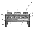
- FIG. 1 shows a pyroelectric temperature sensor according to the first embodiment.
- FIG. 2 is a top view of the pyroelectric temperature sensor according to the first embodiment.
- FIG. 3 shows a sectional view of the pyroelectric temperature sensor in the initial state.
- FIG. 4 shows a method for determining the direction of the polarization 17.
- FIGS. 5A and 5B show a method of measuring the resistance values of the first channel 21 and the second channel 23, respectively.
- FIG. 6 shows a method for manufacturing a pyroelectric temperature sensor.
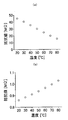
- FIG. 7A shows the relationship between the temperature and the resistance value of the first channel 21 in the first embodiment.
- FIG. 7B shows the relationship between the temperature and the resistance value of the second channel 23.
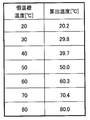
- FIG. 8 shows a table comparing the temperature of the thermostatic chamber and the temperature calculated from the output voltage in Example 1.
- FIG. 9 shows a graph in which the horizontal axis represents the channel size ratio ⁇ and the vertical axis represents the output change in the second embodiment.
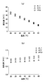
- FIG. 10A shows the relationship between the temperature in Example 3 and the resistance value of the first channel 21 when different materials are used in the ferroelectric layer 7.
- FIG. 10B shows the relationship between the temperature in Example 3 and the resistance value of the second channel 23 when different materials are used in the ferroelectric layer 7.
- FIG. 11 shows a table comparing the temperature of the thermostatic chamber and the calculated temperature from the output voltage in Example 3.
- FIG. 12 shows the relationship between the thickness of the ferroelectric layer 7 and the output voltage of the pyroelectric temperature sensor when the temperature rises from 20 ° C. to 80 ° C. in Example 4.
- FIG. 13 shows the relationship between the thickness of the semiconductor layer 9 and the output voltage of the pyroelectric temperature sensor when the temperature rises from 20 ° C. to 80 ° C. in Example 5.
- FIG. 14 is a cross-sectional view of the pyroelectric temperature sensor disclosed in Patent Document 1.
- FIG. 15 shows the pyroelectric temperature sensor 1 and the arithmetic unit of the present invention.
- FIG. 1 shows a pyroelectric temperature sensor according to the first embodiment.
- the pyroelectric temperature sensor 1 includes a substrate 2, a support film 3, lower electrode groups 5 and 6, a ferroelectric layer 7, a semiconductor layer 9, and upper electrode groups 11, 13, and 15. It has.
- the lower electrode groups 5 and 6, the ferroelectric layer 7, the semiconductor layer 9, and the upper electrode groups 11, 13, and 15 are laminated in this order.
- the lower electrode group includes a first lower electrode 5 and a second lower electrode 6.
- the upper electrode group includes a first upper electrode 11, a second upper electrode 13, and a third upper electrode 15.
- the second upper electrode 13 is sandwiched between the first upper electrode 11 and the third upper electrode 15.
- the first ferroelectric portion 7 a of the ferroelectric layer 7 is sandwiched between the first lower electrode 5 and the first upper electrode 11.
- the second ferroelectric portion 7 b of the ferroelectric layer 7 is sandwiched between the second lower electrode 6 and the third upper electrode 15.
- the second ferroelectric portion 7b has a polarization direction opposite to the polarization direction of the first ferroelectric portion 7a.
- the first channel 21 is formed in the portion of the semiconductor layer 9 sandwiched between the first upper electrode 11 and the second upper electrode 13.
- the first ferroelectric portion 7 a is located below the first channel 21.
- the second channel 23 is formed in the portion of the semiconductor layer 9 sandwiched between the second upper electrode 13 and the third upper electrode 15.
- the second ferroelectric portion 7 b is located below the second channel 23.
- 1, 3, 4, and 5 indicate the direction of polarization 17.
- a positive charge is biased at the tip of the arrow.
- the polarization 17 is defined to be upward when the tip of the arrow faces the semiconductor layer 9.
- the polarization 17 is defined as downward.
- the output voltage V out represents the potential of the second upper electrode 13 measured by the voltmeter 81.
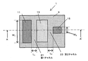
- FIG. 2 is a top view of the pyroelectric temperature sensor according to the first embodiment.
- FIG. 1 is a cross-sectional view taken along line A-A ′ of FIG.
- the first upper electrode 11 and the second upper electrode 13 function as a drain electrode and a source electrode of the first channel 21, respectively.
- the second upper electrode 13 and the third upper electrode 15 function as a drain electrode and a source electrode of the second channel 23, respectively.
- the first channel 21 has a width of W 1 and a length of L 1 .
- the second channel 23 has a width of W 2 and a length of L 2 .
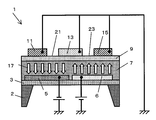
- FIG. 3 shows a cross-sectional view of the pyroelectric temperature sensor in the initial state. As shown in FIG. 3, in the initial state, the direction of polarization 17 is often not determined.
- FIG. 4 shows a method for determining the direction of the polarization 17.
- a negative voltage and a positive voltage are applied to the first lower electrode 5 and the second lower electrode 6 while the first upper electrode 11, the second upper electrode 13, and the third upper electrode 15 are grounded. Is applied. Thereafter, the voltage is removed.
- the polarization 17 is determined as shown in FIG. That is, the direction of the polarization 17 in the first ferroelectric portion 7a of the ferroelectric layer 7 located below the first channel 21 is determined so as to be downward.
- the direction of the polarization 17 in the second ferroelectric portion 7b of the ferroelectric layer 7 located below the second channel 23 is determined to be upward.
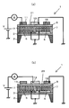
- FIGS. 5A and 5B show a method of measuring the resistance values of the first channel 21 and the second channel 23, respectively.
- a positive voltage is applied to the first upper electrode 11 while the second upper electrode 13, the first lower electrode 5, and the second lower electrode 6 are grounded, and the first channel The value of the current flowing through 21 is measured. Furthermore, the relationship between the resistance value of the first channel 21 and the temperature is obtained by changing the temperature of the pyroelectric temperature sensor 1 using a heating means (not shown).
- a positive voltage is applied to the second upper electrode 13 while the third upper electrode 15, the first lower electrode 5, and the second lower electrode 6 are grounded, and the second channel The value of the current flowing through 23 is measured.
- the relationship between the resistance value of the second channel 23 and the temperature is obtained by changing the temperature of the pyroelectric temperature sensor 1 using a heating means (not shown).
- resistance values R d1 , R u1 , R d2 and R u2 are obtained.
- R d1 represents the resistance value of the first channel 21 when the temperature T of the ferroelectric layer 7 is T 1 .
- R u1 represents the resistance value of the second channel 23 when the temperature T of the ferroelectric layer 7 is T 1 .
- R d2 represents the resistance value of the first channel 21 when the temperature T of the ferroelectric layer 7 is T 2 .
- R u2 represents the resistance value of the second channel 23 when the temperature T of the ferroelectric layer 7 is T 2 .
- the power supply voltage V DD is applied to the first upper electrode 11.
- the power supply voltage V DD is distributed according to the resistance value R u of the resistance R d and the second channel 23 of the first channel 21, and the potential of the second upper electrode 13 is output as the output voltage V out.
- the present inventors obtain the temperature T of the ferroelectric layer 7. It was found that ° C can be measured.
- the present inventors have found that the resistance value of a channel is proportional to the temperature of the channel. Furthermore, the present inventors have also found a relationship that when the polarization direction in the ferroelectric layer 7 is reversed, the proportional gradient is also reversed.
- the resistance value of the first channel 21 decreases.
- the decrease in the resistance value of the first channel 21 is proportional to the increase in the temperature.
- the resistance value of the second channel 23 increases.
- the increase in the resistance value of the second channel 23 is proportional to the increase in the temperature.
- the resistance value of the first channel 21 increases.
- the increase in the resistance value of the first channel 21 is proportional to the decrease in the temperature.
- the resistance value of the second channel 23 decreases.
- the decrease in the resistance value of the second channel 23 is proportional to the decrease in the temperature.
- the pyroelectric temperature sensor of the present invention can be used for temperature measurement at 150 ° C. or lower. When the temperature exceeds 150 ° C., polarization can become unstable.
- the pyroelectric temperature sensor of the present invention is preferably used for temperature measurement of ⁇ 20 ° C. or higher.
- the pyroelectric temperature sensor of the present invention has higher sensitivity to temperature than the conventional pyroelectric temperature sensor.
- the temperature measuring device of the present invention includes the pyroelectric temperature sensor and the arithmetic device described above.
- the arithmetic device includes a processing unit, a storage unit, an output unit, and an input unit.
- the output voltage V OUT from the second upper electrode 13 is input to the input unit.
- the storage unit stores a constant Rd 1 , a constant Ru 1 , a constant Rd 2 , and a constant Ru 2 . These constants are stored in the storage unit until the temperature measuring device mass-produced in the factory is shipped from the factory. That is, a temperature measuring device in which these constants are stored at the time of factory shipment is included in the spirit of the present invention.
- the user of the temperature measuring device of the present invention causes the temperature sensor to touch an object for which the user wants to know the temperature.
- the processing unit calculates the temperature T based on the above equation (2) while referring to the storage unit. Then, the output unit outputs the calculated temperature T. In this way, the user knows the temperature T of the object.
- the object can be a gas, a liquid, or a solid.
- FIG. 6 shows a method for manufacturing a pyroelectric temperature sensor.
- A An SrTiO 3 thin film having a thickness of 150 nm is deposited on the MgO (100) single crystal substrate 2 at a temperature of 700 ° C. by a pulsed laser deposition method (hereinafter referred to as “PLD method”). Film 3 was formed.
- PLD method pulsed laser deposition method
- a platinum film having a thickness of 200 nm was deposited by the PLD method.
- a resist (not shown) was applied and patterned to form an etching mask.
- the platinum film was etched by a reactive ion etching method using CF 4 gas. Thereafter, the resist was removed, and the first lower electrode 5 and the second lower electrode 6 were formed as shown in FIG.
- a resist (not shown) was applied and patterned. Further, a platinum film having a thickness of 50 nm was deposited using EB vapor deposition. As shown in FIG. 6C, the first upper electrode 11, the second upper electrode 13, and the third upper electrode 15 were formed by using a lift-off method for removing the resist.
- Example 1 the width W 1 and length L 1 of the first channel 21 and the width W 2 and length L 2 of the second channel 23 were 1000 ⁇ m, 1 ⁇ m, 10 ⁇ m, and 10 ⁇ m, respectively.
- the channel size ratio ⁇ was 1000.
- the pyroelectric temperature sensor was placed in a constant temperature bath (not shown) at 20 ° C., and the resistance value R d1 of the first channel 21 and the resistance value R u1 of the second channel 23 were measured.
- R d1 was 45 megohm and R u1 was 0.86 megohm.
- the temperature of the constant temperature bath was changed to 30 ° C., 40 ° C., 50 ° C., 60 ° C., and 70 ° C., and the resistance value of the first channel 21 and the resistance value of the second channel 23 were measured.
- the temperature of the thermostatic chamber was changed to 80 ° C., and the resistance value R d2 of the first channel 21 and the resistance value R u2 of the second channel 23 were measured.
- R d2 was 16 megohms and R u2 was 1.0 megohms.
- FIG. 7A shows the relationship between the temperature and the resistance value of the first channel 21 obtained by the above measurement.
- FIG. 7B shows the relationship between the temperature and the resistance value of the second channel 23.
- the power supply voltage V DD was 100 mV.
- FIG. 8 shows a table comparing the temperature of the thermostat and the temperature calculated from the output voltage based on equation (2). As shown in FIG. 8, the actual temperature coincided with the calculated temperature.
- FIG. 9 is a graph in which the horizontal axis represents the channel size ratio ⁇ and the vertical axis represents the change in output voltage.
- the change in output voltage means a change in the output voltage of the pyroelectric temperature sensor when the temperature rises from 20 ° C. to 80 ° C. As shown in FIG. 9, the output change increases as ⁇ increases. Since the detection lower limit of the voltage change is 0.1 mV, a detectable output voltage change can be obtained when ⁇ is 30 or more. Since an output voltage change of 1 mV or more is obtained, ⁇ is preferably 300 or more.
- FIG. 10A shows the relationship between the temperature and the resistance value of the first channel 21 when different materials are used in the ferroelectric layer 7.
- FIG. 10B shows the relationship between the temperature and the resistance value of the second channel 23 when different materials are used in the ferroelectric layer 7.
- the first channel 21 and the second channel 23 have the same size as those in the first embodiment.
- Example 3 Pb (Zr, Ti) O 3 (PZT) and PbTiO 3 (PTO) having a Zr: Ti ratio of 0.4: 0.6 were used instead of PLT.
- R d1 , R u1 , R d2 , and R u2 were 43 megaohms, 0.75 megaohms, 14 megaohms, and 0.87 megaohms, respectively.
- R d1 , R u1 , R d2 , and R u2 were 48 megaohms, 0.94 megaohms, 16 megaohms, and 1.1 megaohms, respectively.
- R d1 and R u1 were obtained when the temperature of the thermostatic bath was 20 ° C.
- R d2 and R u2 were obtained when the temperature of the thermostatic bath was 80 ° C.
- FIG. 11 shows a table comparing the temperature of the thermostat and the temperature calculated from the output voltage based on equation (2). As shown in FIG. 11, the actual temperature coincided with the calculated temperature.
- Example 4 the output voltage of the pyroelectric temperature sensor when the thickness of the ferroelectric layer 7 was changed was measured.
- FIG. 12 shows the relationship between the thickness of the ferroelectric layer 7 and the change in output voltage of the pyroelectric temperature sensor when the temperature rises from 20 ° C. to 80 ° C.
- the change in output voltage is reduced.
- the output voltage change is preferably 1 mV or more.
- the ferroelectric layer 7 in order to obtain a change in output voltage of 1 mV or more, the ferroelectric layer 7 preferably has a thickness of 40 nm or more.
- Example 5 In Example 5, the output voltage of the pyroelectric temperature sensor when the thickness of the semiconductor layer 9 was changed was measured.
- FIG. 13 shows the relationship between the thickness of the semiconductor layer 9 and the change in output voltage of the pyroelectric temperature sensor when the temperature rises from 20 ° C. to 80 ° C.
- the output voltage decreased as the thickness of the semiconductor layer 9 increased.
- the change in output voltage becomes less than the detection lower limit (0.1 mV). Therefore, as understood from FIG. 13, the semiconductor layer 9 preferably has a thickness of 70 nm or less.
- the temperature of various objects can be measured by the method of the present invention.
Landscapes
- Physics & Mathematics (AREA)
- General Physics & Mathematics (AREA)
- Photometry And Measurement Of Optical Pulse Characteristics (AREA)
Abstract
L'invention concerne une structure à transistors montés en série qui est constituée d'une couche semiconductrice (9) et de trois électrodes supérieures (11, 13, 15). La couche semiconductrice (9) présente une structure qui est en contact avec une couche ferroélectrique (7). Lorsque le sens de polarisation est changé dans le plan vertical par rapport aux deux transistors, il est possible d'inverser l'une par rapport à l'autre les polarités relatives aux caractéristiques thermiques des deux canaux.
Priority Applications (2)
| Application Number | Priority Date | Filing Date | Title |
|---|---|---|---|
| JP2011523109A JP4833382B2 (ja) | 2010-03-11 | 2011-02-17 | 焦電型温度センサを用いて温度を測定する方法 |
| US13/207,940 US8414187B2 (en) | 2010-03-11 | 2011-08-11 | Pyroelectric temperature sensor and a method for measuring a temperature with the pyroelectric temperature sensor |
Applications Claiming Priority (2)
| Application Number | Priority Date | Filing Date | Title |
|---|---|---|---|
| JP2010053977 | 2010-03-11 | ||
| JP2010-053977 | 2010-03-11 |
Related Child Applications (1)
| Application Number | Title | Priority Date | Filing Date |
|---|---|---|---|
| US13/207,940 Continuation US8414187B2 (en) | 2010-03-11 | 2011-08-11 | Pyroelectric temperature sensor and a method for measuring a temperature with the pyroelectric temperature sensor |
Publications (1)
| Publication Number | Publication Date |
|---|---|
| WO2011111309A1 true WO2011111309A1 (fr) | 2011-09-15 |
Family
ID=44563147
Family Applications (1)
| Application Number | Title | Priority Date | Filing Date |
|---|---|---|---|
| PCT/JP2011/000888 Ceased WO2011111309A1 (fr) | 2010-03-11 | 2011-02-17 | Procédé de mesure thermique à l'aide d'un capteur pyroélectrique de température |
Country Status (3)
| Country | Link |
|---|---|
| US (1) | US8414187B2 (fr) |
| JP (1) | JP4833382B2 (fr) |
| WO (1) | WO2011111309A1 (fr) |
Families Citing this family (6)
| Publication number | Priority date | Publication date | Assignee | Title |
|---|---|---|---|---|
| CN102742163B (zh) * | 2010-03-10 | 2014-12-03 | 松下电器产业株式会社 | 驱动非易失性逻辑电路作为“异”电路的方法 |
| WO2011142068A1 (fr) * | 2010-05-11 | 2011-11-17 | パナソニック株式会社 | Procédé permettant de commander un circuit logique non volatil |
| WO2014069045A1 (fr) * | 2012-10-31 | 2014-05-08 | ダイハツ工業株式会社 | Système de production d'électricité |
| JP6632522B2 (ja) * | 2013-09-25 | 2020-01-22 | スリーエム イノベイティブ プロパティズ カンパニー | 静電容量温度感知のための組成物、装置、及び方法 |
| CN103943771A (zh) * | 2014-05-12 | 2014-07-23 | 中国科学院上海硅酸盐研究所 | 一种弛豫铁电单晶热释电红外探测器及其制备方法 |
| CN104614437B (zh) * | 2015-02-15 | 2017-03-22 | 太原理工大学 | 碳纳米管三电极气体传感器的极间距优化方法 |
Citations (4)
| Publication number | Priority date | Publication date | Assignee | Title |
|---|---|---|---|---|
| JPS5911841B2 (ja) * | 1976-02-16 | 1984-03-19 | ミネソタ・マイニング・アンド・マニユフアクチユアリング・コンパニ− | エレクトレツト感知装置 |
| JPH02137268A (ja) * | 1988-11-17 | 1990-05-25 | Matsushita Electric Ind Co Ltd | 焦電型赤外線固体撮像装置とその製造方法及びその駆動方法 |
| JPH10318849A (ja) * | 1997-05-15 | 1998-12-04 | Nippon Motorola Ltd | 温度検出回路 |
| JP2006203009A (ja) * | 2005-01-21 | 2006-08-03 | Yamajiyu Ceramics:Kk | 焦電型赤外線検出素子および焦電型赤外線検出器 |
Family Cites Families (17)
| Publication number | Priority date | Publication date | Assignee | Title |
|---|---|---|---|---|
| DE1514495C3 (de) * | 1965-07-01 | 1974-10-17 | Siemens Ag, 1000 Berlin Und 8000 Muenchen | Halbleiteranordnung |
| JPS5911841A (ja) | 1982-07-12 | 1984-01-21 | 株式会社松谷製作所 | 縫合針の名称コ−ド表示法 |
| GB2200246B (en) * | 1985-09-12 | 1989-11-01 | Plessey Co Plc | Thermal detector array |
| US5818043A (en) * | 1993-04-09 | 1998-10-06 | Thomson-Csf | Bolometric thermal detector |
| CN1052299C (zh) * | 1995-05-11 | 2000-05-10 | 松下电器产业株式会社 | 温度传感元件和装有它的温度传感器及温度传感元件的制造方法 |
| JPH10341002A (ja) * | 1997-06-06 | 1998-12-22 | Oki Electric Ind Co Ltd | 強誘電体トランジスタ、半導体記憶装置、強誘電体トランジスタの取扱い方法および強誘電体トランジスタの製造方法 |
| US6566698B2 (en) * | 2000-05-26 | 2003-05-20 | Sony Corporation | Ferroelectric-type nonvolatile semiconductor memory and operation method thereof |
| DE10125370C1 (de) * | 2001-05-23 | 2002-11-14 | Infineon Technologies Ag | Verfahren zur Herstellung einer integrierten Halbleiterschaltung mit einem stark polarisierbaren Dielektrikum oder Ferroelektrikum |
| US6541281B2 (en) * | 2001-07-16 | 2003-04-01 | Tachyon Semiconductors Corporation | Ferroelectric circuit element that can be fabricated at low temperatures and method for making the same |
| JP4601896B2 (ja) * | 2002-10-30 | 2010-12-22 | 富士通セミコンダクター株式会社 | 半導体装置及びその製造方法 |
| JP5076890B2 (ja) * | 2005-06-17 | 2012-11-21 | 富士通セミコンダクター株式会社 | 半導体装置及びその製造方法 |
| AT503306B1 (de) * | 2006-01-26 | 2007-09-15 | Univ Linz | Ferroisches bauelement |
| WO2007103560A2 (fr) * | 2006-03-08 | 2007-09-13 | Los Alamos National Security, Llc | Matériaux et dispositifs électromagnétiques dynamiques/réglables |
| JP5064094B2 (ja) * | 2007-04-16 | 2012-10-31 | パナソニック株式会社 | 半導体記憶装置およびその製造方法 |
| US9536822B2 (en) * | 2008-10-13 | 2017-01-03 | Texas Instruments Incorporated | Drawn dummy FeCAP, via and metal structures |
| JP5644121B2 (ja) * | 2010-01-26 | 2014-12-24 | セイコーエプソン株式会社 | 熱型光検出器、熱型光検出装置、電子機器および熱型光検出器の製造方法 |
| US8785995B2 (en) * | 2011-05-16 | 2014-07-22 | International Business Machines Corporation | Ferroelectric semiconductor transistor devices having gate modulated conductive layer |
-
2011
- 2011-02-17 WO PCT/JP2011/000888 patent/WO2011111309A1/fr not_active Ceased
- 2011-02-17 JP JP2011523109A patent/JP4833382B2/ja not_active Expired - Fee Related
- 2011-08-11 US US13/207,940 patent/US8414187B2/en active Active - Reinstated
Patent Citations (4)
| Publication number | Priority date | Publication date | Assignee | Title |
|---|---|---|---|---|
| JPS5911841B2 (ja) * | 1976-02-16 | 1984-03-19 | ミネソタ・マイニング・アンド・マニユフアクチユアリング・コンパニ− | エレクトレツト感知装置 |
| JPH02137268A (ja) * | 1988-11-17 | 1990-05-25 | Matsushita Electric Ind Co Ltd | 焦電型赤外線固体撮像装置とその製造方法及びその駆動方法 |
| JPH10318849A (ja) * | 1997-05-15 | 1998-12-04 | Nippon Motorola Ltd | 温度検出回路 |
| JP2006203009A (ja) * | 2005-01-21 | 2006-08-03 | Yamajiyu Ceramics:Kk | 焦電型赤外線検出素子および焦電型赤外線検出器 |
Also Published As
| Publication number | Publication date |
|---|---|
| JP4833382B2 (ja) | 2011-12-07 |
| US8414187B2 (en) | 2013-04-09 |
| US20110299566A1 (en) | 2011-12-08 |
| JPWO2011111309A1 (ja) | 2013-06-27 |
Similar Documents
| Publication | Publication Date | Title |
|---|---|---|
| JP4833382B2 (ja) | 焦電型温度センサを用いて温度を測定する方法 | |
| US11009477B2 (en) | Integrated multi-sensor module | |
| Tien et al. | A flexible bimodal sensor array for simultaneous sensing of pressure and temperature | |
| Pandya et al. | Understanding the role of ferroelastic domains on the pyroelectric and electrocaloric effects in ferroelectric thin films | |
| Lauks et al. | The extended gate chemically sensitive field effect transistor as multi-species microprobe | |
| CN106233481B (zh) | 场效应传感器及相关联的方法 | |
| TW544752B (en) | Method for producing SnO2 gate ion sensitive field effect transistor (ISFET), and method and device for measuring the temperature parameters, drift and hysteresis values thereof | |
| US12196730B2 (en) | Gas sensor device for detecting gases with large molecules | |
| US11894469B2 (en) | Resonant tunneling devices including two-dimensional semiconductor materials and methods of detecting physical properties using the same | |
| CN109959682B (zh) | 用于低功率mox传感器的适应性测试方法和设计 | |
| Su | Modeling and characteristic study of thin film based biosensor based on COMSOL | |
| Omran et al. | Design and fabrication of capacitive interdigitated electrodes for smart gas sensors | |
| CN105526983A (zh) | 一种气体流量传感器的结构及其制造方法 | |
| CN105136352A (zh) | 一种电容式压力传感器及其制备方法 | |
| Iwata et al. | Design, fabrication, and characterization of bridge-type micro-hotplates with an SU-8 supporting layer for a smart gas sensing system | |
| JP4528943B2 (ja) | キャパシタンス温度センサ及び温度測定装置 | |
| WO2023040488A1 (fr) | Capteur d'humidité à deux condensateurs | |
| JP3200641B2 (ja) | 温度センサシステム | |
| Fathipour et al. | Magnetron-Sputtered Lead Titanate Thin Films for Pyroelectric Applications: Part 2—Electrical Characteristics and Characterization Methods | |
| TWI897725B (zh) | 單一電晶體裝置及其運作方法 | |
| JP2007322270A (ja) | 半導体センサ及び同定方法 | |
| Wu et al. | Synthesis, property and application of PZT/P (VDF-TrFE) composite film fabricated on polyimide substrate | |
| Al Ahmad et al. | A capacitance-based methodology for the estimation of piezoelectric coefficients of poled piezoelectric materials | |
| Carpentieri et al. | Effect of HZO Thickness Scaling in the Bilayer Ferroelectric Tunnel Junction | |
| Schmüser | Design, fabrication and characterisation of nanoelectrodes for electrochemical sensing |
Legal Events
| Date | Code | Title | Description |
|---|---|---|---|
| WWE | Wipo information: entry into national phase |
Ref document number: 2011523109 Country of ref document: JP |
|
| 121 | Ep: the epo has been informed by wipo that ep was designated in this application |
Ref document number: 11752976 Country of ref document: EP Kind code of ref document: A1 |
|
| NENP | Non-entry into the national phase |
Ref country code: DE |
|
| 122 | Ep: pct application non-entry in european phase |
Ref document number: 11752976 Country of ref document: EP Kind code of ref document: A1 |