WO2011118436A1 - Antenne cobra - Google Patents
Antenne cobra Download PDFInfo
- Publication number
- WO2011118436A1 WO2011118436A1 PCT/JP2011/055924 JP2011055924W WO2011118436A1 WO 2011118436 A1 WO2011118436 A1 WO 2011118436A1 JP 2011055924 W JP2011055924 W JP 2011055924W WO 2011118436 A1 WO2011118436 A1 WO 2011118436A1
- Authority
- WO
- WIPO (PCT)
- Prior art keywords
- antenna
- cobra
- coaxial line
- core
- length
- Prior art date
- Legal status (The legal status is an assumption and is not a legal conclusion. Google has not performed a legal analysis and makes no representation as to the accuracy of the status listed.)
- Ceased
Links
Images



Classifications
-
- H—ELECTRICITY
- H01—ELECTRIC ELEMENTS
- H01Q—ANTENNAS, i.e. RADIO AERIALS
- H01Q1/00—Details of, or arrangements associated with, antennas
- H01Q1/27—Adaptation for use in or on movable bodies
- H01Q1/32—Adaptation for use in or on road or rail vehicles
- H01Q1/325—Adaptation for use in or on road or rail vehicles characterised by the location of the antenna on the vehicle
- H01Q1/3291—Adaptation for use in or on road or rail vehicles characterised by the location of the antenna on the vehicle mounted in or on other locations inside the vehicle or vehicle body
-
- H—ELECTRICITY
- H01—ELECTRIC ELEMENTS
- H01Q—ANTENNAS, i.e. RADIO AERIALS
- H01Q9/00—Electrically-short antennas having dimensions not more than twice the operating wavelength and consisting of conductive active radiating elements
- H01Q9/04—Resonant antennas
- H01Q9/16—Resonant antennas with feed intermediate between the extremities of the antenna, e.g. centre-fed dipole
-
- H—ELECTRICITY
- H01—ELECTRIC ELEMENTS
- H01Q—ANTENNAS, i.e. RADIO AERIALS
- H01Q9/00—Electrically-short antennas having dimensions not more than twice the operating wavelength and consisting of conductive active radiating elements
- H01Q9/04—Resonant antennas
- H01Q9/30—Resonant antennas with feed to end of elongated active element, e.g. unipole
Definitions
- the present invention relates to a cobra antenna that can be used as an antenna in a wide frequency band from the FM band to the UHF band and can be realized with a simple configuration.
- antennas Conventionally, various types of antennas have been used as antennas for receiving various broadcast waves such as television broadcasts and FM broadcasts.
- a dipole antenna, a Yagi / Uda antenna, or the like is often used for receiving television broadcasts or FM broadcasts.
- the antenna used in such cases is easy to handle such as assembly and installation. An antenna is sought.
- a typical example of an antenna that is easy to assemble and handle is a dipole antenna that has an antenna element with a simple structure.
- a cobra antenna that uses a coaxial wire wound around a ferrite core several times is known (for example, Non-Patent Document 1).
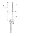
- FIG. 5 is a view showing an example of a cobra antenna produced by modifying a dipole antenna.
- a wavelength of a received radio wave is ⁇
- a central conductor (core wire) 300 having a length of ⁇ / 4 is connected to the upper side from the feeding point 200 as an upper element.
- a ferrite core 400 is also provided on the lower side from the feeding point 200 and also provided at a distance of ⁇ / 4.
- a coaxial cable (coaxial line) 500 is wound around the ferrite core 400.
- the number of windings (the number of windings) of the coaxial cable 500 is three, but the number of windings does not have to be three and may be one or two.
- the impedance tends to rapidly decrease from around 100 MHz regardless of the size of the ferrite.
- the impedance of the antenna tends to increase even if the frequency exceeds 100 MHz, but when the number of turns is three, it is reported that the impedance decreases rapidly.
- a choke coil is formed by the ferrite core 300 and the coaxial cable 500 wound around the ferrite core 300, and the lower feeder portion is separated from the ferrite core 400, so that a ⁇ / 4 dipole antenna can be easily formed.
- the antenna By attaching an egg glass or the like to the core wire 300 on the upper side of the dipole antenna to insulate it and suspending it on a tree branch or tree frame, the antenna can be easily installed.
- the cobra antenna configured as described above can be used as an antenna of a mobile device such as an automobile.
- radio wave interference may occur due to the length of the coaxial cable 500 from the ferrite core 400 to the receiver. is there. That is, there is a problem of radio wave interference in which high-frequency current received by the upper coaxial cable 500 extending from the ferrite core 400 to the feeding point 200 leaks from the ferrite core 400 to the lower coaxial cable 500 connected to the receiver. appear.
- the leakage of the high-frequency current is considered to occur due to impedance mismatch between the upper side and the lower side of the ferrite core 400.
- the leakage causes a disadvantage that the gain characteristic as an antenna is deteriorated.
- the occurrence of leakage of the high-frequency current depends on the length of the coaxial cable 500 that is connected from the ferrite core 400 to the receiver. That is, in the conventional cobra antenna 100, the length of the coaxial cable 500 from the ferrite 400 to the receiver cannot be determined freely. This high-frequency current interference is considered to occur because the Cobra antenna 100 uses the outer skin of the coaxial cable 500 as an antenna. For this reason, there is a problem in that the required performance cannot be obtained even if the cobra antenna 100 is directly connected to the connector of the receiver.
- the present invention has been made in view of the above problems, and can be used as an antenna in a wide frequency band from the FM band to the UHF band, is small in size, has excellent antenna performance, and has a coaxial line length.
- An object of the present invention is to provide a cobra antenna with minimal restrictions.
- the cobra antenna of the present invention is provided with a relay unit that constitutes a feeding point, and one terminal of this relay unit corresponds to the frequency of the broadcast wave to be received.
- Antenna elements having different lengths are electrically connected.
- a coaxial line is connected to the other terminal of the relay unit, and the coaxial line is wound about 1 to 3 times at a position separated from the other terminal of the relay unit to which the coaxial line is connected by the same length as the antenna element.
- a rotated ferrite core is arranged.
- a high-frequency cutoff unit for blocking high-frequency current from the coaxial line is provided on the front side of the connector of the receiving device to which the other end of the coaxial line is connected.
- the high-frequency cutoff unit is a second ferrite core having high impedance in terms of high frequency and having the coaxial line penetrated or wound therein. Further, the length of the antenna element and the length from the coaxial line relay section to the ferrite core are ⁇ / 4, where ⁇ is the wavelength of the frequency to be received.
- the high frequency picked up by the coaxial line can be prevented from entering the receiving device by providing the second ferrite core having a high impedance with respect to the high frequency before the connector of the receiving device. .
- the length of the coaxial line other than the antenna line can be freely determined, so that restrictions on arranging the antenna can be reduced. Therefore, the cobra antenna of the present invention can sufficiently exhibit the performance as an antenna regardless of the connected device and irrespective of the length of the coaxial line of the antenna.
- a in FIG. 1 is the same as the conventional cobra antenna described in FIG. 5, and B in FIG. 1 shows the cobra antenna of this example.
- a cobra antenna 10 shown in FIGS. 1A and 1B includes an antenna element 2 having a length of ⁇ / 4, a wavelength of a received radio wave, a relay portion 3 as a feed point, a coaxial line 5, a ferrite A core 4 is provided.
- the length of the coaxial line from the relay unit 3 to the ferrite core 4 is ⁇ / 4, which is the same as that of the antenna element 2.
- the coaxial line 5 is connected to the antenna element 2 by the relay unit 3.
- the coaxial line 5 is wound around the ferrite core 4 about 1 to 3 times, and the other end is connected to the connector 6 of the receiver 8.
- the connector 6 it is desirable to select one having a low loss of high-frequency signals.
- the antenna element 2 is obtained by removing the outer sheath (protective coating) 5a and the shield wire (outer conductor) 5b of the coaxial line 5.
- the relay portion 3 the outer sheath 5a and the shield wire 5b of the coaxial line 5 are removed, and the core material 2c (derivative) is exposed.
- the core wire 5 d of the coaxial wire 5 is connected to the core wire of the antenna element 2 by soldering or the like, and the relay portion 3 is molded on the substrate 7.
- This relay unit 3 becomes a feeding point Fp of the cobra antenna 10.
- a dipole antenna of ⁇ / 2 is formed by the coaxial line 5 (length ⁇ / 4) and the antenna element 2 (length ⁇ / 4) from the relay unit 3 (feeding point) to the ferrite core 4.
- the coaxial line 5 length ⁇ / 4
- the antenna element 2 length ⁇ / 4
- the conventional cobra antenna shown in FIG. 1A is called a cobra antenna (one core product), and the cobra antenna of the present invention is called a cobra antenna (two core products).
- the conventional cobra antenna (one core product) as already described, high-frequency coupling between the coaxial wire 5 from the ferrite core 4 to the relay portion 3 and the coaxial wire 5 from the ferrite core 4 to the connector 6 occurs, The antenna performance is degraded. Since this depends on the length from the ferrite core 4 to the coaxial line 5 from the connector 6, when this type of cobra antenna is used as a vehicle-mounted antenna, the length of this portion is restricted.
- a second ferrite core 4a is provided at a position close to the receiver 8, and this ferrite core 4a has a high impedance with respect to a high frequency. As a result, the high-frequency current leaking from the antenna does not propagate to the receiver side.
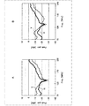
- FIG. 2A and Table 1 are graphs showing peak gains in the vertical polarization (V) and horizontal polarization (H) of the conventional cobra antenna (one core product) shown in FIG. 1A.
- the horizontal axis of A in FIG. 2 indicates the frequency (MHz), and the vertical axis indicates the peak gain (dBd).
- the frequency band to be measured is FM / VHF band (70 MHz to 220 MHz), vertical polarization (V) is indicated by a broken line, and horizontal polarization (H) is indicated by a solid line.
- Table 1 shows the peak gain value in the vertical polarization (V) and the peak gain value in the horizontal polarization (H) at each measurement point in the graph shown in FIG. In Table 1, only measured values at frequencies between 76 MHz and 107 MHz among the frequencies shown on the horizontal axis of A in FIG. 2 are shown.
- the peak gain at vertical polarization (V) is ⁇ 11.50 dBd at 86 MHz and ⁇ 10.85 dBd at 95 MHz.
- the peak gain in horizontal polarization (H) is -16.70 dBd at 86 MHz, and -14.85 dBd at 95 MHz. That is, it can be seen that even a conventional cobra antenna (one core product) can receive both vertically polarized waves and horizontally polarized waves in the FM / VHF band.
- the frequency gain characteristics of the cobra antenna (two core products) of this example are as shown in FIG.
- both vertical polarization (V) and horizontal polarization (H) show maximum values in the vicinity of 95 MHz
- vertical polarization (V) is ⁇ 8.25 dBd, horizontal polarization. In (H), it is -13.65 dBd.
- the peak gain at 95 MHz is higher, and the frequency-gain characteristic is clearly improved. That is, it can be seen that the performance of the cobra antenna (two core products) of this example is better than the conventional cobra antenna (single core product).
- the minimum value is shown around 130 MHz. This indicates that since the resonance frequency is set to 100 MHz, the Q value of the antenna becomes high near 130 MHz, resulting in antiresonance (mismatch), and reception is not possible. Note that when the resonance frequency is adjusted to 100 MHz, resonance occurs in higher harmonics, so that even odd-numbered times, that is, 3 times and 5 times the fundamental resonance wavelength can be received.
- the cobra antenna (two core products) of this example is designed to resonate even at 200 MHz.
- FIG. 3 is a diagram showing an example in which a cobra antenna (two core products) is mounted on a car owned by the inventor in order to perform a field test of the cobra antenna (two core products) of this example. Needless to say, for comparison, a conventional cobra antenna (one core product) is mounted and the same measurement is performed.
- the antenna element 2 ahead of the relay part 3 of the cobra antenna 10 is attached to the windshield horizontally from the rearview mirror, and the coaxial line 5 from the relay part 3 to the ferrite core 4 is vertically oriented on the left side. Attached.
- the cobra antenna 10 is configured as a V-shaped antenna with the relay unit 3 being a feeding point as the center (starting point).
- both the cobra antenna (two core products) and the conventional cobra antenna (one core product) have a wavelength ⁇ of 90 MHz in the FM band of 3.33 m, so the length of the antenna element 2 is 0.83 m of ⁇ / 4.
- the length of the coaxial line 5 from the relay unit 3 to the ferrite core 4 is also 0.83 m of ⁇ / 4, and the length of the antenna is ⁇ / 2 (1.66 m).
- the coaxial line 5 from the ferrite core 4 to the connector 6 of the receiver 8 runs horizontally on the dashboard of the car.
- the second ferrite core 4 a is inserted in front of (in the vicinity of) the connector 6 of the receiver 8.
- the coaxial wire 5 may be simply passed through the hole of the second ferrite core 4a, but the coaxial wire 5 may be wound around the ferrite core 4a about once to three times and then connected to the connector 6.
- the ferrite core 4 a is arranged in front of the connector 6, so that the coaxial line 5 connecting the ferrite core 4 and the connector 6 can detect the high frequency current.
- the receiver 8 side has a high impedance. For this reason, even if the high frequency current leaked from the coaxial line 5 from the first ferrite core 4 to the connector 6 is picked up, the leaked high frequency current does not adversely affect the receiver 8 side.
- FIG. 4 shows a course in which the inventor actually installed a cobra antenna in a private car and tested its reception performance.
- the model used is Toyota Corolla (registered trademark)
- the equipment used as the receiver 8 is PND (personal navigation device) (GORILLA NV-SD750FT) (GORILLA is a registered trademark) manufactured by Sanyo Electric Co., Ltd.
- the received frequency is 81.9 MHz of VICS Yokohama and the output is 5 kW.
- the distance from the relay part 3 to the tip of the antenna element 2 was 83 cm, and the distance from the relay part 3 to the ferrite core 4 was also 83 cm.
- the second ferrite core 4a is provided at a position about 5 cm away from the plug inserted into the connector 6 of the receiver 8, but this distance can be determined as appropriate.
- a conventional cobra antenna (one core product) is first installed, the vehicle runs on the Nakahara Kaido shown in the figure, and the VICS supplement is updated every 5 minutes in the travel section. Went. Subsequently, the same course was loaded with the cobra antenna (two core products) of this example, and VICS supplementation of the traveling section was similarly performed every 5 minutes.
- test results were as follows. Conventional cobra antenna (1 core product) 6/11 times Reception rate 54% Cobra antenna of this example (2 core products) 12/14 times Reception rate 78% As is apparent from this result, the data of the cobra antenna (two core products) of this example can be updated almost certainly every 5 minutes compared to the conventional type (one core product). It could be confirmed.
- the cobra antenna two core products
- the conventional cobra antenna one core product
- an antenna using a coaxial line wire material
- the same effect can be exhibited even if an antenna made of a substrate, a film, or a metal wire is used for the antenna element portion.
- the example in which the vehicle is mounted on a car has been described.
Landscapes
- Engineering & Computer Science (AREA)
- Remote Sensing (AREA)
- Details Of Aerials (AREA)
Abstract
Priority Applications (5)
| Application Number | Priority Date | Filing Date | Title |
|---|---|---|---|
| BR112012023709A BR112012023709A2 (pt) | 2010-03-26 | 2011-03-14 | antena cobra |
| KR1020127024374A KR101660084B1 (ko) | 2010-03-26 | 2011-03-14 | 코브라 안테나 |
| EP11759242A EP2555325A1 (fr) | 2010-03-26 | 2011-03-14 | Antenne cobra |
| US13/635,933 US9837708B2 (en) | 2010-03-26 | 2011-03-14 | Cobra antenna |
| CN201180014782.9A CN102804500B (zh) | 2010-03-26 | 2011-03-14 | 眼镜蛇天线 |
Applications Claiming Priority (2)
| Application Number | Priority Date | Filing Date | Title |
|---|---|---|---|
| JP2010-071218 | 2010-03-26 | ||
| JP2010071218A JP5600987B2 (ja) | 2010-03-26 | 2010-03-26 | コブラアンテナ |
Publications (1)
| Publication Number | Publication Date |
|---|---|
| WO2011118436A1 true WO2011118436A1 (fr) | 2011-09-29 |
Family
ID=44672993
Family Applications (1)
| Application Number | Title | Priority Date | Filing Date |
|---|---|---|---|
| PCT/JP2011/055924 Ceased WO2011118436A1 (fr) | 2010-03-26 | 2011-03-14 | Antenne cobra |
Country Status (8)
| Country | Link |
|---|---|
| US (1) | US9837708B2 (fr) |
| EP (1) | EP2555325A1 (fr) |
| JP (1) | JP5600987B2 (fr) |
| KR (1) | KR101660084B1 (fr) |
| CN (1) | CN102804500B (fr) |
| BR (1) | BR112012023709A2 (fr) |
| TW (1) | TWI478444B (fr) |
| WO (1) | WO2011118436A1 (fr) |
Cited By (3)
| Publication number | Priority date | Publication date | Assignee | Title |
|---|---|---|---|---|
| EP2800204A4 (fr) * | 2011-12-28 | 2015-09-09 | Sony Corp | Dispositif d'antenne |
| CN105552531A (zh) * | 2016-01-16 | 2016-05-04 | 昆山联滔电子有限公司 | 偶极天线 |
| JP2022051497A (ja) * | 2020-09-18 | 2022-03-31 | サン電子株式会社 | 防災無線の戸別受信機用アンテナ |
Families Citing this family (8)
| Publication number | Priority date | Publication date | Assignee | Title |
|---|---|---|---|---|
| JP5444786B2 (ja) | 2009-03-30 | 2014-03-19 | ソニー株式会社 | 受信装置 |
| BR112015000239A8 (pt) | 2012-07-13 | 2019-07-16 | Sony Corp | antena |
| US9812754B2 (en) * | 2015-02-27 | 2017-11-07 | Harris Corporation | Devices with S-shaped balun segment and related methods |
| US10522914B2 (en) * | 2015-12-28 | 2019-12-31 | The Board Of Trustees Of The University Of Alabama | Patch antenna with ferrite cores |
| EP3439187B1 (fr) | 2016-03-29 | 2020-05-13 | Sony Corporation | Récepteur, et dispositif de fourniture de signal rf |
| KR102488640B1 (ko) * | 2018-01-30 | 2023-01-16 | 삼성전자주식회사 | Usb 커넥터를 이용하여 안테나 기능을 수행하기 위한 장치 및 방법 |
| US11063345B2 (en) * | 2018-07-17 | 2021-07-13 | Mastodon Design Llc | Systems and methods for providing a wearable antenna |
| KR102543391B1 (ko) | 2021-08-27 | 2023-06-13 | 도아섭 | 조립식 수레 적재판과 그 적재판의 모서리연결구 |
Citations (4)
| Publication number | Priority date | Publication date | Assignee | Title |
|---|---|---|---|---|
| JPS60254901A (ja) * | 1984-05-31 | 1985-12-16 | Antenna Giken Kk | アンテナ装置 |
| JPS6333205U (fr) * | 1986-08-21 | 1988-03-03 | ||
| JP2002517924A (ja) * | 1998-05-29 | 2002-06-18 | テレフオンアクチーボラゲット エル エム エリクソン(パブル) | 無線通信機器用高能率マルチバンドアンテナ |
| WO2007017959A1 (fr) * | 2005-08-08 | 2007-02-15 | Murata Manufacturing Co., Ltd. | Oscillateur de référence |
Family Cites Families (11)
| Publication number | Priority date | Publication date | Assignee | Title |
|---|---|---|---|---|
| US3534371A (en) * | 1968-07-10 | 1970-10-13 | Adams Russel Co Inc | Plural dipole vertical antenna with isolation chokes |
| JPS6126794U (ja) | 1984-07-23 | 1986-02-18 | 三和機材株式会社 | 埋設管推進装置 |
| US4730195A (en) * | 1985-07-01 | 1988-03-08 | Motorola, Inc. | Shortened wideband decoupled sleeve dipole antenna |
| JP2581834B2 (ja) * | 1990-09-12 | 1997-02-12 | 三菱電機株式会社 | アンテナ装置 |
| JPH11274840A (ja) * | 1998-03-23 | 1999-10-08 | Sony Corp | アンテナ装置 |
| JP4210016B2 (ja) * | 2000-04-04 | 2009-01-14 | Necトーキン株式会社 | 通信ケーブル |
| WO2010008269A1 (fr) * | 2008-07-14 | 2010-01-21 | Laird Technologies, Inc. | Ensembles antennes à bandes multiples pour une utilisation avec des dispositifs d'application sans fil |
| JP2010057007A (ja) * | 2008-08-29 | 2010-03-11 | Dx Antenna Co Ltd | アンテナ |
| JP5018946B2 (ja) * | 2009-10-13 | 2012-09-05 | ソニー株式会社 | アンテナ |
| KR20130070589A (ko) * | 2010-05-11 | 2013-06-27 | 소니 주식회사 | 코브라 안테나 |
| US8593363B2 (en) * | 2011-01-27 | 2013-11-26 | Tdk Corporation | End-fed sleeve dipole antenna comprising a ¾-wave transformer |
-
2010
- 2010-03-26 JP JP2010071218A patent/JP5600987B2/ja not_active Expired - Fee Related
-
2011
- 2011-03-10 TW TW100108099A patent/TWI478444B/zh not_active IP Right Cessation
- 2011-03-14 US US13/635,933 patent/US9837708B2/en not_active Expired - Fee Related
- 2011-03-14 CN CN201180014782.9A patent/CN102804500B/zh not_active Expired - Fee Related
- 2011-03-14 BR BR112012023709A patent/BR112012023709A2/pt not_active IP Right Cessation
- 2011-03-14 WO PCT/JP2011/055924 patent/WO2011118436A1/fr not_active Ceased
- 2011-03-14 KR KR1020127024374A patent/KR101660084B1/ko not_active Expired - Fee Related
- 2011-03-14 EP EP11759242A patent/EP2555325A1/fr not_active Withdrawn
Patent Citations (4)
| Publication number | Priority date | Publication date | Assignee | Title |
|---|---|---|---|---|
| JPS60254901A (ja) * | 1984-05-31 | 1985-12-16 | Antenna Giken Kk | アンテナ装置 |
| JPS6333205U (fr) * | 1986-08-21 | 1988-03-03 | ||
| JP2002517924A (ja) * | 1998-05-29 | 2002-06-18 | テレフオンアクチーボラゲット エル エム エリクソン(パブル) | 無線通信機器用高能率マルチバンドアンテナ |
| WO2007017959A1 (fr) * | 2005-08-08 | 2007-02-15 | Murata Manufacturing Co., Ltd. | Oscillateur de référence |
Non-Patent Citations (1)
| Title |
|---|
| "WIRE ANTENNA", article "ANTENA NO KISO", pages: 84 |
Cited By (5)
| Publication number | Priority date | Publication date | Assignee | Title |
|---|---|---|---|---|
| EP2800204A4 (fr) * | 2011-12-28 | 2015-09-09 | Sony Corp | Dispositif d'antenne |
| US9786983B2 (en) | 2011-12-28 | 2017-10-10 | Sony Corporation | Antenna device |
| CN105552531A (zh) * | 2016-01-16 | 2016-05-04 | 昆山联滔电子有限公司 | 偶极天线 |
| JP2022051497A (ja) * | 2020-09-18 | 2022-03-31 | サン電子株式会社 | 防災無線の戸別受信機用アンテナ |
| JP7539012B2 (ja) | 2020-09-18 | 2024-08-23 | サン電子株式会社 | 防災無線の戸別受信機用アンテナ |
Also Published As
| Publication number | Publication date |
|---|---|
| JP5600987B2 (ja) | 2014-10-08 |
| KR20130010890A (ko) | 2013-01-29 |
| CN102804500B (zh) | 2016-02-10 |
| JP2011205437A (ja) | 2011-10-13 |
| US20130009835A1 (en) | 2013-01-10 |
| TWI478444B (zh) | 2015-03-21 |
| CN102804500A (zh) | 2012-11-28 |
| US9837708B2 (en) | 2017-12-05 |
| BR112012023709A2 (pt) | 2016-08-23 |
| KR101660084B1 (ko) | 2016-09-26 |
| EP2555325A1 (fr) | 2013-02-06 |
| TW201210137A (en) | 2012-03-01 |
Similar Documents
| Publication | Publication Date | Title |
|---|---|---|
| JP5600987B2 (ja) | コブラアンテナ | |
| US20130050042A1 (en) | Cobra antenna | |
| EP2490295B1 (fr) | Antenne | |
| WO2010134538A1 (fr) | Dispositif d'antenne | |
| US7446719B2 (en) | Mobile antenna mounted on a vehicle body | |
| CN106207410A (zh) | 一种vhf/uhf双频段宽带复合天线 | |
| US20180069290A1 (en) | Glass antenna | |
| JP6492578B2 (ja) | 車両用ガラスアンテナ及び車両用窓ガラス | |
| JP5493727B2 (ja) | ガラスアンテナ用フィルタ装置及び車両用窓ガラス | |
| US10290928B2 (en) | Antenna | |
| WO2012121015A1 (fr) | Antenne | |
| JP2009065359A (ja) | 車両用ガラスアンテナ | |
| JPH11206012A (ja) | 雷サージ保護回路 | |
| JP5648653B2 (ja) | アンテナ | |
| US9219315B2 (en) | Combination antenna | |
| JP5521391B2 (ja) | アンテナ装置 | |
| JP2534005B2 (ja) | 移動体用アンテナ装置 |
Legal Events
| Date | Code | Title | Description |
|---|---|---|---|
| WWE | Wipo information: entry into national phase |
Ref document number: 201180014782.9 Country of ref document: CN |
|
| 121 | Ep: the epo has been informed by wipo that ep was designated in this application |
Ref document number: 11759242 Country of ref document: EP Kind code of ref document: A1 |
|
| REEP | Request for entry into the european phase |
Ref document number: 2011759242 Country of ref document: EP |
|
| WWE | Wipo information: entry into national phase |
Ref document number: 2011759242 Country of ref document: EP |
|
| ENP | Entry into the national phase |
Ref document number: 20127024374 Country of ref document: KR Kind code of ref document: A |
|
| WWE | Wipo information: entry into national phase |
Ref document number: 13635933 Country of ref document: US Ref document number: 8179/DELNP/2012 Country of ref document: IN |
|
| NENP | Non-entry into the national phase |
Ref country code: DE |
|
| REG | Reference to national code |
Ref country code: BR Ref legal event code: B01A Ref document number: 112012023709 Country of ref document: BR |
|
| ENP | Entry into the national phase |
Ref document number: 112012023709 Country of ref document: BR Kind code of ref document: A2 Effective date: 20120919 |