WO2011122146A1 - Compresseur - Google Patents
Compresseur Download PDFInfo
- Publication number
- WO2011122146A1 WO2011122146A1 PCT/JP2011/053362 JP2011053362W WO2011122146A1 WO 2011122146 A1 WO2011122146 A1 WO 2011122146A1 JP 2011053362 W JP2011053362 W JP 2011053362W WO 2011122146 A1 WO2011122146 A1 WO 2011122146A1
- Authority
- WO
- WIPO (PCT)
- Prior art keywords
- housing
- lip seal
- seal device
- rotating shaft
- compressor
- Prior art date
- Legal status (The legal status is an assumption and is not a legal conclusion. Google has not performed a legal analysis and makes no representation as to the accuracy of the status listed.)
- Ceased
Links
Images

Classifications
-
- F—MECHANICAL ENGINEERING; LIGHTING; HEATING; WEAPONS; BLASTING
- F04—POSITIVE - DISPLACEMENT MACHINES FOR LIQUIDS; PUMPS FOR LIQUIDS OR ELASTIC FLUIDS
- F04B—POSITIVE-DISPLACEMENT MACHINES FOR LIQUIDS; PUMPS
- F04B39/00—Component parts, details, or accessories, of pumps or pumping systems specially adapted for elastic fluids, not otherwise provided for in, or of interest apart from, groups F04B25/00 - F04B37/00
- F04B39/12—Casings; Cylinders; Cylinder heads; Fluid connections
- F04B39/121—Casings
-
- F—MECHANICAL ENGINEERING; LIGHTING; HEATING; WEAPONS; BLASTING
- F01—MACHINES OR ENGINES IN GENERAL; ENGINE PLANTS IN GENERAL; STEAM ENGINES
- F01C—ROTARY-PISTON OR OSCILLATING-PISTON MACHINES OR ENGINES
- F01C19/00—Sealing arrangements in rotary-piston machines or engines
- F01C19/005—Structure and composition of sealing elements such as sealing strips, sealing rings and the like; Coating of these elements
-
- F—MECHANICAL ENGINEERING; LIGHTING; HEATING; WEAPONS; BLASTING
- F01—MACHINES OR ENGINES IN GENERAL; ENGINE PLANTS IN GENERAL; STEAM ENGINES
- F01C—ROTARY-PISTON OR OSCILLATING-PISTON MACHINES OR ENGINES
- F01C21/00—Component parts, details or accessories not provided for in groups F01C1/00 - F01C20/00
- F01C21/10—Outer members for co-operation with rotary pistons; Casings
-
- F—MECHANICAL ENGINEERING; LIGHTING; HEATING; WEAPONS; BLASTING
- F04—POSITIVE - DISPLACEMENT MACHINES FOR LIQUIDS; PUMPS FOR LIQUIDS OR ELASTIC FLUIDS
- F04B—POSITIVE-DISPLACEMENT MACHINES FOR LIQUIDS; PUMPS
- F04B27/00—Multi-cylinder pumps specially adapted for elastic fluids and characterised by number or arrangement of cylinders
- F04B27/08—Multi-cylinder pumps specially adapted for elastic fluids and characterised by number or arrangement of cylinders having cylinders coaxial with, or parallel or inclined to, main shaft axis
- F04B27/0804—Multi-cylinder pumps specially adapted for elastic fluids and characterised by number or arrangement of cylinders having cylinders coaxial with, or parallel or inclined to, main shaft axis having rotary cylinder block
- F04B27/0821—Multi-cylinder pumps specially adapted for elastic fluids and characterised by number or arrangement of cylinders having cylinders coaxial with, or parallel or inclined to, main shaft axis having rotary cylinder block component parts, details, e.g. valves, sealings, lubrication
-
- F—MECHANICAL ENGINEERING; LIGHTING; HEATING; WEAPONS; BLASTING
- F04—POSITIVE - DISPLACEMENT MACHINES FOR LIQUIDS; PUMPS FOR LIQUIDS OR ELASTIC FLUIDS
- F04B—POSITIVE-DISPLACEMENT MACHINES FOR LIQUIDS; PUMPS
- F04B39/00—Component parts, details, or accessories, of pumps or pumping systems specially adapted for elastic fluids, not otherwise provided for in, or of interest apart from, groups F04B25/00 - F04B37/00
- F04B39/04—Measures to avoid lubricant contaminating the pumped fluid
-
- F—MECHANICAL ENGINEERING; LIGHTING; HEATING; WEAPONS; BLASTING
- F04—POSITIVE - DISPLACEMENT MACHINES FOR LIQUIDS; PUMPS FOR LIQUIDS OR ELASTIC FLUIDS
- F04C—ROTARY-PISTON, OR OSCILLATING-PISTON, POSITIVE-DISPLACEMENT MACHINES FOR LIQUIDS; ROTARY-PISTON, OR OSCILLATING-PISTON, POSITIVE-DISPLACEMENT PUMPS
- F04C18/00—Rotary-piston pumps specially adapted for elastic fluids
- F04C18/02—Rotary-piston pumps specially adapted for elastic fluids of arcuate-engagement type, i.e. with circular translatory movement of co-operating members, each member having the same number of teeth or tooth-equivalents
- F04C18/0207—Rotary-piston pumps specially adapted for elastic fluids of arcuate-engagement type, i.e. with circular translatory movement of co-operating members, each member having the same number of teeth or tooth-equivalents both members having co-operating elements in spiral form
- F04C18/0215—Rotary-piston pumps specially adapted for elastic fluids of arcuate-engagement type, i.e. with circular translatory movement of co-operating members, each member having the same number of teeth or tooth-equivalents both members having co-operating elements in spiral form where only one member is moving
-
- F—MECHANICAL ENGINEERING; LIGHTING; HEATING; WEAPONS; BLASTING
- F04—POSITIVE - DISPLACEMENT MACHINES FOR LIQUIDS; PUMPS FOR LIQUIDS OR ELASTIC FLUIDS
- F04C—ROTARY-PISTON, OR OSCILLATING-PISTON, POSITIVE-DISPLACEMENT MACHINES FOR LIQUIDS; ROTARY-PISTON, OR OSCILLATING-PISTON, POSITIVE-DISPLACEMENT PUMPS
- F04C27/00—Sealing arrangements in rotary-piston pumps specially adapted for elastic fluids
- F04C27/008—Sealing arrangements in rotary-piston pumps specially adapted for elastic fluids for other than working fluid, i.e. the sealing arrangements are not between working chambers of the machine
- F04C27/009—Shaft sealings specially adapted for pumps
-
- F—MECHANICAL ENGINEERING; LIGHTING; HEATING; WEAPONS; BLASTING
- F04—POSITIVE - DISPLACEMENT MACHINES FOR LIQUIDS; PUMPS FOR LIQUIDS OR ELASTIC FLUIDS
- F04C—ROTARY-PISTON, OR OSCILLATING-PISTON, POSITIVE-DISPLACEMENT MACHINES FOR LIQUIDS; ROTARY-PISTON, OR OSCILLATING-PISTON, POSITIVE-DISPLACEMENT PUMPS
- F04C18/00—Rotary-piston pumps specially adapted for elastic fluids
- F04C18/02—Rotary-piston pumps specially adapted for elastic fluids of arcuate-engagement type, i.e. with circular translatory movement of co-operating members, each member having the same number of teeth or tooth-equivalents
- F04C18/0207—Rotary-piston pumps specially adapted for elastic fluids of arcuate-engagement type, i.e. with circular translatory movement of co-operating members, each member having the same number of teeth or tooth-equivalents both members having co-operating elements in spiral form
- F04C18/0246—Details concerning the involute wraps or their base, e.g. geometry
-
- F—MECHANICAL ENGINEERING; LIGHTING; HEATING; WEAPONS; BLASTING
- F04—POSITIVE - DISPLACEMENT MACHINES FOR LIQUIDS; PUMPS FOR LIQUIDS OR ELASTIC FLUIDS
- F04C—ROTARY-PISTON, OR OSCILLATING-PISTON, POSITIVE-DISPLACEMENT MACHINES FOR LIQUIDS; ROTARY-PISTON, OR OSCILLATING-PISTON, POSITIVE-DISPLACEMENT PUMPS
- F04C2240/00—Components
- F04C2240/30—Casings or housings
-
- F—MECHANICAL ENGINEERING; LIGHTING; HEATING; WEAPONS; BLASTING
- F04—POSITIVE - DISPLACEMENT MACHINES FOR LIQUIDS; PUMPS FOR LIQUIDS OR ELASTIC FLUIDS
- F04C—ROTARY-PISTON, OR OSCILLATING-PISTON, POSITIVE-DISPLACEMENT MACHINES FOR LIQUIDS; ROTARY-PISTON, OR OSCILLATING-PISTON, POSITIVE-DISPLACEMENT PUMPS
- F04C28/00—Control of, monitoring of, or safety arrangements for, pumps or pumping installations specially adapted for elastic fluids
- F04C28/28—Safety arrangements; Monitoring
-
- F—MECHANICAL ENGINEERING; LIGHTING; HEATING; WEAPONS; BLASTING
- F04—POSITIVE - DISPLACEMENT MACHINES FOR LIQUIDS; PUMPS FOR LIQUIDS OR ELASTIC FLUIDS
- F04C—ROTARY-PISTON, OR OSCILLATING-PISTON, POSITIVE-DISPLACEMENT MACHINES FOR LIQUIDS; ROTARY-PISTON, OR OSCILLATING-PISTON, POSITIVE-DISPLACEMENT PUMPS
- F04C29/00—Component parts, details or accessories of pumps or pumping installations, not provided for in groups F04C18/00 - F04C28/00
- F04C29/0042—Driving elements, brakes, couplings, transmissions specially adapted for pumps
- F04C29/005—Means for transmitting movement from the prime mover to driven parts of the pump, e.g. clutches, couplings, transmissions
Definitions
- the present invention relates to a compressor provided with a lip seal device at a shaft seal portion.
- a compressor in which a compression mechanism is provided inside a housing, and a so-called open type compressor in which one end of a rotating shaft coupled to the compression mechanism protrudes outside through the housing.
- the penetrating portion of the rotating shaft is sealed so that the gas flowing through the shaft does not leak out from the penetrating portion of the rotating shaft.
- a lip seal device has been used for the shaft seal.
- the lip seal device has a structure in which an annular main lip seal material, a sub lip seal material, and the like made of an elastically deformable rubber material are provided on the inner and outer circumferences of a highly rigid metal annular shape retaining material, Press fit the outer peripheral part of the main lip seal material corresponding to the annular shape retaining material into the lip seal housing part on the housing side, and press the lip part of the main lip seal material and the sub lip seal material into the outer periphery of the rotating shaft for assembly. As a result, the penetrating portion of the rotating shaft was sealed.
- Patent Document 1 proposes a seal structure provided with an engaging protrusion engaged with the elastically deformable annular groove located on the front side or the rear side thereof.
- a lip seal device is press-fitted toward the flange portion from the inside of the housing, and an engagement protrusion provided on the outer peripheral portion of the main lip seal material is engaged with the annular groove.
- the lip seal device is prevented from coming off, and the lip seal device can be assembled without using a snap ring or the like, so that the ease of assembly can be secured.
- the present invention has been made to solve the above-described problem, and is a compressor capable of easily reducing the risk of gas leakage by making the lip seal device difficult to tilt while maintaining ease of assembly.
- the purpose is to provide.
- a compressor according to the present invention includes a housing having a space therein, a compression mechanism that is disposed in the housing and compresses a fluid taken into the space, and a rotary shaft that drives the compression mechanism, One end portion of the rotating shaft penetrates the housing and protrudes to the outside, and the penetrating portion of the housing is shaft-sealed by a lip seal device.
- the compressor constitutes the lip seal device, and the rotating shaft A flat surface in contact with the entire flat outer peripheral surface of the ring portion of the main lip seal member extending along the axial direction of the main lip seal material, and located on the inner side of the housing with respect to the flat surface and orthogonal to the axial direction of the rotating shaft A first vertical retaining surface extending radially inward along the direction, and positioned on the outer side of the housing with respect to the flat surface, along a direction orthogonal to the axial direction of the rotary shaft Lip seal device accommodation portion formed by a second stopper for the vertical plane extending radially inward is provided in the through portion.
- the lip seal device is assembled to the penetrating portion of the housing without using a snap ring or the like, the ease of assembly can be maintained.
- the lip seal device since the entire flat outer peripheral surface of the ring portion comes into contact with the flat surface of the lip seal device housing portion, the lip seal device is hardly tilted, and the risk of gas leakage can be easily reduced.
- the depth of the first retaining vertical surface is set to a depth corresponding to 8% to 40% of the thickness of the ring portion.
- the compressor according to the present invention produces an effect that the lip seal device is not easily tilted while maintaining ease of assembly, and the risk of gas leakage can be easily reduced.
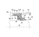
- FIG. 1 is a longitudinal sectional view of a scroll compressor according to the present embodiment
- FIG. 2 is an enlarged view of a main part of the main part of FIG.
- the scroll compressor 10 includes a housing 11 having a sealed space m therein, and a refrigerant gas (fluid) disposed in the housing 11 and taken into the sealed space m.
- the main components are a scroll compression mechanism 12 that compresses the scroll compression mechanism 12, a rotary shaft 13 that drives the scroll compression mechanism 12, and a drive unit that drives the scroll compression mechanism 12 to revolve.
- the housing 11 includes a front housing 14 and a rear housing 15, which are combined together and then coupled with a plurality of bolts (not shown), thereby forming a sealed space m therein.
- Reference numeral 16 denotes a single O-ring that seals the joint between the front housing 14 and the rear housing 15 to keep the sealed space m sealed.
- a thrust plate 14a that matches the end surface is provided on the end surface of the front housing 14, and a hole (notch) (not shown) corresponding to a receiving portion 38 described later is formed in the thrust plate 14a.
- a suction port (not shown) for sucking refrigerant gas is formed on the front side of the rear housing 15 so as to communicate with the sealed space m.
- a scroll compression mechanism is provided on the upper rear side of the rear housing 15. 12, a discharge port 15a is formed through which compressed refrigerant gas is discharged after the lubricating oil in the refrigerant gas is separated by an oil separation chamber (not shown).
- an oil reservoir chamber 18 oil storage portion that stores the lubricating oil separated by the oil separation chamber is formed on the discharge side (high pressure side) of the rear housing 15.
- the oil separation chamber only needs to have an oil separation function, such as a centrifugal separation type, so long as the separated oil is led to the oil reservoir chamber 18.
- the scroll compression mechanism 12 includes a fixed scroll 21 and a turning scroll 22.
- the fixed scroll 21 includes a fixed end plate 21a and a spiral wall body 21b erected on the inner surface thereof, and a discharge port 21c is formed at the center of the fixed end plate 21a.
- the discharge port 21c is opened and closed by a discharge valve (not shown) attached to the rear surface (back surface) of the fixed end plate 21a via a bolt (not shown).
- a communication path (lubricating oil path) 23 that connects the bottom of the oil reservoir 18 and the suction side bottom of the sealed space m is formed at the lower end of the fixed scroll 21.
- the filter 24 and the spiral pin 25 for flow rate adjustment are arranged from the upstream side.
- the communication passage 23 communicates the oil reservoir chamber 18 provided on the high pressure side in the scroll compressor 10 and the low pressure side, and further has a large diameter having substantially the same inner diameter as the outer diameter of the spiral pin 25.
- Portion) 23b is formed in the order of the large diameter portion 23a and the small diameter portion 23b from the upstream side (oil reservoir chamber 18 side).
- the spiral pin 25 is a member having a substantially cylindrical shape, and both end portions are formed with tapered portions 25a, and a spiral groove (hereinafter, “ 25c ”(referred to as“ spiral groove ”).
- the spiral pin 25 is disposed on the upstream side (the oil reservoir chamber 18 side) in the large diameter portion 23a.
- the lubricating oil that has passed through the filter 24 once flows out into the large diameter portion 23a located on the downstream side of the spiral pin 25 through the spiral groove 25c, and then flows out to the suction side bottom of the sealed space m through the small diameter portion 23b. (Squirting).
- the throttle portion 23b has an end opening 23c of the communication passage 23 that opens to the orbiting scroll 22 side, but differs from the throttle portion formed by the spiral pin 25 by interposing a space formed by the large diameter portion 23a. It is possible to realize an independent throttle configuration in which the channel resistance can be set. More specifically, the main purpose is to form the high-pressure side restricting portion as a pressure / flow rate adjusting portion for returning the oil from the high-pressure side to the low-pressure side by the above-described spiral groove, while jetting the oil from the communication passage 23.
- the low-pressure side restricting portion as the pressure / flow rate adjusting portion is formed by the small diameter portion 23b described above. For this reason, the flow path resistance of the high pressure side throttle section is made larger than the flow path resistance of the low pressure side throttle section, and oil in an appropriate pressure state is reliably supplied from the high pressure side to the low pressure side.
- a (lubricating oil) receiving portion 38 is provided at a position facing the opening 23c provided at the downstream end of the small diameter portion 23b.
- the receiving portion 38 is a notch (recess) formed in the inner wall surface of the front housing 14 located at the suction side bottom of the sealed space m.
- the bottom surface of the receiving portion 38 is an inclined surface having a substantially constant width formed so as to gradually approach the opening 23c of the small diameter portion 23b from the inside in the radial direction to the outside in the radial direction. It is formed to be positioned below the lower end of the opening 23c.
- the orbiting scroll 22 includes an orbiting end plate 22a and a spiral wall body 22b standing on the inner surface thereof.
- An eccentric bush 31 is rotatably fitted in a boss 22c erected on the outer surface of the swivel end plate 22a via a needle bearing 32, and the rotary shaft 13 is inserted into a hole formed in the eccentric bush 31.
- An eccentric pin 13a projecting from one end of each is fitted.
- a plurality of compression chambers C are formed by causing the fixed scroll 21 and the orbiting scroll 22 to be eccentric from each other by a predetermined distance and engaging with each other while shifting the angle by 180 degrees.
- An Oldham ring (rotation prevention mechanism) 33 is provided between the orbiting scroll 22 and the front housing 14, and the orbiting scroll 22 does not rotate around the eccentric bush 31 when the rotating shaft 13 is rotated. It is like that. Therefore, when the rotary shaft 13 is rotated, the orbiting scroll 22 does not rotate but only performs a revolving orbiting motion. Further, the eccentric bush 31 is provided with a balance weight 34 so as to cancel the centrifugal force accompanying the revolution of the orbiting scroll 22.
- the rotating shaft 13 is a rotor shaft that rotates about its axis by a driving mechanism (not shown) such as an engine or an electric motor, and the above-described eccentric pin 13a having an eccentric axis is projected from the tip of one end thereof. ing.
- the rotating shaft 13 is supported by a first bearing (main bearing) 35 and a second bearing (sub bearing) 36 provided on the front housing 14 side so as to be rotatable around the axis.
- Reference numeral 37 denotes a single O-ring that seals the joint between the fixed scroll 21 and the rear housing 15 to keep the sealed space m sealed.
- the electromagnetic clutch 40 is composed mainly of a clutch bearing 41, a drive rotor 42, a coil 43, a cover 44, a hub 45, a leaf spring 46, pins 47 and 48, and an armature plate 49. It is.
- the clutch bearing 41 is press-fitted into the outer peripheral surface of the nose portion 14b (to the extent that it is driven by a press) so that the inner peripheral surface of the inner ring and the outer peripheral surface of the nose portion 14b of the front housing 14 are in close contact with each other.
- the drive rotor 42 is attached to the outer peripheral surface of the outer ring of the clutch bearing 41 so that the inner peripheral surface thereof is in close contact with the outer peripheral surface of the outer ring of the clutch bearing 41. Further, the drive rotor 42 incorporates coils 43, and an armature plate 49 is disposed at a position facing the coils 43. A current flows through these coils 43 based on an output signal from a controller (not shown).
- the hub 45 is attached to the tip of the other end of the rotating shaft 13 via a bolt 50 and a stopper 51.
- each of the cover 44 and the leaf spring 46 is attached to the flange portion of the hub 45 via a pin 48, and an armature plate 49 is attached to the other end of the leaf spring 46 via a pin 47. It has been.
- a lip for shaft-sealing the inner side and the outer side (atmosphere side) of the housing 11 between the first bearing 35 and the second bearing 36 is provided on the nose portion (penetrating portion) 14 b of the front housing 14.
- a sealing device (shaft sealing device) 54 is provided.
- the lip seal device 54 is formed from the inner side of the front housing 14 with respect to the lip seal device housing portion (hereinafter referred to as “housing portion”) 55 provided on the inner peripheral surface (through hole) 14 c of the nose portion 14 b. It is press-fitted toward the outside (atmosphere side).
- the lip seal device 54 includes an annular shape retaining material 59 having high rigidity made of metal, and a metal backup ring material 60 provided on the inner periphery of the annular shape retaining material 59.
- An elastically deformable rubber-made main lip seal material 61 provided on the outer periphery of the annular shape retaining material 59, and an annular shape provided on the inner peripheral side of the annular shape retaining material 59 and the main lip seal material 61.
- a resin sub-lip seal material 62 is also included in the lip seal material 54.
- the main lip seal material 61 includes a ring portion 61A that is fixed to the outer peripheral surface of the annular shape retaining material 59, and a lip portion 61B that protrudes obliquely inward from the ring portion 61A.
- the lip portion 61B and the sub lip seal material 62 are pressed against the outer peripheral surface of the rotary shaft 13.
- the accommodating portion 55 is an annular groove provided along the circumferential direction, and is a flat (first) flat surface 65 that is in contact with the entire outer peripheral surface 61C of the ring portion 61A extending along the axial direction of the rotating shaft 13.
- a flat (first) flat surface 65 that is in contact with the entire outer peripheral surface 61C of the ring portion 61A extending along the axial direction of the rotating shaft 13.
- the depth (height: length in the radial direction) h of the vertical surface 66 is 8% to 40% (40% in this embodiment) of the thickness of the main lip seal material 61 (more specifically, the ring portion 61A). ), That is, when the lip seal device 54 is press-fitted (inserted) from the inner side of the front housing 14 toward the outer side of the housing portion 55, the main lip seal material 61 is placed at the vertical surface 66.
- the thickness is set to be 92% to 60% (60% in this embodiment).
- the depth (height: length in the radial direction) of the vertical surface 67 is larger than the depth of the vertical surface 66 (in this embodiment, the thickness of the ring portion 61 and the thickness of the annular shape retainer 59).
- the thickness of the backup ring material 60 is set to be larger than the sum of the thicknesses.
- the flat surface 65 has a thickness of the main lip seal material 61 (more specifically, the ring portion 61 ⁇ / b> A) in the state where the lip seal device 54 is press-fitted into the housing portion 55. It is formed so as to be 90% to 80% (80% in the present embodiment) of the thickness in a state where it is not press-fitted.
- a tapered surface 70 that gradually decreases in diameter from the inner side of the front housing 14 toward the outer side is formed on the inner side of the vertical surface 66, and the vertical surface 66 and the tapered surface 70 are formed on the rotating shaft 13. They are connected via a (second) flat surface 71 extending along the axial direction.
- the drive rotor 42 is connected to a drive source such as an engine or an electric motor via a V belt or the like (not shown).
- the rotor 42 is always rotated.
- a current is passed through the coil 43 based on an output signal from a controller (not shown)
- the armature plate 49 comes into close contact with the drive rotor 42 against the elastic force of the leaf spring 46, and the drive rotor 42 rotates.
- the armature plate 49, the pin 47, the leaf spring 46, the pin 48, and the hub 45 are transmitted in this order to the rotating shaft 13 and the rotating shaft 13 rotates.
- the armature plate 49 is separated from the drive rotor 42 by the restoring force of the leaf spring 46, and the power transmission to the rotating shaft 13 is interrupted.
- the scroll compressor 10 when the electromagnetic clutch 40 is engaged, the driving force from the engine, the electric motor or the like is transmitted to the rotating shaft 13 and the rotating shaft 13 is rotated. This is transmitted to the orbiting scroll 22 of the scroll compression mechanism 12 via the bush 31 and the boss 22c.
- the orbiting scroll 22 is configured to perform a revolving orbiting motion on a circular orbit having a revolution orbiting radius as a radius while being prevented from rotating by the Oldham ring 33.
- the refrigerant gas enters the sealed space m of the housing 11 through the suction port, and is sucked into the compression chamber C of the scroll compression mechanism 12 through a path not shown. Then, as the volume of the compression chamber C decreases due to the revolving orbiting motion of the orbiting scroll 33, the refrigerant gas reaches the center while being compressed, and the refrigerant containing the lubricating oil is led from the discharge port 21c to the oil separation chamber. , Swirled along the inner wall surface of the oil separation chamber.
- the lubricating oil mixed in the refrigerant falls down while turning along the inner wall surface of the oil separation chamber by the centrifugal separation action and is stored in the oil reservoir chamber 18, while the lubricating oil is separated.
- the refrigerant is discharged to the outside through the inside of the inner cylinder and the discharge port 15a of the rear housing 15.
- the side provided with the discharge port 21c and the oil sump chamber 18 in the scroll compressor 10 is the high pressure side
- the side provided with the suction port, the first bearing 35, etc. is the low pressure side.
- the lip seal device 54 is assembled to the through portion 14b of the front housing 14 without using a snap ring or the like, the ease of assembly can be maintained. it can. Further, since the entire flat outer peripheral surface 61C of the ring portion 61A comes into contact with the flat surface 65 of the accommodating portion 55, the lip seal device 54 is not easily tilted, and the risk of gas leakage can be easily reduced. . Furthermore, since it is not necessary to increase the rigidity of the annular shape retaining material 59 or to provide a plurality of seal protrusions on the outer peripheral portion of the main lip seal material 61, an increase in cost can be avoided.
- the lip seal device 54 is located inside the front housing 14 with respect to the housing portion 55. Press-fit (insert) from the side toward the outside so that elastic deformation does not remain as a permanent strain when passing through the vertical surface 66, or compression cracking does not occur in the rubber main lip seal material 61 As a result, the risk of gas leakage can be reduced.
- this invention is not limited to embodiment mentioned above, It can implement by changing or changing suitably as needed.
Landscapes
- Engineering & Computer Science (AREA)
- Mechanical Engineering (AREA)
- General Engineering & Computer Science (AREA)
- Applications Or Details Of Rotary Compressors (AREA)
- Compressor (AREA)
- Rotary Pumps (AREA)
Abstract
L'invention porte sur un compresseur dans lequel une extrémité d'un arbre rotatif (13) traverse et émerge sur le côté extérieur d'un carter et la partie traversée (14b) du carter est étanchéifiée sur l'arbre par un dispositif à joint d'étanchéité à lèvre (54). Un boîtier de dispositif à joint d'étanchéité à lèvre (55) comprenant une surface horizontale (65) en contact avec l'ensemble de la surface extérieure horizontale (61C) d'une section annulaire (61A) d'une matière principale de joint à lèvre (61) qui s'étend dans la direction de rotation de l'arbre rotatif (13) ; une première surface de verrouillage verticale (66) positionnée plus près de l'intérieur du boîtier que la surface horizontale (65) qui s'étend radialement vers l'intérieur dans une direction perpendiculaire à la direction de rotation de l'arbre rotatif (13) ; et une seconde surface de verrouillage verticale (67) positionnée plus près de l'extérieur du boîtier que la surface horizontale (65) qui s'étend radialement vers l'intérieur dans une direction perpendiculaire à la direction de rotation de l'arbre rotatif (13), forme le dispositif à joint d'étanchéité à lèvre (54) et est en même temps sur la partie traversée (14b).
Priority Applications (2)
| Application Number | Priority Date | Filing Date | Title |
|---|---|---|---|
| US13/496,902 US20130028730A1 (en) | 2010-03-31 | 2011-02-17 | Compressor |
| EP11762387.6A EP2554844A4 (fr) | 2010-03-31 | 2011-02-17 | Compresseur |
Applications Claiming Priority (2)
| Application Number | Priority Date | Filing Date | Title |
|---|---|---|---|
| JP2010-082507 | 2010-03-31 | ||
| JP2010082507A JP5550419B2 (ja) | 2010-03-31 | 2010-03-31 | 圧縮機 |
Publications (1)
| Publication Number | Publication Date |
|---|---|
| WO2011122146A1 true WO2011122146A1 (fr) | 2011-10-06 |
Family
ID=44711881
Family Applications (1)
| Application Number | Title | Priority Date | Filing Date |
|---|---|---|---|
| PCT/JP2011/053362 Ceased WO2011122146A1 (fr) | 2010-03-31 | 2011-02-17 | Compresseur |
Country Status (4)
| Country | Link |
|---|---|
| US (1) | US20130028730A1 (fr) |
| EP (1) | EP2554844A4 (fr) |
| JP (1) | JP5550419B2 (fr) |
| WO (1) | WO2011122146A1 (fr) |
Families Citing this family (8)
| Publication number | Priority date | Publication date | Assignee | Title |
|---|---|---|---|---|
| WO2017034669A1 (fr) * | 2015-08-25 | 2017-03-02 | Eaton Corporation | Configuration de joint d'étanchéité de rotor haute pression pour turbocompresseur |
| WO2017037778A1 (fr) | 2015-08-28 | 2017-03-09 | 株式会社日立産機システム | Machine à fluide du type à spirales et son procédé de maintenance |
| KR101731449B1 (ko) | 2015-12-09 | 2017-04-28 | 엘지전자 주식회사 | 스크롤 압축기 |
| JP6704751B2 (ja) | 2016-02-19 | 2020-06-03 | 三菱重工サーマルシステムズ株式会社 | スクロール圧縮機 |
| JP6660236B2 (ja) * | 2016-04-15 | 2020-03-11 | キヤノン株式会社 | 画像処理装置及び画像処理方法、プログラム、並びに記憶媒体 |
| EP3376033B1 (fr) * | 2017-03-14 | 2020-11-25 | Leybold GmbH | Pompe à vide |
| KR20190068192A (ko) * | 2017-12-08 | 2019-06-18 | 한온시스템 주식회사 | 전동 압축기 |
| KR102418813B1 (ko) * | 2018-03-21 | 2022-07-11 | 한온시스템 주식회사 | 압축기 |
Citations (5)
| Publication number | Priority date | Publication date | Assignee | Title |
|---|---|---|---|---|
| JPH0477066U (fr) * | 1990-11-16 | 1992-07-06 | ||
| JPH0755015A (ja) * | 1993-05-05 | 1995-03-03 | Freudenberg Nok General Partnership | ハウジングカバーおよびシール組立体 |
| JPH11125337A (ja) * | 1997-10-24 | 1999-05-11 | Nok Corp | リップタイプシール |
| JPH11248005A (ja) | 1998-03-03 | 1999-09-14 | Toyota Autom Loom Works Ltd | ハウジングのシール構造 |
| JP2002071028A (ja) * | 2000-08-30 | 2002-03-08 | Koyo Seiko Co Ltd | 密封装置 |
Family Cites Families (8)
| Publication number | Priority date | Publication date | Assignee | Title |
|---|---|---|---|---|
| JPS56117164U (fr) * | 1980-02-08 | 1981-09-08 | ||
| JPH083758Y2 (ja) * | 1990-06-25 | 1996-01-31 | 株式会社ユニシアジェックス | 圧縮機の軸封装置 |
| FR2767374B1 (fr) * | 1997-08-13 | 1999-09-17 | Hispano Suiza Sa | Agencement d'etancheite pour un bout d'arbre |
| JP3987670B2 (ja) * | 2000-03-10 | 2007-10-10 | イーグル工業株式会社 | リップ型シールの装着構造 |
| JP3556898B2 (ja) * | 2000-11-16 | 2004-08-25 | 三菱重工業株式会社 | 圧縮機 |
| JP2006002717A (ja) * | 2004-06-21 | 2006-01-05 | Toyota Industries Corp | 圧縮機におけるシール機構 |
| JP4772061B2 (ja) * | 2005-12-06 | 2011-09-14 | Nok株式会社 | ロッドシーリングシステム |
| JP5039327B2 (ja) * | 2006-06-14 | 2012-10-03 | 三菱重工業株式会社 | スクロール圧縮機 |
-
2010
- 2010-03-31 JP JP2010082507A patent/JP5550419B2/ja not_active Expired - Fee Related
-
2011
- 2011-02-17 WO PCT/JP2011/053362 patent/WO2011122146A1/fr not_active Ceased
- 2011-02-17 US US13/496,902 patent/US20130028730A1/en not_active Abandoned
- 2011-02-17 EP EP11762387.6A patent/EP2554844A4/fr not_active Withdrawn
Patent Citations (5)
| Publication number | Priority date | Publication date | Assignee | Title |
|---|---|---|---|---|
| JPH0477066U (fr) * | 1990-11-16 | 1992-07-06 | ||
| JPH0755015A (ja) * | 1993-05-05 | 1995-03-03 | Freudenberg Nok General Partnership | ハウジングカバーおよびシール組立体 |
| JPH11125337A (ja) * | 1997-10-24 | 1999-05-11 | Nok Corp | リップタイプシール |
| JPH11248005A (ja) | 1998-03-03 | 1999-09-14 | Toyota Autom Loom Works Ltd | ハウジングのシール構造 |
| JP2002071028A (ja) * | 2000-08-30 | 2002-03-08 | Koyo Seiko Co Ltd | 密封装置 |
Also Published As
| Publication number | Publication date |
|---|---|
| EP2554844A1 (fr) | 2013-02-06 |
| JP5550419B2 (ja) | 2014-07-16 |
| EP2554844A4 (fr) | 2018-01-10 |
| US20130028730A1 (en) | 2013-01-31 |
| JP2011214474A (ja) | 2011-10-27 |
Similar Documents
| Publication | Publication Date | Title |
|---|---|---|
| JP5550419B2 (ja) | 圧縮機 | |
| US8356987B2 (en) | Compressor with retaining mechanism | |
| US8998595B2 (en) | Scroll compressor with passage in the spiral wrap | |
| CN109690082B (zh) | 涡旋压缩机 | |
| KR102191123B1 (ko) | 전동식 압축기 | |
| CN101772646A (zh) | 涡旋压缩机 | |
| JP2008240597A (ja) | 可変クランク機構及び可変クランク機構を備えたスクロール流体機械 | |
| JP6330243B2 (ja) | スクロールポンプ | |
| US9897088B2 (en) | Scroll compressor with back pressure chamber having leakage channel | |
| CN105339665B (zh) | 涡旋式流体设备及其垫圈 | |
| WO2017002536A1 (fr) | Compresseur à volutes | |
| JP2010043608A (ja) | スクロール式流体機械 | |
| WO2014051102A1 (fr) | Compresseur à volute | |
| KR20200108706A (ko) | 전동식 압축기 | |
| JP7468428B2 (ja) | スクロール型圧縮機 | |
| WO2023214562A1 (fr) | Compresseur | |
| JP6503076B2 (ja) | スクロール圧縮機 | |
| JP2014190245A (ja) | スクロール型圧縮機 | |
| CN102257275A (zh) | 内齿轮泵 | |
| JP5463340B2 (ja) | スクロール圧縮機 | |
| EP3421803B1 (fr) | Compresseur de type ouvert | |
| JP7410749B2 (ja) | スクロール型流体機械 | |
| JP6961439B2 (ja) | 開放型圧縮機 | |
| JP2007126979A (ja) | 圧縮機 | |
| EP3150855B1 (fr) | Compresseur de type ouvert |
Legal Events
| Date | Code | Title | Description |
|---|---|---|---|
| 121 | Ep: the epo has been informed by wipo that ep was designated in this application |
Ref document number: 11762387 Country of ref document: EP Kind code of ref document: A1 |
|
| WWE | Wipo information: entry into national phase |
Ref document number: 2011762387 Country of ref document: EP |
|
| WWE | Wipo information: entry into national phase |
Ref document number: 13496902 Country of ref document: US |
|
| NENP | Non-entry into the national phase |
Ref country code: DE |